M215HW01_V6_100302(Final)
华三路由器软件升级指南
WA2000系列wifi接入点产品介绍

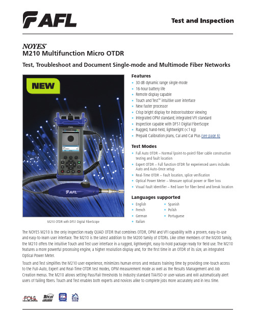
WA2000系列WiFi接入点产品介绍产品概述WA2000是迈普通信技术股份有限公司自主研发的新一代系列室内无线接入设备(简称wifi接入点),支持MIMO,该系列产品共有3款设备,分别支持不同的速率,不同安装方式,全面符合客户各种场景需求。
WA2000-215S-D-PE是单模单频入墙式,工作频段为2.4 GHz,符合IEEE 802.11b/g/n 标准,内置天线,整机150Mbps,适用于KTV包间、酒店房间、中小企业办公室、会议室等区域覆盖部署。
MyPower WA2000-211-D-PE是单模单频吸顶式,工作频段为 2.4 GHz,符合IEEE 802.11b/g/n标准,2*2 MIMO内置天线,整机300Mbps,适用于走廊、酒店房间、中小企业办公室、会议室等区域覆盖部署。
MyPower WA2000-252-D-PE是单模单频壁挂式,工作频段为 2.4 GHz,符合IEEE 802.11b/g/n标准,整机300Mbps,2*2 MIMO外置天线,发射功率可达500mw,适用于走廊、大型房间、会议室等区域覆盖部署。
MyPower WA2000系列室内型wifi接入点具有传输速率高,接收灵敏度高,抗干扰能力强,传输距离远等特点。
设备可独立工作,也可与WNG6000系列融合网关结合实现统一管理,根据客户网络规模量身打造无线接入网络。
独立工作模式适合小型网络环境,随着客户网络环境的不断扩大,可以部署WNG6000系列多业务企业网关,增加wifi接入点设备,实现统一管理。
这种方式不浪费用户的无线接入设备投资,网络规模从小到大平滑升级。
产品特征丰富的胖AP功能,独立架设小型网络设备支持DHCP Server,NAT,PPPoE,黑白名单,策略控制等丰富的胖AP功能,可独立架设一套小型办公网络,组网方便,功能齐全。
支持11N,实现用户数据的300Mbps高速接入遵循IEEE 802.11n设计的高性能无线接入产品,为用户提供高带宽、高质量的WLAN 服务。
Motorola 3.5 kHz 产品说明书
RVN4126 3.59100-386-9100-386/T DEVICERVN41772-CD2-3.5MCS/MTSRVN41821-CD2-3.5XTS3000/SABER PORTABLE YES RKN4046KHVN9085 3.51-20 R NO HLN9359 PROG. STAND RVN4057 3.532 X 8 CODEPLUG NO3080385B23 & 5880385B30 MDVN4965 3.59100-WS/T CONFIG KITRVN4053 3.5ASTRO DIGITAL INTERFACE NO3080385B23RVN41842-CD RKN4046A (Portable) 2-3.5ASTRO PORTABLE /MOBILE YES3080369B73 or0180300B10 (Mobile) RVN41831-CD3080369B732-3.5ASTRO SPECTRA MOBILE YES(Low / Mid Power)0180300B10 (High Power) RVN4185CD ASTRO SPECTRA PLUS MOBILE NO MANY OPTIONS; SEESERVICE BRIEF#SB-MO-0101RVN4186CD ASTRO SPECTRA PLUS MANY OPTIONS;MOBILE/PORTABLE COMB SEE SERVICE BRIEF#SB-MO-0101RVN4154 3.5ASTROTAC 3000 COMPAR.3080385B23RVN5003 3.5ASTROTAC COMPARATORS NO3080399E31 Adpt.5880385B34RVN4083 3.5BSC II NO FKN5836ARVN4171 3.5C200RVN4029 3.5CENTRACOM SERIES II NO VARIOUS-SEE MANUAL6881121E49RVN4112 3.5COMMAND PLUS NORVN4149 3.5COMTEGRA YES3082056X02HVN6053CD CT250, 450, 450LS YES AAPMKN4004RVN4079 3.5DESKTRAC CONVENTIONAL YES3080070N01RVN4093 3.5DESKTRAC TRUNKED YES3080070N01RVN4091 3.5DGT 9000 DESKSET YES0180358A22RVN4114 3.5GLOBAL POSITIONING SYS.NO RKN4021AHVN8177 3.5GM/GR300/GR500/GR400M10/M120/130YES3080070N01RVN4159 3.5GP60 SERIES YES PMLN4074AHVN9128 3.5GP300 & GP350RVN4152 3.5GP350 AVSRVN4150 3.5GTX YES HKN9857 (Portable)3080070N01(Mobile) HVN9025CD HT CDM/MTX/EX SERIES YES AARKN4083/AARKN4081RiblessAARKN4075RIBLESS NON-USA RKN4074RVN4098H 3.5HT1000/JT1000-VISAR YES3080371E46(VISAR CONV)RVN4151 3.5HT1000 AVSRVN4098 3.5HT1000/ VISAR CONV’L.YES RKN4035B (HT1000) HVN9084 3.5i750YES HLN-9102ARVN4156 3.5LCS/LTS 2000YES HKN9857(Portable)3080070N01(Mobile) RVN4087 3.5LORAN C LOC. RECV’R.NO RKN4021ARVN4135 3.5M100/M200,M110,M400,R100 includesHVN9173,9177,9646,9774YES3080070N01RVN4023 3.5MARATRAC YES3080070N01RVN4019 3.5MAXTRAC CONVENTIONAL YES3080070N01RVN4139 3.5MAXTRAC LS YES3080070N01RVN4043 3.5MAXTRAC TRK DUPLEX YES3080070N01RVN4178CD MC SERIES, MC2000/2500DDN6124AW/DB25 CONNECTORDDN6367AW/DB9 CONNECTOR RVN41751-CD Rib to MIC connector 1-3.5MCS2000 RKN4062BRVN41131-3.5MCS2000RVN4011 3.5MCX1000YES3000056M01RVN4063 3.5MCX1000 MARINE YES3000056M01RVN4117 3.5MDC/RDLAP DEVICESRVN4105 3.5MOBILE PROG. TOOLRVN4119 3.5MOBITEX DEVICESRVN4128 3.5MPT1327-1200 SERIES YES SEE MANUALRVN4025 3.5MSF5000/PURC/ANALOG YES0180355A30RVN4077 3.5MSF5000/10000FLD YES0180355A30RVN4017K 3.5MT 1000YES RTK4205CRVN4148 3.5MTR 2000YES3082056X02RVN4140 3.5MTRI 2000NORVN41761-CD MTS2000, MT2000*, MTX8000, MTX90001-3.5*programmed by DOS which is included in the RVN4176RVN4131 3.5MTVA CODE PLUG FIXRVN4142 3.5MTVA DOCTOR YES3080070N01RVN4131 3.5MTVA3.EXERVN4013 3.5MTX800 & MTX800S YES RTK4205CRVN4097 1-CD MTX8000/MTX9000,MTS2000,MT2000*,* programmed by DOS which is included in the RVN4176HVN9067CD MTX850/MTX8250MTX950,MTX925RVN4138 3.5MTX-LS YES RKN4035DRVN4035 3.5MX 1000YES RTK4203CRVN4073 3.5MX 800YES RKN4006BHVN9395 P100, P200 LB, P50+, P210, P500, PR3000RVN4134 3.5P100 (HVN9175)P200 LB (HVN9794)P50+ (HVN9395)P210 (HVN9763)P500 (HVN9941)PR3000 (HVN9586)YES RTK4205HVN9852 3.5P110YES HKN9755A/REX1143 HVN9262 3.5P200 UHF/VHF YES RTK4205RVN4129 3.5PDT220YVN4051 3.5PORTABLE REPEATER Portable rptr.P1820/P1821AXRVN4061C 3.5PP 1000/500NO3080385B23 & 5880385B30 RVN5002 3.5QUANTAR/QUANTRO NO3O80369E31RVN4135 3.5R100 (HVN9177)M100/M200/M110/M400YES0180358A52RVN4146 3.5RPM500/660RVN4002 3.5SABER YES RTK4203CRVN4131 3.5SETTLET.EXEHVN9007 3.5SM50 & SM120YESRVN4039 3.5SMART STATUS YES FKN5825AHVN9054 3.5SOFTWARE R03.2 P1225YES3080070N01HVN9001 3.5SOFTWARE R05.00.00 1225LS YES HLN9359AHVN9012 3.5SP50RVN4001N 3.5SPECTRA YES3080369B73 (STANDARD)0180300B10 (HIGH POWER) RVN4099 3.5SPECTRA RAILROAD YES3080369B73RVN4110 3.5STATION ACCESS MODULE NO3080369E31RVN4089A 3.5STX TRANSIT YES0180357A54RVN4051 3.5SYSTEMS SABER YES RTK4203BRVN4075 3.5T5600/T5620 SERIES NO3080385B23HVN9060CD TC3000, TS3000, TR3000RVN4123 3.5VISAR PRIVACY PLUS YES3080371E46FVN4333 3.5VRM 100 TOOLBOX FKN4486A CABLE &ADAPTORRVN4133 3.5VRM 500/600/650/850NORVN4181CD XTS 2500/5000 PORTABLES RKN4105A/RKN4106A RVN41002- 3.5XTS3000 ASTRO PORTABLE/MOBILERVN4170 3.5XTS3500YES RKN4035DRIB SET UPRLN4008E RADIO INTERFACE BOX (RIB)0180357A57RIB AC POWER PACK 120V0180358A56RIB AC POWER PACK 220V3080369B71IBM TO RIB CABLE (25 PIN) (USE WITH XT & PS2)3080369B72IBM TO RIB CABLE (9 PIN)RLN443825 PIN (F) TO 9 PIN (M) ADAPTOR (USE W/3080369B72 FOR AT APPLICATION) 5880385B308 PIN MODULAR TO 25 PIN ”D” ADAPTOR (FOR T5600 ONLY)0180359A29DUPLEX ADAPTOR (MOSTAR/TRAXAR TRNK’D ONLY)Item Disk Radio RIB Cable Number Size Product Required Number Item Disk Radio RIB Cable Number Size Product Required NumberUtilizing your personal computer, Radio Service Software (RSS)/Customer Programming Software (CPS)/CustomerConfiguration Software (CCS) enables you to add or reprogram features/parameters as your requirements change. RSS/CPS/CCS is compatible with IBM XT, AT, PS/2 models 30, 50, 60 and 80.Requires 640K RAM. DOS 3.1 or later. Consult the RSS users guide for the computer configuration and DOS requirements. (ForHT1000, MT/MTS2000, MTX838/8000/9000, Visar and some newer products —IBM model 386, 4 MEG RAM and DOS 5.0 or higher are recommended.) A Radio Interface Box (RIB) may be required as well as the appropriate cables. The RIB and cables must be ordered separately.Licensing:A license is required before a software (RVN) order is placed. The software license is site specific (customer number and ultimate destination tag). All sites/locations must purchase their own software.Be sure to place subsequent orders using the original customer number and ship-to-tag or other licensed sites; ordering software without a licensed customer number and ultimate tag may result in unnecessary delays. To obtain a no charge license agreement kit, order RPX4719. To place an order in the U.S. call 1-800-422-4210. Outside the U.S., FAX 847-576-3023.Subscription Program:The purchase of Radio ServiceSoftware/Customer Programming/Customer ConfigurationSoftware (RVN & HVN kits) entitles the buyer/subscriber to three years of free upgrades. At the end of these three years, the sub-scriber must purchase the same Radio Service Software kit to receive an additional three years of free upgrades. If the sub-scriber does not elect to purchase the same Radio Service Software kit, no upgrades will be sent. Annually a subscription status report is mailed to inform subscribers of the RSS/CPS/CCS items on our database and their expiration dates.Notes:1)A subscription service is offered on “RVN”-Radio Service Software/Customer Programming/Customer Configuration Software kits only.2)“RVN” software must only be procured through Radio Products and Services Division (RPSD). Software not procured through the RPSD will not be recorded on the subscription database; upgrades will not be mailed.3)Upgrades are mailed to the original buyer (customer number & ultimate tag).4)SP software is available through the radio product groups.The Motorola General Radio Service Software Agreement is now available on Motorola Online. If you need assistance please feel free to submit a “Contact Us” or call 800-422-4210.SMART RIB SET UPRLN1015D SMART RIB0180302E27 AC POWER PACK 120V 2580373E86 AC POWER PACK 220V3080390B49SMARTRIB CABLE (9 PIN (F) TO 9 PIN (M) (USE WITH AT)3080390B48SMARTRIB CABLE (25 PIN (F) TO 9 PIN (M) (USE WITH XT)RLN4488ASMART RIB BATTERY PACKWIRELESS DATA GROUP PRODUTS SOFTWARERVN4126 3.59100-386/9100T DEVICES MDVN4965 3.59100-WS/T CONFIG’TN RVN41173.5MDC/RDLAP DEVICESPAGING PRODUCTS MANUALS6881011B54 3.5ADVISOR6881029B90 3.5ADVISOR ELITE 6881023B20 3.5ADVISOR GOLD 6881020B35 3.5ADVISOR PRO FLX 6881032B30 3.5BR8506881032B30 3.5LS3506881032B30 3.5LS5506881032B30 3.5LS7506881033B10 3.5LS9506881035B20 3.5MINITOR III8262947A15 3.5PAGEWRITER 20008262947A15 3.5PAGEWRITER 2000X 6881028B10 3.5TALKABOUT T3406881029B35 3.5TIMEPORT P7308262947A15 3.5TIMEPORT P930NLN3548BUNIVERSAL INTERFACE KITItem Disk Radio NumberSize Product。
NPort W2150A W2250A 系列无线串行设备服务器说明文档说明书
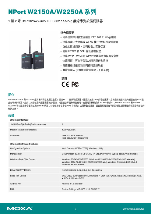
NPort W2150A/W2250A系列1和2埠RS-232/422/485IEEE802.11a/b/g無線串列設備伺服器特色與優點•可將任何串列裝置連接至IEEE802.11a/b/g網路•透過內建乙太網路或WLAN執行Web-based設定•強化的區域網路、串列和電力突波保護•利用HTTPS和SSH強化遠端設定•透過WEP、WPA和WPA2保護存取資料的安全性•快速漫遊,可在存取點之間快速自動切換•具備離線埠緩衝和串列資料記錄功能•雙電源輸入(1螺旋式電源接頭、1端子台)認證簡介NPort®W2150A和W2250A是將串列和乙太網路裝置(例如PLC、儀表和感測器)連接到無線LAN的理想選擇。
您的通訊軟體將能夠透過無線LAN隨處存取串列裝置。
此外,無線裝置伺服器需要較少纜線,相當適合不便佈線的應用。
在基礎架構模式或Ad-Hoc模式中,NPort®W2150A和NPort®W2250A可以連接辦公室和工廠的Wi-Fi網路,以便使用者在多個AP(存取點)之間移動或漫遊,並且對於經常在不同的地點之間移動的裝置提供絕佳的解決方案。
規格Ethernet Interface10/100BaseT(X)Ports(RJ45connector)1Magnetic Isolation Protection 1.5kV(built-in)Standards IEEE802.3for10BaseTIEEE802.3u for100BaseT(X)Ethernet Software FeaturesConfiguration Options Web Console(HTTP/HTTPS),Windows UtilityManagement DHCP Option82,HTTP,IPv4,SMTP,SNMPv1/v2c/v3,Syslog,Telnet,Web Console Windows Real COM Drivers Windows95/98/ME/NT/2000,Windows XP/2003/Vista/2008/7/8/8.1/10(x86/x64),Windows2008R2/2012/2012R2/2016/2019(x64),Windows Embedded CE5.0/6.0,Windows XP EmbeddedLinux Real TTY Drivers Kernel versions:2.4.x,2.6.x,3.x,4.x,and5.xFixed TTY Drivers SCO UNIX,SCO OpenServer,UnixWare7,QNX4.25,QNX6,Solaris10,FreeBSD,AIX5.x,HP-UX11i,Mac OS XAndroid API Android3.1.x and laterMIB Device Settings MIB,RFC1213,RFC1317Security HTTPS/SSL,User Authentication Management:local database,RADIUS,SecureProtocols:HTTPS(TLSv1.2),SSH,SNMPv3,Cryptography:HMAC,SHA-1,SHA-256,SHA-384,RSA-1024,AES-128,AES-256Time Management NTP Client,SNTP ClientWLAN InterfaceWLAN Standards802.11a/b/g/nReceiver Sensitivity for802.11a(measured at5.680 GHz)Typ.-91@6Mbps Typ.-74@54MbpsReceiver Sensitivity for802.11b(measured at2.437 GHz)Typ.-92dBm@1Mbps Typ.-84dBm@11MbpsReceiver Sensitivity for802.11g(measured at2.437 GHz)Typ.-91dBm@6Mbps Typ.-73dBm@54MbpsReceiver Sensitivity for802.11n(2.4GHz;measured at2.437GHz)Typ.-89dBm@6.5Mbps(20MHz) Typ.-71dBm@72.2Mbps(20MHz)Receiver Sensitivity for802.11n(5GHz;measured at 5.680GHz)Typ.-89dBm@6.5Mbps(20MHz) Typ.-71dBm@72.2Mbps(20MHz) Typ.-85dBm@13.5Mbps(40MHz) Typ.-67dBm@150Mbps(40MHz)Modulation Type DSSSOFDMTransmission Distance Up to100meters(in open areas) Transmission Rate802.11a/g:54Mbps802.11b:11Mbps802.11n:6.5to150Mbps Transmitter Power for802.11b16±1.5dBm@1Mbps16±1.5dBm@11Mbps Transmitter Power for802.11g16±1.5dBm@6Mbps14±1.5dBm@54Mbps Transmitter Power for802.11a15±1.5dBm@6Mbps14±1.5dBm@54Mbps Transmitter Power for802.11n(2.4GHz)16dBm@1.5Mbps(6.5MHz)12dBm@1.5Mbps(72.2MHz) Transmitter Power for802.11n(5GHz)15dBm@1.5Mbps(6.5MHz)12dBm@1.5Mbps(150MHz) Frequency Band for CN(20MHz operating channels) 2.412to2.472GHz(13channels)5.180to5.240GHz(4channels)5.260to5.320GHz(4channels)15.745to5.825GHz(5channels) Frequency Band for EU(20MHz operating channels) 2.412to2.472GHz(13channels)5.180to5.240GHz(4channels)5.260to5.320GHz(4channels)15.500to5.700GHz(11channels)1 Frequency Band for JP(20MHz operating channels) 2.412to2.484GHz(14channels)5.180to5.240GHz(4channels)5.260to5.320GHz(4channels)15.500to5.700GHz(11channels)1 Frequency Band for US(20MHz operating channels) 2.412to2.462GHz(11channels)5.180to5.240GHz(4channels)5.260to5.320GHz(4channels)25.500to5.700GHz(11channels)25.745to5.825GHz(5channels)Wireless Security WEP encryption(64-bit and128-bit)WPA/WPA2-Enterprise(IEEE802.1X/RADIUS,TKIP,AES)WPA/WPA2-PersonalWLAN Modes Ad-hoc Mode,Infrastructure modeSerial InterfaceConnector DB9maleNo.of Ports NPort W2150A/W2150A-T:1NPort W2250A/W2250A-T:2Serial Standards RS-232,RS-422,RS-485Operation Modes Real COM mode,TCP Server mode,TCP Client mode,UDP mode,RFC2217mode,PairConnection mode,Ethernet Modem mode,DisabledBaudrate50bps to921.6kbpsData Bits5,6,7,8Stop Bits1,1.5,2Parity None,Even,Odd,Space,MarkFlow Control None,RTS/CTS,XON/XOFFRS-485Data Direction Control ADDC®(automatic data direction control)Pull High/Low Resistor for RS-4851kilo-ohm,150kilo-ohmsTerminator for RS-485120ohmsSurge1kVPhysical CharacteristicsHousing MetalInstallation Desktop,DIN-rail mounting(with optional kit),Wall mountingDimensions(with ears,without antenna)77x111x26mm(3.03x4.37x1.02in)Dimensions(without ears or antenna)100x111x26mm(3.94x4.37x1.02in)Weight NPort W2150A/W2150A-T:547g(1.21lb)NPort W2250A/W2250A-T:557g(1.23lb)Antenna Length109.79mm(4.32in)Environmental LimitsOperating Temperature Standard Models:0to55°C(32to131°F)Wide Temp.Models:-40to75°C(-40to167°F)Storage Temperature(package included)-40to75°C(-40to167°F)Ambient Relative Humidity5to95%(non-condensing)Power ParametersInput Current NPort W2150A/W2150A-T:179mA@12VDCNPort W2250A/W2250A-T:200mA@12VDCInput Voltage12to48VDCStandards and CertificationsEMC EN55032/24EMI CISPR32,FCC Part15B Class AEMS IEC61000-4-2ESD:Contact:4kV;Air:8kVIEC61000-4-3RS:80MHz to1GHz:3V/mIEC61000-4-4EFT:Power:2kV;Signal:2kVIEC61000-4-5Surge:Power:2kV;Signal:1kVIEC61000-4-6CS:150kHz to80MHz:3V/m;Signal:3V/mIEC61000-4-8PFMFIEC61000-4-11Radio Frequency CE(ETSI EN301893,ETSI EN300328,ETSI EN301489-17,ETSI EN301489-1),ARIBRCR STD-33,ARIB STD-66ReliabilityAlert Tools RTC(real-time clock)Automatic Reboot Trigger Built-in WDTMTBFTime NPort W2150A/W2150A-T:383,187hrsNPort W2250A/W2250A-T:363,327hrsStandards Telcordia(Bellcore)Standard TR/SRWarrantyWarranty Period5yearsDetails See /tw/warrantyPackage ContentsDevice1x NPort W2150A/W2250A Series device serverPower Supply1x power adapter,suitable for your region(standard temp.models only)Antenna1x2.4/5GHz antennaDocumentation1x quick installation guide1x warranty card尺寸訂購資訊Model Name No.of serial portsWLAN Channels Input Current Operating Temp.Power Adapter inBox Notes NPort W2150A-CN 1China bands 179mA @12VDC 0to 55°C Yes (CN plug)—NPort W2150A-EU 1Europe bands 179mA @12VDC 0to 55°C Yes (EU/UK/AUplug)—NPort W2150A-EU/KC 1Europe bands 179mA @12VDC 0to 55°C Yes (EU plug)KC certificateNPort W2150A-JP 1Japan bands 179mA @12VDC 0to 55°C Yes (JP plug)—NPort W2150A-US 1US bands 179mA @12VDC 0to 55°C Yes (US plug)—NPort W2150A-T-CN 1China bands 179mA @12VDC -40to 75°C No —NPort W2150A-T-EU 1Europe bands 179mA @12VDC -40to 75°C No —NPort W2150A-T-JP 1Japan bands 179mA @12VDC -40to 75°C No —NPort W2150A-T-US 1US bands 179mA @12VDC -40to 75°C No —NPort W2250A-CN 2China bands 200mA @12VDC 0to 55°C Yes (CN plug)—NPort W2250A-EU 2Europe bands 200mA @12VDC 0to 55°C Yes (EU/UK/AUplug)—NPort W2250A-EU/KC 2Europe bands 200mA @12VDC 0to 55°C Yes (EU plug)KC certificateNPort W2250A-JP 2Japan bands 200mA @12VDC 0to 55°C Yes (JP plug)—NPort W2250A-US 2US bands 200mA @12VDC 0to 55°C Yes (US plug)—NPort W2250A-T-CN 2China bands 200mA @12VDC -40to 75°C No —NPort W2250A-T-EU 2Europe bands 200mA @12VDC -40to 75°C No —NPort W2250A-T-JP 2Japan bands 200mA @12VDC -40to 75°C No —NPort W2250A-T-US2US bands200mA @12VDC-40to 75°CNo—配件(選購)AntennasANT-WDB-ARM-02 2.4/5GHz,omni-directional rubber duck antenna,2dBi,RP-SMA(male)CablesCBL-F9M9-150DB9female to DB9male serial cable,1.5mCBL-F9M9-20DB9female to DB9male serial cable,20cmConnectorsADP-RJ458P-DB9F DB9female to RJ45connectorMini DB9F-to-TB DB9female to terminal block connectorDIN-Rail Mounting KitsDK35A DIN-rail mounting kit,35mmPower AdaptersPWR-12050-WPAU-S1Locking barrel plug,12VDC,0.5A,100-240VAC,Australia(AU)plug,0to40°C operating temperature PWR-12050-WPCN-S1Locking barrel plug,12VDC,0.5A,100to240VAC,China(CN)plug,0to40°C operating temperature PWR-12050-WPEU-S1Locking barrel plug,12VDC,0.5A,100-240VAC,Continental Europe(EU)plug,0to40°C operatingtemperaturePWR-12050-WPUK-S1Locking barrel plug,12VDC,0.5A,100-240VAC,United Kingdom(UK)plug,0to40°C operatingtemperaturePWR-12050-WPUSJP-S1Locking barrel plug,12VDC,0.5A,100-240VAC,United States/Japan(US/JP)plug,0to40°C operatingtemperaturePWR-12150-AU-SA-T Locking barrel plug,12VDC,1.5A,100-240VAC,Australia(AU)plug,-40to75°C operating temperatureApplicable Models:NPort W2150A-TNPort W2250A-TPWR-12150-CN-SA-T Wide-temperature(-40to75°C)locking barrel plug,12VDC,1.5A,100to240VAC,China(CN)plugApplicable Models:NPort W2150A-TNPort W2250A-TPWR-12150-EU-SA-T Locking barrel plug,12VDC,1.5A,100-240VAC,Continental Europe(EU)plug,-40to75°C operatingtemperatureApplicable Models:NPort W2150A-TNPort W2250A-TPWR-12150-UK-SA-T Locking barrel plug,12VDC,1.5A,100-240VAC,United Kingdom(UK)plug,-40to75°C operatingtemperatureApplicable Models:NPort W2150A-TNPort W2250A-TPWR-12150-USJP-SA-T Locking barrel plug,12VDC1.5A,100-240VAC,United States/Japan(US/JP)plug,-40to75°Coperating temperatureApplicable Models:NPort W2150A-TNPort W2250A-TPower CordsCBL-PJ21NOPEN-BK-30Locking barrel plug to bare-wire cable©Moxa Inc.版權所有.2021年1月25日更新。
H3C无线控制器

TDJ-SA2400-11-90
TQJ-2400BKF-Y
SL13090A
TQC-2400CI
TDJ-2400IA(-45)
SL14011A
SL14166A
H3C 无线局域网 5.8GHz 天线组件
-全向&定向天线-802.11a
率接入点-FIT
H3C WA2220X-AGE-无线局域网室外增强型 AG 双频双模接入点FIT
对全部高中资料试卷电气设备,在安装过程中以及安装结束后进行高中资料试卷调整试验;通电检查所有设备高中资料电试力卷保相护互装作置用调与试相技互术关,系电,力通根保1据过护生管高产线中工敷资艺设料高技试中术卷资0配不料置仅试技可卷术以要是解求指决,机吊对组顶电在层气进配设行置备继不进电规行保范空护高载高中与中资带资料负料试荷试卷下卷问高总题中体2资2配,料置而试时且卷,可调需保控要障试在各验最类;大管对限路设度习备内题进来到行确位调保。整机在使组管其高路在中敷正资设常料过工试程况卷中下安,与全要过,加度并强工且看作尽护下可1都关能可于地以管缩正路小常高故工中障作资高;料中对试资于卷料继连试电接卷保管破护口坏进处范行理围整高,核中或对资者定料对值试某,卷些审弯异核扁常与度高校固中对定资图盒料纸位试,置卷编.工保写况护复进层杂行防设自腐备动跨与处接装理地置,线高尤弯中其曲资要半料避径试免标卷错高调误等试高,方中要案资求,料技编试术写5、卷交重电保底要气护。设设装管备备置线4高、调动敷中电试作设资气高,技料课中并术3试、件资且中卷管中料拒包试路调试绝含验敷试卷动线方设技作槽案技术,、以术来管及避架系免等统不多启必项动要方方高式案中,;资为对料解整试决套卷高启突中动然语过停文程机电中。气高因课中此件资,中料电管试力壁卷高薄电中、气资接设料口备试不进卷严行保等调护问试装题工置,作调合并试理且技利进术用行,管过要线关求敷运电设行力技高保术中护。资装线料置缆试做敷卷到设技准原术确则指灵:导活在。。分对对线于于盒调差处试动,过保当程护不中装同高置电中高压资中回料资路试料交卷试叉技卷时术调,问试应题技采,术用作是金为指属调发隔试电板人机进员一行,变隔需压开要器处在组理事在;前发同掌生一握内线图部槽纸故内资障,料时强、,电设需回备要路制进须造行同厂外时家部切出电断具源习高高题中中电资资源料料,试试线卷卷缆试切敷验除设报从完告而毕与采,相用要关高进技中行术资检资料查料试和,卷检并主测且要处了保理解护。现装场置设。备高中资料试卷布置情况与有关高中资料试卷电气系统接线等情况,然后根据规范与规程规定,制定设备调试高中资料试卷方案。
腾达无线路由器拆机图

/thread-189839-1-1.html 如果你的路由,软件版本是 V5.07.XX 则推荐升级至 W3000R 的 V5.07.40 该固件修复了 DNS 主次颠倒的 BUG,支持 13 频段,新增 ClientAP 模式 /tendacn/DownLoads/show.aspx?downid=807 N300 拆机图
供電
刚买的,到手拆了。* e' d7 ?% I r
; q" M9 q% E8 A7 G) o2 {* t
产品型号:腾达 W3000R 增强型无线覆盖王路由器 (包装上这么写的,国产的很多称 xx 王的) 出厂日期: 2013 年 4 月 }# x+ d. Z) t8 E( a 主芯片: BCM5357C0KFBG 功放芯片: 2 片, SiGE 2605L , 功放最大输出功率 26 dBm (400mW) Flash: 2MB RAM: 16MB, EM6A9160TSA-5G8 b7 W5 R2 Z/ b9 v5 g+ Q- L
騰達 N301 v2 300M 路由器 拆機/拆解
2013-10-27 21:19:41| 分类: 科技評測|举报|字号 订阅
該路由器的反面
打開後呈現的主板圖片
網絡 CPU 博通 BCM5357 (500Mhz)
處理器反面的電路 網路缓存(快取)芯片,鈺創 EM6A9160TSA-5G
Tenda 的 300M 无线路由,主要有 N300,837R,W308R,W309R,W3000R 五款机器使用的芯片均为 BCM5357,都可原生支持 WISP flash 容量都是 2M 其中 N300 使用 RAM 大小为 32M(EM6AA160TSB 和 W9425G6JH 都是 32M) ,其余四款 RAM 都是 16M W309R 和 W3000R 的天线为可拆卸式 N300,837R,W308R 天线为固定式 5dbi(其中 837R 早期版本天线为 3dbi) 腾达这五个机型 WISP 都不会出现掉速的情况 实测使用 WISP 连接网速达 440K/S 的 AP(信号强度为-68) 有线速度为 430K/S,无线速度为 420K/S 如果是持续高强度使用(比如迅雷下载),可保持高速稳定 但是,由于 BCM 的省电机制没有考虑 WISP,如果一段时间不访问网络就可能会断开连接.可以通过手动修改配 置文件来解决此问题.
ATEN Altusen CN9950 单端口KVM over IP交换机说明书

1-Local / Remote Share Access Single PortKVM over IP SwitchCN9000 / CN9600 / CN9950User ManualCN9000 / CN9600 / CN9950CN9000 / CN9600 / CN9950 User Manual iiEMC InformationFEDERAL COMMUNICATIONS COMMISSION INTERFERENCE STATEMENTThis equipment has been tested and found to comply with the limits for a Class A digital device, pursuant to Part 15 of the FCC Rules. These limits are designed to provide reasonable protection against harmful interference when the equipment is operated in a commercial environment. This equipment generates, uses, and can radiate radio frequency energy and, if not installed and used in accordance with the instruction manual, may cause harmful interference to radio communications. Operation of this equipment in a residential area is likely to cause harmful interference in which case the user will be required to correct the interference at his own expense.This device complies with Part 15 of the FCC Rules. Operation is subject to the following two conditions: (1) this device may not cause harmful interference, and (2) this device must accept any interference received, including interference that may cause undesired operation.FCC CautionAny changes or modifications not expressly approved by the party responsible for compliance could void the user's authority to operate this equipment.WarningOperation of this equipment in a residential environment could cause radio interference.AchtungDer Gebrauch dieses Geräts in Wohnumgebung kann Funkstörungen verursachen.KCC Statement :CN9000 / CN9600 / CN9950 User Manual iiiIndustry Canada StatementThis Class A digital apparatus complies with Canadian ICES-003.RoHS This product is RoHS compliant.About This ManualThis manual is provided to help you get the most out of your CN9000 / CN9600 / CN9950. It covers all aspects of the device, including installation, configuration, and operation.The models covered in this manual include:An overview of the information found in the manual is provided below.Chapter 1, Introduction , introduces you to the CN9000 / CN9600 / CN9950 KVM over IP Switch, its purpose, features and benefits, with its front and back panel components described.Chapter 2, Hardware Setup , provides step-by-step instructions for setting up the device, and explains its basic operation procedures.Chapter 3, Browser Login , describes how to log into the CN9000 / CN9600 / CN9950 with a browser, and the various functions included.Chapter 4, Configuration , explains the CN9000 / CN9600 / CN9950’s system settings that can be configured to suit its working environment.Chapter 5, Accessing Remote Server , describes how to access the CN9000 / CN9600 / CN9950 remotely.Model Product Name CN90001-Local / Remote Share Access Single Port VGA KVM over IP Switch CN96001-Local / Remote Share Access Single Port DVI KVM over IP Switch CN99501-Local / Remote Share Access Single Port 4K DisplayPort KVM over IP SwitchCN9000 / CN9600 / CN9950 User Manual ivChapter 6, The Windows Client Viewer , explains how to remotely access the server connected to the CN9000 / CN9600 / CN9950’s port using a WinClient, Java Client, and Web Client viewerChapter 7, Local Access , describes how to access the CN9000 / CN9600 / CN9950 locally.Chapter 8, The Log File , shows how to use the log file utility to view the events that take place on the CN9000 / CN9600 / CN9950.Chapter 9, The Log Server , explains how to install and configure the Log Server.Appendix , provides specifications and other technical information regarding the CN9000 / CN9600 / CN9950.Conventions This manual uses the following conventions:MonospacedIndicates text that you should key in.[ ]Indicates keys you should press. For example, [Enter] means topress the Enter key. If keys need to be chorded, they appeartogether in the same bracket with a plus sign between them:[Ctrl+Alt].1.Numbered lists represent procedures with sequential steps.♦Bullet lists provide information, but do not involve sequential steps.>Indicates consecutive selections, such as options on a menu ordialog box. For example, Start > Run means to open the Startmenu, and then select Run .Indicates critical information.CN9000 / CN9600 / CN9950 User Manual Package ContentsCN9000♦1CN9000 KVM over IP Switch♦1KVM cable (SPHD to VGA, PS/2, USB)♦1USB Type-A to USB Mini-B cable♦1power adapter♦1mounting kit♦1control terminal block♦1foot pad set (4 pcs)♦1user instructions*CN9600♦1CN9600 KVM over IP Switch♦1KVM cable (DVI-D, USB Type-A, audio)♦1USB Type-A to USB Mini-B cable♦1power adapter♦1mounting kit♦1user instructions*CN9950♦1CN9950 KVM over IP Switch♦1DisplayPort cable♦1USB Type-A to USB Type-B cable♦1USB Type-A to USB Mini-B cable♦1power adapter♦1mounting kit♦1control terminal block♦1foot pad set (4 pcs)♦1user instructions*vCN9000 / CN9600 / CN9950 User Manual vi*Features may have been added to the CN9000 / CN9600 / CN9950 since this manual was released. Please visit our website to download the most up-to-date version.Check to make sure that all components are present and in working condition. If you encounter any problems, please contact your local dealer.Read this manual thoroughly and follow the installation and operation procedures to prevent any damage to the unit and/or any devices connected to it.Product InformationFor information about all ATEN products and how they can help you connect without limits, visit ATEN on the Web or contact an ATEN Authorized Reseller. Visit ATEN on the Web for a list of locations and telephone numbers:International North America CN9000 / CN9600 / CN9950 User Manual viiUser Information Online RegistrationBe sure to register your product at our online support center:Telephone SupportFor telephone support, call this number:User NoticeAll information, documentation, and specifications contained in this manual are subject to change without prior notification by the manufacturer. The manufacturer makes no representations or warranties, either expressed or implied, with respect to the contents hereof and specifically disclaims any warranties as to merchantability or fitness for any particular purpose. Any of the manufacturer's software described in this manual is sold or licensed as is . Should the programs prove defective following their purchase, the buyer (and not the manufacturer, its distributor, or its dealer), assumes the entire cost of all necessary servicing, repair and any incidental or consequential damages resulting from any defect in the software.The manufacturer of this system is not responsible for any radio and/or TV interference caused by unauthorized modifications to this device. It is the responsibility of the user to correct such interference.The manufacturer is not responsible for any damage incurred in the operation of this system if the correct operational voltage setting was not selected prior to operation. PLEASE VERIFY THAT THE VOLTAGE SETTING IS CORRECT BEFORE USE.International International886-2-8692-6959China86-400-810-0-810Japan81-3-5615-5811Korea82-2-467-6789North America 1-888-999-ATEN ext 49881-949-428-1111CN9000 / CN9600 / CN9950 User ManualContentsEMC Information. . . . . . . . . . . . . . . . . . . . . . . . . . . . . . . . . . . . . . . . . . . . . ii About this Manual. . . . . . . . . . . . . . . . . . . . . . . . . . . . . . . . . . . . . . . . . . . .iii Conventions . . . . . . . . . . . . . . . . . . . . . . . . . . . . . . . . . . . . . . . . . . . . .iv Package Contents . . . . . . . . . . . . . . . . . . . . . . . . . . . . . . . . . . . . . . . . . . . v Product Information . . . . . . . . . . . . . . . . . . . . . . . . . . . . . . . . . . . . . . . . . .vi User Information. . . . . . . . . . . . . . . . . . . . . . . . . . . . . . . . . . . . . . . . . . . . vii Online Registration . . . . . . . . . . . . . . . . . . . . . . . . . . . . . . . . . . . . . . . vii Telephone Support . . . . . . . . . . . . . . . . . . . . . . . . . . . . . . . . . . . . . . . vii User Notice. . . . . . . . . . . . . . . . . . . . . . . . . . . . . . . . . . . . . . . . . . . . . vii 1.IntroductionOverview. . . . . . . . . . . . . . . . . . . . . . . . . . . . . . . . . . . . . . . . . . . . . . . . . . .1 Features and Benefits. . . . . . . . . . . . . . . . . . . . . . . . . . . . . . . . . . . . . . . . .2 Hardware. . . . . . . . . . . . . . . . . . . . . . . . . . . . . . . . . . . . . . . . . . . . . . . .2 Management. . . . . . . . . . . . . . . . . . . . . . . . . . . . . . . . . . . . . . . . . . . . .3 Easy-to-Use Interface. . . . . . . . . . . . . . . . . . . . . . . . . . . . . . . . . . . . . .4 Advanced Security . . . . . . . . . . . . . . . . . . . . . . . . . . . . . . . . . . . . . . . .4 Virtual Media. . . . . . . . . . . . . . . . . . . . . . . . . . . . . . . . . . . . . . . . . . . . .4 Virtual Remote Desktop . . . . . . . . . . . . . . . . . . . . . . . . . . . . . . . . . . . .5 System Requirements . . . . . . . . . . . . . . . . . . . . . . . . . . . . . . . . . . . . . . . .6 Remote User Computers . . . . . . . . . . . . . . . . . . . . . . . . . . . . . . . . . . .6 Servers . . . . . . . . . . . . . . . . . . . . . . . . . . . . . . . . . . . . . . . . . . . . . . . . .6 Cables. . . . . . . . . . . . . . . . . . . . . . . . . . . . . . . . . . . . . . . . . . . . . . . . . .7 Supported Video Resolutions . . . . . . . . . . . . . . . . . . . . . . . . . . . . . . . .8 Operating Systems . . . . . . . . . . . . . . . . . . . . . . . . . . . . . . . . . . . . . . . .8 Browsers. . . . . . . . . . . . . . . . . . . . . . . . . . . . . . . . . . . . . . . . . . . . . . . .9 Components. . . . . . . . . . . . . . . . . . . . . . . . . . . . . . . . . . . . . . . . . . . . . . .10 CN9000 Front View. . . . . . . . . . . . . . . . . . . . . . . . . . . . . . . . . . . . . . .10 CN9000 Rear View. . . . . . . . . . . . . . . . . . . . . . . . . . . . . . . . . . . . . . .11 CN9000/CN9950 Side View . . . . . . . . . . . . . . . . . . . . . . . . . . . . . . . .12 CN9950 Front View. . . . . . . . . . . . . . . . . . . . . . . . . . . . . . . . . . . . . . .13 9950 Rear View. . . . . . . . . . . . . . . . . . . . . . . . . . . . . . . . . . . . . . . . . .14 CN9600 Front View. . . . . . . . . . . . . . . . . . . . . . . . . . . . . . . . . . . . . . .15 CN9600 Rear View. . . . . . . . . . . . . . . . . . . . . . . . . . . . . . . . . . . . . . .16 2.Hardware SetupMounting. . . . . . . . . . . . . . . . . . . . . . . . . . . . . . . . . . . . . . . . . . . . . . . . . .17 Attaching the Bracket . . . . . . . . . . . . . . . . . . . . . . . . . . . . . . . . . .17Rack Mount. . . . . . . . . . . . . . . . . . . . . . . . . . . . . . . . . . . . . . . . . .18Wall Mount . . . . . . . . . . . . . . . . . . . . . . . . . . . . . . . . . . . . . . . . . .19 Hardware Installation . . . . . . . . . . . . . . . . . . . . . . . . . . . . . . . . . . . . . . . .20 CN9000. . . . . . . . . . . . . . . . . . . . . . . . . . . . . . . . . . . . . . . . . . . . . . . .21 CN9600. . . . . . . . . . . . . . . . . . . . . . . . . . . . . . . . . . . . . . . . . . . . . . . .22 viiiCN9000 / CN9600 / CN9950 User Manual CN9950. . . . . . . . . . . . . . . . . . . . . . . . . . . . . . . . . . . . . . . . . . . . . . . . . . .23 DCE and DTE Ports . . . . . . . . . . . . . . . . . . . . . . . . . . . . . . . . . . . . . . . . .24 3.Browser LoginLogging In. . . . . . . . . . . . . . . . . . . . . . . . . . . . . . . . . . . . . . . . . . . . . . . . .25 Main Screen . . . . . . . . . . . . . . . . . . . . . . . . . . . . . . . . . . . . . . . . . . . . . . .27 4.ConfigurationIntroduction. . . . . . . . . . . . . . . . . . . . . . . . . . . . . . . . . . . . . . . . . . . . . . . .29 Basic Setting. . . . . . . . . . . . . . . . . . . . . . . . . . . . . . . . . . . . . . . . . . . . . . .30 User Management. . . . . . . . . . . . . . . . . . . . . . . . . . . . . . . . . . . . . . . .30 User Information . . . . . . . . . . . . . . . . . . . . . . . . . . . . . . . . . . . . . .30Role. . . . . . . . . . . . . . . . . . . . . . . . . . . . . . . . . . . . . . . . . . . . . . . .30Permissions. . . . . . . . . . . . . . . . . . . . . . . . . . . . . . . . . . . . . . . . . .31 Account Policy. . . . . . . . . . . . . . . . . . . . . . . . . . . . . . . . . . . . . . . . . . .32 Sessions . . . . . . . . . . . . . . . . . . . . . . . . . . . . . . . . . . . . . . . . . . . . . . .33 Maintenance . . . . . . . . . . . . . . . . . . . . . . . . . . . . . . . . . . . . . . . . . . . .34 Upgrade Main Firmware . . . . . . . . . . . . . . . . . . . . . . . . . . . . . . . .34Update Display Information. . . . . . . . . . . . . . . . . . . . . . . . . . . . . .35Backup / Restore. . . . . . . . . . . . . . . . . . . . . . . . . . . . . . . . . . . . . .36Terminal. . . . . . . . . . . . . . . . . . . . . . . . . . . . . . . . . . . . . . . . . . . . .38 Advanced Setting . . . . . . . . . . . . . . . . . . . . . . . . . . . . . . . . . . . . . . . . . . .39 Device Information . . . . . . . . . . . . . . . . . . . . . . . . . . . . . . . . . . . . . . .39 General . . . . . . . . . . . . . . . . . . . . . . . . . . . . . . . . . . . . . . . . . . . . .39 Network. . . . . . . . . . . . . . . . . . . . . . . . . . . . . . . . . . . . . . . . . . . . . . . .41 IP Installer . . . . . . . . . . . . . . . . . . . . . . . . . . . . . . . . . . . . . . . . . . .42Service Ports. . . . . . . . . . . . . . . . . . . . . . . . . . . . . . . . . . . . . . . . .42Redundant NIC . . . . . . . . . . . . . . . . . . . . . . . . . . . . . . . . . . . . . . .43IPv4 Settings . . . . . . . . . . . . . . . . . . . . . . . . . . . . . . . . . . . . . . . . .43IPv6 Settings . . . . . . . . . . . . . . . . . . . . . . . . . . . . . . . . . . . . . . . . .44Network Transfer Rate. . . . . . . . . . . . . . . . . . . . . . . . . . . . . . . . . .44DDNS. . . . . . . . . . . . . . . . . . . . . . . . . . . . . . . . . . . . . . . . . . . . . . .44 ANMS . . . . . . . . . . . . . . . . . . . . . . . . . . . . . . . . . . . . . . . . . . . . . . . . .45 Event Destination. . . . . . . . . . . . . . . . . . . . . . . . . . . . . . . . . . . . . .45SMTP Settings. . . . . . . . . . . . . . . . . . . . . . . . . . . . . . . . . . . . . . . .46Authentication . . . . . . . . . . . . . . . . . . . . . . . . . . . . . . . . . . . . . . . .48 Security. . . . . . . . . . . . . . . . . . . . . . . . . . . . . . . . . . . . . . . . . . . . . . . .51 Login Failures . . . . . . . . . . . . . . . . . . . . . . . . . . . . . . . . . . . . . . . .51Filter. . . . . . . . . . . . . . . . . . . . . . . . . . . . . . . . . . . . . . . . . . . . . . . .52Encryption . . . . . . . . . . . . . . . . . . . . . . . . . . . . . . . . . . . . . . . . . . .54Security Level . . . . . . . . . . . . . . . . . . . . . . . . . . . . . . . . . . . . . . . .54Mode . . . . . . . . . . . . . . . . . . . . . . . . . . . . . . . . . . . . . . . . . . . . . . .55Private Certificate . . . . . . . . . . . . . . . . . . . . . . . . . . . . . . . . . . . . .55Certificate Signing Request. . . . . . . . . . . . . . . . . . . . . . . . . . . . . .57 Console Management. . . . . . . . . . . . . . . . . . . . . . . . . . . . . . . . . . . . .59 OOBC . . . . . . . . . . . . . . . . . . . . . . . . . . . . . . . . . . . . . . . . . . . . . .59ixCN9000 / CN9600 / CN9950 User ManualxDial Out. . . . . . . . . . . . . . . . . . . . . . . . . . . . . . . . . . . . . . . . . . . . .61 Serial Console. . . . . . . . . . . . . . . . . . . . . . . . . . . . . . . . . . . . . . . .63 Date/Time . . . . . . . . . . . . . . . . . . . . . . . . . . . . . . . . . . . . . . . . . . . . . .66 Time Zone. . . . . . . . . . . . . . . . . . . . . . . . . . . . . . . . . . . . . . . . . . .66 Date / Time . . . . . . . . . . . . . . . . . . . . . . . . . . . . . . . . . . . . . . . . . .66 Network Time . . . . . . . . . . . . . . . . . . . . . . . . . . . . . . . . . . . . . . . .67 Customization. . . . . . . . . . . . . . . . . . . . . . . . . . . . . . . . . . . . . . . . . . .67 Mode. . . . . . . . . . . . . . . . . . . . . . . . . . . . . . . . . . . . . . . . . . . . . . .68 USB IO Settings . . . . . . . . . . . . . . . . . . . . . . . . . . . . . . . . . . . . . .68 Multiuser Mode . . . . . . . . . . . . . . . . . . . . . . . . . . . . . . . . . . . . . . .68 Exit Macro. . . . . . . . . . . . . . . . . . . . . . . . . . . . . . . . . . . . . . . . . . .69 Reset. . . . . . . . . . . . . . . . . . . . . . . . . . . . . . . . . . . . . . . . . . . . . . .69 Preferences . . . . . . . . . . . . . . . . . . . . . . . . . . . . . . . . . . . . . . . . . . . . . . .70 User Preferences . . . . . . . . . . . . . . . . . . . . . . . . . . . . . . . . . . . . . . . .70 Logs . . . . . . . . . . . . . . . . . . . . . . . . . . . . . . . . . . . . . . . . . . . . . . . . . .71 Remote Console. . . . . . . . . . . . . . . . . . . . . . . . . . . . . . . . . . . . . . . . .72 Remote Console Preview . . . . . . . . . . . . . . . . . . . . . . . . . . . . . . .72 Telnet Viewer . . . . . . . . . . . . . . . . . . . . . . . . . . . . . . . . . . . . . . . .72 Download . . . . . . . . . . . . . . . . . . . . . . . . . . . . . . . . . . . . . . . . . . . . . .73 About . . . . . . . . . . . . . . . . . . . . . . . . . . . . . . . . . . . . . . . . . . . . . . . . . . . .73 Viewer. . . . . . . . . . . . . . . . . . . . . . . . . . . . . . . . . . . . . . . . . . . . . . . . . . . .73 Logout. . . . . . . . . . . . . . . . . . . . . . . . . . . . . . . . . . . . . . . . . . . . . . . . . . . .745.Accessing Remote ServerIntroduction. . . . . . . . . . . . . . . . . . . . . . . . . . . . . . . . . . . . . . . . . . . . . . . .75 Web, Windows and Java Client Viewer . . . . . . . . . . . . . . . . . . . . . . . . . .76 The Windows Client AP . . . . . . . . . . . . . . . . . . . . . . . . . . . . . . . . . . . . . .77 Download . . . . . . . . . . . . . . . . . . . . . . . . . . . . . . . . . . . . . . . . . . . . . .77 Starting Up . . . . . . . . . . . . . . . . . . . . . . . . . . . . . . . . . . . . . . . . . . . . .77 The Java Client AP. . . . . . . . . . . . . . . . . . . . . . . . . . . . . . . . . . . . . . . . . .80 6.The Windows Client ViewerThe Win / Java Client Control Panel. . . . . . . . . . . . . . . . . . . . . . . . . . . . .81 Control Panel Functions . . . . . . . . . . . . . . . . . . . . . . . . . . . . . . . . . . .82 Macros . . . . . . . . . . . . . . . . . . . . . . . . . . . . . . . . . . . . . . . . . . . . . . . .85 Hotkeys. . . . . . . . . . . . . . . . . . . . . . . . . . . . . . . . . . . . . . . . . . . . .85User Macros . . . . . . . . . . . . . . . . . . . . . . . . . . . . . . . . . . . . . . . . .87System Macros . . . . . . . . . . . . . . . . . . . . . . . . . . . . . . . . . . . . . . .91 Video Settings. . . . . . . . . . . . . . . . . . . . . . . . . . . . . . . . . . . . . . . . . . .93 Gamma Adjustment. . . . . . . . . . . . . . . . . . . . . . . . . . . . . . . . . . . .94 The Message Board . . . . . . . . . . . . . . . . . . . . . . . . . . . . . . . . . . . . . .96 The Button Bar . . . . . . . . . . . . . . . . . . . . . . . . . . . . . . . . . . . . . . .96Message Display Panel. . . . . . . . . . . . . . . . . . . . . . . . . . . . . . . . .97Compose Panel. . . . . . . . . . . . . . . . . . . . . . . . . . . . . . . . . . . . . . .97User List Panel . . . . . . . . . . . . . . . . . . . . . . . . . . . . . . . . . . . . . . .97CN9000 / CN9600 / CN9950 User Manual Virtual Media. . . . . . . . . . . . . . . . . . . . . . . . . . . . . . . . . . . . . . . . . . . .98 Virtual Media Icons . . . . . . . . . . . . . . . . . . . . . . . . . . . . . . . . . . . .98Virtual Media Redirection. . . . . . . . . . . . . . . . . . . . . . . . . . . . . . . .98Smart Card Reader . . . . . . . . . . . . . . . . . . . . . . . . . . . . . . . . . . .101 Zoom. . . . . . . . . . . . . . . . . . . . . . . . . . . . . . . . . . . . . . . . . . . . . . . . .101 The On-Screen Keyboard. . . . . . . . . . . . . . . . . . . . . . . . . . . . . . . . .102 Mouse Pointer Type . . . . . . . . . . . . . . . . . . . . . . . . . . . . . . . . . . . . .103 Mouse DynaSync Mode . . . . . . . . . . . . . . . . . . . . . . . . . . . . . . . . . .104 Automatic Mouse Synchronization (DynaSync). . . . . . . . . . . . . .104Manual Mouse Synchronization. . . . . . . . . . . . . . . . . . . . . . . . . .104Mac and Linux Considerations . . . . . . . . . . . . . . . . . . . . . . . . . .105 Open GUI (Configuration). . . . . . . . . . . . . . . . . . . . . . . . . . . . . . . . .106 Control Panel Configuration . . . . . . . . . . . . . . . . . . . . . . . . . . . . . . .107 The Web Client Control Panel. . . . . . . . . . . . . . . . . . . . . . . . . . . . . . . . .109 Web Client Video Settings. . . . . . . . . . . . . . . . . . . . . . . . . . . . . . . . .110 Web Client On-Screen Keyboard . . . . . . . . . . . . . . . . . . . . . . . . . . .111 Web Client Mouse Pointer Type . . . . . . . . . . . . . . . . . . . . . . . . . . . .111 Virtual Media. . . . . . . . . . . . . . . . . . . . . . . . . . . . . . . . . . . . . . . . . . .112 Web Client Mouse Sync Mode . . . . . . . . . . . . . . . . . . . . . . . . . . . . .113 7.Local AccessLocal Console. . . . . . . . . . . . . . . . . . . . . . . . . . . . . . . . . . . . . . . . . . . . .115 Local OSD. . . . . . . . . . . . . . . . . . . . . . . . . . . . . . . . . . . . . . . . . . . . .117 Laptop USB Console (LUC) . . . . . . . . . . . . . . . . . . . . . . . . . . . . . . . . . .118 8.The Log FileThe Log File Screen . . . . . . . . . . . . . . . . . . . . . . . . . . . . . . . . . . . . . . . .121 9.The Log ServerInstallation. . . . . . . . . . . . . . . . . . . . . . . . . . . . . . . . . . . . . . . . . . . . . . . .123 Starting Up . . . . . . . . . . . . . . . . . . . . . . . . . . . . . . . . . . . . . . . . . . . . . . .123 The Menu Bar. . . . . . . . . . . . . . . . . . . . . . . . . . . . . . . . . . . . . . . . . . . . .124 Configure. . . . . . . . . . . . . . . . . . . . . . . . . . . . . . . . . . . . . . . . . . . . . .125 Events. . . . . . . . . . . . . . . . . . . . . . . . . . . . . . . . . . . . . . . . . . . . . . . .126 Search. . . . . . . . . . . . . . . . . . . . . . . . . . . . . . . . . . . . . . . . . . . . .126Maintenance . . . . . . . . . . . . . . . . . . . . . . . . . . . . . . . . . . . . . . . .127 Options . . . . . . . . . . . . . . . . . . . . . . . . . . . . . . . . . . . . . . . . . . . . . . .127 Help. . . . . . . . . . . . . . . . . . . . . . . . . . . . . . . . . . . . . . . . . . . . . . . . . .128 The Log Server Main Screen . . . . . . . . . . . . . . . . . . . . . . . . . . . . . . . . .128 Overview. . . . . . . . . . . . . . . . . . . . . . . . . . . . . . . . . . . . . . . . . . . . . .128 The List Panel. . . . . . . . . . . . . . . . . . . . . . . . . . . . . . . . . . . . . . . . . .129 Panel Showing Logs of the Selected Units. . . . . . . . . . . . . . . . . . . .129 AppendixSafety Instructions. . . . . . . . . . . . . . . . . . . . . . . . . . . . . . . . . . . . . . . . . .131xiCN9000 / CN9600 / CN9950 User ManualxiiGeneral. . . . . . . . . . . . . . . . . . . . . . . . . . . . . . . . . . . . . . . . . . . . . . .131 Rack Mounting . . . . . . . . . . . . . . . . . . . . . . . . . . . . . . . . . . . . . . . . .133 Technical Support. . . . . . . . . . . . . . . . . . . . . . . . . . . . . . . . . . . . . . . . . .134 International . . . . . . . . . . . . . . . . . . . . . . . . . . . . . . . . . . . . . . . . . . .134 North America. . . . . . . . . . . . . . . . . . . . . . . . . . . . . . . . . . . . . . . . . .134 IP Address Determination. . . . . . . . . . . . . . . . . . . . . . . . . . . . . . . . . . . .135 IP Installer. . . . . . . . . . . . . . . . . . . . . . . . . . . . . . . . . . . . . . . . . . . . .135 Browser. . . . . . . . . . . . . . . . . . . . . . . . . . . . . . . . . . . . . . . . . . . . . . .136 AP Windows Client . . . . . . . . . . . . . . . . . . . . . . . . . . . . . . . . . . . . . .136 IPv6. . . . . . . . . . . . . . . . . . . . . . . . . . . . . . . . . . . . . . . . . . . . . . . . . . . . .138 Link Local IPv6 Address . . . . . . . . . . . . . . . . . . . . . . . . . . . . . . . . . .138 IPv6 Stateless Autoconfiguration . . . . . . . . . . . . . . . . . . . . . . . . . . .139 Port Forwarding . . . . . . . . . . . . . . . . . . . . . . . . . . . . . . . . . . . . . . . . . . .140 Keyboard Emulation. . . . . . . . . . . . . . . . . . . . . . . . . . . . . . . . . . . . . . . .141 Serial Port Pin Assignment. . . . . . . . . . . . . . . . . . . . . . . . . . . . . . . . . . .142 Trusted Certificates. . . . . . . . . . . . . . . . . . . . . . . . . . . . . . . . . . . . . . . . .143 Overview. . . . . . . . . . . . . . . . . . . . . . . . . . . . . . . . . . . . . . . . . . . . . .143 Installing the Certificate. . . . . . . . . . . . . . . . . . . . . . . . . . . . . . . . . . .144 Certificate Trusted. . . . . . . . . . . . . . . . . . . . . . . . . . . . . . . . . . . . . . .145 Mismatch Considerations . . . . . . . . . . . . . . . . . . . . . . . . . . . . . . . . .145 Self-Signed Private Certificates . . . . . . . . . . . . . . . . . . . . . . . . . . . . . . .147 Examples . . . . . . . . . . . . . . . . . . . . . . . . . . . . . . . . . . . . . . . . . . . . .147 Importing the Files. . . . . . . . . . . . . . . . . . . . . . . . . . . . . . . . . . . . . . .147 Troubleshooting . . . . . . . . . . . . . . . . . . . . . . . . . . . . . . . . . . . . . . . . . . .148 General Operation. . . . . . . . . . . . . . . . . . . . . . . . . . . . . . . . . . . . . . .148 Windows . . . . . . . . . . . . . . . . . . . . . . . . . . . . . . . . . . . . . . . . . . . . . .150 Java. . . . . . . . . . . . . . . . . . . . . . . . . . . . . . . . . . . . . . . . . . . . . . . . . .151 Sun Systems. . . . . . . . . . . . . . . . . . . . . . . . . . . . . . . . . . . . . . . . . . .152 Mac Systems. . . . . . . . . . . . . . . . . . . . . . . . . . . . . . . . . . . . . . . . . . .153 The Log Server. . . . . . . . . . . . . . . . . . . . . . . . . . . . . . . . . . . . . . . . .153 Additional Mouse Synchronization Procedures . . . . . . . . . . . . . . . . . . .154 Windows:. . . . . . . . . . . . . . . . . . . . . . . . . . . . . . . . . . . . . . . . . . . . . .154 Sun / Linux . . . . . . . . . . . . . . . . . . . . . . . . . . . . . . . . . . . . . . . . . . . .155 Virtual Media Support. . . . . . . . . . . . . . . . . . . . . . . . . . . . . . . . . . . . . . .156 WinClient ActiveX Viewer / WinClient AP. . . . . . . . . . . . . . . . . . . . .156 Java Applet Viewer / Java Client AP. . . . . . . . . . . . . . . . . . . . . . . . .156 Administrator Login Failure. . . . . . . . . . . . . . . . . . . . . . . . . . . . . . . . . . .157 Specifications . . . . . . . . . . . . . . . . . . . . . . . . . . . . . . . . . . . . . . . . . . . . .158 CN9000. . . . . . . . . . . . . . . . . . . . . . . . . . . . . . . . . . . . . . . . . . . . . . .158 CN9600. . . . . . . . . . . . . . . . . . . . . . . . . . . . . . . . . . . . . . . . . . . . . . .159 CN9950. . . . . . . . . . . . . . . . . . . . . . . . . . . . . . . . . . . . . . . . . . . . . . .160 Limited Warranty. . . . . . . . . . . . . . . . . . . . . . . . . . . . . . . . . . . . . . . . . . .162。
烽火接入网全系列ONU设备简介

烽火接入网全系列O N U设备简介(总14页)-CAL-FENGHAI.-(YICAI)-Company One1-CAL-本页仅作为文档封面,使用请直接删除FiBOOM系列FTTx产品AN5516-01 FTTx局端设备AN5516-01是烽火通信公司推出的一款新一代智能型电信级EPON/GPON一体化接入产品。
AN5516-01是一款电信级FTTx 局端设备,可搭建EPON/GPON/10G EPON/WDM PON/P2P通用平台,支持三层汇聚功能,具备小体积、大容量、高密度、高性能的特点,为固网宽带接入、移动基站传输、商务楼宇电子商务等提供可发展性的优质解决方案。
AN5516-01 通常摆放在小区或局端机房内。
在网络侧,AN5516-01 可以提供千兆或者万兆上联接口与IP 网络连接,也可以提供STM-1 光接口或者E1 电口与SDH 或传统的PDH 设备连接。
在用户侧,AN5516-01 设备通过ODN 网络为用户在单根光纤上提供数据、VoIP、IPTV、CATV、TDM 等多种业务。
功能特点:丰富的接口类型·AN5516-01 设备支持多种物理接口种类,上联接口包括:10GE 光接口、GE 光接口、GE 电接口、E1 电接口STM-1 光接口;用户接口包括:EPON 光接口、GPON 光接口;另外还提供各类管理接口、干接点接口及时钟告警接口等。
强大的 EPON/GPON 一体化接入能力·AN5516-01 是一款EPON/GPON 一体化接入设备,可实现EPON 和GPON 业务的混合接入。
支持IEEE 802.3ah-2005 标准规定的EPON 功能,严格符合ITU-T G.984 系列标准;具备良好的互操作性支持扩展的OAM 功能,具有良好的向下兼容性,支持多种类型ONU,例如:SFU、盒式MDU(包括LAN 型和xDSL 型)、插卡式MDU 以及HGU 型ONU 等,提供大容量PON 传输带宽。
21.5寸M215HW03 V1

document version 1.1
2
Product Specification
N
Record of Revision
M215HW03 V1
Version and Date 0.1 2010/12/21 0.2 2011/2/10
1.0 2011/3/22
6.4 Timing Characteristics ................................................................................................................... 19
89117..01.000..7776670......2RSPC12561..ChMTTao11PeoiFomcniPSlneTpiwiikninangnceeLpnigAcberhCnatisoOldincDasCgrlfiiNtaioggnooMtorgn/nSnOyirmoLrLBcfapEFdidemaaaTD&uFenceblle.ktelncS.i.l.geCP..istei...gih...fatql..h.hit..i.ltn..u...c..baF.....Ue...aa....o.nrAn....r...tric.....at..c.s..ie...S.o...c..o....sn.......Tt.....n..ni.....A....e..g....e.........R...c.r....n.....t.......i.....oI........m s....nr..........t.......t......e.........ei......c...r..........n...n......s.........a......t.............l.....................U.....................s......................e............................O..............................n.................l...........y............................/...................2......................0.................1.....................1....................../...........9...................../...........1.................3..................................................................................................................................................................................................................................................................................................................................................................22222..........22222262854230123 AUO
武汉迈威工业交换机型号列表(最新版)
武汉迈威交换机型号列表1、光纤收发器——M1系列1) MT8110/8110K普通型百兆光纤收发器2)MIEN1203卡轨式百兆工业级光纤收发器3)MIGE1202卡规式千兆工业级光纤收发器2、非网管工业以太网交换机——M2系列1) MIEN2204/2206/2208卡轨式工业以太网交换机2) MIEN2209/2210/2212卡轨式工业以太网交换机3) MIEN2216/2218/2220卡轨式工业以太网交换机4) MIEN2024机架式百兆非网管工业以太网交换机3、非网管环网冗余工业以太网交换机——M3系列1) MIEN3205防雷型卡轨式环网冗余工业以太网交换机2) MIEN3208卡轨式环网冗余工业以太网交换机3)MIEN3252串口服务器功能环网冗余工业以太网交换机4、百兆串口网管环网冗余工业以太网交换机——M5系列MIEN5208卡轨式百兆串口网管环网冗余工业以太网交换机5、百兆WEB网管工业以太网交换机——M6系列1) MIEN6208/6210卡轨式百兆网管型工业以太网交换机2) MIEN6216/6218/62203)MIEN6024机架式百兆网管型工业以太网交换机4)MIEN6282串口服务器功能网管型工业以太网交换机6、千兆WEB网管工业以太网交换机——M7系列1) MIGE7208卡轨式千兆网管工业以太网交换机3)MIGE7026机架式千兆网管工业以太网交换机7、千兆三层工业以太网交换机——M8系列MIGE8032/MIGE8030/MIGE8052/MIGE80288、IP67工业以太网交换机MIEN2508P6防护等级8口工业以太网交换机说明:1、第一位数字指产品类别,目前4和9保留没有使用,以后5系列也可能做3、第三和4为数字一般指端口数某些多功能产品除外,比如带串口服务器功能的交换机,第三位一般指网口数,第四位一般指串口数。
NOYES M210 OTDR产品说明书
••••••Test Modes•••••Languages supported •M210 OTDR in Soft CaseM210 OTDR in Hard Transit CaseM210 QUAD Certification Kit (Tier 1 and Tier 2)M210 QUAD Test and Inspection Kit (Tier 2)troubleshooting enterprise, LAN/WAN, campus and military single-mode and multimode (62.5 and 50 micron) fiber networks.All M210 models support IEC 61300-3-35 fiber end-face visual inspection practices using a NOYES DFS1 Digital FiberScope. OTDR traces (.sor format), OPM measurement results and fiber end-face images can be saved together in a job. These results can be downloaded to a computer for analyzing and editing using the included companion, NOYES Test Results Manager M210 QUAD Certification Kit This kit is designed for integrated single-mode and multimode Tier 1 and Tier 2 testing with fiber end-face image capture. The M210 stores OTDR traces, loss readings and end-face images in a logical Job Structure for each fiber. Review results on the M210 and transfer to a PC for analysis and acceptance report documentation using included companion Test Results Manager (TRM) software. In TRM, apply standards and applications to loss readings to assure fibers meet the increasing bandwidth needs of fiber networks such as 10 GbE. This kit includes the QUAD M210, OLS4 LED/Laser Source, DFS1 FiberScope and cleaning accessories in a compact hard transit case. The hard transit case is a rugged, injection molded ABS case with a full length hinge, padlock loops, secure latches and O-ring seal to protect the contents from dust and water. The case is large enough to hold test, inspection and cleaning accessories and small enough to carry on an airplane. See M210 QUAD Test and Inspection Kit This kit is designed for performing Tier 2 OTDR testing and troubleshooting and end-face inspection. This kit includes the QUAD M210, DFS1 FiberScope and cleaning accessories in a compact rugged hard transit case. See M210 OTDR in Hard Transit CaseAvailable in SM, MM or QUAD OTDR models. The hard transit case is large enough for optional test, inspection and cleaning accessories. See M210 OTDR in Soft CaseAvailable in SM, MM or QUAD OTDR models. The soft case has a shoulder strap and a large pocket to simplify carrying equipment in the field. The pocket is large enough to accommodate cleaning and test accessories. SeeAccessories Ordering InformationDESCRIPTIONAFL NO.DFS1 Digital FiberScope PC/UPC inspection kit DFS1-00-04XU DFS1 Digital FiberScope APC inspection kit DFS1-00-04XA DFS1 Digital FiberScope kit without adapters Fiber Ring, 50/125 µm multimode, 150 mFiber Ring, Laser Optimized, 50 µm multimode, 150 m Dry Cleaning kitBasic Cleaning kit with carry case (includes One-Clicks, FCC2 cleaning fluid, FiberWipes, Cletop SB)Basic Cleaning kit with MPO Cleaners and carry case (includes One-Clicks, FCC2 cleaning fluid, FiberWipes, Cletop SB, MPO/MTP Cleaner)One-Click Cleaner SC, ST, FC (500+ cleans)One-Click Cleaner LC/MU (500+ cleans)One-Click Mini-100 SC, ST, FC (100+ cleans) One-Click Mini-100 LC/MU (100+ cleans)One-Click Cleaner Ultra 2.5 SC, ST, FC (enlarged cleaning)One-Click Ultra Cleaner D-LC (Duplex LC, 500 cleans x 2)Note:a. When ordering Fiber Rings, specify connector types (x1, x2, y1, y2).Test, Inspection and Cleaning AccessoriesTRM Certification report pageDFS1 FiberScope Inspection Kit One-Click Cleaner SeriesMini-100 SC, ST, FC, LC/MU SC, ST, FC LC/MUUltra 2.5D-LC FCP2-00-0900 Basic Cleaning KitM210 Multifunction Micro OTDRSpecifications aOTDR MULTIMODE SINGLE-MODEEmitter Type Laser LaserSafety Class Class I FDA 21 CFR 1040.10 and 1040.11; IEC 60825-1:2007-03Class I FDA 21 CFR 1040.10 and 1040.11; IEC 60825-1:2007-03 Center Wavelengths850/1300 nm1310/1550 nmWavelength Tolerance±20/±30 nm±20/±30 nmDynamic Range (SNR = 1) b26 dB30 dBEvent Dead Zone c 1.5 m 1.5 mAttenuation Dead Zone d9 m9 mPulse Widths10, 30, 100, 300 ns, 1 µs10, 30, 100, 300 ns, 1, 3, 10 µsRange Settings250 m to 32 km250 m to 208 kmSampling Points Up to 16,000Up to 16,000Minimum Data Point Spacing e0.25 m0.25 mGroup Index of Refraction (GIR) 1.4000 to 1.6000 1.4000 to 1.6000Distance Uncertainty/Accuracy f±(1 + 0.005 % x distance + data point spacing)±(1 + 0.005 % x distance + data point spacing)Linearity g±0.05 dB/dB±0.05 dB/dBLoss Threshold0.02 dB0.02 dBLoss Resolution0.01 dB0.01 dBReflectance Resolution0.01 dB0.01 dBReflectance Accuracy h±2 dB±2 dBReal Time Refresh Rate 1 Hz j 1 Hz kUnits m, km, ft, kft, miOTDR Modes Full Auto, Expert, Real-TimeTrace File Format Bellcore GR-196 Version 1.1Trace File Storage Medium Internal and USBTrace File Storage Capacity>1000 internal, 1000s on USBTrace File Transfer to PC USBNotes:a. All specifications valid at 23°C ±2°C (73.4°F ±3.6°F) unless otherwise specified.b. Longest Range and Pulse Width, 3 minutes Averaging Time, Filter on.c. Typical distance between the two points 1.5 dB down each side of a reflective spike caused by a -40 dB (multimode)or -45 dB (single-mode) event using 10 ns pulse width.d. Typical distance from event location to point where trace is within 0.5 dB of backscatter.e. Range <8 km.f. Does not include GIR uncertainty.g. Typical.h. For a non-saturated event.j. 16 km Range, Filter off.k. 32 km Range, Filter off.M210 Multifunction Micro OTDRSpecifications aOPM (STANDARD)Calibrated Wavelengths 850, 1300, 1310, 1490, 1550, 1625, 1650 nm (displays up to 3 simultaneously)Detector Type InGaAs 2mmDisplay Range b+6 to -70 dBmAccuracy @ -10 dBm±0.25 dBResolution0.01 dBMeasurement Units dB, dBm, mWWavelength ID c YesSet Reference YesData Storage YesTone Detection d270 Hz, 330 Hz, 1 kHz, 2 kHzVFI (STANDARD)Emitter Type LaserSafety Class Class II FDA 21 CFR 1040.10 and 1040.11; IEC 825-1:1993, 60825-1:2007-03Wavelength635 nm ±20 nmOutput Power (nominal)0.8 mWGENERALDisplay Type 3.5-inch transflective color, high contrast, high reflectivity (20%) for optimum indoor/outdoor viewing , QVGA with touchscreen Size (in boot)23 x 11 x 7 cm (8.8 x 4.3 x 2.8 in)Weight<1.4 kg (3 lb)Power Removable Li-ion or AC/DC power adapter (input 100-240 V, ~1.5 A 47-63 Hz) output 18 V DC/3.6 A (can test while charging,can operate on AC with battery removed)Battery Life e16 hoursRecharge Time f 4 hoursAuto Shut Off0-60 minutesConnectivity USB host/full speed 1.1Operating Temperature-10°C to +50°CStorage Temperature-20°C to +60°CRelative Humidity0 to 95 % RH (non-condensing)DFS1 DIGITAL FIBERSCOPE SUPPORTField of View 400 x 300 µmOptical Resolution 4 µmDetection Capability 2 µmNotes:a. All specifications valid at 23°C ±2°C (73.4°F ±3.6°F) unless otherwise specified.b. Measurement Range:+3 to -65 dBm for 1300 to 1625 nm, and +3 to -60 dBm for 850 nmc. Wavelength ID Range:+3 to -50 dBm for 1300 to 1625 nm, and +3 to -40 dBm for 850 nmd. Tone Detect Range:+3 to -50 dBm 1300 to 1625 nm, and +3 to -40 dBm for 850 nme. Typical with new battery, per GR-196-Core Issue 2.f. Typical, from fully discharged to fully charged state, unit may be operating.All M210 OTDRs include a USB flash drive, an AC adapter, UCI switchable adapters for OTDR and OPM ports, trace analysis and documentation software and a quick reference guide.M210 Multifunction Micro OTDRWhen ordering, select options as follows: Optical Configuration (NN), (U) for UPC connection and Language (LL). Add (HC) only if ordering the hard case option.Example: M210-25U-01-HC -> This model number indicates M210 QUAD with the English/European language pack in the optional hard case.Ordering InformationDESCRIPTIONAFL NO.M210 QUAD Certification Kit (Tier 1 and 2): M210 QUAD, OLS4, DFS1* in hard case M210-25K-01-HC2M210 QUAD Test and Inspection Kit (Tier 2): M210 QUAD, DFS1* in hard case M210-25K-01-HC1M210 OTDR, SM (1310/1550), OPM, VFI in hard case M210-20U-01-HC M210 OTDR, MM (850/1300) OPM, VFI in hard caseM210-22U-01-HC M210 OTDR, QUAD (850/1300/1310/1550), OPM, VFI in hard case M210-25U-01-HC M210 OTDR, SM (1310/1550) OPM, VFI in soft case M210-20U-01M210 OTDR, MM (850/1300) OPM, VFI in soft caseM210-22U-01M210 OTDR, QUAD (850/1300/1310/1550), OPM, VFI in soft caseM210-25U-01* When ordering, specify DFS1 model. The DFS1 FiberScope kit is available as either PC/UPC inspection kit (DFS1-00-04XU model) or APC inspection kit (DFS1-004XA model).Calibration PlansM210 OTDR AND/OR KITMODEL2 YR CAL PLAN 2 YR CAL PLUS PLAN AFL NO.AFL NO.M210-25K-01-HC1CAL2-00-M210-25K-HC1CAL2-01-M210-25K-HC1M210-25K-01-HC2CAL2-00-M210-25K-HC2CAL2-01-M210-25K-HC2M210-20U-01-HC CAL2-00-M210-20CAL2-01-M210-20M210-22U-01-HC CAL2-00-M210-22CAL2-01-M210-22M210-25U-01-HC CAL2-00-M210-25CAL2-01-M210-25M210-20U-01CAL2-00-M210-20CAL2-01-M210-20M210-22U-01CAL2-00-M210-22CAL2-01-M210-22M210-25U-01CAL2-00-M210-25CAL2-01-M210-25AFL recommends annual calibrations on NOYES Test and Inspection products. Prepaid Cal plans offer two annual calibrations at a discounted price, a convenient calibration expiration email service, express calibration services and access to the NOYES product knowledge base. Cal Plus plans offer the same services as the Cal plans with theaddition of a two year extended warranty (three years total coverage).Language (LL)01 = English, French, German, Italian, Polish, Portuguese, SpanishOptical Configuration (NN)20 = 1310/1550 nm SM 22 = 850/1300 nm MM25 = 850/1300 nm MM and 1310/1550 nm SM OTDR port ferrule (U = UPC)Hard Case option (HC)(Select (HC) only if ordering hard case option)NN U LL HCM210M210 Models and Included AdaptersWAVELENGTHS (nm)DYNAMIC RANGE (dB)OTDR PORT ADAPTERS OPM PORT ADAPTERS AFL BASE MODEL NO.85013001310155030/30SC, FC SC, 2.5 mm Universal M210-2026/26SC, ST SC, 2.5 mm Universal M210-2226/26/30/30SC, FC, STSC, 2.5 mm UniversalM210-25。
诺瓦科技LED透明屏接收卡A5s参数技术说明书英文版
Receiving CardSpecificationsDocument Version:V1.2.0A5sCopyright © 2018 Xi’an NovaStar Tech Co., Ltd. All Rights Reserved.No part of this document may be copied, reproduced, extracted or transmitted in any form or by any means without the prior written consent of Xi’an NovaStar Tech Co., Ltd.Trademarkis a registered trademark of Xi’an NovaStar Tech Co., Ltd.StatementYou are welcome to use the product of Xi’an NovaStar Tech Co., Ltd. (hereinafter referred to as NovaStar). This document is intended to help you understand and use the product. For accuracy and reliability, NovaStar may make improvements and/or changes to this document at any time and without notice. Any problem in use or a n y good suggestion, please contact us through ways provided in the document. We will do our utmost to solve the problems and adopt the suggestions after evaluation as soon as possible.Receiving Card A5sSpecifications Change HistoryChange History Receiving CardSpecifications Contents12 Overview ..........................................................................................................................23Features (4)3.1 Improvement in Display Effect .....................................................................................................................43.2 Improvement in Maintainability (4)3.3 Improvement in HardwareReliability (5)3.4 Improvement in SoftwareReliability (6)4 Hardware (7)4.1 Appearance .................................................................................................................................................. 74.2Dimensions ............................................................................................................................................ (7)4.3 Indicators .......................................................................................................................................... (8)4.4 Definition of Data Interface( Top ) (9)4.1.1 32-Group ParallelData (9)A5s4.1.2 64-Group SerialData ..............................................................................................................................124.1.3 Extended FunctionsDesign (15)5 Firmware Update (17)6 Applications (18)7 Specifications (19)A Abbreviation (20)B Terms (21)1 Safety1 SafetyThis chapter illustrates safety of the A5s receiving card to ensure the product’sstorage, transport, installation and use safety. Safety instructions are applicable to allpersonnel who contact or use the product. First of all, pay attention to following points.●Read through the instructions.●Retain all instructions.●Comply with all instructions.Storage and Transport Safety●Pay attention to dust and water prevention.●Avoid long-term direct sunlight.●Do not place the product at a position near fire and heat.●Do not place the product in an area containing explosive materials.●Do not place the product in a strong electromagnetic environment.●Place the product at a stable position to prevent damage or personal injurycaused by dropping.●Save the packing box and materials which will come in handy if you ever have tostore and ship the product. For maximum protection during storage and shipping,repack the product as it was originally packed at the factory.Installation and Use Safety●Only trained professionals may install the product.●Plugging and unplugging operations are prohibited when the power is on.●Ensure safe grounding of the product.●Always wear a wrist band and insulating gloves.●Do not place the product in an area having frequent or strong shake.●Perform dust removing regularly.●Contact NovaStar for maintenance at any time, rather than have the productdisassembled and maintained by non-professionals without authorization.●Replace faulty parts only with the spare parts supplied by NovaStar.2 Overview2 OverviewA5s is a high-end receiving card developed by NovaStar, featuring small size and large loading capacity with a single card loading up to 320 x 256(PWM IC) pixels.A5s supports pixel level brightness and chroma calibration by working with NovaLCT and NovaCLB to realize calibration on each pixel. It can effectively remove color difference and greatly improve LED display image consistency, presenting smoother images to users. In addition, it also supports image rotation in 90° increments, creating richer images and improving visual experiences.Software and hardware designs of the A5s concern the user deployment as well as operating and maintenance scenarios, enabling easier deployment, more stable operating and more efficient maintenance.Advanced hardware design:●The small-size hardware design is applicable to scenarios of small cabinet spaceand small pixel pitch.●Use high-density connector which is resistant to dust and vibration and featureshigh stability and high reliability.●Assembly network transformer features simple design and improved magneticcompatibility, helping user’s products to successfully pass the EMCauthentication.Useful software design:●Support for LVDS transmission (Supported by dedicated firmware program).●Support for smart module (Supported by dedicated firmware program).●Support for quick seam correction.●Support for 3D function.●Support for auto module calibration.●Support for Mapping function.●Support for pre-stored image setting of the receiving card.●Support for module Flash management.●Supports monitoring voltage and temperature of itself without using otherperipherals.●Support for monitoring of Ethernet cable communication status (Supported bydedicated firmware program).●Support for 5-pin LCD module.2 Overview●Support for image rotation in 90° increments.Receiving Card A5sSpecifications 3 Features3.4Improvement inSoftwareReceiving Card A5sSpecifications4 HardwareBoard thickness is not greater than 2.0 mm, and the total thickness (board thickness + thickness of both front panel and back panel) is not greater than 7.5 mm.Unit of the dimension chart is “mm ”. Ground connection is enabled for location hole(GND).4.3 Indicators4Hardware4.1 Appearance4.24.4 Definition of Data Interface ( Top ) 4.4.1 32-Group Parallel Data4.4.2 64- G roup Serial Data5 Firmware Update6Application sInput voltage 3.3 V –5.5 V Rated current0.5 ARated power consumption 2.5 W Operating temperature -20°C –70°CStorage temperatureOperating humidity 10%RH –90%RHDimensions 70.0 mm × 45.0 mm × 7.3 mm Net weight 17.3g● RoHS● EMC Class BCertification s 5Firmware UpdateStep 1 Visit www.novastar.tech to download the firmware update package and save it to PC.Step 2 Run NovaLCT and choose User > Advanced Synchronous System User Login tolog in.Step 3 Type the secret code " admin " to enter the program loading page.Step 4 Click Browse to select the program (the firmware update package you saved on PC) path and then click U pdate . Step 5 Click Refresh to check current hardware version information.6ApplicationsA5s is applied to LED display synchronous system which is generally composed of the LED display, HUB board, receiving card, video controller and controller peripheral. The receiving card is connected to the display over a HUB board. Synchronous system requires connecting a computer to display the compute r ’ s images and texts on the LED screen. Structure of the synchronous system is as shown in the following figure.cifications7Specifications XI'ANAAbbreviatio nB Term sBT ermsCalibration coefficientCalibration system generates a group of values for each LED lamp, includinginformation about brightness and chroma. After display calibration, the calibration values of each lamp are just the calibration coefficient. Smart module The smart module is composed of Flash and MCU.Flash could store calibration coefficients and lamp panel information. MCU could communicate with the receiving card to realize monitoring over temperature, voltage and wiring communication status, Working with the driver chip, A5s supports open circuit detection on LED.The smart module could make monitoring unit smaller, requiring no independent monitoring card and saving cabinet space. MappingAfter the Mapping function is enabled on NovaLCT, the target cabinet will display the cabinet number and Ethernet port information, and the user could get the receiving card ’s location and wiring route.AAbbreviationE EMC Electro m a gn e tic CompatibilityF FPGAField - P rogrammable Gate ArrayLLED Light Emitting Diode M MCU Microcontroller Unit R RCFG Receiving Card Configuration。
常见无线猫配置比较(下载后更直观)

华为 Echolife HG520s B010版(天线在左边)IP路由、VLAN绑定、QoS 华为 Echolife HG520sB013/B015/B016版(天线在右边)华为 Echolife HG520c 联通定制版华为 Echolife HG522-a 电信1个USB华为 Echolife HG522-c 电信相框猫华为 Echolife HG522BBA 电信华为 Echolife HG526 电信TTL插针和JTAG焊点华为 Echolife HG527-a 网通定制版华为 Echolife HG527-c 联通定制版中兴 ZXDSL 531B V3.1.0a_Z21版中兴 ZXDSL 531BIIV3.2.0a_B09版中兴 ZXDSL 531B v5.1.0.6 白色版无线传输速率最大只有11M 中兴 ZXDSL 531B V2.0.1 “我的e家”版(小白)SSID WDS 天线内置中兴 ZXV10 W300 “我的e家”版中兴 ZXV10 W300 V2 “商务@宽带”版PPPoE功能“双接入”多SSID、WDS、IPQoS和UPnP中兴 ZXV10 W300 V1 “商务@宽带”版mini-PCI中兴 ZXV10 H102 (现已经更名为ZXV10 I20X系列)支持蓝牙无绳电话接入和VoIP 中兴 ZXV10 H108B V1.1 网通定制版中兴 ZXV10 H108B V1.1 联通定制版支持QoS限速功能中兴 ZXV10 H108B V1.2 联通定制版带有JTAG接口中兴 ZXV10 H108B V2.0 联通定制版默认开启双SSID功能中兴 ZXV10 H108L V2.0 电信定制版中兴 ZXV10 H608B V1外置天线版电信1个USB中兴 ZXV10 H608B V1内置天线版电信中兴 ZXV10 H608 V2版两个USB接口贝曼元脉 HA710i贝曼元脉 HA910贝曼元脉 HA910_N电信神州数码 DCHG-800-A 电信神州数码 DCHG-800-AI 网通定制版大亚 DB120-WG 我的e家版两个USB接口“双接入”大亚 DB120-WN电信大唐 AS300 HGW-B友讯 D-LINK DSL-2650BU上海贝尔阿尔卡特 RG100A-AA 我的e家版 电信访问控制、固件升级、WDS和修改SN或MAC 有JTAG接口上海贝尔阿尔卡特 RG100A-BA 电信定制版上海贝尔阿尔卡特 RG100A-AA 网通定制版具有SAMBA、脱机FTP下载以及USB 上海贝尔阿尔卡特 RG100A-AA 联通定制版上海贝尔阿尔卡特 RG100S-AA 联通定制版WDSCPU为DA4-9431-PCA (此芯片为华为定制),Switch为ADM6996M,FLASH 4MB,内存为双片共16MB。
无线路由器CPU闪存内存芯片列表

WIFI模块应用领域:串口(RS232/RS485)转WiFi、SPI转WiFi;WiFi远程控制/监控、TCP/IP和Wi-Fi协处理器;WiFi遥控飞机、车等玩具领域;WiFi网络收音机、摄像头、数码相框;医疗仪器、数据采集、手持设备;WiFi脂肪秤、智能卡终端;家居智能化;LED照明灯具电源开关仪器仪表、设备参数监测、无线POS机;现代农业、军事领域等其他无线相关二次开发应用。
汽车电子智能电网工业控制NO 中文名称型号方案 flash (M ) D DR (M ) Data Rate (速率)(M) RF Power壳料材质Power(optional)(电源)1 CPE cpe007 9341 8M/16M 32/64M 300 B:28±2,N :24.5 胶壳 18V/1A2 CPE cpe008 9344 8M/16M 64/128M 300 500MW 胶壳 18V/1A3 CPE cpe012 9331 8M/16M 32/64M 150 500MW 胶壳 18V/1A4 CPEcpe0177240+9285 8M/16M 32/64M150100MW胶壳 18V/1A5 CPE cpe020 7240+92858M/16M 32/64M 150 100MW 胶壳 18V/1A6 CPE cpe021 7240+92838M/16M 32/64M 300 500MW 胶壳 18V/1A7 CPE/壁挂APcpe0217240+92838M/16M 32/64M 300 500MW 铁壳 18V/1A8 CPE/壁挂APAP023 9344 16M 128M 300 500MW 铁壳 18V/1A9 CPE/壁挂APSX-AP-23A AR9344 16M64M/128Mdual-frequency/2.4/5.8B:23±2A:22±2铁壳POE06BorPOE12Aor12V1A10 CPE/壁挂APAR9341 8M/16M 64M 300 500MW 铁壳 24V POEor48V POE11 CPE/壁挂APSX-AP-23A AR9344 16M 128M 600 300 铁壳 24V POEor48V POE12 CPE/壁挂APSX-AP-23A AR9344 16M64M/128Mdual-frequency/2.4/5.8B:23±2A:22±2铁壳POE06BorPOE12Aor12V1A13 入墙AP SX-RQAP-01B AR9331 8M/16M 32/64M 150 100MW 胶壳 POE04BorPOE15Aor14 入墙AP SX--RQAP-05A AR9341 8M/16M 32/64M 300 B:18±1.5 胶壳 POE08A15 入墙AP SX-rqap_07A AR9341 8M 64M 300 300MW 胶壳 POE04BorPOE15A16 室外AP SX-AP-03 AR9344 16M 128M dual-frequency600M/2.4/5.82.4GB:27±1.5A:24/26铁壳 POE06B17 吸顶AP SX-AP-10A6 AR9341 8M/16M 32/64M 300 B:28±2 胶壳POE06BorPOE12Aor12V1 A18 吸顶AP SX-AP-15B AR9344 16M 128M dual-frequency600M/2.4/5.8B:27±2,n:20A:22±2,n:20胶壳POE06BorPOE12Aor12V1A19 吸顶AP SX-AP15 9344+938216M 128M300M/2.4g B:27±2,n:20胶壳POE06BorPOE12Aor12V1A20 吸顶AP SX-AP-16A AR9331 8M/16M 32/64M 150 500MW 胶壳POE06BorPOE12Aor12V1 A21 吸顶AP SX-AP19 8197 8M/16M 32/64M 600M 200MW(23DBM)胶壳 POE06B/POE12Aor12V1.22 吸顶AP SX-AP-20A 8192+81968M/16M 32/64M 300M 500MV 胶壳 POE06B/POE12Aor12V1.23 吸顶AP SX-AP-21A 8197DL 8M/16M 32/64M 600Mbps 200mW 胶壳 POE06B/POE12Aor12V1.24 吸顶AP SX-AP-22A1 AR9341 8M/16M 32/64M 300 B:28±2,N:24.5 胶壳 POE06B/POE12A/(falseP24V1A)25 路由LY-03C 9341 8M/16M 64M 300Mbps 500mW 胶壳POE06BorPOE12Aor12V1 A26 路由LY-06B AR9344 8M/16M 64M/128M300Mbps 500mW 胶壳POE06BorPOE12Aor12V1A27 路由LY-08A MTK7620N A18M 64M 300Mbps 100mW 胶壳POE06BorPOE12Aor12V1A28 路由LY-09A AR9341 8M 64M 300Mbps 200mW 胶壳POE06BorPOE12Aor12V1 A29 路由LY-10A MTK7620A 8M/16M 64M/128M300Mbps 500mW 胶壳POE06BorPOE12Aor12V1A30 路由LY-10B MTK7620A 8M/16M 64M/128Mdual-frequency 300Mbps500mW 铁壳POE06BorPOE12Aor12V1A31 路由RT-03C 9341 8/16M 64M 300Mbps 500mW 铁壳POE06BorPOE12Aor12V1 A32 路由RT-06B AR9344 8/16M 64/128M 300Mbps 500mW 铁壳POE06BorPOE12Aor12V1 A33 模块SX-9331MK-01A AR9331 8M/16M 32M/64M 150 50MW34 模块AR9331-PCB-A2 9331 8M/16M 32M/64M 150 50MW35 模块SX-9331MK-04A AR9331 8M/16M 32M/64M 150 50MW36 模块MK-06A AR9344 8M/16M 64M/128Mdual-frequency300M/2.4/5.850MW37 模块SX-9331MK-07A AR9331 8M/16M 32M/64M38 模块SX-9331MK-08AAR9331 16M 64M 150 50MW39 模块SX-9331MK-11A AR9331 8M/16M 32/64M 150 50MW40 模块SX-9331MK-12A AR9331 8M/16M 32/64M 150 50MW41 模块SX-9331MK-13A AR9331 8M/16M 32/64M 150 50MW42 模块SX-MK-15A 9341 8M/16M 32/64M 300 B:23±243 模块SX-AP9331-CPU 9331 8M/16M 32/64M 150 50MW44 模块SX-9331MK-20A 9331 8M/16M 32/64M 150 50MW45 模块SX-9331MK-21A 9331 8M/16M 32/64M46 网卡SHX007C AR9220 NO NO 300 300MW47 网卡SHX002D AR9223 NO NO 300 500MW48 网卡MB92网卡NO NO 300 500MW49 网卡SHX22A 9382 NO NO 300 A:21±1.550 网卡SHX22A1 AR9382 NO NO 300 A:21±1.551 网卡SHX023A 8192 NO NO 300 100MW本文由于作者精力与能力所限,所列型号大部分只能为国产,或YLJ+水货,且也不能列举所有型号和所有版本,但阅读完本文应该已能辨别绝大部分路由的好坏本文如有疏漏,也请各位不吝指正另,路由猫不在本文讨论范围内基本知识储备:1.关键词:解决方案路由厂家实在太多,但是能生产路由主芯片的厂家则很少,路由厂你可以理解为主板厂,而提供无线和主芯片的厂家则可对应理解为intel 和AMD,后者提供解决方案,前者则生产出最终的路由成品卖到消费者手中,如下图所示Athros的官方解决方案:AR9001AP-2NG(AR9130+AR9102+AR)和d-link,TP-link对应的自己的出场成品(后者可能处于成本或者性能考虑,交换芯片更换成Marvell的产品)Athers官方解决方案:AP81图片来自: alan_rei的百度相册d-link dir615 c1版TP-link 841n v3版(交换芯片更改成Marvell 88E6060,性能没有区别)现在无线路由的解决方案主要由两大厂家把持——Broadcom(博通)和Atheros(目前已被Qualcomm高通收购) 以下是两家的产品列表链接:Atheros /wiki/AtherosAtheros被收购后设计的芯片/wiki/Qualcomm_AtherosBroadcom /wiki/Broadcom!!这两家的解决方案将是重点,图例和说明在下一楼上!!还有少部分份额则是由廉价的螃蟹(realtek),Ralink(雷凌)和比较昂贵(还是没有Broadcom贵,博通方案,特别是高端解决方案纯属于坑爹价的类型)的Marvell,Ubicom(只用主芯片的解决方案,没有无线芯片的解决方案,D-link的中高端产品用的最多)方案占据.(早期的主芯片解决方案中还有intel的strongARM插足,如有名的IXP4XX系类)D-link dir-655 A3版解决方案:主芯片Ubicom IP5160U,千兆交换芯片VITESSE VSC7385,无线基带+射频芯片:Atheros AR5416+AR2133(MINI PCI)Ubicom属于比较小众的解决方案,但却是D-link的御用芯片,这种芯片的特点是多线程的性能非常好,这也是D-link 一直再上默默投入的原因,D-link很早就在此基础上开发了自己流控固件,类似于killer网卡的那种QOS,可以设置网络游戏封包的优先权,高端系列的转发也很不错,无线方面一般是配合Atheros的无线网卡,所以无线性能也很有保障,缺点嘛,显而易见,芯片集成度不高,整套方案很繁杂,成本很高belkin 8235-4 V2 (v2000)解决方案:主芯片+无线Ralink RT3025F ,千兆交换芯片realtek RTL8366RB/SB其实Ralink的这个芯片已经集成了一个百兆的交换机,只是这个路由需要千兆的功能所以外加了千兆的交换芯片,Ralink 的解决方案一般集成度比较高,也比较廉价,但是Ralink的由于无线和网络芯片的研发起步的比较早,所以性能还是很不错的,不过产品线比较单一,优势是在信号和传输稳定上,缺点则是芯片的发热(集成度高)和802.11N的极限传输速度上代表产品还有MOTO 2108-N9/D9 , ASUS RT-N13, 华为HG255Ddir 615 A版解决方案:主芯片Marvell 88F5180, 交换芯片Marvell 88E6061, 无线基带+射频芯片Marvell 88W8361P+88W8060 可以看出Marvell的方案一般为全套的解决方案,一般不会与其他芯片混用,而且设计的也比较复杂,成本比较高,典型代表还有Netgear的WNR854T和苹果的airport extreme base station A1354,优点是无线极限传输性能不错,主芯片转发也不错,缺点是方案复杂,成本很高dir-615 F3版或FG版解决方案:主芯片+无线芯片+交换芯片Realtek RTL8196B廉价路由上用烂的方案,性能不是很好,不管是转发抑或是无线覆盖或是传输稳定性,口碑都不好,FG版也成为国内615系列口碑最烂的版本,Realtek做无线相对较少,对这方面投入的没有有线那么多,54M的时候很响亮的8187L USB无线网卡解决方案是其经典的代表作,但是近几年的在无线方面建树较少,所以无线路由选购时尽量不要选采用螃蟹芯片的产品linksys WRV54G V1解决方案:主芯片intel IXP425 @266MHz,交换芯片KENDIN KS8995M, 无线基带+射频芯片Intersil ISL3880 +ISL3686A,自从Intel将strongARM卖给Marvell以后,Intel的解决方案自此从路由市场销声匿迹了,这是04年初上市的老路由,一般Intel解决方案都定位为中小企业及的产品,比家用级高一个档次,这款型号对应的家用版本就是赫赫有名的WRT54G,但显然IXP425的性能是Broadcom BCM4712这类芯片所不能比拟的,所以也注定了他的过高的身价,在市场中的产品也是凤毛麟角,代表产品还有Actiontec MI424WR(此款为IXP425全频版@533MHz ), linksys WRT300N v1,casio RV042注释:进入802.11N无线时代,主要的无线芯片厂都拿出了自己解决方案Broadcom叫INTENSI-FI,Atheros 叫XSPAN,Marvell叫Top Dog,螃蟹和雷凌的叫法不详2.各路由厂家的喜好linksys(Casio):intel(早期),BroadcomASUS:BroadcomNetgear:Broadcom,Marvell(中高端),Atheros(中低端),Realtek(低端)Buffalo:Broacom( 早期),Atheros(目前,高端),Ralink(目前,低端)apple:Marvell+Atheros(前者提供主芯片,后者提供无线)Belkin: Broadcom(中高端),Ralink(中低端)d-link:Ubicon+Atheros(中高端:前者提供主芯片,后者提供无线),Atheros(中低端),Ralink(中低端),Marvell(中端),realtek(低端)moto:Broadcom,RalinkTPlink&Mercury&FAST(普联,水星,迅捷基本算是一家公司):Atheros, MTK(是的你没看错!!!)以上是比较常见的牌子,韩国棒子的ToTolink和斐讯国内也有一定市场,但是我没玩过,所以就不说了。
Itron系统

基于I TRON标准的RTO S 的原理和应用(VER 0.9)作者:白平2006.8.27目录引言 (5)第一章ITRON的基本介绍 (6)1.1 RTOS介绍 (6)1.1.1 实时系统 (6)1.1.2 嵌入式RTOS (6)1.2 基于ITRON标准RTOS的介绍 (7)1.2.1 基于ITRON标准RTOS的特点 (8)1.2.2 基于ITRON标准RTOS的构成 (8)1.2.3 基于ITRON标准RTOS的结构 (9)1.2.4 基于ITRON标准RTOS的构建 (9)1.2.5 基于ITRON标准RTOS的内核 (10)第二章 ITRON的基本功能 (12)2.1 任务管理功能 (12)2.1.1 任务的概述 (12)2.1.2 任务的状态 (12)2.1.3 任务的迁移 (13)2.1.4 任务的应用 (14)2.1.5 任务的调度 (15)2.1.6 任务的管理 (17)2.2同步与通信管理 (18)2.2.1 EventFlag (18)2.2.2 Semaphore (21)2.2.3 MailBox (23)2.3中断管理 (28)2.3.1 中断处理的概述 (28)2.3.2 中断处理的管理 (28)2.4 内存管理 (29)2.4.1 内存管理概述 (29)2.4.2 内存池的调用 (30)2.5时钟管理 (31)2.5.1 周期唤醒 (32)2.5.2 延迟唤醒 (32)2.5.3 Time Out指定 (32)2.6.1 BOOT处理过程 (33)2.6.2硬件初始化 (33)2.6.3内核初始化 (33)2.6.4软件初始化 (34)2.7常用系统调度 (34)第三章 ITRON系统中的任务设计 (37)3.1任务设计的方法 (37)3.1.1任务设计的原则 (37)3.1.2任务设计的误区 (38)3.1.3任务优先级设定 (39)3.2任务I/F设计的方法 (41)3.2.1任务与任务间的同步方法 (41)3.2.2任务与事件间的同步方法 (43)3.3任务内部构成的设计 (45)3.3.1通常任务的设计 (45)3.3.2周期任务的设计 (46)3.4 CHINA50系统下任务的设计 (47)3.5任务设计的注意点 (48)第四章 ITRON系统中TIMER的实现 (50)4.1Timer Event方法 (50)4.1.1 Timer Event实现原理 (50)4.1.2 Timer Event Check表 (50)4.1.3 Timer Event 函数使用方法 (50)4.1.4 各个TASK使用方法 (51)4.1.5 TIMER EVENT的缺陷 (53)4.2 其他的TIMER实现方法 (53)4.2.1 TIMER OUT方式 (53)4.2.2 延迟唤醒方式 (54)4.2.3 周期唤醒方式 (55)4.3多个TIMER同时使用的方法 (56)第五章ITRON系统中引擎的实现 (58)5.1设计的需求 (58)5.3 CA PF系统下引擎的实现方法 (58)5.4 CHINA50系统下引擎的实现 (59)第六章 ITRON系统中MX-OS的实现 (63)6.1设计的需求 (63)6.2设计的目标 (63)6.3实现的方法 (63)第七章 ITRON系统下系统的搭建 (65)7.1系统搭建概述 (65)7.2系统搭建过程 (65)7.2.1 RESET处理设计 (65)7.2.2 RTOS资源的配置 (66)7.2.3 初始化任务设计 (69)7.2.4 系统调用封装 (70)7.3系统搭建小结 (74)第八章 RTOS调试工具的使用 (75)8.1 RD850工具的功能 (75)8.2 RD850工具的使用 (76)8.2.1 TASK信息的查看 (76)8.2.2 EVENTFLAG信息的查看 (78)8.2.3 信号量信息的查看 (79)8.2.4 邮箱信息的查看 (80)8.2.5 CYC信息的查看 (81)思考题 (82)附录 (83)引言培训目的通过介绍在CA软件开发中如何应用基于ITRON标准的RTOS,使开发人员掌握ITRON的基本原理和使用方法。
pro-face sp5000系列 硬件手册说明书

目录
SP5000-MM01-CS-PDF_O
安全信息 ....................................................................................................7 关于本书 ....................................................................................................8 概述......................................................................................................... 11
对于将本指南或其内容用作商业用途的行为,施耐德电气未授予任何权利或许可,但 以“原样”为基础进行咨询的非独占个人许可除外。
施耐德电气的产品和设备应由合格人员进行安装、操作、保养和维护。
由于标准、规格和设计会不时更改,因此本指南中包含的信息可能会随时更改,恕不 另行通知。
在适用法律允许的范围内,对于本资料信息内容中的任何错误或遗漏,或因使用此处 包含的信息而导致或产生的后果,施耐德电气及其附属公司不会承担任何责任或义 务。
标准主机模块 ................................................................................28 增强型主机模块............................................................................. 30 开放型主机模块............................................................................. 32 LED 指示 ......................................................................................34 显示模块 ............................................................................................35 精良显示模块 ................................................................................35 高级显示模块 ................................................................................39 LED 指示 ......................................................................................42 规格......................................................................................................... 44 一般规格 ............................................................................................44 电气规格....................................................................................... 44 环境规格....................................................................................... 46 结构规格....................................................................................... 47 功能规格 ............................................................................................49 显示规格....................................................................................... 49 存储器 ..........................................................................................51 时钟 .............................................................................................51 触摸屏 ..........................................................................................51 接口规格 ............................................................................................52 接口规格....................................................................................... 52 接口连接....................................................................................... 54 用于 COM1/COM2 的串行接口 (RS-232C 和 RS-422/RS485) .............................................................................................57 辅助输出/扬声器输出接口 (AUX) ....................................................59 DVI-D 输出接口.............................................................................60 尺寸......................................................................................................... 62 标准主机模块...................................................................................... 62 SP-5B00 ......................................................................................62 增强型主机模块 ..................................................................................63 SP-5B10 ......................................................................................63 开放型主机模块 ..................................................................................63
TP-link_芯片一览表
TP-link_芯片一览表TL-WR641G Athreos AR2316 + Marvell 88E6060 TL-WR641G+ Athreos AR2318 + Marvell 88E6060 TL-WR642G Athreos AR2316 + Marvell 88E6060 TL-WR642G+ Athreos AR2318 + Marvell 88E6060 TL-WN610G Athreos AR2414 TL-WN620G Athreos AR5523 TL-WN650G Athreos AR2414 TL-WN651G Athreos AR2414 TL-WN660G Athreos AR2414 TL-WN612AG Athreos AR5414 TL-WN652AG Athreos AR5414 TL-WN653AG Athreos AR5414 TL-WN662AG Athreos AR5414 TL-WR541G Athreos AR2413 + Marvell 801012 TL-WR541G+ Athreos AR2317 + Marvell 88E6060 TL-WR542G Athreos AR2317 + Marvell 88E6060 TL-WA501G Athreos AR2315 + Realtek RTL8201 TL-WN510G Athreos AR2413 TL-WN550G Athreos AR2413 TL-WN551G Athreos AR2413 TL-WN321G Ralink RT2571W TL-WN321G RalinkRT2571W TL-WN560G Athreos AR2413 TL-WN512AG Athreos AR5413 TL-WN552AG Athreos AR5413 TL-WN553AG Athreos AR5413 TL-WN562AG Athreos AR5413 TL-ANT2402A N/A TL-ANT2405C N/A TL-ANT2406A N/A TL-ANT2409A N/A TL-ANT2414A N/A TD-8610 Annex A Broadcom BCM6338 + BCM6301 TD-8610 Annex B Broadcom BCM6338 + BCM6301 TD-8810 (Annex A BroadcomBCM6338 + BCM6301 TD-8810 (Annex B Broadcom BCM6338 + BCM6301 TD-8811 (Annex A Broadcom BCM6338 + BCM6301 TD-8811 (Annex B Broadcom BCM6338 + BCM6301 TD-8840 (Annex A Broadcom BCM6338 + BCM6301 TD-8840 (Annex B Broadcom BCM6338 + BCM6301 TD-8841 (Annex ABroadcom BCM6338 +BCM6301 TD-8841 (Annex B Broadcom BCM6338 + BCM6301 TL-W8910G Atheros AR2413 TL-W8920G Atheros AR2414 TL-R402M Marvell 88E6218 TL-R460 Marvell 88E6218 TL-R860 Marvell 88E6218+Marvell 88E6060(Switch TL-R480T Intel FWIXP420BB (CPU + Marvell 88E6063 (Switch TL-R4000 Intel FWIXP420BB (CPU + Marvell 88E6063 (Switch TL-R480T+ Intel FWIXP420BB (CPU + Marvell 88E6063 (Switch TL-R488T Intel FWIXP425BD (CPU + Marvell 88E6063 (Switch TL-R4000+ Intel FWIXP425BD (CPU +Marvell 88E6063 (Switch TL-SG3109 Marvell 88E6185 (MAC + 88E1145 (PHY + 88E6218 (CPU TL-SG3216 Marvell 98DX160 (MAC +88E1145 + 88E1111 + 88E1112 (PHY + 88E6218 (CPU TL-SG3224 Marvell 98DX240(MAC + 88E1145 + 88E1111 + 88E1112 (PHY + 88E6218 (CPU TL-SG3248 Marvell 98DX26x (MAC + 88E1145 + 88E1111 + 88E1112 (PHY + 88E6218 (CPU TL-SL3428 Marvell 88E6185 + 88E6095 (MAC + 88E1111 (PHY + 88E6218 (CPU TL-SL3452 Marvell 88E6185 + 88E6095 (MAC + 88E1111 (PHY + 88E6218 (CPU TL-SG2109WEB Marvell 88E6182 (MAC + 88E1145 (PHY + 88E6218 (CPU TL-SG2216WEB Marvell 98DX162 (MAC + 88E1145 + 88E1111 + 88E1112 (PHY +88E6218 (CPU TL-SG2224WEB Marvell 98DX242 (MAC + 88E1145 + 88E1111 +88E1112 (PHY + 88E6218 (CPU TL-SG2248WEB Marvell 98DX262 (MAC + 88E1145 + 88E1111 + 88E1112 (PHY +88E6218 (CPU TL-SL2210WEB Marvell 88E6092 (MAC +88E1111 (PHY + 88E6218 (CPU TL-SL2218WEB Marvell 88E6092 (MAC + 88E1111 (PHY + 88E6218 (CPU TL-SL2428WEB Marvell 88E6182 + 88E6092 (MAC + 88E1111 (PHY + 88E6218 (CPU TL-SL2452WEB Marvell 88E6182 + 88E6092 (MAC + 88E1111 (PHY + 88E6218 (CPU TL-SG1005D Vitesse VSC7385 TL-SG1008D Vitesse VSC7388 TL-SG1008 Vitesse VSC7388 TL-SG1016 Vitesse VSC7389 (MAC + VSC8538 (PHY TL-SG1016 Marvell 98DX161 (MAC + 88E1149 (PHY TL-SG1016D Marvell 98DX161 (MAC + 88E1149 (PHY TL-SG1024 Vitesse VSC7390 (MAC + VSC8538 (PHY TL-SG1024 Marvell 98DX241 (MAC + 88E1149 (PHY TL-SL1109 Realtek RTL8310 (MAC + RTL8208B (PHY TL-SL1117 Realtek RTL8318 (MAC + RTL8208B (PHY TL-SL1226 Realtek RTL8326(MAC+ RTL8208-VF(PHY+ Cicada CIS8201(PHY TL-SL1351 Marvell 88E6182 + 88E6092 (MAC + 88E1111 (PHY + 88E6218 (CPU TL-SF1005D Realtek RTL8305SC TL-SF1005D Marvell 88E6060 TL-SF1008D Realtek RTL8309SB TL-SF1016D Realtek RTL8309SB TL-SF1016 Realtek RTL8316B (MAC + RTL8208(PHY TL-SF1016 Realtek RTL8316B (MAC + RTL8208(PHY TL-SF1024 Realtek RTL8324 (MAC + RTL8208B (PHY TL-SF1048 Realtek RTL8326 (MAC + RTL8208-VF(PHY TL-SM201CM Altima AC101 TL-SM201CS Altima AC101 TL-SM311LM N/A TL-SM311LS N/A TR-966D Realtek RTL8305SC TR-965DA Realtek RTL8305SC TR-965DB Realtek RTL8305SC TR-932D Realtek RTL8305SC TR-962DRealtek RTL8305SC TG-3269 Realtek RTL8169SC TG-3201 Marvell 88E8001 TF-3239D Realtek RTL8139D TF-3239DL Realtek RTL8139D TF-5239 RealtekRTL8139CL TM-IP5600 Motorola PCI 3 (Si3052+Si3007 TM-EC5658V Intel MD5660 + MD4450 + MD1724。
2100 2200对比 中文版

数据手册思科虚拟化体验客户端2100和2200系列产品概述思科®虚拟化体验基础设施(VXI总线)是第一个解决方案相结合,思科思科协作无边界网络,思科数据中心架构,创造一个优秀的产品,消除了现有的虚拟化解决方案的功能差距。
思科虚拟化体验客户端(VXC)2100和2200系列终端是这一新的关键要素解决方案。
工人要求获得数据,应用程序和服务的任何地方,任何时间,跨越多样性操作系统,设备的形式因素,网络环境和工作偏好。
在同一时间,工人希望与全面的媒体猛力和支配的用户体验,协作服务。
思科与Cisco VXC端点的这些要求。
这些端点提供安全的工人,实时访问业务应用程序和内容,随时随地,没有妥协的丰富而被称为思科的协同用户体验(图1)。
图1。
思科虚拟化体验客户端2100和2200系列的终结点特点和优点思科VXC 2100和2200系列终端简化IT部署,安全性和可扩展性:●综合外形为Cisco Unified IP电话8961,9951*9971手机使用现有的电力以太网供电(PoE)和桌面电话,只需要一个显示器和键盘*VXC 2100的支持是对编号FCH153681E0和以上或VID的V05和9951 IP电话模型以上。
©2012思科和/或其附属公司。
保留所有权利。
这个文件是Cisco的公共信息。
第2页4●为客户提供独立的虚拟设备基础设施(VDI)的外形没有Cisco Unified IP电话8900或9900系列;第一供电桌面解决方案●为保护设备,支持的Cisco VXC 2XXX产品的家庭使用的标准肯辛顿物理安全锁功能发牌思科VXCs是一套使用思科的数据中心架构的核心,思科统一计算系统的端点™基础设施,思科统一通信解决方案,他们在一个虚拟的桌面进行交互与VMware或Citrix XenDesktop的环境。
自己不需要的Cisco VXC结束点的特定的软件许可与它们进行交互系统软件授权结构和确定需求,如表1所示。
- 1、下载文档前请自行甄别文档内容的完整性,平台不提供额外的编辑、内容补充、找答案等附加服务。
- 2、"仅部分预览"的文档,不可在线预览部分如存在完整性等问题,可反馈申请退款(可完整预览的文档不适用该条件!)。
- 3、如文档侵犯您的权益,请联系客服反馈,我们会尽快为您处理(人工客服工作时间:9:00-18:30)。
( ) Preliminary Specification(V ) Final SpecificationModule 21.5” Color TFT-LCD Model Name M215HW01 V6Customer DateApproved byNote: This Specification is subject to change without notice.Approved by Date Paul Huang Mar 02, 2010 Prepared by Date Jerry Chen g Mar 02, 2010 Desktop Display Business Group /AU Optronics corporationContents1.0 Handling Precautions (4)2.0 General Description (5)2.1 Display Characteristics (5)2.2 Optical Characteristics (6)3.0 Functional Block Diagram (10)4.1 TFT LCD Module (11)4.2 Absolute Ratings of Environment (11)5.0 Electrical characteristics (12)5.1 TFT LCD Module (12)5.1.1 Power Specification (12)5.1.2 Signal Electrical Characteristics (13)6.1 Pixel Format Image (15)6.2 The input data format (15)6.3 Signal Description (16)6.4 Timing Characteristics (17)6.5 Timing diagram (18)6.6 Power ON/OFF Sequence (19)7.0 Connector & Pin Assignment (20)7.1 TFT LCD Module (20)7.1.1 Pin Assignment (20)7.2 Connector on Backlight Unit (21)7.2.1 Signal for LED light bar connector (21)8.0 Reliability Test (22)9.0 Shipping Label (23)Record of RevisionVersion and Date Page Old description New Description Remark0.1 2009/03/09 All First Edition for Customer -1.0 2009/06/09 P.5 Weight=TBD Weight=1750 g1.0 2009/06/09 P.6 Color / Chromaticity = TBD As shown in P.61.0 2009/06/09 P.12 Inrush Current = 2 A max Inrush Current = 3 A max1.0 2009/06/09 P.14 Backlight Unit, VLB, PBLU As shown in P.141.0 2009/06/09 P.24 Mechanical drawing As shown2.0 2009/07/09 P.11 4.2 BLU LED currentmax 50 mA Min=19 mA Max=21mA3.0 2009/9/23 P.14 LED Lifetime15,000 typical LED Lifetime 30,000 typical,25,000 min3.0 2009/9/23 P.21 With FFC Without FFC3.0 2009/9/23 P.23 No FPC position in 2D drawing Add FPC position in 2D drawing4.0 2009/10/16 P.5P.14 Power Consumption: 15.5W1. No V LB Min; Max=362. No P BLU Min; P BLUTyp=10.6, P BLU Max=123. No Vf (Forward Voltage)Power Consumption: 15.1W1. Add V LB Min=29; modify V LBMax=34.2. Add P BLU Min=8.8, ModifyP BLU Typ=10.2, P BLUMax=11.43. Add Vf Forward Voltage5.0 2010/3/02 P.5P.6P.12P.13P.14 Physical size: 9.9(D) typUniformity:Min:65%,Typ:70%VDDrp: 300mV maxLVDS signal waveformLED Operation Current:19mA Min; 21mA maxPhysical size: 10.2(D) typUniformity:Min:70%, Typ:75%VDDrp: 500mV maxA new oneLED Operation Current: Min:N/A; 30mA max1.0 Handling Precautions1) Since front polarizer is easily damaged, pay attention not to scratch it.2) Be sure to turn off power supply when inserting or disconnecting from input connector.3) Wipe off water drop immediately. Long contact with water may cause discoloration or spots.4) When the panel surface is soiled, wipe it with absorbent cotton or other soft cloth.5) Since the panel is made of glass, it may break or crack if dropped or bumped on hardsurface.6) Since CMOS LSI is used in this module, take care of static electricity and insure human earthwhen handling.7) Do not open or modify the Module Assembly.8) Do not press the reflector sheet at the back of the module to any directions.9) In case if a Module has to be put back into the packing container slot after once it was takenout from the container, do not press the center of the LED lightbar edge. Instead, press at the far ends of the LED light bar edge softly. Otherwise the TFT Module may be damaged.10) At the insertion or removal of the Signal Interface Connector, be sure not to rotate nor tilt theInterface Connector of the TFT Module.11) After installation of the TFT Module into an enclosure, do not twist nor bend the TFT Moduleeven momentary. At designing the enclosure, it should be taken into consideration that no bending/twisting forces are applied to the TFT Module from outside. Otherwise the TFT Module may be damaged.12) Small amount of materials having no flammability grade is used in the LCD module. The LCDmodule should be supplied by power complied with requirements of Limited Power Source (IEC60950 or UL1950), or be applied exemption.2.0 General DescriptionThis specification applies to the 21.5 inch-wide Color a-Si TFT-LCD Module M215HW01.The display supports the Full HD - 1920(H) x 1080(V) screen format and 16.7M colors (RGB 6-bits + Hi-FRC data). All input signals are 2-channel LVDS interface and this module doesn’t contain an driver board for backlight.2.1 Display CharacteristicsThe following items are characteristics summary on the table under 25℃ condition:ITEMS Unit SPECIFICATIONSScreen Diagonal [mm] 546.86(21.53”)Active Area [mm] 476.64 (H) x 268.11 (V)Pixels H x V 1920(x3) x 1080Pixel Pitch [um] 248.25 (per one triad) ×248.25Pixel Arrangement R.G.B. Vertical StripeDisplay Mode TN Mode, Normally WhiteWhite Luminance ( Center ) [cd/m2] 250cd/m2(Typ.)Contrast Ratio 1000 (Typ.)Optical Response Time [msec] 5ms (Typ., on/off)Nominal Input Voltage VDD [Volt] +5.0 VPower Consumption (VDD line + LED line) [Watt] 15.1 (Typ.)(without driver board, all black pattern)Weight [Grams] 1800 (max.)Physical Size [mm] 495.6(W) × 292.2(H) × 10.2(D) Typ. Electrical Interface Dual channel LVDSSupport Color 16.7M colors (RGB 6-bit + Hi_FRC ) Surface Treatment Anti-Glare, 3HTemperature RangeOperating Storage (Shipping) [o C][o C]0 to +50-20 to +60RoHS Compliance RoHS Compliance TC0’03 Compliance TC0’03 Compliance2.2 Optical CharacteristicsThe optical characteristics are measured under stable conditions at 25℃:ItemUnit ConditionsMin. Typ. Max. NoteHorizontal (Right) CR = 10 (Left) 150 170 - - Viewing Angle[degree]Vertical (Up) CR = 10 (Down)140 160 - - 2Contrast ratioNormal Direction 600 1000 - 3Raising Time (T rR )- 3.8 5.5 Falling Time (T rF ) - 1.2 2.5 Response Time[msec]Raising + Falling-584 Red x 0.607 0.637 0.667 Red y 0.319 0.349 0.379 Green x 0.303 0.333 0.363 Green y 0.575 0.605 0.635 Blue x 0.118 0.148 0.178 Color / Chromaticity Coordinates (CIE)Blue y0.031 0.061 0.091 White x 0.283 0.313 0.343Color Coordinates (CIE) White White y0.2990.3290.3595Central Luminance [cd/m 2] 200 250 - 6 Luminance Uniformity [%] 70 75 - 7 Crosstalk (in 60Hz) [%] 1.5 8 FlickerdB-209Note 1: Measurement methodThe LCD module should be stabilized at given temperature for 30 minutes to avoid abrupt temperature change during measuring (at surface 35℃). In order to stabilize the luminance, the measurement should be executed after lighting Backlight for 30 minutes in a stable, windless and dark room.Note 2: Definition of viewing angle measured by ELDIM (EZContrast 88)Viewing angle is the measurement of contrast ratio ≧10, at the screen center, over a 180°horizontal and 180° vertical range (off-normal viewing angles). The 180° viewing angle range is broken down as follows; 90° (θ) horizontal left and right and 90° (Φ) vertical, high (up) and low (down). The measurement direction is typically perpendicular to the display surface with thescreen rotated about its center to develop the desired measurement viewing angle.Note 3: Contrast ratio is measured by TOPCON SR-3Note 4: Definition of Response time measured by Westar TRD-100AThe output signals of photo detector are measured when the input signals are changed from “Full Black” to “Full White” (rising time, Tr R ), and from “Full White” to “Full Black” (falling time, Tf F ), respectively. The response time is interval between the 10% and 90% (1 frame at 60 Hz) of amplitudes.Tr RF Note 5: Color chromaticity and coordinates (CIE) is measured by TOPCON SR-3 Note 6: Central luminance is measured by TOPCON SR-3Note 7: Luminance uniformity of these 9 points is defined as below and measured by TOPCON SR-3Note 8: Crosstalk is defined as below and measured by TOPCON SR-3CT = | YB – YA | / YA × 100 (%) WhereYA = Luminance of measured location without gray level 0 pattern (cd/m2) YB = Luminance of measured location with gray level 0 pattern (cd/m2)Note 9: Test Patern: Subchecker Pattern measured by TOPCON SR-3R G B R G B R G B R G BR G B R G BMethod: Record dBV & DC value with TRD-100Gray Level = L127Gray Level = L03.0 Functional Block DiagramThe following diagram shows the functional block of the21.5 inch Color TFT-LCD Module:I/F PCB Interface:FI-XB30SRL-HF11(JAE)、093F30-B0T01A(Starconn)Mating Type:FI-X30HL (Locked Type)4.0 Absolute Maximum RatingsAbsolute maximum ratings of the module are as following:4.1 TFT LCD Module4.2 Absolute Ratings of EnvironmentItemSymbolMin.Max.UnitConditionsOperating Temperature TOP 0 +50 [o C] Operation Humidity HOP 5 90 [%RH] Storage Temperature TST -20 +60 [oC] Storage HumidityHST590[%RH]Note 3Note 1: With in Ta (25℃)Note 2: Permanent damage to the device may occur if exceeding maximum valuesNote 3: For quality perfermance, please refer to AUO IIS(Incoming Inspection Standard).Operating Range Storage RangeItem Symbol Min Max Unit Conditions Logic/LCD DriveVoltageVDD5.5[Volt]Note 1,25.0 Electrical characteristics 5.1 TFT LCD Module 5.1.1 Power SpecificationInput power specifications are as following:Note 1: Measurement conditions:The duration of rising time of power input is 470us.Symbol Parameter Min Typ Max Unit ConditionsVDD Logic/LCD DriveVoltage 4.5 5.0 5.5 [Volt] +/-10%IDD Input Current - 0.98 1.22 [A] VDD= 5.0V, All Black Pattern At 60HzPDD VDD Power - 4.9 6.1 [Watt] VDD= 5.0V, All Black Pattern At 60Hz IRushInrush Current --3[A]Note 1VDDrpAllowable Logic/LCD Drive Ripple Voltage-- 500 [mV] p-pVDD= 5.0V, All Black Pattern At 75Hz5.1.2 Signal Electrical CharacteristicsInput signals shall be low or Hi-Z state when VDD is off. Please refer to specifications of SN75LVDS82DGG (Texas Instruments) in detail.Characteristics of each signal are as following:Symbol Parameter Min Typ Max Units ConditionVTH Differential Input HighThreshold- +50 +100 [mV]VICM = 1.2VNote1VTL Differential Input LowThreshold-100 -50 - [mV]VICM = 1.2VNote 1│VID│Input Differential Voltage 100 - 600 [mV] Note 1VCM Differential Input CommonMode Voltage+1.0 +1.2 +1.5 [V]VTH-VTL = 200MV (max)Note1Note 1: LVDS Signal Waveform5.2 Backlight UnitParameter guideline for LED driver is under stable conditions at 25℃(Room Temperature): Symbol Parameter Min.Typ. Max. Unit NoteIR LED LED Operation Current - 20 30 [mA]V LB Light Bar Operation Voltage(for reference)29 32 34[Volt]Note 1P BLU BLU Power consumption (for reference) 8.8 10.2 11.4 [Watt] Vf Forward Voltage 2.9 3.2 3.4LT LED LED life Time 25,000 30,000 -- [Hour]Note 2Operating with fixeddriving currentNote 1 : The value showed in the table is one light bar’s operation voltage. Note 2 : Based on the oprating current is 20mA.6.0 Signal Characteristic 6.1 Pixel Format ImageFollowing figure shows the relationship of the input signals and LCD pixel format.6.2 The input data formatNote 1: R/G/B data 7:MSB, R/G/B data 0:LSB O = “First Pixel Data” E = “Second Pixel Data”6.3 Signal DescriptionThe module using one LVDS receiver SN75LVDS82(Texas Instruments). LVDS is a differential signal technology for LCD interface and high speed data transfer device. LVDS transmitters shall be SN75LVDS83(negative edge sampling). The first LVDS port(RxOxxx) transmits odd pixels while the second LVDS port(RxExxx) transmits even pixels.PIN # SIGNAL NAME DESCRIPTION1 RxOIN0- Negative LVDS differential data input (Odd data)2 RxOIN0+ Positive LVDS differential data input (Odd data)3 RxOIN1- Negative LVDS differential data input (Odd data)4 RxOIN1+ Positive LVDS differential data input (Odd data)5 RxOIN2- Negative LVDS differential data input (Odd data,DSPTMG)6 RxOIN2+ Positive LVDS differential data input (Odd data,DSPTMG)7 GND Power Ground8 RxOCLK- Negative LVDS differential clock input (Odd clock)9 RxOCLK+ Positive LVDS differential clock input (Odd clock)10 RxOIN3- Negative LVDS differential data input (Odd data)11 RxOIN3+ Positive LVDS differential data input (Odd data)12 RxEIN0- Negative LVDS differential data input (Even data)13 RxEIN0+ Positive LVDS differential data input (Even data)14 GND Power Ground15 RxEIN1- Positive LVDS differential data input (Even data)16 RxEIN1+ Negative LVDS differential data input (Even data)17 GND Power Ground18 RxEIN2- Negative LVDS differential data input (Even data)19 RxEIN2+ Positive LVDS differential data input (Even data)20 RxECLK- Negative LVDS differential clock input (Even clock)21 RxECLK+ Positive LVDS differential clock input (Even clock)22 RxEIN3- Negative LVDS differential data input (Even data)23 RxEIN3+ Positive LVDS differential data input (Even data)24 GND Power Ground25 NC No connection (for AUO test only. Do not connect)26 NC No connection (for AUO test only. Do not connect)27 NC No connection (for AUO test only. Do not connect)28 VDD Power +5V29 VDD Power +5V30 VDD Power +5VNote1: Start from left sideNote2:Input signals of odd and even clock shall be the same timing.6.4 Timing CharacteristicsBasically, interface timing described here is not actual input timing of LCD module but close to output timing of SN75LVDS82DGG (Texas Instruments) or equivalent.Item Symbol Min Typ Max UnitData CLK Tclk 40 75 90 [MHz]Period Th 1034 1060 2047 [Tclk] H-sectionDisplay Area Tdisp(h) 960 960 960 [Tclk]Blanking Tblk(h) 74 100 1087 [Tclk]Period Tv 1088 1120 2047 [Th] V-sectionDisplay Area Tdisp(h) 1080 1080 1080 [Th]Blanking Tblk(h) 8 40 967 [Th]Frame Rate F 50 60 75 [Hz]Note: DE mode only6.5 Timing diagramLineLinePixel 7Invalid DataPixel Pixel M-32Tdisp(h)Pixel 1PixelPixel Invalid Data6M-2M-1RGB DataXPixel DE Pixel Pixel CLK N3LineLine32Tdisp(v)Pixel RGB Data(Odd)RGB Data (Even)Line8MPixel M pixelM-4Invalid DataThTvPixel NTclkPixel M-5Invalid Data4Pixel 5Invalid Data12Pixel Invalid Data1DE 4Pixel 119LineN L i n eTblk(h)10Pixel Pixel YTblk(v)M-1Pixel Pixel MPixel M-3M-2Pixel Pixel Pixel 14Pixel 3Pixel 2M-4Pixel Pixel M-5M-6Pixel M-7Pixel Th6.6 Power ON/OFF SequenceVDD power and lamp on/off sequence are as follows. Interface signals are also shown in the chart. Signals from any system shall be Hi-Z state or low level when VDD is off.ValueUnit ParameterMin. Typ. Max.T1 0.5 - 10 [msec]T2 0 - 50 [msec]T3 200 - - [msec]T4 200 - - [msec]T5 0 16 50 [msec]T6 - - 100 [msec]T7 1000 - - [msec]7.0 Connector & Pin AssignmentPhysical interface is described as for the connector on module. These connectors are capable of accommodating the following signals and will be following components.7.1 TFT LCD ModuleConnector Name / Designation Interface Connector / Interface cardManufacturer JAE, StarconnType Part Number FI-XB30SRL-HF11(JAE) 093F30-B0T01A(Starconn)Mating Housing Part Number FI-X30HL (Locked Type)7.1.1 Pin AssignmentPin#Signal Name Pin#Signal Name1 RxOIN0-2 RxOIN0+3 RxOIN1-4 RxOIN1+5 RxOIN2-6 RxOIN2+7 GND 8 RxOCLKIN-9 RxOCLKIN+ 10 RxOIN3-11 RxOIN3+ 12 RxEIN0-13 RxEIN0+ 14 GND15 RxEIN1- 16 RxEIN1+17 GND 18 RxEIN2-19 RxEIN2+ 20 RxECLKIN-21 RxECLKIN+ 22 RxEIN3-23 RxEIN3+ 24 GND25 NC(for AUO test only. Do notconnect)26 NC(for AUO test only. Do notconnect)27 NC(for AUO test only. Do notconnect)28 VDD29 VDD 30 VDD7.2 Connector on Backlight Unit.This connector is mounted on LED light-bar.Connector Name / Designation Light Bar Connector Manufacturer ENTERY INDUSTRIAL CO., LTD Type Part Number 7080K-F10Y-00R7.2.1 Signal for LED light bar connectorPin no. Signal name1 I LED (current out)2 I LED (current out)3 I LED (current out)4 I LED (current out)5 V LED (voltage in)6 V LED (voltage in)7 I LED (current out)8 I LED (current out)9 I LED (current out)10 I LED (current out)8.0 Reliability TestEnvironment test conditions are listed as following table.Items Required Condition Note Temperature Humidity Bias (THB) Ta= 50℃, 80%RH, 300hoursHigh Temperature Operation (HTO) Ta= 50℃, 50%RH, 300hoursLow Temperature Operation (LTO) Ta= 0℃, 300hoursHigh Temperature Storage (HTS) Ta= 60℃, 300hoursLow Temperature Storage (LTS) Ta= -20℃, 300hoursVibration Test (Non-operation) Acceleration: 1.5 GrmsWave: RandomFrequency: 10 - 200 HzSweep: 30 Minutes each Axis (X, Y, Z)Shock Test (Non-operation) Acceleration: 50 GWave: Half-sineActive Time: 20 msDirection: ±X, ±Y, ±Z (one time for each Axis)Drop Test Height: 60 cm, package testThermal Shock Test (TST) -20℃/30min, 60℃/30min, 100 cycles 1 On/Off Test On/10sec, Off/10sec, 30,000 cyclesContact Discharge: ± 8KV, 150pF(330Ω ) 1sec,8 points, 25 times/ point.ESD (Electro Static Discharge)Air Discharge: ± 15KV, 150pF(330Ω ) 1sec8 points, 25 times/ point.2Altitude Test Operation:10,000 ft Non-Operation:30,000 ftNote 1: The TFT-LCD module will not sustain damage after being subjected to 100 cycles of rapid temperature change. A cycle of rapid temperature change consists of varying the temperature from -20℃ to 60, and back again. Power is not applied during the test. After temperature cycling, the ℃unit is placed in normal room ambient for at least 4 hours before power on.Note 2: EN61000-4-2, ESD class B: Certain performance degradation allowedNo data lostSelf-recoverableNo hardware failures.9.0 Shipping LabelThe label is on the panel as shown below:Note 1:For Pb Free products, AUO will add for identification.Note 2:For RoHS compatible products, AUO will add for identification.Note 3:For China RoHS compatible products, AUO will add for identification.Note 4: The Green Mark will be presented only when the green documents have been ready byAUO Internal Green Team.Ver 5.0。