诚峰水处理多路阀电子说明书-中文
FLOWSERVE 191400卫生、食品和饮料阀门使用指南说明书

1Series 191400Hygiene, Food and Beverage ValvesKMEIM9103-00 - 10.03INDEX 1Using FLOWSERVE valves, actuators and acces-sories correctly 2Unpacking 3Technical data 4Safety 5Installation 6Disassembly and assembly 7Disassembly 8Assembly 9Commissioning 10Maintenance1USING FLOWSERVE VALVES, ACTUATORS AND AC-CESSORIES CORRECTLY 1.1UsingThe following instructions are designed to assist in unpacking, installing and performing maintenance as required on FLOWSERVE products. Product users and maintenance personnel should thoroughly review this bulletin prior to installing, operating or perform-ing any maintenance.In most cases FLOWSERVE valves, actuators and accessories are designed for specific applications (e.g. with regard to medium, pressure, temperature).For this reason they should not be used in other applications without first contacting the manufac-turer.1.2Terms concerning safetyThe safety terms DANGER, WARNING, CAUTION and NOTE are used in these instructions to highlight particular dangers and/or to provide additional infor-mation on aspects that may not be readily apparent.DANGER:indicates that death, severe personal in-jury and/or substantial property damage will occur if proper precautions are not taken.WARNING:indicates that death, severe personal in-jury and/or substantial property damage can occur if proper precautions are not taken.CAUTION :indicates that minor personal injury and/or property damage can occur if proper precautions are not taken.NOTE: i ndicates and provides additional technical information, which may not be very obvious even to qualified personnel.Compliance with other, not particularly emphasised notes, with regard to transport, assembly, operation and maintenance and with regard to technical docu-mentation (e.g. in the operating instruction, product documentation or on the product itself) is essential, in order to avoid faults, which in themselves mightdirectly or indirectly cause severe personal injury or property damage.1.3Protective clothingFLOWSERVE products are often used in problematic applications (e.g. extremely high pressures, danger-ous, toxic or corrosive mediums). In particular valveswith bellows seals point to such applications. Whenperforming service, inspection or repair operations always ensure, that the valve and actuator are depres-surised and that the valve has been cleaned and is free from harmful substances. In such cases pay particu-lar attention to personal protection (protective cloth-ing, gloves, glasses etc.).1.4Qualified personnelQualified personnel are people who, on account of their training, experience and instruction and their knowledge of relevant standards, specifications, acci-dent prevention regulations and operating condi-tions, have been authorised by those responsible for the safety of the plant to perform the necessary work and who can recognise and avoid possible dangers.STOP!2STOP!1.5InstallationDANGER :Before installation check the order-no, se-rial-no. and/or the tag-no. to ensure that the valve/actuator is correct for the intended application.Do not insulate extensions that are provided for hot or cold services.Pipelines must be correctly aligned to ensure that the valve is not fitted under tension.Fire protection must be provided by the user.1.6Spare partsUse only FLOWSERVE original spare parts.FLOWSERVE cannot accept responsibility for any damages that occur from using spare parts or fastening materials from other manufactures. If FLOWSERVE products (especially sealing materials)have been on store for longer periods check these for corrosion or deterioration before using these products.Fire protection for FLOWSERVE products must be provided by the end user.1.7Service / repairTo avoid possible injury to personnel or damage to products, safety terms must be strictly adhered to.Modifying this product, substituting nonfactory parts,or using maintenance procedures other than outlined in this instruction could drastically affect performance and be hazardous to personnel and equipment, and may void existing warranties. Between actuator and valve there are moving parts. To avoid injury FLOWSERVE provides pinch-point-protection in the form of cover plates, especially where side-mounted positioners are fitted. If these plates are removed for inspection, service or repair special attention is required. After completing work the cover plates must be refitted.Apart from the operating instructions and the obligatory accident prevention directives valid in the country of use, all recognised regulations for safety and good engineering practices must be followed.WARNING:Before products are returned to FLOWSERVE for repair or service FLOWSERVE must be provided previously with a certificate which con-firms that the product has been decontaminated and is clean. FLOWSERVE will not accept deliveries if a certificate has not been provided (a form can be ob-tained from FLOWSERVE).1.8StorageIn most cases FLOWSERVE products are manufactured from stainless steel. Products not manufactured from stainless steel are provided with an epoxy resin coating. This means that FLOWSERVE products are well protected from corrosion.Nevertheless FLOWSERVE products must be stored adequately in a clean, dry environment. Plastic caps are fitted to protect the flange faces to prevent the ingress of foreign materials. These caps should not be removed until the valve is actually mounted into the system.1.9Valve and actuator variationsThese instructions cannot claim to cover all details of all possible product variations, nor in particular can they provide information for every possible example of installation, operation or maintenance. This means that the instructions normally include only the directions to be followed by qualified personal where the product is being used for is defined purpose. If there are any uncertainties in this respect particularly in the event of missing product-related information,clarification must be obtained via the appropriate FLOWSERVE sales office.2UNPACKINGEach delivery includes a packing slip. When unpacking,check all delivered valves and accessories using this packing slip.Report transport damage to the carrier immediately.In case of discrepancies, contact your nearest FLOWSERVE location.33TECHNICAL DATADN AB C DIN 11850, Series 210 / 3/8˝60561015 / 1/2˝60561620 / 3/4˝60562025 / 1˝65562632 / 1/ 1/4˝70563240 / 1/ 1/2˝75633850 / 2˝85705065 / 21/2˝100776680 / 3˝1109081100 / 4˝120100100Figure 13.1Application Control Valve3.2Pressure rating PN 163.3Temperature range0$C to 100 $C3.4Valve functionTo ensure optimum valve function, observe the flowdirection from connection a to connection b.3.4.1Function: air-to-open – spring-to-closeProduct flow direction a b(see fig. 1)Product flow direction closed by spring force.3.4.2Function: spring-to-open – air-to-closeProduct flow direction a b(see fig. 1)Product flow direction closed by air force.3.5Material dataSeals in contact with the mediumSeals not in contact with the medium 3.8Surfaces3.9Valve connection pipingInstallation positionVertical, to ensure valve and line drain free.3.10Connection typesDIN 11850 series 2 (DN10 - 100) weld endsISO 2037 / BS 4825 weld endsDIN EN ISO 1127 weld endsDIN 11851 threaded connectionDIN 11864 Form A threaded connectionDIN 11864 Form A flange connectionDIN 2526 flange connection PN 10DIN 32676 clamp connectionISO 2852clamp connection3.11Pipe connectionSeparable (for disassembly).3.12Welding instructionSee welding instructions (sec. 5.4).3.13InstallationSee assembly and disassembly instructions (sec. 6).3.14Electrical and pneumatic connectionsAssemble after fitting the valve.3.14.1Electrical connectionsWARNING:Electrical connections to be made by aqualified electrician only.• Observe valid VDE-EVU and other local regulations.• Check operating voltage and amperage of specificparts before connection.3.15Quality of supply airSTOP!44SAFETYThe valves described in this documentation are de-signed and produced so that they do not present anyhazard for the operating and service personnel or forthe system, in which the valves are installed, whenhandled properly observing all important instructionsand safety precautions.All installation and removal work, performed within thescope of maintenance or repair to the valves, should beaccomplished only by trained personnel. When as-sembling or disassembling, observe the installationinstructions. Proceed precisely as specified in the in-stallation and removal instructions to prevent severeinjury to the operating and service personnel.The operator of the system is responsible for ensuringthat the installation, operating and maintenance per-sonnel assigned have the required qualifications. Theoperator is also responsible for ensuring that the per-sonnel in question are familiar with the documentationand safety regulations.The values listed in the chapter “Technical Data”, suchas pressure, temperature, installation locations, etc.,should be observed under all circumstances.All materials and sealing elements must be suitable forthese operating conditions and the media, with whichthe valves come into contact. The system operator issolely responsible for all risks and consequences re-sulting from failure to observe these operating param-eters. Unauthorized modifications to the valves havean effect on the intended application and are not per-missible.In addition to these instructions, all local safety andaccident prevention regulations apply.5INSTALLATION5.1General InstructionsWe urgently recommend having the installationwork accomplished by trained, expert personnel. 5.2Delivery StatusThe valves are tested at the factory and ready forinstallation when shipped. The valve can be con-nected to the product line with weld ends or se-lected pipe connections.5.3Installation Guidelines5.3.1Installation SpaceBefore starting installation determine and define theconnection axes. Take installation dimensions fromdimension drawings. Provide for space for opera-tion as well as service.5.3.2InstallationDo not subject to pressure or tension.5.3.3Installation PositionVertical, to ensure that valve and line run empty. 5.4Welding Guidelines5.4.1Welding in valvesCAUTION:To prevent damage to sealing materialsand functioning parts, always weld the body in a dis-assembled state. Disassemble according to disas-semble instructions.5.4.2Preparation of weldCut off ends of pipe even and deburr. Adjust weld-ing ends on housing so that they make radially andaxially level contact with the piping (centering tool).Ensure that no gap is present at the welding ends incontact with each other, because otherwise theforming gas would flow out reducing the corrosionresistance of the weld.5.4.3WeldingConnect forming gas. Tack 3-4 points. TIG welding,manual or orbital (machine welding).55.4.4Welding fillers5.4.5Final treatment of weldInterior areaFinal treatment of weld not required. Surface qualitycan be improved at accessible points by grinding.Exterior areasFinal treatment process:Pickling– brushing– grinding- polishing5.5CleaningClean entire valve thoroughly before installing.5.6InstallationInstall according to installation instructions.6DISASSEMBLY AND ASSEMBLY(see fig. 2)6.1InstallationTo remove the complete valve, separable connec-tions must be provided in the vicinity of the valveconnections a and b.We recommend following distances from the valve:Product inlet (a) : 1 x diameterProduct outlet (b) : 6 x diameter7DISASSEMBLYPlease observe separate documentation for disas-sembly of the actuator.CAUTION:Before disassembly:depressurise the line to atmospheric pressure anddrain all fluid from the valve, close-off the supply air.Valves with air-to-open actuators: tension the ac-tuator springs using top handwheel or by applyingsupply air under the membrane.Failure to do this will cause the valve bonnet tospring-out when the clamp is released due to thespring pressure acting between the plug and seat.Observe electrical connection voltage, as necessaryswitch off power supply.7.1Disconnect pneumatic and electrical feed lines.7.2On air-to-open / spring-to-close actuators tensionactuator springs.7.3Remove actuatorRemove the coupling between the actuator stem andthe plug stem (3). Loosen the slotted nut (M38x1.5)on the valve bonnet (2) and remove the actuator.7.4Release the tension on actuator springs.7.5Loosen and remove the TC clamp (4).7.6Remove the bonnet assy (2) from the body (1).CAUTION:To avoid damage to the O-ring (6) do notturn the bonnet.7.7Pull the plug/stem (3) out of the bonnet (2).7.8Carefully remove the wiper (5).7.9Remove the O-Ring (7) which serves as the stem seal.7.10Remove the body O-Ring (6)7.11Remove the PTFE-guide (8) from the bonnet (2).8ASSEMBLYPlease observe separate documentation for assemblyof the actuator.Before assembly:Thoroughly clean all surfaces.8.1Place O-Ring(7) in the bonnet(2).8.2Place the wiper (5) in the bonnet (2).8.3Place the housing gasket O-Ring(6) in the shoulderprovided on the bonnet(2).8.4Insert the PTFE-guide (8) carefully in the bonnet (2)and ensure it is seated correctly to prevent damage tothe guide.8.5Insert the plug/stem (3) into the bonnet(2) .8.6Place the bonnet assy. (2) on the body(1).CAUTION:Insert the body straight. Ensure that theO-Ring (6) is seated correctly in the groove in thebonnet. To avoid damage to the O-ring (6) do not turnthe bonnet.8.7Replace the TC clamp(3) and tighten securely.8.8On air-to-open /spring-to-close actuators tensionactuator springs.8.9Mount the actuator on the valve and secure with slot-ted nut (M38x1,5).8.10Attach the coupling between valve and actuator.8.11Release tension on the actuator springs.8.12Reconnect pneumatic and electrical feed lines andprepare the valve for cleaning.6Figure 2 9COMMISSIONINGCAUTION:Ensure that no foreign particles are presentin the line system9.1Idle testOperate valve once by actuating with compressed air,while checking mechanical function of valve.• TC clamp (4) seated tightly• Check air pressure and air connections for leakage• Check stroke path; valve spindle (3) should openand close without jerkingCheck function of the actuator based on documenta-tion for actuator.Clean system before operating with product for thefirst time.9.2Test Run under Operating ConditionsCheck sealing elements for leakage.Replace defective seals as described in installationand removal instructions.Check mechanical functions (see idle test).Check function of control drive (see idle test).9.3Initial OperationCheck valve function analog to test criteria for testrun.9.4MalfunctionsEliminate any malfunctions, which occur immediatelyaccording to installation and removal instructions. 9.5MalfunctionsEliminate any malfunctions, which occur immediatelyaccording to installation and removal instructions.10MAINTENANCEBefore maintenanceCAUTION:Valves with air-to-open actuators: tension the ac-tuator springs using top handwheel or by applyingsupply air under the membrane.Failure to do this will cause the valve bonnet tospring-out when the clamp is released due to thespring pressure acting between the plug and seat.Observe electrical connection voltage, as necessaryswitch off power supply.Have repair work performed only by trained person-nel authorised by the operator.7810.1InspectionFLOWSERVE valves do not require any special serv-ice. However perform a visual check for leakage and proper function between the maintenance intervals.10.2MaintenanceMaintenance intervals based on the actual operating conditions can only be determined by the user/opera-tor, because they depend on the following application parameters:• Operating time per day • Switching intervals • Type of productType of cleaning (CIP / SIP)We recommend the following data as guide values:• For liquids with solid constituents and tempera- tures of 80$C to 100$C:approx. every 3 – 6 months• For liquids with solid constituents and tempera- tures of approx. 60$C:approx. every 12 months• For liquids without solid constituents and tempera- tures of max. 95$C:approx. every 24 months Intervals of 12 months are recommended for cleaning sys-tems.Naturally, the specified values assume that the sealing ma-terial is resistant to any chemicals used in cleaning.All data subject to change without notice©01.2003 Flowserve Corporation. Flowserve and Kämmer are trademarks of Flowserve CorporationRegional Headquarters Manderscheidtstr. 191350 N. Mt. Springs Prkwy.12 Tuas Avenue 2045141 Essen Springville, UT 84663GermanyUSARepublic of Singapore 638824Telephone: +49 (0) 201 8919 5Telephone: +1 801 489 8611Telephone: +65 862 3332Facsimile: +49 (0) 201 8919 662Facsimile: +1 801 489 3719Facsimile: +65 862 4940Main Sales Offices (Europe, Middle East, Africa)von-Braun-Straße 19a 12, av. du QuébecStation RoadAllee du Quartz 148681 Ahaus 91965, Courtaboeuf Cedex Pershore, Worcestershire CH-2300 La-Chaux-de Fonds GermanyFranceEngland WR102BZSwitzerlandTelephone: +49 (0) 2561 6860Telephone: +33 (0) 1 60 923 251Telephone: +44 (0) 1386 55 45 51Telephone: +41 (0) 32 925 9700Facsimile: +49 (0) 2561 68648Facsimile: +33 (0) 1 60 923 299Facsimile: +44 (0) 1386 55 49 68Facsimile: +41 (0) 32 926 5422Units 1 and 2C/O Saleh & Abdulaziz Abahsain 26, Imvuba Road, Sebenza Ext 6P.O. Box 209Edenvale, Gauteng Edenglen 1613Al Khobar 31952South AfricaSaudi ArabiaTelephone: +27 11 609 2094Telephone: 9663 857 3442Facsimile: +27 11 609 3735Facsimile: 9663 859 5284。
KFD阀门控制箱中英文说明书

额定电流(安培)调节型适用电装型号Ⅲ配型、型Ⅳ配型结构形式:、抽屉式、小型R ated current (am pere)T A djusting typeZ W Q W JQ A pplicable type of electric fitting: for ZW type and Q W type.C X G Structure from : C draw er type, X sm all C ontrol cabinet of electric valve cabinetⅢⅣ抽屉式、挂壁式、、、阀门电动装置控制箱for JQ type draw er type, G wall type K F D —— 普 通 型 KFD 系 列 Common type KFD series一、概 述 Brief introduction该系列电动阀门控制箱,是与我厂生产的ZW 型、JQ 型及QW 型阀门电动装置配套使用的电控箱,用于控制阀门的开启和关闭,可用于现场单独控制或远方集中控制。
KFD 型电控箱有抽屉式和挂壁式两种结构。
This series of control cabinet of electric valve is the one to be used together with ZW type, JQ type and QW type electric valve actuator produced by our company and to control the opening and closing of valve. It can be used in site individual control or long-distance centralized control.KFD type electric control cabinet has two kinds of structure: drawer type and wall type. Designation型号表示方法 Designation二、技术数据 T echnical data1、电源:380V 50Hz 三相四线制(特殊要求,另见)2、工作环境:(1)环境温度:—20℃~+60℃ (2)相对湿度:≤85%(20℃时)(3)周围不含强腐蚀性、易燃易爆介质及导电尘埃。
水处理系统 操作说明书
TEL:00852-24199383(6 Lines) TEL:0769-81088811
FAX:
FAX:
三、本机的特点及主要技术参数 1. 原水电导率:市政自来水≤300us/CM;温度:10-35℃。 2. 总进水量:≥7T/H; 3. 一级反渗透额定产水量:5T/H; 4. 二级反渗透额定产水量:3T/H; 5. 混床产水水质:≥15MΩ ·CM; 6. 混床终端产水量:3T/H; 7. 设备功耗: 380V 50HZ 11KW/H; 8. 运行环境:室内
HHTUTU
UUTT
1. 《CHL、CHLK、CHLF(T)轻型卧式多级离心泵》
2. 《CDL、CDLF 轻型立式多级离心泵》
表 2:仪表
配件名称 品牌 生产商 联系机构 联系电话 参考网址
手册名称
电导率仪、电阻率仪 上泰 上泰仪器股份有限公司 营销中心 020-38602970
1. 《智能型电导率仪操作手册》
直径 1800mm
高度 2000mm
进水口 1.5"
出水口 1.5"
数量 1 个
原水箱附件
名称
规格
材质
1.电磁阀 1.5"
铜质
2.液位开关 ST-70AB PP
数量 1个 2个
① 电磁阀
② 上限液位开关
③ 下限液位开关
工作原理及作用
图 4.2 原水箱缺水示意图 图 4.3 原水箱水满示意图
设备断电后请立 即关闭原水箱进水 管的手动球阀,以 免水满溢出。
(二) 原水泵 各部分规格及名称 图 4.4 原水泵结构图
型号 品牌 材质 进水口 出水口 数量 连接方式 电机功率
表 4.2 原水泵规格 CHL8-40 南方泵 SUS304 G1 2" G1 2" 1台 管螺纹 1.5KW
阀门说明书

驱动机构失效
1.连接键损坏脱落 2.锥销剪断
1.更换键 2.更换锥销
电动装置和气动装置故障
见“阀门电动装置说明书”和“阀门气动装置说明书”
7.保修
制造厂对阀门投入使用一年内负责保修,但不超过发货期 18 个月。在保修期内,因产品 质量原因均可免费修理或更换零件。
a.对夹蝶阀
2.3.1 普通碳钢阀门适用温度为-29℃~+425℃ 2.3.2 合金钢阀门适用温度-29℃~550℃ 2.3.3 不锈钢阀门适用温度为-196℃~+200℃
3.结构
3.1 蝶式止回阀基本结构见图 1
4.工作原理
蝶式止回阀靠介质顺流时的压力克服弹簧的扭力而开启,靠弹簧所产生的扭力矩而关闭, 再靠介质逆流时的压力产生的密封比压达到密封。
1.范围
本 说 明 书 包 括 了 公 称 通 径 DN15mm~500mm(1/2”~20”) 、 公 称 压 力 PN1.6MPa~10MPa(ANSI CLASS150~600)螺纹端、法兰端、对焊端和承插焊端连接的手动、 齿轮传动、电动和气动操作的二分体式(对分式)和三分体式(对夹式)的浮动球球阀和固定球球 阀。
6.可能发生的故障、原因及消除方法 见表 1
-1-
表 1 可能发生的故障、原因及消除方法
可能发生的故障
发生故障的原因
消除方法
阀瓣打不开或关不上
1.摇杆与销轴配合太紧或有 异物卡住
2.阀内有异物卡阻
1.检查配合情况 2.消除异物
阀门声响大、有振动
1.阀门安装位置离泵太近 1.重新安装合适位置 2.管道内介质流动压力不稳 2.消除压力波动
5.5 应安装在垂直管道上。
水处理系统高密池、多介质过滤器、超滤、反渗透、加药装置、板框脱水机、高压泵、计量泵、阀门操作规程
水处理系统高密池、多介质过滤器、超滤、反渗透、加药装置、板框脱水机、高压泵、计量泵、阀门操作规程★设备使用前,必须了解其主要技术性能,具备对设备会保养,会检查,会排除故障的知识。
★设备操作人员,必须经实际操作、维护、技能培训,合格后方可上岗。
★生产设备,应定人、定机、定责任,要有明显标志。
★在生产过程中,要随时检查设备运行情况,发现问题及时处理、处理不了的及时上报,以便及时解决问题。
★系统的单体试车、管线冲洗、联动试车结束后方可进入开车操作程序。
1、调节池1.1调节池具有下列作用:(1)减少或防止冲击负荷对设备的不理影响;(2)使酸性废水和碱性废水得到中和,使处理过程中pH值保持稳定;(3)调节水温;(4)当处理设备发生故障时,可起到临时的事故贮水池的作用;(5)集水作用,调节来水量和抽水量之间的不平衡,避免水泵启动过分频繁。
1.2运行管理:(1)均质调节池提升泵的启停均由DCS控制室连锁控制。
根据水池液位高低由超声波液位计控制水泵自动运行,高液位开泵,低液位停泵,提升泵故障时发出报警并自动进行切换。
(2)现场控制可由操作人员根据液位情况,在现场进行手动操作,开启或停止提升泵的运行。
1.3操作运行维护:(1)操作前应熟悉各设备操作使用说明书和本操作规程,值班人员要按规定要求定期对设备进行巡检、维护。
(2)操作人员要注意观察各设备运行情况,发现故障及时排除。
(3)注意观察调节池的搅拌混合状态,调节搅拌机角度,使调节池达到最佳运行效果。
(4)池内水面上的漂浮物要及时由人工捞出。
2、高密沉淀池2.1高密沉淀池系统开车操作2.1.1高密沉淀池准备:检查池内无杂物,管线畅通;机械设备无故障;电气设备完好无损;自控系统运行正常;加药系统无故障;打开高密度沉淀池的进水闸板阀;启运凝聚池搅拌器,再手动打开循环污泥泵进出口阀,启动循环污泥泵。
2.1.2开机操作:(1)全自动操作:在电机控制柜上上,将下列设备打在自动位置后,启动提升泵后下述设备会自动依次启动运行,高密池开始运行。
电子式多位置进水阀说明书
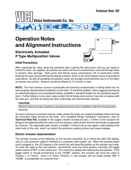
1Operation Notesand Alignment InstructionsElectrically ActuatedP Type Multiposition ValvesInitial PrecautionsAfter unpacking the valve, leave the protective tape covering the valve ports until you are ready to install the valve. As supplied, all surfaces are clean and free of contaminants, and must be kept clean to prevent valve damage. Open ports and fittings cause unnecessary risk of particulate matter entering the valve and scratching the sealing surfaces, which is the most frequent cause of premature valve failure. As with all sampling and selector valves, we strongly recommend the use of in-line filters at sample entry points. Streams should be filtered to 10 microns or less.NOTE: The most common source of particulate and chemical contamination is tubing which has not been properly cleaned before installation on the valve. T o avoid this problem, Valco suggests purchasing our electrolytically pre-cut and polished tubing, available in standard lengths for any plumbing require-ment. If other tubing is to be used, make certain that all tubing ends are burr-free and cut square with the tube axis, and that all tubing has been chemically and mechanically cleaned.CAUTION:Failure to observe proper cleanliness procedures during valve installation voids the manufacturer’s warranty.T o insure minimum connection volume, make certain the tubes are seated completely before forming the one-piece Valco ferrule on the tube. (For complete fittings installation instructions, refer to Technical Note 503, available in the support section of .) If there is ever occasion for fittings to be tightened while the valve is off the actuator, make certain that the valve body is supported by a wrench. (An adjustable open variety is suitable.) Failure to do so can apply a side-loading of the valve body to the rotor, which can distort the polymeric sealing surface and cause leakage.Electric Actuator ImplementationThe actuator consists of the following: (a) the actuator assembly, (b) a control box with LED display,and (c) a 20-conductor cable for interface to a computer, data system, etc. When the actuator power cord is plugged in, the LED display in the control box will show the position of the actuator and valve.T o move the valve to the next position, momentarily move the three position (normally off) toggle switch toward “STEP” on the control box. The control box display will indicate the new position. If the toggle switch is moved momentarily to the “HOME” position, the actuator will move the valve to Position 1, or “Home”. Once it is “home” (Position 1), the actuator will not rotate another 360° if“HOME” is accidentally hit a second time.Technical Note 702Valco Instruments Co. Inc.Using the interface cable supplied, any of these operations may also be performed by a computer or data system with the capacity to provide external events control. The computer or data system input/ output signal must be either negative true logic or a contact closure. Chapter 3 of the Multiposition Electric Actuator Instruction Manual, available in the support section of , contains more detailed information on this subject.Valve AlignmentWhen the valve arrives from the factory installed on an actuator, it is accurately aligned and ready for use. However, anytime the clamp ring on the actuator is loosened, as when removing the valve from the actuator for mounting through an instrument panel or oven wall, the valve and actuator must be realigned so that the internal ports and flow passages on the rotor intersect properly. (See Causes of Misalignment, Section 1, below.)CAUTION:Before removing the valve from the actuator, mark the factory alignment position of the valve.Closemount: Make temporary registration marks on the face of the valve where it lines upwith the slot in the clamp ring on the actuator.Standoff: Make temporary registration marks on the standoff tube where it lines up withthe slot in the black anodized clamp ring on the actuator. DO NOT remove the valve fromthe standoff assembly.When this mark is lined up with the slot during reassembly, the factory alignment will be approxi-mately reproduced, as long as the valve and the actuator remain in their original positions. Chromatographic Symptoms of Misalignment1. Loss of flow or blocked flowWhen the valve body, rotor, and actuator are not in proper alignment, the ports of the valve do not completely intersect the engravings on the valve rotor. Often flow is cut to all positions, but a slight misalignment might eliminate flow from ports on one side of the valve only. In liquid applications, blocked flow may cause a pressure buildup, leading to pump shutdown or failure of other components. T o confirm that misalignment is the problem, use a rotometer or a line placed into liquid to observe the momentary flow between positions as the actuator cycles the valve.2. Mixing of samplesIn some configurations with large ports and their corresponding large engravings which are very close together, poor alignment can cause mixing of samples even when a flow restriction has not been observed. This may be manifested as “ghost” peaks or poor reproducibility.Causes of Misalignment1. Removal of valve from actuator for mountingAs referred to earlier, mounting valves through a bracket or oven wall requires that the valve or valve/ standoff assembly be separated from the actuator. In the case of a valve on a standoff, this is accomplished by using a 9/64 hex driver to loosen the socket head screw (HWSC-SC8-8B) in the black anodized clamp ring (CR3) on the actuator (Figure 3). For valves utilizing a closemount assembly, the removal is accomplished by using a 7/64 hex driver to loosen the socket head screw (HWSC-SC8-8TDH) in the clamp ring (CR11) on the actuator (Figure 4). Any time these screws have been loosened, the alignment of the valve after replacement on the actuator should be checked.The chances of proper alignment after reassembly are greatly enhanced by following the suggestion in the CAUTION note above.232. Shock from heavy or continuous useOccasionally, when valves are used in applications requiring a high duty cycle, wear or shock can cause the screw and clamp ring to loosen. Instrument vibration may have the same effect. This allows the standoff to move, causing inaccurate rotor rotation. The most obvious symptom is an observable movement of the standoff, valve, or actuator, which normally do not move when the valve is actuated.Alignment ProcedureCAUTION:The alignment procedures for air actuated and electrically actuated valves are not the same.For an air actuated valve, see Technical Note 701, Operation Notes and Alignment Instructions,Air Actuated Multiposition Valves, found in the support section of .DescriptionThe valve will have either one (SD and SC) or two (SF , ST , and STF) rows of ports evenly spaced around the circumference of the body. See Figure 1. In addition there will be one (SD and SF) or two (SC, ST, and STF) “common” ports offset to either side of these rows. With the valve close to you and the actuator away, Position 1 falls to the left of or counterclockwise from the common port(s). The rotor will have either one or two flow passages appearing as engraved rings around the seal, which intersect the common port(s). Flow passages perpendicular to the ring(s) connect the ring(s) to the selected port(s).POSITION 1POSITION 1POSITION 1 (2 ports)POSITION 1POSITION 1POSITION 2 (2 ports)POSITION 2POSITION 2POSITION 2POSITION 2SDConfiguration SC Configuration SF ConfigurationENGRAVED RING PERPENDICULARENGRAVING STF ConfigurationSTConfiguration PERPENDICULARENGRAVING ENGRAVED RING PERPENDICULARENGRAVING ENGRAVED RINGPERPENDICULARENGRAVING ENGRAVED RING PERPENDICULARENGRAVING ENGRAVED RINGALIGNMENT INLETALIGNMENT INLET ALIGNMENT INLET ALIGNMENT INLETALIGNMENT INLET Figure 1:Typical P-type multiposition valve bodies and sealsBasically, this alignment procedure is a way of centering the perpendicular engraving on the selected port by determining the point at which flow begins (when the engraving is just beginning to intersect the port) and the point at which flow ends (when the engraving has ceased to intersect the port), and centering the rotor between those two points.1.Plug the actuator in. If the position indicator doesn’t read “1”, flip the switch to the HOME position.2.Place the valve or valve/standoff assembly on the actuator. By convention, the factory alignmentplaces the common port(s) at 12 o’clock. Re-orienting the standoff or the slotted coupling (in closemount applications) on the square drive of the actuator allows three other possibilities.For a valve on a standoff (Figure 2), make sure the standoff butts all the way against the actuator so that the drive mechanism is completely engaged. Tighten the HWSC-SC8-8B screw in the CR3 clamp ring enough to keep the standoff from falling out when it is released, but make sure it is loose enough to allow the assembly to be turned during the alignment procedure.For a closemount valve (Figure 3), make sure that the ends of the pin in the rotor are engaged by the slots of the coupling. Tighten the HWSC-SC8-8TDH screw in the CR11 clamp ring enough to keep the valve from falling out when it is released, but make sure it is loose enough to allow the valve to be turned during the alignment procedure.3.Establish a flow of clean gas (50 psi is adequate) into the port offset away from the actuator. Thisport, called the alignment inlet in Figure 1, will be the designated inlet throughout this procedure.STANDARDELECTRIC ACTUATORHWSC-SC8-8TDHSCREWSCR11CLAMP RINGSLCSLOTTEDCOUPLINGVALVE HWSC-SC8-8TDHSCREWFigure 3: Closemount assembly connecting actuator and valve454.With the valve closest to you and the actuator away from you, grip the valve and rotate it (theactuator keeps the rotor fixed) until gas flows from the port to the left of or counterclockwise from the alignment inlet. This port corresponds to Position 1. (See Figure 1)NOTE: When listening for flow, it is helpful if the fittings are removed from the port under consideration but left in the adjacent ports. If all the fittings have been removed, install a loop connecting the two adjacent ports to better isolate the sound of the flow.5.Grip the valve and rotate it counterclockwise a few degrees past the point where flow stops. Thissets up a “staging area” for the approach to Position 1.6.Slowly rotate the valve clockwise until the first traces of flow are heard from the Position 1 port.(The first port to the left of the alignment inlet.)7.While holding the valve steady, use a soft pencil or inkmarker to make a mark on the standoff correspond-ing to the slot in the actuator clamp ring. (Figure 4)This slot makes a clear fixed reference point forobserving relative rotational positions. In the case ofa closemount valve, make this mark on the valve body.8.Continue the slow manual clockwise rotation of thevalve body through the point of peak flow andbeyond until the flow stops or is barely audible, as inStep 6.9.Make another mark as in Step 7. (Figure 4)10.Make a third pencil mark halfway between the firsttwo and rotate the valve counterclockwise until thismidway mark is reached. (Figure 4)11.While holding the valve steady, firmly tighten the clamp ring screw. The rotor should be properlypositioned at the point of maximum flow when the actuator is stepped to the next position.Congratulations, the procedure is complete. It is a good idea to cycle the valve through all positions to be certain everything is functioning properly. In some cases it is possible to do an additional check by simply looking down the fitting detail and into the port as the valve is stepped from position to position. If it is a valve which has a relatively short distance from the bottom of the detail to the internal taper, the engraved “dimples” on the seal are visible as they come into alignment with the port.Consult the factory if additional help is needed.CLAMP RING SCREW Figure 4: Marking valve or standoff during alignment procedure®®North America, South America, and Australia/Oceania contact:Europe, Asia, and Africa contact:Valco Instruments Co. Inc.VICI AG International Cheminert ® and VICI ® are registered trademarks of Valco Instruments Co. Inc. and VICI AG P .O. Box 55603Houston, TX 77255Sales:(800) 367-8424Tech:(713) 688-9345Fax:(713)**********************Parkstrasse 2CH-6214 Schenkon Switzerland Phone:+41 41 925 6200Fax:+***********************TN-702 12/00Figure 5:P type multiposition valve port conventions and schematic flow diagrams(Port designations for Positions 1 and 2 are applicable to multiposition valves on standard electric actuators only)SF Flow-Through ST Trapping STF Trapping/Flow-ThroughPOSITION 1INLETPOSITION 2INLETS OUTLETS OUTLET OF SELECTED STREAM。
控制阀F96说明书
四种流量模式可任选(适用于 63650/73650/93650)
模式 名称
说明
出水流量达到设定流量且时间到达设定再生时间时 A-01 流量延滞型
引发再生或冲洗
A-02 流量即时型 出水流量达到设定流量时,立即引发再生或冲洗
可设定最大间隔再生天数(适用于 53650/63650/73650/93650)
远程控制输入
该端口可接收有源信号,与 PLC、电脑等配合使用,可远距离操作控 制阀。(应用见图 3-11) 带泄压端口
工位切换过程中信号开启,到位后信号关闭(相当于信号输出端口的 b-02)。主要用于采用增压泵供水的系统,电机切换时将进水管与控制阀间 的压力泄掉,以保证阀切换过程中水泵及控制阀的安全运行。(应用见图 3-10) 各参数可根据需要修改
单位 h:m
/ m3 D / min:sec min:sec min:sec min:sec min:sec min:sec min:sec D / /
出厂默认值 当前值 A-01 400.0 03 02:00 10:00 10:00 60:00 01:00 45:00 05:00 10:00 30 b-01 4.194
2、产品特点
结构简单密封可靠 采用高平面度、耐腐蚀的端面密封片启闭,密封可靠;集运行、反洗、
吸盐+慢洗、正洗和盐箱补水等软化全过程功能于一体。 单罐型控制阀再生时不出水
盐箱补水由电动球阀控制
盐箱补水由电动球阀控制,在运行的同时补水,缩短了再生周期。 在运行的同时补水,所以浮动床控制阀补的是软水,固定床控制阀补 的是硬水。
上电全屏图标全亮时,同时有效按“ ”键与“ ”键 2 秒以上,可 进入型号设置界面。按“ ”或“ ”键可选择所需要的型号,再按“ ” 键保存设置的型号。重新上电全屏亮后,再显示型号。 互锁功能
比例阀中文说明书

质量
约 250g(无附属品){ITV1000}
约 350g(无附属品){ITV2000}
约 620g(无附属品){ITV3000}
注1) 输出压力 0.1MPa 规格最大供给压力为 0.2MPa。
注2) 超出规格范围时,会发生破损,请注意。
3
■ 配线方法 电缆与本体的端子连接时,请以下记的形式进行配线。
8
1
各部分名称
UP 键(△键) 设定键(SET 键) DOWN 键(▽键)
显示用 LED
SUP 接口
配线电缆接线端子
外形尺寸
安装托架 (选配)
压力表用接口
外形尺寸
OUT 接口 安装孔
安装孔 右弯出线型电缆接线端子 (4 芯)
安装孔
安装托架 (选配)
直线出线型电缆接线端子 (4 芯)
安装托架 (选配)
3. 未使用显示输出时,因可能导致误动作,请注意不要将显示输出端子与其他的电线相接触。 4. 本产品,在出厂前已经对各项规格参数进行了调整。请顾客一定避免无目的的拆卸,零件的拆装等,以
防导致故障。 5. 为避免干扰信号引起的误动作,请执行下述对策。
1)请在交流电源线中加入在线滤波器,除去电源噪声。 2)请尽量将电动机及动力电源线等强电设施,同本产品及与本产品相联的配线相隔离,使本产品不受 干扰信号的影响。 3)针对诱导负载(诸如电磁阀,继电器等),请一定实施负载缓冲对策。 6. 由于右弯出线型电缆端子不能回转,请绝对不要任意旋转端子。
SET 键,就设定了键锁定状态。
(若按▽键,即取消上述操作)
(取消操作)
②设定键锁定 ①持续按 2 秒以上
5
■ 最小压力/最大压力的调节 本产品可针对输入信号进行最小压力及最大压力的调节,能以最小压力 0~50%(F.S.),最大压力 100~ 10%(F.S.)的范围进行调节。
多路阀使用手册
朗诚电子有限公司 一系列的通用服务电子阀门说明书

% ^ # )Features• Welded core tube provides higher pressure ratings •Reliable, proven design with high flows •Small poppet valves for tight shutoff•Wide range of elastomers for specialty service applications•Mountable in any position• T apped mounting holes in body standardSolenoid EnclosuresNominal Ambient T emp. RangesThe nominal limitation of 32°F (0°C) is advisable for any valve that might contain moisture (water vapor). AC: -13˚F to 131˚F (-25˚C to 55˚C)DC: -13˚F to 104˚F (-25˚C to 40˚C)-13˚F to 131˚F (-25˚C to 55˚C)Note: Max ambient for explosionproof (EF) is 125˚F (52˚C) for AC, 131˚F (55˚C) for DC.Optional: For AC, the max. ambient temperature is140˚F (60˚C) with Class H coil (with or without prefix EF)Refer to Engineering Section for details.ApprovalsCSA certified. UL listed, as indicated. Safety Shutoff Valves FM approved. Meets applicable CE directives.Refer to Engineering Section for details.Standard:Watertight, Types 1, 2, 3, 3S, 4, and 4X.Optional:Explosionproof and Watertight, Types 3, 3S, 4, 4X, 6, 6P , 7, and 9.(To order, add prefix “EF” to catalog number)See Optional Features Section for other available options.431OptionsMounting bracket (suffix MB)Quarter-turn manual operator with screw slot (suffix MS)Panel mount (prefix GP for conduit; consult ASCO for other electrical connections )Vacuum service (suffix VVM, VVH; see Vacuum Section for more details.)Oxygen service (suffix N)Silicone Free (suffix SF)Elastomers:Viton (suffix V), Ethylene Propylene (suffix E), Neoprene (suffix J), Teflon (suffix T), Low Temp NBR (suffix A)Note: For suffix A, Fluid temp. range -40˚F to 167˚F only for valves with 10.1, 17.1, 11.6, and 22.6 watt coils.Refer to Engineering Section for fluid and temperature compatibility.Specifications (English units)x Cast UR disc supplied as standard, limits min. ambient temp. to 32˚F (0˚C); G = General Purpose Valve, H= Safety Shutoff Valvex Cast UR disc supplied as standard, limits min. ambient temp. to 32˚F (0˚C); G = General Purpose Valve, H= Safety Shutoff ValveDimensions: inches (mm)34。
Caleffi 6000 Series LEGIOMIX电子混合阀说明书
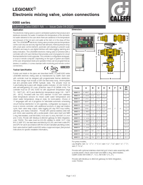
Furnish and install on the plans and described herein, a Caleffi 6000 series electronic mixing valve as manufactured by Caleffi. Each valve with controller must be designed with programmable thermal disinfection. The valve design must include a DZR low-lead brass body, chrome-plated M hydraulic seals. The actuator must be 3-wire floating fail-in-place with integral position indicator, 24 VAC 50/60 Hz with self-extinguishing VO cover, protection class IP 65 (NEMA 4/4X). The CALEFFIdesired. In addition, it comes standard with monitoring and remote control LEGIOMIX ®Electronic mixing valve, union connectionsProvide with optional stainless steel inlet port check valve assembly with a acetal plastic check valve insert and NBR o-ring, field installed. Caleffi codes NA10366 (1", 1¼"), NA10367 (1½, 2").Provide with Modbus-to-BACnet gateway for BAS integration, code 755052.For press models,Lay lengths: size ¾" - 5 9/16" ; 1"-5 ½"; size 1 ¼"- 7 ¾"; size 1 ½"- 7 3/8"; size 2"-10 ¾".We reserve the right to change our products and their relevant technical data, contained in this publication, at any time and without prior notice. Contractors should request production drawings if prefabricating the system .Job name ______________________________________Job location ______________________________________Engineer ______________________________________Mechanical contractor ________________________________Contractor’s P.O . No. ________________________________Size________________________________________Quantity ________________________________________Approval ________________________________________Service ________________________________________Tag No. ________________________________________(1) T o ensure stable operation and a ± 3° F accurate temperature control Minimum flow rate is 0 gpm when recirculation flow rate is greater than or equal to the valve size minimum flow rating.(2) Suggested maximum flow rate for optimum modulating control (at 7.5 psid pressure drop).(3) Maximum recommended differential pressure is 20 psid to ensure stable operation and accurate temperature control.Furnish and install on the plans and described herein, a Caleffi 6000 series electronic mixing valve as manufactured by Caleffi. Each valve with controller must be designed with programmable thermal disinfection. The valve design must include a DZR low-lead brass body, chrome-plated low-LEGIOMIX ®Electronic mixing valve, ANSI 150 Flanged1. LEGIOMIX digital controller2. Mixing valve3. Mixing valve 24V 3-wire actuator4. Mixed outlet water temperature sensor5. Return water (recirculation) temperature strap-on sensor6. Mixed outlet water temperature gauge8. Removable operating leverWe reserve the right to change our products and their relevant technical data, contained in this publication, at any time and without prior notice. Contractors should request production drawings if prefabricating the system.Job name ______________________________________ Job location ______________________________________ Engineer ______________________________________ Mechanical contractor ________________________________Size ________________________________________ Quantity ________________________________________ Approval ________________________________________ Service ________________________________________LEGIOMIX ®Electronic mixing valve, sizing/selectionCALEFFIWe reserve the right to change our products and their relevant technical data, contained in this publication, at any time and without prior notice. Contractors should request production drawings if prefabricating the system .Job name ______________________________________Job location ______________________________________Engineer ______________________________________Mechanical contractor ________________________________Contractor’s P.O . No. ________________________________Representative ________________________________Size________________________________________Quantity ________________________________________Approval ________________________________________Service ________________________________________Tag No. ________________________________________Notes ________________________________________Notes:LEGIOMIX Valve Sizing & Selection1) Obtain the maximum GPM (demand) of domestic hot water from project documentation.2) Select valve size which has GPM "design" (at 7.5 PSID pressure drop) that is = or > than the project maximum GPM. 7.5 PSID is the suggested maximum pressure drop across the valve for optimum modulating control. Occasional flow rate greater than the "design" value, even flow rates at pressure drops up to 20 PSID, are acceptable for intermittent flow but should not be used as the basis for valve sizing and selection.3) The "FPS in xx" pipe " velocity values are shown for reference only. Different types of pipe can handle different velocities. For example, the Uniform Plumbing Code velocity guideline for 140 °F water in copper pipe is 5 FPS which equates to 28.6 GPM in a 1-1/2" pipe. A 1" LEGIOMIX valve would be the best choice for that flow rate and pipe type.Because of the high flow capacity of the LEGIOMIX ball valve, it is not uncommon for the valve to be installed in piping that is one or two sizes larger than the valve body.1) GPM minimum for guaranteed stable control; size the recirculation pump to deliver at least this flow rate.2) GPM at 7.5 PSID, suggested maximum flow for optimum modulating control 3) GPM maximum @ 20 PSID; max short term pressure drop and flow for the valve 4) GPM per UPC section A 6.1 is 10 fps. Applicable using stainless steel ornon-metallic pipe (i.e. Uponor recommends 12 ft/sec. maximum velocity for hot and cold domestic water systems using Uponor AquaPEX pipe and ProPEX fittings).equal. (See product instructions for specific installation information.)CALEFFIWe reserve the right to change our products and their relevant technical data, contained in this publication, at any time and w ithout prior notice. Contractors should request production drawings if prefabricating the system .Job name ______________________________________Job location ______________________________________Engineer ______________________________________Mechanical contractor ________________________________Contractor’s P.O . No. ________________________________Representative ________________________________Size________________________________________Quantity ________________________________________Approval ________________________________________Service ________________________________________Tag No. ________________________________________Notes ________________________________________ThermoSetter ™ Recirculationthermal balancing valve for disinfectionMaterialsBody: DZR low-lead brass Adjustable cartridge: stainless steel & copper Springs: stainless steel AISI 302 (EN 10270-3) Hydraulic seals: peroxide-cured EPDM Adjustment knob: ABS Performance:Suitable fluid: waterMax. working pressure: 230 psi (16 bar)Max. differential pressure: 15 psi (1 bar)Max. inlet temperature: 195°F (90°C)Adjustment temperature range: 95-140°F (35–60°C)Flow Cv (Kv) max: 2.1 (1.8)Flow Cv (Kv) min: 0.23 (0.2)Flow Cv (Kv) design: 0.52 (0.45)D Stem diameter: 0.35" (9 mm)Technical specifications of insulation Materials: closed cell expandedPE-X Thickness: ½ inch (13 mm)Density: -internal part: 1.9 lb/ft³ (30 kg/m³) -external part: 5.0 lb/ ft³ (80 kg/m³)Thermal conductivity (DIN52612): - at 32°F (0°C): 0.82 BTU · in/hr · ft² · °F (0.0345 W/(m · K)) - at 105°F (40°C): 0.94 BTU · in/hr · ft² · °F (0.0398 W/(m · KCoefficient of resistance to the diffusion of vapor: > 1,300Working temperature range: 32–212°F (0–100°C)Flammability (ASTM D 635): Class VO Certifications:1. Complies with codes IPC, IRC, UPC and NPC. ICC-ES certified to NSF/ANSI 61 (180°F/82°C Commercial Hot), file PMG-1512. 2. NSF/ANSI 372, low lead certified by ICC-ES, file PMG-1360.NSF 61Certifications1. ASSE 1070/CSA B125.3-2012, certified by ICC-ES, file PMG-1358.2. NSF/ANSI 372, Drinking Water System Components-Lead Content Reduction of Lead in Drinking Water Act, California Health and Safety Code 116875 S.3874, Reduction in Drinking Water Act, Vermont Act 193 - The Lead in Plumbing Supplies Law andMaryland’s Lead Free Law HB.372, certified by ICC-ES, file PMG-1360.3. Complies with codes IPC, IRC, UPC and NPC.The Caleffi SinkMixer anti-scald thermostatic mixing valve is intended for use in under sink and under counter applications in accordance with installation rules and indications specified in ASSE 1070 standards. The SinkMixer is used to prevent accidental scalding with the outlet water temperature properly adjusted using a thermometer Materials:Valve body, regulating spindle, spring holder, cold inlet union nut: forged low-lead brass (< 0.25% lead content)Internal shutter: polysulfone Hot inlet strainer: AISI 304 stainless steel Spring: AISI 302 stainless steel Seals: Peroxide-cured EPDM Cover: ABS white Mounting bracket and adjustment key: Polyamide NylonWe reserve the right to change our products and their relevant technical data, contained in this publication, at any time and without prior notice. Contractors should request production drawings if prefabricating the system .Job name ______________________________________Job location ______________________________________Engineer ______________________________________Mechanical contractor ________________________________Contractor’s P.O . No. ________________________________Representative ________________________________Size________________________________________Quantity ________________________________________Approval ________________________________________Service ________________________________________Tag No. ________________________________________Notes ________________________________________。
GOYEN RCA3 电磁阀电子阀门说明书
GOYENRCA3 SOLENOID PILOT VALVESRCA3D with flying lead connectionspade connectionRCA3D withDIN43650A connectionRCA3D with conduit entry connectionPRODUCT LEAFLETSOLENOID PILOT VALVESGOYEN - RCA3ORDER CODE AND ELECTRICAL CHARACTERISTICSRCA3D0 Series = 1/8” NPT MODEL CONNECTION TYPE PROTECTION CLASS VOLTAGEPOWER RCA3D0–300DIN 43650A IP65200/240 V 50/60 Hz 17.4/22.6 V A RCA3D0–301DIN 43650A IP65100/120 V 50/60 Hz 15.2/19.7 V A RCA3D0–302DIN 43650A IP6524 V 50/60 Hz 23.1/17.2 V A RCA3D0–303DIN 43650A IP65110 V DC 24 W RCA3D0–304DIN 43650A IP6548 V DC 20 W RCA3D0–305DIN 43650A IP6524 V DC 20 W RCA3D0–306DIN 43650A IP6512 V DC20 W RCA3D0–310Conduit (M20 × 1.5)IP31200/240 V 50/60 Hz 17.4/22.6 V A RCA3D0–311Conduit (M20 × 1.5)IP31100/120 V 50/60 Hz 15.2/19.7 V A RCA3D0–312Conduit (M20 × 1.5)IP3124 V 50/60 Hz 23.1/17.2 V A RCA3D0–313Conduit (M20 × 1.5)IP3124 V DC 20 W RCA3D0–314Conduit (M20 × 1.5)IP3112 V DC20 W RCA3D0–320Conduit (½” NPSC)IP31200/240 V 50/60 Hz 17.4/22.6 V A RCA3D0–321Conduit (½” NPSC)IP31100/120 V 50/60 Hz 15.2/19.7 V A RCA3D0–322Conduit (½” NPSC)IP3124 V 50/60 Hz 23.1/17.2 V A RCA3D0–323Conduit (½” NPSC)IP3124 V DC 20 W RCA3D0–324Conduit (½” NPSC)IP3112 V DC20 W RCA3D0–330Screw / spade NA 200/240 V 50/60 Hz 17.4/22.6 V A RCA3D0–331Screw / spade NA 100/120 V 50/60 Hz 15.2/19.7 V A RCA3D0–332Screw / spade NA 24 V 50/60 Hz 23.1/17.2 V A RCA3D0–333Screw / spade NA 240 V DC 24 W RCA3D0–334Screw / spade NA 110 V DC 24 W RCA3D0–335Screw / spade NA 48 V DC 20 W RCA3D0–336Screw / spade NA 24 V DC 20 W RCA3D0–337Screw / spade NA 12 V DC20 W RCA3D0–340Flying Lead IP64200/240 V 50/60 Hz 17.4/22.6 V A RCA3D0–341Flying Lead IP64100/120 V 50/60 Hz 15.2/19.7 V A RCA3D0–342Flying Lead IP6424 V 50/60 Hz 23.1/17.2 V A RCA3D0–343Flying Lead IP6424 V DC 20 W RCA3D0–344Flying LeadIP6412 V DC20 WNotes: RCA3D0-305 is an RCA3D remote pilot with 1/8˝ NPT threads and a 24 V DC DIN43650A connection.PRODUCT LEAFLETSOLENOID PILOT VALVESGOYEN - RCA3ORDER CODE AND ELECTRICAL CHARACTERISTICSRCA3D1 Series = 1/8˝ BSPP MODEL CONNECTION TYPE PROTECTION CLASS VOLTAGEPOWER RCA3D1–300DIN 43650A IP64200/240 V 50/60 Hz 17.4/22.6 V A RCA3D1–301DIN 43650A IP64100/120 V 50/60 Hz 15.2/19.7 V A RCA3D1–302DIN 43650A IP6424 V 50/60 Hz 23.1/17.2 V A RCA3D1–303DIN 43650A IP64110 V DC 24 W RCA3D1–304DIN 43650A IP6448 V DC 20 W RCA3D1–305DIN 43650A IP6424 V DC 20 W RCA3D1–306DIN 43650A IP6412 V DC20 W RCA3D1–310Conduit (M20 × 1.5)IP31200/240 V 50/60 Hz 17.4/22.6 V A RCA3D1–311Conduit (M20 × 1.5)IP31100/120 V 50/60 Hz 15.2/19.7 V A RCA3D1–312Conduit (M20 × 1.5)IP3124 V 50/60 Hz 23.1/17.2 V A RCA3D1–313Conduit (M20 × 1.5)IP3124 V DC 20 W RCA3D1–314Conduit (M20 × 1.5)IP3112 V DC20 W RCA3D1–320Conduit (½” NPSC)IP31200/240 V 50/60 Hz 17.4/22.6 V A RCA3D1–321Conduit (½” NPSC)IP31100/120 V 50/60 Hz 15.2/19.7 V A RCA3D1–322Conduit (½” NPSC)IP3124 V 50/60 Hz 23.1/17.2 V A RCA3D1–323Conduit (½” NPSC)IP3124 V DC 20 W RCA3D1–324Conduit (½” NPSC)IP3112 V DC20 W RCA3D1–330Screw / spade NA 200/240 V 50/60 Hz 17.4/22.6 V A RCA3D1–331Screw / spade NA 100/120 V 50/60 Hz 15.2/19.7 V A RCA3D1–332Screw / spade NA 24 V 50/60 Hz 23.1/17.2 V A RCA3D1–333Screw / spade NA 240 V DC 24 W RCA3D1–334Screw / spade NA 110 V DC 24 W RCA3D1–335Screw / spade NA 48 V DC 20 W RCA3D1–336Screw / spade NA 24 V DC 20 W RCA3D1–337Screw / spade NA 12 V DC20 W RCA3D1–340Flying Lead IP64200/240 V 50/60 Hz 17.4/22.6 V A RCA3D1–341Flying Lead IP64100/120 V 50/60 Hz 15.2/19.7 V A RCA3D1–342Flying Lead IP6424 V 50/60 Hz 23.1/17.2 V A RCA3D1–343Flying Lead IP6424 V DC 20 W RCA3D1–344Flying LeadIP6412 V DC20 WNote: RCA3D1-331 is an RCA3D remote pilot with 1 8˝ BSPP threads and 110/240 V AC spade screw coil.PRODUCT LEAFLETSOLENOID PILOT VALVESGOYEN - RCA3RCA3DM - HOW TO ORDERRCA – Pilot valve – Remote-controlled air Coil series 3 – Goyen ‘Q’ coil Valve type3 – 1/8” Pipe threadPilot sizeBody styleDM – Male inlet, R 1/8” thread, suits all Series 4 RCAC valves-103M D 3A C R FLOWMAXIMUM WORKING PRESSURE MINIMUM WORKING PRESSURE TEMPERATURE MIN TEMPERATURE MAX FLUID MEDIANITRILE VITONNITRILEVITON0.32 Cv/0.27 Kv 860 kPa/125 psi0 kPa/0 psi−40°C/−40°F −29°C/−20°F82°C/180°F 232°C/450°FAir or inert gasPRODUCT PERFORMANCEDIN SOCKET CONNECTOR Pg9 connection (cable entry)DIN SOCKET SPECIFICATION EN175301 - 803 (previously DIN 43650A) / A/ISO 4400DIN SOCKET OPTIONAL 94/9/CE ATEX II 3GD T6ISOLATION CLASS DIN SOCKET VDE 0110 - 1/89DIN SOCKET PROTECTION IP65 EN60529ELECTRICAL CHARACTERISTICSMODEL TYPE CONNECTION TYPE PROTECTION CLASS VOLTAGEPOWER COLOUR 300QR DIN 43650A IP64200/240 V 50/60 Hz 17.4/22.6 V A Grey 301QR DIN 43650A IP64100/120 V 50/60 Hz 15.2/19.7 V A Grey 302QR DIN 43650A IP6424 V 50/60 Hz 23.1/17.2 V A Grey 303QR DIN 43650A IP64110 V DC 24 W Grey 304QR DIN 43650A IP6448 V DC 20 W Grey 305QR DIN 43650A IP6424 V DC 20 W Grey 306QR DIN 43650A IP6412 V DC20 W Grey 310QD Conduit (M20 × 1.5)IP31200/240 V 50/60 Hz 17.4/22.6 V A Green 311QD Conduit (M20 × 1.5)IP31100/120 V 50/60 Hz 15.2/19.7 V A Green 312QD Conduit (M20 × 1.5)IP3124 V 50/60 Hz 23.1/17.2 V A Green 313QD Conduit (M20 × 1.5)IP3124 V DC 20 W Green 314QD Conduit (M20 × 1.5)IP3112 V DC20 W Green 320QD Conduit (½” NPSC)IP31200/240 V 50/60 Hz 17.4/22.6 V A Green 321QD Conduit (½” NPSC)IP31100/120 V 50/60 Hz 15.2/19.7 V A Green 322QD Conduit (½” NPSC)IP3124 V 50/60 Hz 23.1/17.2 V A Green 323QD Conduit (½” NPSC)IP3124 V DC 20 W Green 324QDConduit (½” NPSC)IP3112 V DC20 WGreenSUITABLE FORRCAC20T3, RCAC20ST3, RCAC20DD3, RCAC20FS3, RCAC25T3, RCAC25DD3, RCAC25FS3 dust collector valves only.INSTALLATIONEnsure o-ring is in place on diaphragm valve cover. Gripping the shroud, hand tighten 3DS pilot valve onto cover of diaphragm valve. For reliable operation, ensure supply voltage is within –10% and +15% of rated solenoid voltage. Solenoid is free to rotate on pilot valve. 3DS thread will suit 1/8 BSP T, 1/8 BSP P and 1 8 NPT ports. Replace pilot components within 1 million cycles (refer to Spare Parts). CONSTRUCTION Body: Ferrule: Armature: Encapsulation: Insulation: Seals: Shroud: OPERATION3DS–03DS–310 to3DS–300 to 3DS-306PRODUCT LEAFLETSOLENOID PILOT VALVESGOYEN - RCA3ORDER CODE AND ELECTRICAL CHARACTERISTICS3DS MODEL CONNECTION TYPE PROTECTION CLASS VOLTAGEPOWER 3DS–300DIN 43650A IP64200/240 V 50/60 Hz 23.1 V A 3DS–301DIN 43650A IP64100/120 V 50/60 Hz 19.8 V A 3DS–302DIN 43650A IP6424 V 50/60 Hz 23.1 V A 3DS–303DIN 43650A IP64110 V DC 24 W 3DS–304DIN 43650A IP6448 V DC 20 W 3DS–305DIN 43650A IP6424 V DC 20 W 3DS–306DIN 43650A IP6412 V DC20 W 3DS–310Conduit (M20 × 1.5)IP31200/240 V 50/60 Hz 23.1 V A 3DS–311Conduit (M20 × 1.5)IP31100/120 V 50/60 Hz 19.8 V A 3DS–312Conduit (M20 × 1.5)IP3124 V 50/60 Hz 23.1 V A 3DS–313Conduit (M20 × 1.5)IP3124 V DC 20 W 3DS–314Conduit (M20 × 1.5)IP3112 V DC20 W 3DS–320Conduit (½” NPSC)IP31200/240 V 50/60 Hz 23.1 V A 3DS–321Conduit (½” NPSC)IP31100/120 V 50/60 Hz 19.8 V A 3DS–322Conduit (½” NPSC)IP3124 V 50/60 Hz 23.1 V A 3DS–323Conduit (½” NPSC)IP3124 V DC 20 W 3DS–324Conduit (½” NPSC)IP3112 V DC20 WPRODUCT LEAFLETSOLENOID PILOT VALVESGOYEN - RCA3RCA3PV/3PV2 - HOW TO ORDERFLOWMAXIMUM WORKING PRESSURE MINIMUM WORKING PRESSURE TEMPERATURE MIN.TEMPERATURE MAX.FLUID MEDIA0.28 Cv/0.24 Kv 860 kPa/125 psi0 kPa/0 psi−40°C/−40°F82°C/180°FAir or inert gasPRODUCT PERFORMANCEDIN SOCKET CONNECTOR Pg9 connection (cable entry)DIN SOCKET SPECIFICATION EN175301 - 803 (previously DIN 43650A) / A/ISO 4400DIN SOCKET OPTIONAL 94/9/CE ATEX II 3GD T6ISOLATION CLASS DIN SOCKET VDE 0110 - 1/89DIN SOCKET PROTECTION IP65 EN60529ELECTRICAL CHARACTERISTICSMODEL TYPE CONNECTION TYPE PROTECTION CLASS VOLTAGEPOWER COLOUR 206SB4DIN 43650A IP6512 V DC (max. +10% supply)18 W Black 205SB4DIN 43650A IP6524 V DC (max. +10% supply)18 W Black 204SB4DIN 43650A IP6548 V DC (max. +10% supply)18 W Black 203SB4DIN 43650A IP65110 V DC (max. +10% supply)18 W Black 206SB4DIN 43650A IP6524 V 50/60 Hz (max. +10% supply)38/31 VA Black 205SB4DIN 43650A IP6548 V 50/60 Hz (max. +10% supply)41/32 VA Black 204SB4DIN 43650A IP65110/127 V 50/60 Hz (max. +10% supply)63/53 VA Black 203SB4DIN 43650AIP65220/240 V 50/60 Hz (max. +10% supply)46/37 VABlackRCA – Pilot valve – Remote-controlled air RCA3 PV 2-2 0 5Valve type3 – 1/8” Pipe thread Pilot sizePV – Male inlet, suits all RCA and RCAC main valves Body styleBlank – R1/8” thread2 – G1/4” threadThread type2 – DIN 43650 Form B connectionCoil series0 – Square DIN connector Coil connection3 Dual rating: 110V DC 18W or 220/240V 50/60Hz 46/37VA4 Dual rating: 48V DC 18W or 115V 50/60Hz 63/53VA5 Dual rating: 24V DC 18W or 48V 50/60Hz 41/32VA6 Dual rating: 12V DC 18W or 24V 50/60Hz 38/31VA Voltage optionsRemote Pilot valve RCA3PV2 – 203Valve typeBlank – 1/8”2 – 1/4” threadPilot size Blank – Pilot only 203204205206Coil seriesSee table below for coil code.。
fleck自动阀组的中文说明书
硬水经控制阀进入树脂罐,经树脂层处理 过的水通过底部的布水器,然后沿着中心 的升降管向上,再通过控制阀流出。
4
北京滨特尔洁明环保设备有限公司
5、快速清洗状态
Edited by Foxit PDF Editor Copyright (c) by Foxit Software Company, 2004 For Evaluation Only.
目录
一、产品概述
3
二、工作流程图
4
三、设备的系统说明
6
四、设备的安装和运行
7
五、设备安装示意图
8
六、流量型控制器调试步骤
9
七、时间型控制器调试步骤
10
八、故障排除
12
2
北京滨特尔洁明环保设备有限公司
Edited by Foxit PDF Editor Copyright (c) by Foxit Software Company, 2004 For Evaluation Only.
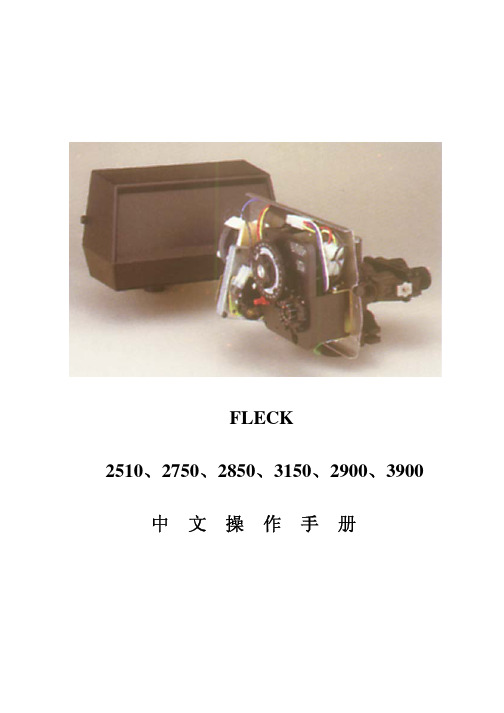
2510 2750 2850 3150 2900 3900 中文操作手册
6、盐罐注水状态
硬水经控制阀进入树脂罐向下,经过树脂层后进 入布水器沿升降管向上,最后通过控制阀排水口 排出。其流速比慢速清洗稍快,
硬水进入控制阀,在向设备供水的同时, 经注水器通过盐水阀向盐罐注水。
5
北京滨特尔洁明环保设备有限公司
系统 6
单流量计先后再生控制系统 两罐、单流量计。两罐同时供水工作,当流量计回零时,主罐开始再生。一旦主罐返回服务 供水状态,副罐开始再生。当用水需求量大时可多个系统并联工作。
系统 7
单流量计交替再生控制系统 两罐、单流量计,交替工作,交替再生系统,一罐供水服务,另一罐备用。当流量计回零后, 供水服务开始再生,备用罐开始供水服务,循环往复,一备一用。当用水需求量大时可多个 系统并联工作。
多功能水泵控制阀说明书
J745X-D 10 16 25 40 64多功能水泵控制阀使用说明书多功能水泵控制阀细分为:A类:双进双出型(DN400口径以上)B类:深井泵型(DN200以下带排气阀,大于或等于DN200建议加装排气阀)C类:立式安装型(带弹簧)D类:流量调节型(带调节丝杆)E类:标志杆型(带行程开关)F类:全行程数显装置型(带数显装置)一、用途安装在市政、建筑、钢铁、冶金、石油、化工、煤气(天然气)、食品、医药、矿山、电站、核电、水利及灌溉等领域的取水、送水、加压、潜水、污水泵房及石油、化工流体的输送系统中,融电动阀、止回阀和水锤消除器三种设备的功能于一体,能有效地提高系统安全可靠性,满足系统自动化控制要求。
二、特点1、安全可靠性高,具有速闭、缓闭以及吸能腔三种消除水锤措施,而且动作完全联锁,不会产生误动作。
2、无需操作控制,当水泵启停时,巧妙地利用阀门前后介质的压力变化来控制动力,使阀门自动按水泵操作规程的要求进行动作。
3、无需专业调试,阀门动作不受水泵扬程及流量变化的影响,适应范围广。
4、基本无需维修,寿命长。
5、节能效果明显,利用进口端的压力进入膜片下腔支撑膜片压板及阀杆的重量,阻力损失小。
三、技术参数1、公称压力:、、、、、2、最低动作压力:3、适用介质:原水、海水、污水、油品4、适用温度:0 ~ 80℃5、缓闭时间:3 ~ 120S(可调节)6、水锤峰值:≤倍水泵出口额定压力7、水泵最高反转速度:≤倍水泵额定转速8、膜片疲劳弯曲:120万次无破损四、结构(图一:结构示意图)多功能水泵控制阀由主阀和外装附件组成,主阀由阀体、膜片、阀杆组件、阀盖、主阀板、缓闭阀板、膜片座等主要零件组成,外装附件主要有控制阀、过滤器、排气阀、微止回阀、其中微止回阀是特制配件,在其止回方向设有限流孔。
图一结构示意图五、工作原理1、启闭过程示意图(水力控制正常工作过程)2、手动操作启闭在管路有压时,可手动操作控制管上的阀门和排气阀,实现阀门的手动操作启闭。
诚峰智远全自动多路阀说明书
全自动过滤阀—GA时间型(不带关闭工位)代号:CF:00(LED显示屏)北京诚峰智远科技有限公司目录一、注意事项二、产品简介三、基本说明1、控制面板功能及其意义2、阀门通电后显示屏显示3、出厂默认参数4、按键的意义5、参数查询、设定及修改6、手动功能7、显示8、保护功能9、信号输出及控制功能10、安装管路及水路试运行11、通电试运行12、控制电路功能及连接A、信号输出端口B、互锁C、泄压端口D、远程控制端口四、常见故障及其排除方法五、组件及零部件编号六、保修说明一、注意事项★确保产品安装后的正常使用,请在使用前让专业的安装或维修人员确认。
★安装时如有任何管道工程及任何电器工作都必须由专业人员完成。
★本阀门安装时需要远离强磁场,如果有变频器和水泵,变频器和水泵的连接线需要用屏蔽电缆连接。
★严禁将该阀用于不安全的或者不明水质的地方。
★过滤个过程的参数应根据工作条件的变化和出水的要求及时修正。
★使用过程中,应周期性的检测水质,以确保系统的正常运行。
★切勿将阀门靠近热源或高湿度、有腐蚀性、强磁场、强震动等环境中,亦不能将其直接暴露于室外。
★严禁将排水管和其他接头作为支撑提升或搬运系统。
★请在水温为5~50℃、水压为0.15~0.6MPa范围内使用本产品,在此范围外使用本产品所引发的故障或事故不在本公司责任及保修之列。
★如果进水压力大于0.6MPa,需在进水口端安装减压阀;进水压力低于0.15MPa 时,应在进水端加装增压泵。
★切勿让儿童接触或玩耍,不小心碰到操作键可能导致程序发生变化。
★本产品附带的电源线及电源适配器损坏时,必须更换本公司出厂的电源线及电源适配器。
二、产品概述1、主要用途适用范围主要用于水处理系统中进行过滤过程的智能化控制。
适用于家用过滤系统、泳池过滤设备、反渗透预处理系统中的过滤器等。
2、产品特点2.1 结构简单密封可靠采用高平面度、耐腐蚀的端面密封片开闭,密封可靠;集运行、反洗、正洗等全过程功能于一体。
FLECK2750多路控制阀中文使用说明书

我公司将为用户提供完善的技术服务及售后服务。
2
广州洁明水处理设备有限公司
FLECK 控制阀使用说明书
Model 2510 迷你经济型 Model 2750 经济型
投资最少 占地最省 安装简便 管理集中
适用于水质稳定,原水硬度较低或对水质要求不需很高的用户, 如小型洗衣房、补水量较稳定的锅炉房,同时也是追求高品质的家庭、 别墅用水的明智选择。
4
广州洁明水处理设备有限公司
注意:最初安装流量计后应进行检查:
FLECK 控制阀使用说明书
1、 转动手动再生阀,走一遍程序。
2、 顺时针转动程序轮或顺时针转动中心
轮,使设定的流量数对准小白点。
3、 可随时改变设定的流量。
时间的设定(*仅指带有延时功能的系统)
压下红色按扭,松开与 24 小时时间盘的啮合。转动时间盘,使
Model 2850 经济实用型 投资适中 水量充足 节约占地 便于管理
适用于中等需水量的饿宾馆饭店、洗衣房、锅炉房等。
Model 2900 动力设备伴侣型
特别加装了硬水止通阀,在还原期间自动关闭软化水出水口,保 证没有硬水通过。使锅炉运行更安全、更可靠。适用于于蒸气锅炉和 大型热水锅炉。
Model 3150 及 Model 3900 超量供水实力型
两个状态的时间,每一孔相当于 2 分钟,增减孔的数目则更改吸盐水
及慢洗时间的长短。调整时以移动第二组销子的位置来增减孔。
如何改变快洗时间的长短
定时器上第二组销子数目是控制快洗时间长短的,每增加或减少
一根销子,则增加或缩短快洗两分钟。
如何改变盐罐注水时间的长短
定时器上第三组插销子数目是控制注水时间长短的。每一孔相当
Service Manual
电动阀说明书

1.概述多回转阀门电动装置,简称为Z型电装,是阀门实现开启、关闭或调节控制的驱动设备。
Z型电装适用于闸阀、截止阀、隔膜阀、柱塞阀、节流阀、水闸门等。
可用于明杆阀,也可用于暗杆阀。
本系列电装具有功能全、性能可靠、控制系统先进、体积小、重量轻、使用维护方便等特点。
可对阀门实行远控、集控和自动控制。
广泛用于电力、冶金、石油、化工、造纸、污水处理等行业。
本产品的性能符合JB/T8528-1997《普通型阀门电动装置技术条件》的规定。
隔爆型的性能符合GB3836.1-2000《爆炸性气体环境用电气设备第1部分:通用要求》,GB3836.2-2000《爆炸性气体环境用电气设备第2部分:隔爆型“d”》及JB/T8529-1997《隔爆型阀门电动装置技术条件》的规定。
多回转电动装置按防护类型分:有户外型和隔爆型;按控制方式分:有常规型、整体型和整体调节型;按连接型式分:有转矩型、电站型和推力型。
2.型号表示方法A:带现场按钮;F:带4-20mA信号输出;S:带手动减速箱:整体型;T:整体调节型输出轴最大转圈数:阿拉伯数字表示,无数字见表1防护类型:W表示户外型;B表示隔爆型输出转速:阿拉伯数字表示,单位r/min(转/分)连接型式:T表示推力型,I表示电站型,无代号为常规转矩型额定输出转矩:阿拉伯数字表示,单位kgf·m产品型式:多回转电动装置型号示例:1.Z30I-18W:多回转电动装置,输出转矩300N·m(30kgf·m),电站型接口,输出转速18r/min,最大转圈数60,常规户外型。
2.Z45T-24B/S:多回转电动装置,输出转矩450N·m(45kgf·m),推力型接口,输出转速24 r/min,最大转圈数120,隔爆型,带手动减速箱。
3.Z120-24W/240T:多回转电动装置,输出转矩1200N·m (120kgf·m),转矩型接口,输出转速24 r/min,最大转圈数240圈,整体调节型。