沃泰斯脚踏式注脂枪QS-1800A-K
SPM凡尔体
SPM凡尔体代理:0595 - 2876 79 20(林经理)13 850713 656每种产品都有其使用年限或根据您的使用情况出现不同程度的损坏,能修的尽量修复一下,不能修的只能重新选购,找到好的供应商就是产品供货品质的保证,就是采购成本的节省,我们就是您所要找的。
近期较推荐的一下型号产品:SPM凡尔体P105743 4.5寸SPM凡尔座P105753SPM 4L20422SPM防漏油垫CN-705(运用于SPM TWS600 泵上)SPM缓冲器RP1006SPM单流阀2A25064-3″SPM柱塞盘根P100652 (夹布)SPM柱塞盘根P100195 (橡胶)BRANDT 001-081-002 Cable speed controlBRANDT 034-815-000 Heat exchanger fitting assemblyBRANDT 034-600-500 Hose assy.-HYD pump suctionBRANDT 034-600-301 Hose assy.-cooler to reservoirBRANDT 034-600-303 Hose assy.-pump to coolerBRANDT 034-600-01 Hose assy.-GaugeBRANDT 034-600-302 Hose assy.-motor return/pumpBRANDT 034-600-300 Hose assy.-pump to motorBRANDT 034-600-104 Hose assy.-open/return gaugesBRANDT 034-600-103 Hose assy.-Boost guageBRANDT 034-600-102 Hose assy.-Vacuum gaugeBRANDT振动筛HS3400的配件SPM提供适应于油田钻井、固井、测试、酸化压裂、连续油管及砂控作业、海洋平台等所需的各种高压组合管汇、流体控制元件、以及各类压裂泵等产品。
配置与技术指标

表面处理工艺:脱脂-电动抛丸-静电喷塑
安装方式:移动式
执行标准:GB19272-2011《室外健身器材的安全通用要求》
1、箱体部件由支撑方管50mmX100mm×3.0mm^框架方管40πιπιX40mm×3.Omm>底撑20mm×40mm×2.Omm、底脚40mm×40mmX3.Omm等组焊,外包覆一层3mm钢板。
7、钢材符合GB/T3091-2001标准要求,完全满足器材的使用强度。焊接件经二氧化碳气体保护焊焊接而成,严密牢固,焊缝美观,无漏焊、虚焊、包渣、裂纹等缺陷;表面采用静电喷塑表面光滑平整,色泽均匀,结合牢固;
8.产品符合GB19272-2011《室外
健身器材的安全通用要求》;注:①已提供具有相应资质的检测机构出具的检测报告和NSCC认证证书及确认函(以上证件已加盖生产厂家鲜章);②已提供NSCC国体官网查询截图备查;
QF-LJ033
休闲平凳
(休闲椅)
套
360
1300
468000
外形尺寸:1240*360*430mm
主要材料:钢管
主要承载立柱尺寸:Φ114mm×
3.Omm
主要承载横梁尺寸:60×40×
3.Omm
表面处理工艺:脱脂-电动抛丸-静电喷塑安装方式:直埋
执行标准:GB19272-2011《室外健身器材的安全通用要求》
2、立臂部件由立臂管150mmX150mm×4.Omm^法兰板、耳板组焊。
3、后拉杆部件由拉管50mm×50mmX3.Omm、套管138mmX3.Omm组焊。
4、探臂部件由探臂管15OninlX15OnlmX4.0mm、连接板、套管中38mm×3.Omm等组焊。
QS-2200A电动注脂枪
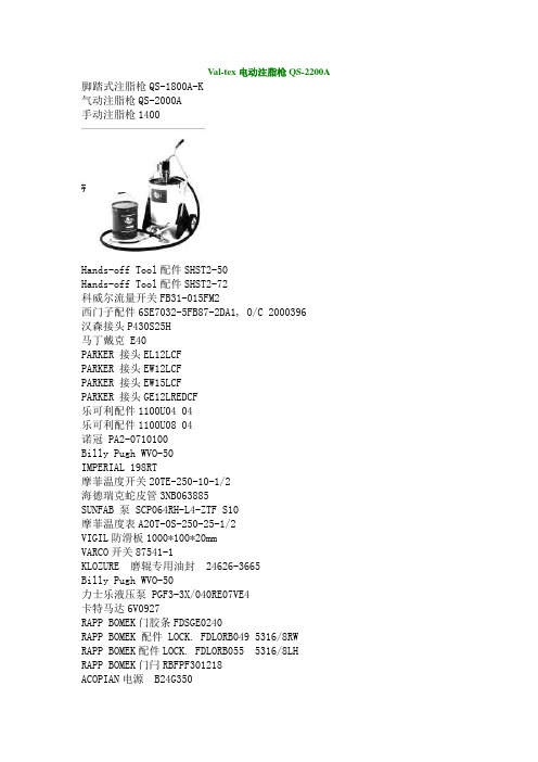
Val-tex电动注脂枪QS-2200A 脚踏式注脂枪QS-1800A-K气动注脂枪QS-2000A手动注脂枪1400Hands-off Tool配件SHST2-50Hands-off Tool配件SHST2-72科威尔流量开关FB31-015FM2西门子配件6SE7032-5FB87-2DA1, O/C 2000396汉森接头P430S25H马丁戴克 E40PARKER 接头EL12LCFPARKER 接头EW12LCFPARKER 接头EW15LCFPARKER 接头GE12LREDCF乐可利配件1100U04 04乐可利配件1100U08 04诺冠 PA2-0710100Billy Pugh WVO-50IMPERIAL 198RT摩菲温度开关20TE-250-10-1/2海德瑞克蛇皮管3NB063885SUNFAB 泵 SCP064RH-L4-ZTF S10摩菲温度表A20T-OS-250-25-1/2VIGIL防滑板1000*100*20mmVARCO开关87541-1KLOZURE 磨辊专用油封 24626-3665Billy Pugh WVO-50力士乐液压泵 PGF3-3X/040RE07VE4卡特马达6V0927RAPP BOMEK门胶条FDSGE0240RAPP BOMEK 配件 LOCK. FDLORB049 5316/8RW RAPP BOMEK配件LOCK. FDLORB055 5316/8LH RAPP BOMEK门闩RBFPF301218ACOPIAN电源 B24G350FENWAL探头CPD7054FENWAL探头底座70-510000-001威创压力传感器 5705BPSX1051dwyer阀MPR1-4 0-100PSISC056R费希尔阀门95HT-TB3BBK60N-064RDNfriedrich空调SH20M30ATEXSTEAM垫片导阀总成TA-58 ALLWEILER配件P/N:83-AT ALLWEILER配件P/N:34-AT威尔水泵MHI206-1/10/E/1-220-50-2 AUTRONICA探头BHH-200猫牌调压阀 7013RENOLD橡胶块P/N:23061SWACO除砂器96-21-280HPI配件P1BAN2014BA2004BL10B02N SUN流量控制阀C2A-06A马丁戴克配件E17-152VARCO开关30087708-33VARCO电位器81736-2ARDETEM信号转换器 TP1450HARDI油泵18824摩菲传感器 ESP-100欧姆龙电器MY2NJ派克接头H3-63派克接头H4-62派克接头H4-63派克接头H6-62 H6-63三菱PLC配件Q172CPUN三菱放大器MR-J2S-100BSUNFAB 泵 SCP047RH-L4-ZTF S10西门子配件6ES7647-6CB01-1BX0赛孚障碍灯 GZ-155LED泰科感温探测器 601H-R泰科感温探测器 601P-HCarlyle排出阀板06dr3370da3650 Carlyle阀板垫片06dr3370da3650马丁电机 CDX18-8300VOLGEN电源SPN30-05SVOLGEN电源SPN30-24STRABON控制器163-310-010ORGA灯泡 010085VERSA电磁阀VSG-4322-HCC-XISX6-D024VAL-TEX配件P/N:VF-CTNCAT泵组1057SC056R力士乐泵A10VS045DR/31R-PPA12N00CANRIG传感器N10101HDI传感器2400000-0630-02A-AADEWALT手套DPG20L LDEWALT手套DPG20L XLSC047RSC056RShimadzu gear pump 配件SC60S-112铁姆肯轴承 XR678052SOR索尔开关4NN-K45-BIA 28-520KPA0-0.25MPA Coleman Stearns 救生衣1223型摩菲配件20P-200天马接头 T2510HYTJK电磁阀DG5V-8-6C-T-U-L-D-50H德瑞克振动马达 SGX-44-15-380/400-5-001马丁戴克液压油W15-4DERRICK启动器,SQD-2510-MC03AROX出口阀PR1340055051SPM润滑脂P13337Val-tex密封脂80-H-J型VAL-TEX配件P/N:VF-CTNVal-tex 润滑泵1400SOR液位开关 101A-C2C-B-F4-N7-CRTTGAI-Tronics远程传输模块 LE200-FLRGAI-Tronics台式话站 7265-202GAI-Tronics壁挂扬声器 B406-8SC047R摩菲显示器 PV101-A-M02阿托斯齿轮泵 PFG-174/D泰科探头 811F三菱压缩机 GTC5150ND78A力士乐线圈 1837001227.24V.1.4AColeman Stearns 救生衣1223型Canrig配件E01-1036-010华高PLC模块底座 122627-58猫牌泵 623CLIMAX高压黄油枪NO.10516BW检测仪GASALERTMICROCLIP XT\MC2-XWHM-Y-CN 施乐百RH35B-2EK.6N.2RHands-off Tool配件SHST2-42Hands-off Tool配件SHST2-72CTA 猫牌蓄能器6014唐纳森 p170546SC056RTIDELAND航标灯NAVIGATIONLAMP\ML-300\TIDELAND\NAVIGATION/03- 德国EBM R2E 250-AS47-05莫尔斯灯CB4060-0088雾笛导航系统/GB-2LDOYLES配件 694493-01DDOYLES配件 44844-06DDOYLES配件 610500-23DDOYLES配件 630691-01DDOYLES配件 21793-11DLEINE LINDE 861900104-1024泰科探头601F-M泰科感温探测器601P-M三菱压缩机 GTC5150ND78ASC047RSPM铜环 4P100650HYDROSEAL 2BV0LN/G5CAT 卡特增压器102-0290三菱压缩机 GTC5150ND78AOTECO Pipe wiperNational油封 472951SC064RSUNFAB 轴油封修理包 50666奥克电缆OKONITE 546-31-3453Myers接头 SSTG-1 1/2" NPT HUBTELELECT吊绳 34395ASUNFAB 轴油封修理包 50666SC034RNUFLO 6寸流量计P/N 9A-100009536MILNOR 122200MILNOR 130400VARCO钻铤卡瓦牙 5-1/2”-7”力士乐传感器 900008752DYNALCO传感器M203日本金子 M15G-8-DE12PU\DC24VSUNFAB 泵 SCP047RH-L4-ZTF S10力士乐泵A4VG90EP4D MT1/32R-NSF02F011SH-KSUNFAB 泵 SCP047RH-L4-ZTF S10VARCO电路板 116199-7VARCO油泵电机 109755-2。
沃泰斯清洗液VF-10
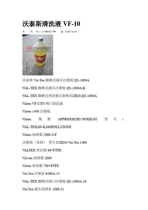
沃泰斯清洗液VF-10联系:郑-工15 260 822 709 Q 72 827 45 85沃泰斯Val-Tex脚踏式液压注脂枪QS-1800AV AL-TEX脚踏式液压注脂枪QS-1800A-KV AL-TEX脚踏式密封脂注脂枪CZH20-QS-1800AValtex VF-CTN阀门清洗液Valtex 1400注脂枪Valtex规格APPROX&LBS/363KILOS 型号:V AL-TEX(80-K)OOFOLLSTONEValtex润滑脂2000-S-P注脂枪(美国)型号:CZH20-Val-Tex 1400V ALTEX密封脂80+FTFEVal-tex润滑脂2000Valtex密封脂700+FTFEVal-Tex注脂泵6268A-13V AL-TEX脚踏式阀门注脂枪QS-1800A-10Val-Tex液压润滑泵1000-31Val-Tex注脂枪1000-31Val-Tex 液压润滑泵QS-2200AVal-Tex液压润滑泵QS-5000-CVal-Tex注脂枪QS-5000-CVal-Tex脚踏式液压注脂枪QS-5000 Valtex注脂枪VF-GALVal-Tex注脂枪GC-250Val-Tex GC-250Val-Tex 6268A-13Val-Tex 〝Quick Stick〞QS-2000A沃泰斯Val-Tex 液压润滑泵QS-2200A沃泰斯Val-Tex GC-250沃泰斯Val-Tex 6268A-13沃泰斯Val-Tex 〝Quick Stick〞QS-2000A 沃泰斯Val-Tex QS-2200A沃泰斯Val-Tex 〝Quick Stick〞QS-5000 沃泰斯Val-Tex QS-5000C“L’il Greaser”-MODEL 5-70“Easy Lube”-MODEL 10-70“Easy Lube”-MODEL 40-70Valtex 450Valtex 202Valtex 302Valtex PL1000Valtex VF-GALValtex VF-10Valtex VF-40Valtex VF-120Valtex VF-140V AL-TEX 6268A-13用于注入阀门清洗液和所有类型的润滑密封脂,对于各种黏度的物料都可以顺利注入阀门。
麦顿fd2 flexdraper

56 | MacDon FD2 FlexDraper®
SPECIFICATIONS | 57
2 pairs of coil springs, independent adjustment, transport lock-out / 178 mm (7”) / 4.8 degrees
FD2 FLEX RANGE
Standard (Factory) Range
Increased Range**
2000 mm (78.7”) width Hydraulic drive (reversible), self tracking rubber coated polyester fabric feed draper with rubber slats 107-122 m/min (350-400 ft/min), varies with combine brand
Reel: Type / Drive / Speed / Fingers
Pick-up reel, five bats, two-piece (double) or three-piece (triple), flip-over design, cam-leading finger control / Hydraulic / 0 to 67 rpm (varies depending on combine model) / 279 mm (11”) length, wear-resistant HD plastic, 102 mm (4”) spacing
*Product size availability varies by market. **All listed weights are approximations and will vary depending on options installed. Check with your dealer for combine ratings. Weight includes FM200 Float Module. The FM200 Float Module weighs approximately 1029kg (2270 lb); this number varies by combine model
电子秤标定方法大全

霸王超人大和————01 超众华德赛多利斯————114 福日和田衡之宝———06 众和精衡——————115 衡臣—————————17 昌帛磅志瑜大河—————116 衡天衡协衡新、衡志福—20 宏马中银大华——————117 桦利泰永州华德———32 珠江凯丰恒天——————118 天星仙华精衡————32 新永州明辉三峰—————123 威灵白云山双杰———32 科迪泰德西特天平————123 金利金菊联贸————34 优越惠而邦规矩—————124 梅特勒托利多—————37 爱华台湾JADEVERA———126 寺冈天合香海————39 昌信巨林亚太——————129 旭日耀华英展————65 三兴东松————————127 大阳、枝花、永杰———90 日本实用衡器钰恒————130 友声永州众和————91 中银正人大河——————132 长青冠衡新和基———97 湘平世伟——————133 奥特征龙三生————97 大华五强————————133 中侨天河上准———102 三积分燕影———————133 英菲中字牌————105 三峰风华————————134 中兴企鹅白云山——107 四方华泰超超——————134 中庆达中字耐克斯—109 直林顶尖百利达—————136 东松惠邦奋进———129 台湾腾龙———————139 霸王计价秤霸王电子秤标定霸王/大红鹰/永杰/万宝/风华计价秤霸王计价秤标定(1): 储存—9.845—储存—放砝码—储存—输入砝码重量—储存—输入重秤量—储存.霸王计价秤标定(2): 先短路,储存—0.567—储存—放砝码—储存—输入砝码重量—储存—输入重秤量—储存. 霸王计价秤标定(三分厂): 储存—6.911—储存—放砝码—储存—-输入砝码重量—储存—输入重秤量—储存.1.?? 霸王计价秤标定(1): 储存---9.845---储存---放砝码---储存---输入砝码重量---储存---输入重秤量—储存.222.?? 霸王计价秤标定(2): 先短路,储存---0.567---储存---放砝码---储存---输入砝码重量---储存---输入重秤量---储存. 3.?? 霸王计价秤标定(三分厂): 储存---6.911---储存---放砝码---储存----输入砝码重量---储存---输入重秤量---储存. 4.?? 威灵计价电子秤标定说明: 按*---9.845---*-----放砝码----*----输入砝码重量----*---输入重秤量---?5.霸王衡器ACS计价秤24键(14键按[去皮][清除])步骤操作说明总重窗口单价窗口总价窗口1 开机归零短接标定头[?? 0.00] [? 0.00] [? 0.00]2 按[储存][0·567][储存] [?? 0.00] [UNLOAD] [? 0.00]3 按[储存] 空秤[?????? ] [ load ] [?????? ]4 加码5kg按[储存] [?? **? ] [ Ld-in ] [????? 0]5 按[5·00]按[储存] [ 5·000 ] [ CAPP ] [-------]6 按[15000]按[储存] 输入最大量程[?????? ] [Ld-in ] [ 15000 ]7 [ 5。
电动液压注脂泵沃泰斯安全操作及保养规程

电动液压注脂泵沃泰斯安全操作及保养规程1. 引言电动液压注脂泵是一种常用于工业生产中的设备,主要用于给机械设备进行润滑。
为了确保注脂泵的正常运行,保证工作安全,延长设备寿命,我们需要遵循一定的操作规程和保养要求。
本文将重点介绍电动液压注脂泵沃泰斯的安全操作及保养规程。
2. 安全操作规程2.1 个人安全防护在操作电动液压注脂泵之前,必须确保已佩戴正确的个人防护设备,包括安全帽、安全鞋、防护手套和护目镜。
这些防护设备能够有效地保护操作人员的身体和面部,防止意外事故的发生。
2.2 设备准备在操作电动液压注脂泵之前,需要确保设备已经进行了正确的安装和调试。
检查电源电压和电流是否符合要求,并确保注脂泵的各个部件安装牢固且良好接地。
此外,还需要检查注油管路是否连接紧固,防止漏油。
2.3 开机前检查在启动电动液压注脂泵之前,需要进行一系列的检查工作。
首先,检查注脂泵的油位是否在正常范围内,如果低于最低标记线,应及时添加润滑油。
其次,检查电源线路是否正常,连接是否稳定可靠。
2.4 启动操作启动电动液压注脂泵时,需要确保周围环境安全。
按下启动开关,观察注脂泵运行是否正常,如有异常情况应立即停机检查。
同时,在操作过程中要保持设备周围的工作区域干净整洁,避免杂物堆积影响操作。
2.5 注意事项在操作电动液压注脂泵时,需要特别注意以下事项:•禁止超负荷运行,避免设备损坏或事故发生;•不得随意拆卸或改动注脂泵的机械部件,以免影响正常工作;•禁止将手指或其他物体伸入注脂泵的运动部件中,避免伤害;•禁止在运行中触摸泵体,避免烫伤;•定期检查注脂泵的运行情况,如发现异常应及时维修或更换故障部件。
3. 保养规程3.1 检查润滑油电动液压注脂泵的正常运行需要足够的润滑油。
定期检查注脂泵的油位,并根据需要补充润滑油。
同时,要定期更换注脂泵的润滑油,保证油润滑性能的稳定。
3.2 清洁维护保持电动液压注脂泵的清洁,可以延长设备的使用寿命。
Nordstrom注脂枪
Nordstrom扳手8888 M719+
Nordstrom旋塞阀B142/ 200CWP 1 1/4"
Nordstrom燃气旋塞阀手柄30546 15110 M9
专卖诺思卓姆Nordstrom管道注脂枪400-D
专卖诺思卓姆Nordstrom管道注脂机Hypregun-Plus 5Q
专卖诺思卓姆Nordstrom密封脂555
IEC滑环TBNP-6-8-LED-LED
TIDELAND莫尔斯TRB-400
Nordstrom 555通用型气动泵阀门注入密封脂,订货号:56290009,4.7L/罐
Nordstrom 555通用型气动泵阀门注入密封脂,订货号:56290009,5Qt/桶
Nordstrom密封脂735-D
Nordstrom密封脂731-D
Nordstrom注脂枪400-D专用密封脂735-J
Nordstrom注脂枪400-D专用密封脂731-J
Nordstrom注脂枪阀门密封Hypregun-Plus 5Q
Nordstrom扳手C-3001157
Nordstrom扳手C-3001157 SN-2
Nordstrom注脂枪400-D
Nordstrom注脂枪400-B
Nordstrom注脂枪400-A
Nordstrom注脂枪 Hypregun-Plus 5Q
Nordstrom注脂枪 Hypregun-Plus 5G
Nordstrom润滑脂950
Nordstrom阀门密封脂x-184
Nordstrom密封脂x-195
Nordstrom密封脂x-196rs
A-T Controls F83系列火安全三件套球值说明书

SERIES F83 3-Piece FiresafeThe F83 Series Firesafe 3-piece ball valves are the finest quality 3-piece valves on the market. The high quality investment castings feature a fully machined bore. The superior live-loaded packing system is accomplished with Belleville washers, Grafoil packing and a unique primary pyramidal stem seal. This advanced sealing system provides protection against stem leaks experienced by ordinary ball valves.Easy to Automate!See automated data sheets for pre-sized assembliesPneumaticElectricRTFE seats are standard, but various options are available for seat materials. The 50/50 STFE seat option is excellent for services that call for higher temperatures and more difficult applications including steam. Call us for details.C E R T I F I E DHigh Performance, Full Port 3-Piece Ball ValveISO 5211 Mounting Pad Class 400 to 600960 to 1480 psi (by size)1/4” to 2”* 1/4” THRU 2” QTY = 4 PCS* 2-1/2” QTY = 6 PCSHigh Performance, Full Port 3-Piece Ball ValveISO 5211 Mounting Pad Classes up to 600 1500 - 2000 psi (by size)SIZED FOR60 psi AIR SUPPL YSIZE MODEL1/4"F83-TX-025/TR1D-XX 3/8"F83-TX-038/TR1D-XX 1/2"F83-TX-050/TR1D-XX 3/4"F83-TX-075/2R2D-XX 1"F83-TX-100/2R2D-XX 1-1/4"F83-TX-125/2R2D-XX 1-1/2"F83-TX-150/2R3D-XX 2"F83-TX-200/2R4D-XXStem & Stem SealAPI 607 - 6th EditionC E R T I F I E DFiresafe tested to API-607(valve only)SERIES F8 3 3-Piece FiresafeDIMENSIONS (IN)VALVE SIZE A B C D E1/4" 5.98 2.760.79 2.65 2.583/8" 5.98 2.760.79 2.65 2.581/2" 5.98 2.760.79 2.65 2.583/4"7.95 3.430.79 2.65 3.291"7.95 3.430.79 2.78 3.291-1/4"7.95 3.430.79 2.90 3.291-1/2"9.29 4.490.79 3.13 4.412"9.29 4.490.79 3.42 4.41 DIMENSIONS SHOWN ARE FOR ASSEMBLIES SIZED FOR 80 PSI SUPPLYDESCRIPTION PART NO.SUFFIXDIMENSIONS (IN)VALVE SIZEABCDE1/4"7.95 3.430.79 2.65 3.293/8"7.95 3.430.79 2.65 3.291/2"7.95 3.430.79 2.65 3.293/4"7.95 3.430.79 2.62 3.291"9.29 4.490.79 2.78 4.411-1/4"9.29 4.490.79 2.90 4.411-1/2"9.294.490.79 3.13 4.412"10.87 4.880.79 3.42 4.82DIMENSIONS SHOWN ARE FOR ASSEMBLIES SIZED FOR 80 PSI SUPPLYDESCRIPTIONPART NO.SUFFIXAPI 607 - 6th EditionC E R T I F I E DFiresafe tested to API-607(valve only)SIZED FOR 60 psi AIR SUPPL YSIZEMODEL1/4"F83-TX-025/2R2S-XX 3/8"F83-TX-038/2R2S-XX 1/2"F83-TX-050/2R2S-XX 3/4"F83-TX-075/2R3S-XX 1"F83-TX-100/2R3S-XX 1-1/4"F83-TX-125/2R3S-XX 1-1/2"F83-TX-150/2R4S-XX 2"F83-TX-200/2R4S-XXSERIES F 83 3-Piece FiresafeBelleville Washer Stem & Stem SealSee valve part number matrixfor complete part number andoptions.NOTE: Heater and thermostat standard(2) auxiliary switches standardAPI 607 - 6th EditionC E R T I F I E D(valve only)F83C-TH-0200-XXX-X-_ _SAMPLE PART #(2) Valve Series(1) Prefix(4) End Connection(6) Seat, Lining & TrimMaterial(5) Valve Size(7) Special Designation(8) AdditionalSpecials(9,10,11) Options(3) Body/Ball/StemMaterialF83C-TH-0200-XXX-X-_ _SAMPLE PART #(2) Valve Series(1) Prefix(4) End Connection(6) Seat, Lining & TrimMaterial(5) Valve Size(7) Special Designation(8) AdditionalSpecials(9,10,11) OptionsMANUAL VALVE(3) Body/Ball/StemMaterialHOW TO ORDER:Manual Valves w/ OptionsHOW TO ORDER:Automated ValvesSAMPLE PART #(2) Valve Series(3) Body/Ball/StemMaterial(6) Valve Size(5) Seat, Lining, & TrimMaterial(4) End Connection (7) TRIAC Actuator Series(7) Actuator Size (7) Double Acting(8) Accessory F83C-TX-100/2R3D-XX-_TFM™ is a trademark of Dyneon™, a 3M Company.(1) Prefix。
QS-1800A脚踩注脂机操作规程
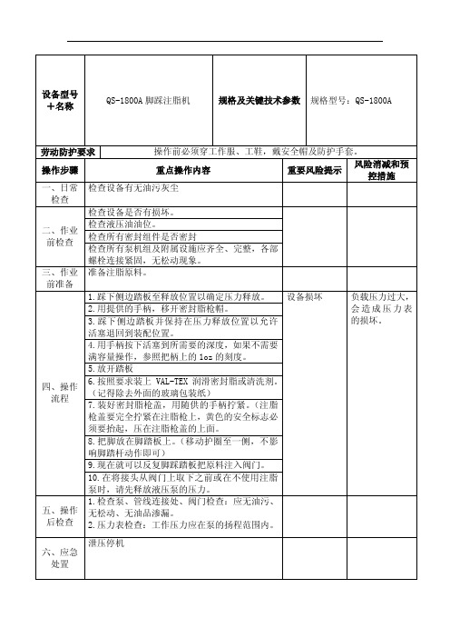
5.放ቤተ መጻሕፍቲ ባይዱ踏板
四、操作 流程
6.按照要求装上 VAL-TEX 润滑密封脂或清洗剂。 (记得除去外面的玻璃包装纸) 7.装好密封脂枪盖,用随供的手柄拧紧。(注脂
枪盖要完全拧紧在注脂枪上,黄色的安全标志必
须要抬起,压在注脂枪盖的上面。
8.把脚放在脚踏板上。(移动护圈至一侧,不影
响脚踏杆动作即可)
9.现在就可以反复脚踩踏板把原料注入阀门。
10.在将接头从阀门上取下之前或在不使用注脂
泵时,请先释放液压泵的压力。
1.检查泵、管线连接处、阀门检查:应无油污、 五、操作 无松动、无油品渗漏。 后检查 2.压力表检查:工作压力应在泵的扬程范围内。
泄压停机 六、应急
处置
七、日常 维护保养
八、其它
1.检查注脂机连接部位、密封件,应无松动、渗 漏现象。 2.检查注脂机所有阀门和仪表,均应正常可靠运 行。 3.检查注脂机液压油位应在正常范围内。 4.清除注脂机的灰尘和油污。 5.检查注脂机。 /
设备型号 +名称
QS-1800A 脚踩注脂机
规格及关键技术参数 规格型号:QS-1800A
劳动防护要求
操作前必须穿工作服、工鞋,戴安全帽及防护手套。
操作步骤
重点操作内容
重要风险提示
风险消减和预 控措施
一、日常 检查设备有无油污灰尘
检查
检查设备是否有损坏。
二、作业 前检查
检查液压油油位。 检查所有密封组件是否密封 检查所有泵机组及附属设施应齐全、完整,各部
螺栓连接紧固,无松动现象。
三、作业 准备注脂原料。
前准备
1.踩下侧边踏板至释放位置以确定压力释放。 设备损坏
负载压力过大,
注脂机、注脂枪操作手册

气动注脂机(型号ACTIV-8)ACTIV-8气动注脂机操作和保养规程一、ACTIV-8气动注脂机操作规程1.使用前将注脂机用抹布擦干净,检查注脂机上面的每个零部件是否有松动,如有松动则紧固松动的部件。
检查注脂机外观是否有污物,如果有则用带有汽油的毛巾或抹布将注脂机擦拭干净,特别注意注脂接头的清洁。
(如果注脂接头粘有沙子或比较坚硬的物体,则有可能沙子或坚硬的物体会随着润滑脂或密封脂从注脂嘴进入阀门密封系统。
如果活动阀门,就很有可能将阀门的密封面滑伤,使阀门密封系统失效。
2.将注脂机拖或拉到注脂现场,把塑料气管连接到注脂机下部气泵右侧的金属接头上。
3.将塑料气管的另一头连接到压缩机的金属接头上,然后将空压机接上电源。
4.用注脂机右侧的操作手柄将注脂机下部液压千斤顶的泄压丝堵拧松(将操作手柄插在泄压丝堵上逆时针旋转1/4-1/2圈即可),将注脂机托盘下部的支撑杆移出,用手缓慢往下压托盘至最下端即跟千斤顶接触,或者把气管接在注脂管泄压口利用空压机中的气压将其吹下。
然后取下托盘上的金属固定套筒,将套筒上的螺母拧下来,把10磅装的润滑脂或密封脂装入金属套筒里,然后将套筒上的螺母重新安装上并拧紧后放在托盘上。
5.用操作手柄将千斤顶下部的泄压丝堵拧紧,然后将手柄插入千斤顶上部的套筒里,上下操作手柄。
等装有润滑脂或密封脂的金属筒顶部接触到注脂机上的密封圈后,旋开密封圈上部的放空阀,继续上下操作手柄,等到有脂从放空阀均匀益处时关闭放空阀。
6.将注脂机气泵左侧的操作板踩下,继续上下操作手柄,注意观察小压力表的数值,等到压力上升至600-800kpa时停止操作手柄。
7.将注脂机上的注脂接头连接到阀门的注脂嘴上,用脚缓慢踩下注脂机气泵上面右侧的操作板,即开始注脂,注意观察注脂时的压力变化,注脂压力不要超过6000psi。
8.等听到注脂声音有明显变化且看到注脂压力立即下降时,表示一次注脂完成,注脂量大约为16盎司。
注脂时间大约需要1分钟。
VAL-TEX沃泰斯
V AL-TEXTEL-0595-2876-7952成立于1962年的V ALTEX公司现已成为行业首选的优质阀门养护产品的生产厂家。
已被多家著名阀门厂家指定为专用阀门养护产品供应商,如:美国卡麦隆阀门公司(Cameron),意大利格罗夫阀门公司(Grove隶属Dresser)等。
V AL-TEX产品主要在陕京管线,西气东输,四川石油管理局,中海石油管道公司,中石化管道公司等应用。
随着中国经济的高速增长,以及能源的开发,V AL-TEX公司更加重视中国市场的巨大潜力,并将长期致力于为中国用户提供一流的产品和服务,我们会竭诚做好产品供应及该产品的开发才刚刚起步,在国内外都还有很大的发展前景,天然气管线,阀门清洗、密封脂、注脂枪使需求量大。
1400(液压注脂枪)和附件适用润滑封脂:J、P 、CT12 重量:16磅/7.26千克1000—31(手动注脂枪)6268A-13(手动注脂枪)QS—2000A(气动/液压注脂泵)QS—2200A(电动/液压注脂泵)阀门清洗液型号描述重量推荐注脂设备磅千克VF-CTN 4×2磅/瓶8 3.63 1400、QS-2000A、1000-31 6268A-13、MM、QS-2200AVF-GAL 1加仑壶8 3.63 QS-5000、QS-5000-CVF-10 5夸脱罐装 10 4.53 5-70、10-70VF-40 5加仑提桶 40 18.14 40-70VF-120 16加仑桶 120 54.43 按要求VF-440 55加仑桶 440 199.58 按要求在使用Val-Tel (沃泰斯)润滑密封脂前要先对阀门进行清洗VAL-TEX阀门注脂枪 Nordstrom注脂枪Nordstrom Hypregun-Plus 5QDELTA注脂枪1699-09DELTA光栅V3-JC-S/R430HTA DC24V DELTA活套扫描仪TS2236 DC24VSEALWELD超级气动注脂机Gsgun-cSOFT GRADE密封脂Serck audco斯克奥德克密封脂(733 sealant)733清洗液:Val-tex VF-CTN润滑脂:Val-tex 2000密封脂:Val-tex 80+FTFEVAL-TEX沃泰斯700-S-10VAL-TEX脚踏式液压注脂枪CZH20-QS-1800A Val-tex电动注脂枪QS-2200AVAL-TEX气动注脂枪QS2000-AVAL-TEX 2000-S-10VAL-TEX密封脂80-H-JVAL-TEX 密封脂VF-40VAL-TEX注脂枪CZH20-Val-Tex 1400Val-Tex阀杆和螺纹润滑油10-SVal-Tex螺纹养护剂19-S超级气动注脂机G-A8GUN-C超级气动注脂机(含填装器)G-SGUN-C 超级气动注脂机(含填装器)G-UGUN-C 注脂枪型号1000-316268A-13"Quick Stick" QS-2000AQS-2200A“Quick Stick” QS-5000QS-5000-C“L’il Greaser” - Model 5-70 “Easy Lube” - Model 10-70 “Easy Lube” - Model 40-70 VAL-TEX通风帽CF-14-GBVal-Tex安全密封件SS-14Val-Tex压力释放工具PRT-12Val-Tex润滑适配器CIW-GB-1Val-Tex辅助配件AF-1Val-Tex包装器PI-14VAL-Tex 972 润滑脂VAL-Tex 80-HM 润滑脂VAL-Tex 700和750润滑脂PL-1000 闸阀润滑剂。
注脂枪执行标准(一)
注脂枪执行标准(一)注脂枪执行标准引言•注脂枪是一种常用于工业领域的工具,用于向机械设备中注入润滑剂。
•为了确保注脂枪的正常使用和操作安全,制定本文档旨在明确注脂枪执行标准。
注脂枪的定义•注脂枪是一种手持式或固定式装置,用于将润滑剂喷射至机械设备的摩擦表面,以减少摩擦和磨损。
注脂枪的分类1.手动注脂枪–通过手柄手动加压来推动润滑剂进入设备。
–应注意手动加压力度,避免因过量加压导致设备受损。
2.气动注脂枪–通过空气压力来推动润滑剂进入设备。
–气动注脂枪应配备调节阀,用于控制注脂的速度和压力。
注脂枪的使用要求•操作人员需经过专业的培训,理解注脂枪操作的基本知识和安全规范。
1.安全操作–在使用前,检查注脂枪是否完好无损,并确认其工作状态正常。
–使用时,注脂枪应与设备密封良好,避免润滑剂外泄或飞溅。
2.选择正确润滑剂–根据设备制造商的建议,选择适合的润滑剂。
–确保润滑剂的质量符合执行标准,并注意不要混用不同类型的润滑剂。
3.定期维护–对注脂枪进行定期的检查和维护,确保其正常工作状态。
–清洁和更换润滑剂时,应遵循制造商的说明。
注脂枪的维护与保养1.清洁–使用后,应清洁注脂枪的外部表面,并确保无残留物。
–清洁时,应注意避免水或其他溶剂进入注脂枪内部。
2.润滑–定期润滑注脂枪的各移动部件,以确保其灵活性和正常工作状态。
3.检查–定期检查注脂枪的连接部件和密封件,如有损坏或磨损应及时更换。
–检查注脂枪的压力表、压力调节阀等部件,确保其准确度和可靠性。
结论•注脂枪的使用和维护对于设备的正常运行和寿命具有重要意义。
•严格遵守注脂枪执行标准,能够保证操作的安全性和效果的可靠性。
请在使用前仔细阅读操作手册,并遵循执行标准进行操作和维护。
Cutler-Hammer固态DC注射刹车切断器安装与运行说明书

FOR YOUR SAFETYOnly qualified personnel should install this equipment, after first reading and understanding all the information in this manual. All instructions should be strictly adhered to. The user should consult Cutler-Hammer or a representitive for clarification of the contents of this manual should any doubt or questions arise.The installation of this equipment must be conducted in accordance with all national, regional and local electrical codes.All drawings and technical representations included in this manual are for typical installations and should not in any way be considered for specific applications or modifications. Consult Cutler-Hammer for supplemental instructions.Cutler-Hammer Canada accepts no liability for any consequences resulting from inappropriate, negligent or incorrect installation, application or adjustment of this equipment.The contents of this manual are believed to be correct at the time of printing. In following with our commitment to the ongoing development and improvement of our products Cutler-Hammer reserves the right to change the specification of this product and/or the content of this instruction manual without notice....1 DESCRIPTION..............................................PAGE 1......1.1 OVERVIEW..........................................................PAGE 1......1.2 APPLICATION NOTES...............................................PAGE 2......1.3 CONTROLS..........................................................PAGE 31.3.1 CA398-3 LOGIC........................................................PAGE 3......1.3.2 CA398-3 REGULATION...............................................PAGE 3.........2 SPECIFICATIONS..........................................PAGE 52.1 POWER RATING.....................................................PAGE 5............2.2 CURRENT AND FUSE RATING......................................PAGE 52.2.1 NOTES.................................................................PAGE 5......2.3 SERVICE CONDITIONS..............................................PAGE 6............2.4 DIMENSIONS........................................................PAGE 6......2.5 SCR INSTALLATION SPECIFICATIONS.............................PAGE 72.5.1 SCR TIGHTENING PROCEDURE.....................................PAGE 7.........3 CARD FUNCTIONS.........................................PAGE 9......3.1 CARD LAYOUT......................................................PAGE 9......3.2 LED AND NEON INDICATIONS......................................PAGE 9....3.3 ADJUSTMENTS......................................................PAGE 103.3.1 POTENTIOMETERS...................................................PAGE 10....3.3.2 LINK SELECTION.....................................................PAGE 10....3.3.3 PUSHBUTTON.........................................................PAGE 10........3.4 TERMINALS.........................................................PAGE 113.4.1 CUSTOMER TERMINALS.............................................PAGE 11....3.4.2 TERMINALS FOR INTERNAL USE...................................PAGE 11........3.5 FAULTS..............................................................PAGE 123.5.1 PHASE LOSS...........................................................PAGE 12....3.5.2 INSTANTANEOUS OVER CURRENT (IOC)..........................PAGE 12....4 INSTALLATION AND START UP.............................PAGE 13..4.1 INSPECTION........................................................PAGE 13....4.2 SAFETY PRECAUTIONS.............................................PAGE 13....4.3 MOUNTING GUIDELINES............................................PAGE 13....4.4 WIRING GUIDELINES...............................................PAGE 14....4.5 START UP...........................................................PAGE 14....4.5.1 CHECKS BEFORE POWER-UP........................................PAGE 14....4.5.2 WITH POWER ON.....................................................PAGE 15....5 TYPICAL CONNECTIONS...................................PAGE 17..5.1 STAND ALONE DC INJECTION UNIT WITH ZERO SPEED DISABLE PAGE 17....5.2 TRU-START STARTER WITH DC INJECTION.......................PAGE 18....5.3 REVERSING TRU-START STARTER WITH DC INJECTION, 125 AMPSAND BELOW.............................................................PAGE 19..5.4 REVERSING TRU-START STARTER WITH DC INJECTION, 200 AMPSAND ABOVE..........................................................PAGE 20....6 SPARE PARTS.............................................PAGE 21..1DESCRIPTION1.1OVERVIEWThe TRU-START DC Injection braking units provide smooth braking for AC induction motor. The brake units offer adjustable braking because they are current controlled. Unlike a mechanical brake, an electrical brake will never wear out. The brake operates by injecting DC current in two phases of the motor to rapidly decelerate it to zero speed.These units can be supplied as an option to the TRU-START solid state starter, or as stand alone units for new or retrofit installations.Cutler-Hammer TRU-START DC Injection braking modules offer a unique combination of features that make it very reliable, easy to use, and energy efficient. These features include: Closed Loop Current Regulation:The brake, operating with a closed loop current regulator, provides consistent torqueevery time. This torque is independent of line voltage variations.Direct Power Connection:The brake's power input is connected directly to the AC line, and the power output isconnected directly to the motor, no contactors are required. The unit adapts itself toany input voltage between 200 and 600 VAC with no adjustments required.Efficient Power Circuit:The power circuit is an efficient four Silicon Controlled Rectifier ( SCR )configuration which uses some of the SCR's as a "free wheeling diode", thusmaximizing the DC current through the motor coils generated by the AC inputcurrent.With every benefit there is usually a trade-off. Although the TRU-START DC Injection brake unit will neverwear out like a mechanical brake, the trade-off is that should there be a loss of power, the brake unit will not operate without battery back-up. Cutler-Hamer can supply a reliable battery back-up to overcome this disadvantage.Braking is initiated when the motor starter is opened and the voltage across the motor has dropped to below 30% or 80% of the line supply. DC injection is removed after an adjustable period has elapsed. It does not provide zero speed sensing, although a normally closed contact from a zero speed switch may be connected to the Disable Input.If braking is released before the motor stops, the motor will coast to rest. If the braking remains on after the motor stops, the DC supply will provide a holding brake.1.2APPLICATION NOTESThe motor torque/speed characteristic of an induction motor under DC supply is similar to the normal curve published for constant frequency, at 50 or 60 Hz, but this time having "synchronous speed" zero RPM. This is illustrated below.For smooth braking the DC current is typically adjusted to 300% of the motor nameplate current. The stopping time depends on the torque setting and also the inertia of the mechanical system.Electric braking is not recommended for continuous or repetitive operation. The kinetic energy of the mechanical system is transformed into heat during braking ( energy conservation ). That heat is dissipated in the rotor of the motor.On wound rotor motors the external rotor resistance will absorb most of the energy. On squirrel cage motors, overheating of the motor is a real danger if frequent operation is used.Keeping DC current on the motor stator for a short time after the motor has stopped is quite acceptable. The heat produced by the I2R losses are not significant, and they are dissipated in the stator only, not in the rotor where the rotational energy is dissipated.1.3CONTROLSThe OP-STOP unit contains two major parts, the power circuit and the control card.The power circuit is a 4 SCR single phase full wave controlled rectifier. This configuration optimizes the DC current injected to the motor per input current.The control is contained in a single PC board, CA398-3. This board is common to all Cutler-Hammer DC Injection models.1.3.1CA398-3 LOGICDC injection will be applied to the motor when two conditions are met. The starter isopened and the motor terminal voltage has decayed to 30% or 80%, jumper dependent,of the line voltage. The starter can not be energized for a period of 1-2 seconds afterthe DC injection cycle.This design has the significant advantage that the braking module will remain off in thecase of having an open auxiliary contact from either a broken wire or faulty contact.The braking action can be externally defeated at any time by applying 115 VAC to theDisable Input.The braking action is inhibited when an instantaneous over current is detected. TheIOC fault is detected and latched until the Reset switch is pressed. A form C relaycontact is available to interlock the brake unit from the motor starter. The startercannot be energized while DC current is being applied to the motor or during a faultcondition.1.3.2CA398-3 REGULATIONThe brake module operates in current control at all times. The current is adjusted via aninternal potentiometer and the current feedback signal is generated by a currenttransformer mounted on the AC line. A unique circuitry reconstructs the free wheelingcurrent in the DC output for accurate current regulation.The output of the current regulator is used in a comparator circuit that performs thephase control on two SCR's. The other two SCR's are fully phased on to provide freewheeling action, minimizing the ripple current.Two opto-couplers are used to generate the line synchronization signal. Each optooutput is used to generate a ramp that is used in the comparator with the currentregulator output.The motor voltage feedback is used to sense voltage levels for proper sequencing andnot to perform any regulation.2SPECIFICATIONS2.1POWER RATINGPOWER200-600VAC, 50/60 HzCONTROL115 VAC@50 Hz or 120 VAC@60 Hz, 10VARATING Intermitent duty, See Section 2.2300% for 30 seconds, once every 30 minutesAll models have 1600V PIV SCR'sCONTACTS DC injection relay contacts rated at 1A, 120VACPROTECTION Short circuit by HRC fuses or circuit breaker(supplied upon request)Voltage surge protection by snubber's and MOV's across the SCR's2.2CURRENT AND FUSE RATINGCURRENT RATINGDCI MODEL AMPS MOTORHP @ 575 VMOTORHP @ 460VFUSEAMPSSCRTYPETRU-020-DCI 20201520ModuleTRU-040-DCI 40 403040ModuleTRU-080-DCI 75 756080ModuleTRU-125-DCI 125125100125 ModuleTRU-200-DCI 200200150200DiscTRU-300-DCI 300300250300DiscTRU-500-DCI 500500400500Disc2.2.1NOTES2.2.1.1The HP listing is for reference only. For proper selection use the current rating.2.2.1.2The fuses recommended are Class J time-delay type. This fuse is beingsuggested even though it may not protect the SCR in an output shortedcondition while braking. It will protect the unit when starting to operate into ashorted output. In the case of a shorted SCR, the fuse is there to clear the faultonly.2.2.1.3The RMS AC line current is equal to : AC RMS = DC Amps x √ Duty CycleAssuming 10A motor, TRU-START DC Injection set at 300% current (30 A DC),free wheeling for 70% of the cycle, then the AC current is 16A.2.2.1.4All TRU-START DC Injection models are built without cooling fans because theyare short duty rated.2.3SERVICE CONDITIONSELEVATION For altitudes in excess of 2000 meters / 6600 feet above sea level,all assemblies must be derated 1% for every 100 meters / 330 feetaboveAMBIENT TEMPERATURE Do not install in areas where ambient temperature falls below 0°C / 32°F or exceeds 40°C / 104°F2.4DIMENSIONSDCI MODELHeight × Width × DepthCHASSIS NEMA 1 / NEMA 12TRU-020-DCI41cm × 22cm × 15cm41cm × 22cm × 18cm16" × 8.5" × 6"16" × 8.5" × 7"TRU-040-DCI 43cm × 27cm × 19cm43cm × 30cm × 27cm 17" × 10.5" × 7.5"17" × 12" × 10.5"TRU-080-DCI 43cm × 27cm × 22cm43cm × 30cm × 27cm 17" × 10.5" × 8"17" × 12" × 10.5"TRU-125-DCI 53cm × 27cm × 24cm53cm × 30cm × 27cm 21" × 10.5" × 8.5"21" × 12" × 10.5"TRU-200-DCI 28cm × 33cm × 27cm61cm × 61cm × 30cm 11" × 13" × 10.5"24" × 24" × 12"TRU-300-DCI 42cm × 37cm × 28cm76cm × 61cm × 30cm 16.5" × 14.5" × 11"30" × 24" × 12"TRU-500-DCI 45cm × 42cm × 36cm76cm × 61cm × 30cm 17.5" × 16.5" × 14"30" × 24" × 16"NOTE : For dimensions of TRU-START DC Injection units in conjunction with solid state C-H's starter, refer to the TRU-START manual reversing chassis dimensions.2.5 SCR INSTALLATION SPECIFICATIONS2.5.1SCR TIGHTENING PROCEDURE2.5.1.1Clean both heat sink and SCR surfaces.2.5.1.2Apply a thin layer of joint compound (Noalox) to both SCR surfaces.2.5.1.3Observe correct SCR polarity.2.5.1.4Install SCR so that roll pins engage dimples on both sides of the SCR.2.5.1.5Tighten clamp bolts evenly until finger-tight.2.5.1.6Tighten each bolt according to table below (based on number of spring bars andsize of bars).* Note : SMALL clamps are 4.25 inches / 10.5 cm and LARGE clamps are 5 inches /12.5 cm.CLAMP SIZE SPRING BARS BOLT TURNS PASTFINGER TIGHTSMALL10.8SMALL21LARGE3 1.8LARGE4 1.83CARD FUNCTIONS3.1CARD LAYOUT3.2LED AND NEON INDICATIONSLED NAME COLOUR DESCRIPTIONLD 1DC INJCT RED On when unit is brakingLD 2PWR GREEN Must be On when 115 VAC is appliedLD 3IOC RED Instantaneous Over-Current fault indicationwhen illuminatedNE1PHASE OK ORANGE Phase loss indication when neon not glowing3.3ADJUSTMENTS3.3.1POTENTIOMETERSPOT NAME RANGE DEFAULTSETTINGDESCRIPTIONRV1BRAKINGTIME 1-60 sec30%Adjust the braking timeCW rotation increases the timeRV2TORQUE100-300%50%Adjust DC currentCW increases the braking torque(current)3.3.2LINK SELECTIONLINK NAME POSITION DESCRIPTIONJP1VOLTAGELEVEL LO(Normal)Braking action starts when motor starter has openedand the motor terminal voltage has decreased to 30%of the line voltage.HI Braking action starts when motor starter has opened and the motor terminal voltage has decreased to 80%of the line voltage. See important notes below.HI setting is only used when the stopping time is critical and must be around 1-2 seconds. For this application 300% DC current is not adequate. Consult factory before using this jumper position.When the DC Injection unit is set on the HI level a current surge could occur due to the motor CEMF and the free wheeling action of the power circuit.3.3.3PUSHBUTTONPUSHBUTTON NAME DESCRIPTIONSW1RESET Reset IOC fault trip3.4TERMINALS3.4.1CUSTOMER TERMINALSTERMINAL NO.DESCRIPTIONJ2L1, N115 VAC control voltage input, L1 being hot and N, neutralL1 input is protected with internal fuse, 1A 250VAC J41, 2115 VAC supply for external interlock contacts3 A normally open contact from the motor starter auxiliary mustbe connected between this teminal and terminals 1 or 2 to sensewhen the starter is de-energized to enable braking actionWhen using a TRU-START starter in conjuction with the DCInjection, this terminal is to be jumpered to terminal 1 or 24When 115VAC from terminals 1 or 2 is applied to this input,braking is disabled5Common DCI relay contactThe Form-C relay is de-energized while braking and when afault exists6Normally open DCI relay auxiliary contact7Normally closed DCI relay auxiliary contactR71, 2Burden resistor terminals for calibration of DC injection currentSee table in Section 4.43.4.2TERMINALS FOR INTERNAL USETERMINAL NO.DESCRIPTIONJ124V, COM This terminal is used by C-H as a 24V input to providebattery back up for DC injection in case of power loss J31, 2CURRENT FBKFrom current transformer for motor current feedback J51, 2MOTOR VFBKFrom T1, T2 motor terminals for motor voltage feedback SCR1G1, K1Gate connection to SCR 1SCR2G2, K2Gate connection to SCR 2SCR3G3, K3Gate connection to SCR 3SCR4G4, K4Gate connection to SCR 4OPT1-20Provided for ribbon cable link to TRU-START starterThis provides signals from the TRU-START to the DCI thatindicate the run status of the starter, replacing the auxiliaryinput and prevents starting during DC injection or a fault3.5FAULTSWhen a fault exists the DC Injection DCI relay is de-energized, preventing a properly interlocked starter from being activated. When an TRU-START DC Injection is used in conjunction with a C-H starter, this interlock is also carried out through signals passed by energized the ribbon cable at OPT. When no faults exist and DC injection is not active, the DCI relay is energize. Therefore, if the 115 VAC supply is not present the "fail-safe" interlock will prevent the use of the starter. The faults are explained below.3.5.1PHASE LOSSIf the single phase power ( 200-600V ) to L1 and L2 terminals is not present, NE1 willbe off and the DCI relay de-energized. When this condition is corrected the unit willallow the starter to be energized.3.5.2INSTANTANEOUS OVER CURRENT (IOC)If the current feedback exceeds 1000% of the current setup by the burden resistor (Rb),the unit will trip on IOC and de-energize the DCI relay. LD2 will be illuminated toindicate an IOC fault and is reset via SW1, RESET. Causes of this fault may be ashorted output or simply a burden resistor sized too small. Refer to Section 4.4 forburden table.4INSTALLATION AND START UP4.1INSPECTIONThe DC Injection unit has been packaged to protect it from damage caused by normal handling during shipping, however mishandling may cause damage to the DC Injection unit.Unpack the unit as soon as it is received and check for any shipping or storage damages. If damage is found notify the carrier. Any damage claim must be filed by the customer since all shipments are F.O.B. Cutler-Hammer plant unless otherwise specified.If the DC Injection unit is not installed when received, store it in a clean, dry, well ventilated area, free from heat, humidity, oil, dust and metal particles.4.2SAFETY PRECAUTIONSgrounded properly. An incoming circuit breaker or disconnect switch must be locked open before wiring and servicing this electrical brake, motor, or other related equipment. This equipment must be installed and serviced only by qualified personnel, familiar with this unit.The user is responsible for ensuring that proper short circuit protection is provided by either a circuit breaker or HRC fuses.4.3MOUNTING GUIDELINESStandard Nema 1 DC Injection units must be installed indoors in a well ventilated area,free from heat, humidity, oil, dust and metal particles.One foot of clearance must be kept around the perimeter of the unit in a naturally cooled setup. The equipment must be mounted away from any heat source. See Section 2 for additional specifications and derating. Be aware that the heatsink may reach temperatures of 70°C / 158°F during normal operation. Do not install the unit in contact with any material that can not accept this temperature.The DC Injection Unit must be mounted vertically and where it will not experience excessive shock or vibration.4.4 WIRING GUIDELINESFollow all local electrical codes for installation requirements and wire sizing. Size the power wiring as per local code and on long wire runs it is recommended to use a larger wire size.Power factor correcting capacitors MUST NOT be connected to the DC Injection unit output.If desired, they must be connected on the line side of the unit. Capacitors can be connected before starting or preferably after the motor has reached full speed.For short-circuit fuse protection refer to the table in Section 2.4.5START UP4.5.1CHECKS BEFORE POWER-UP4.5.1.1Ensure that all electrical connections are completed as shown on schematics insection 6, and that connections are properly tightened. The most importantconnection is the interlock between the DC Injection unit and the starter.4.5.1.2Ensure that the burden resistor is equal or larger than the value listed in thefollowing table or calculated by the following equation :Rb = Effective Current Transformer Ratio ÷ Motor Nameplate Amps4.5.1.3Set JP1 link to LO.4.5.1.4Adjust RV2, braking torque, and RV1, braking time, to 50%.4.5.1.5Install a Disable switch between terminals 2 and 4 of J3 in the open position.Switch is to be closed once the motor has reached zero speed or if anyproblems occur during braking.4.5.1.6If a Disable switch is not used, then set RV2 to 30%, about 20 seconds orlower.WARNINGDO NOT OPEN LOAD SIDE DISCONNECTING DEVICE DURINGDC INJECTION CYCLE. FAILURE TO OBSERVE THIS WARNINGWILL RESULT IN DAMAGE TO THE DISCONNECTING DEVICEAND MAY CAUSE PERSONAL INJURY.MODEL MOTORAMPSBURDENRESISTOR (¼ W)EFFECTIVE CTRATIOTRU-015-P c/w DCI 1068 Ω750 : 11547 ΩTRU-020-DCIorTRU-030-P c/w DCI 2039 Ω750 : 1 3027 ΩTRU-040-DCI orTRU-050-P c/w DCI 4039 Ω1500 : 1 5033 ΩTRU-080-DCI or TRU-080P c/w DCI 6039 Ω2500 : 1 8033 ΩTRU-125-DCI orTRU-125-P c/w DCI 10027 Ω2500 : 1 12522 ΩTRU-200-DCI orTRU-200-P c/w DCI 15018 Ω2500 : 1 20012 ΩTRU-300-DCI orTRU-360-P c/w DCI 20027Ω5000 : 1 30018 ΩTRU-500-DCI orTRU-500-P c/w DCI 40022 Ω8500 : 1 50018 Ω4.5.2WITH POWER ON4.5.2.1Run the motor up to full speed and command the starter off. If the motorreaches zero speed from the DC injection cycle, close the switch to the DisableInput to disable the braking.4.5.2.2Re-adjust the braking torque pot, RV2, if the actual braking time has to beincreased or decreased to bring the motor to zero speed.4.5.2.3Once the braking torque is set, then adjust RV1 to match the DC injection timewith the actual stopping time of the motor. Typically, the injection should ceasewhen the motor is at zero speed or shortly after. LD1, DC INJCT is anindication of braking. Each 10% graduation in RV1 corresponds toapproximately 6 seconds.WARNINGALLOW TIME FOR THE MOTOR TO COOL BEFORE ANOTHERSTART / STOP SEQUENCE IS INITIATEDFREQUENT START / STOP COULD CAUSE MOTOR DAMAGEDUE TO OVERHEATING5TYPICAL CONNECTIONS5.1STAND ALONE DC INJECTION UNIT WITH ZERO SPEED DISABLE5.2TRU-START STARTER WITH DC INJECTION125 AMPS AND BELOW200 AMPS AND ABOVE6SPARE PARTSMODEL CTRATIOCTPART NO.SCRPART NO.SNUBBERCARDCONTROL CARDDESCRIPTIONTRU-020-DCI 1500:1T261123N10SP03CA524CA398-3 TRU-040-DCI 1500:1T261123N10SP06CA524CA398-3 TRU-080-DCI 2500:1T262230N10SP16CA524CA398-3 TRU-125-DCI 2500:1T262230N20SP06CA524CA398-3 TRU-200-DCI 2500:1T262230N728452CA232CA398-3 TRU-300-DCI 5000:1T265320N718602CA232CA398-3 TRU-500-DCI 8500:1T268320N718133CA232CA398-3Company Information1-800-498-2678, or visit www.cutler-hammer.ca .more than 50 countries. For more information visit .。
- 1、下载文档前请自行甄别文档内容的完整性,平台不提供额外的编辑、内容补充、找答案等附加服务。
- 2、"仅部分预览"的文档,不可在线预览部分如存在完整性等问题,可反馈申请退款(可完整预览的文档不适用该条件!)。
- 3、如文档侵犯您的权益,请联系客服反馈,我们会尽快为您处理(人工客服工作时间:9:00-18:30)。
沃泰斯脚踏式注脂枪QS-1800A-K
联系:郑-工15 260 822 709 Q 72 827 45 85
沃泰斯val-tex阀门润滑密封脂80-H-J
沃泰斯val-tex清洗剂VF-CTN
沃泰斯val-tex含硫化钼润滑剂2000-S-P
V AL-TEX QS-2200A 电池RB12V
Val-Tex阀门清洗液VF-CTN
Val-Tex密封脂80-H-J
Val-Tex脚踏式注脂枪QS-1800A-K
Val-tex液压润滑泵1400
Val-tex润滑脂2000-S-P
SEALWELD 超级手动注脂枪G-SGUN-C
SEALWELD 简易填装桶G-EZLOADER
SEALWELD 80 润滑脂S-EQ-10P 一桶(注:该型号是用于注脂机非注脂枪)
SEALWELD 80 润滑脂S-EQ-SGC 一箱
SEALWELD 注脂机G-A8GUN-C(配桶装的润滑脂)
SEALWELD润滑脂2000-S-CT12
SEALWELD 清洗剂VCPLUS
SEALWELD 清洗剂S-V AP-SGC
SEALWELD 密封脂5050#
SEALWELD 密封脂X5050#
SEALWELD 润滑剂911
DNH室外防爆扬声器DNH\HS-15 EEXMNT
DNH 防爆喇叭MODEL:DSP-25EEXMN(T)
DNH 喇叭BK-560T
DNH 扬声器型号为:HP-6CT/100V/500-7500HZ/6W
防水号角扬声器:DST-100/DH-50(最大功率100W)
DNH 扬声器DSP-15(T)
DST-100/DH-50(最大功率100W)
室外防爆扬声器HS-8EEXMNT
室外防爆扬声器DSP-15EEXMNT
室内扬声器HP-15T
挪威DNH水下扬声器AQUA-30
室外25W防爆扬声器型号:DSP-25EExmNT; 品牌:DNH
室内壁挂扬声器型号:SAFE-10P; 品牌:DNH
室内吸顶防水扬声器型号:HPS-6C; 品牌:DNH
DNH 喇叭BF-620T
DNH 喇叭HPS-6CT
DNH 喇叭BIVEP-6T
DNH 喇叭SAFE-10PT
DNH 喇叭H-60EExeNT
DNH 喇叭HS-8EExmNT
DNH 喇叭DSP-25EExmNT
DNH
室外防爆扬声器(15W)DNH-15EexmNT(防爆等级为IP56)
现场房间室内防爆扬声器(8W)DNH HS-8EexmNT(防爆等级为IP56 室内吸顶式扬声器(3W)HSP-1081
扬声器丝堵DNH专用
防爆接线盒一进两出
壁挂式扬声器(5W)SAFE-10PT
DNH DPS25EExmNT DNH HS-15EEmNT DNH SAFE-10P DNH HPS-6C
DNH H-60EEXMN(T)。
