DMF-5005N-COE-DDN, 规格书,Datasheet 资料
ipacs-5961-nw 母线成套保护装置 技术说明书

iPACS-5961-NW母线成套保护装置技术说明书符合南网标准化要求《南方电网220kV母线保护技术规范-Q/CSG-2011》及《南方电网10 kV~110 kV 元件保护技术规范-Q/CSG-2011》中母线保护相关要求江苏金智科技股份有限公司Wiscom System Co.,Ltd.iPACS-5961-NW母线成套保护装置技术说明书编制: 王勇博校核:王广领审定:高亮版本号: V1.03发布日期:2015年09月前言为了指导专业管理人员和整定人员,江苏金智科技股份有限公司研发部编写了《iPACS-5961-NW母线成套保护装置技术说明书》,本手册力求实用,涵盖了设备的技术条件、软硬件原理、逻辑框图、定值清单及整定说明等编写本手册的主要目的是为保护运维人员、整定人员、技术管理等人员提供一本实用工具书,当现场遇到疑问时能通过查找手册相关内容解决大部分的工程问题。
因时间紧迫且平时支持工作繁重,可能有些地方内容不够详尽或者存在错误,欢迎大家批评指正,我们将在今后继续完善,为工程的顺利实施及产品的安全、可靠运行提供技术保障。
最后,衷心感谢江苏金智科技股份有限公司工程服务部门在手册编制过程中给予帮助。
在手册编制过程中给予帮助。
目录前言 (3)目录 (4)第一章概述 (1)1.1手册内容介绍 (1)1.1.1整套手册说明 (1)1.1.2技术说明书说明 (1)1.2适用范围及主要功能配置 (2)第二章安全须知 (4)2.1安全标识符号 (4)2.2标识举例 (4)2.2.1警告标识 (4)2.2.2小心标识 (5)2.2.3注意标识 (5)2.2.4防静电标识 (5)2.2.5接地标识 (6)第三章装置介绍 (7)3.1概述 (7)3.1.1适用范围及主要功能配置 (7)3.1.2产品版本变更 (7)3.1.3产品主要特点 (7)3.1.4装置执行的标准 (8)3.2技术条件 (8)3.2.1环境条件 (8)3.2.2电气绝缘性能 (9)3.2.3机械性能 (9)3.2.4电磁兼容性 (9)3.2.5安全性能 (10)3.2.6热性能(过载能力) (10)3.2.7功率消耗 (10)3.2.8输出触点容量 (10)3.3装置主要技术参数 (11)3.3.1额定参数 (11)3.3.2交流回路精确工作范围 (11)3.3.3主要技术指标 (11)3.4订货须知 (12)第四章装置硬件 (13)4.1装置功能组件概述 (13)4.2装置硬件系统框图 (15)4.3装置插件说明 (15)4.3.1交流插件 (19)4.3.2 CPU插件 (19)4.3.3通讯插件(COM) (19)4.3.4开入插件(DIN) (19)4.3.5开出插件(DOUT) (20)4.3.6信号接点输出插件(SIG) (20)4.3.7电源插件(PWR) (20)4.3.8显示面板(LCD) (20)第五章装置软件及保护功能 (22)5.1母线差动保护 (22)5.1.1电流突变量启动元件 (22)5.1.2比率差动元件 (22)5.1.3电压闭锁元件 (23)5.1.4 CT饱和检测元件 (24)5.1.5故障母线选择逻辑 (24)5.1.6母联(分段)充电状态自动识别和闭锁差动 (25)5.1.7差动回路和出口回路的切换 (26)5.1.8母线各接线方式下的支路分配 (29)5.2母联(分段)死区保护 (30)5.3母联(分段)失灵保护 (31)5.4启动分段失灵和分段失灵保护 (31)5.5断路器失灵保护 (32)5.5.1断路器失灵电压闭锁元件 (32)5.5.2线路单元断路器失灵保护 (32)5.5.3主变单元断路器失灵保护 (33)5.6母联代路运行方式 (34)5.7母联(分段)过流保护 (34)5.8母联(分段)非全相保护 (34)5.9CT断线告警及闭锁 (35)5.10PT断线告警 (35)5.11母线运行方式识别及刀闸辅助接点异常时的处理 (36)5.12500K V站变压器低压侧母线主变变低断路器跳闸联跳母线功能 (36)第六章定值清单及整定计算说明 (39)6.1 I PACS-5961定值清单及整定计算说明 (39)6.1.1系统参数与整定说明 (39)6.1.2母线保护定值与整定说明 (41)6.1.3母联/分段保护定值与整定说明(选用功能) (43)6.1.4 500kV站低压母线变低跳闸联跳功能定值(选用功能) (45)6.1.5保护压板定值与整定说明 (45)6.1.6母线编号整定说明 (46)附录 (47)附录1:字符和中文字符集 (47)附录2:模拟盘I PACS-5963简介 (52)附录3:装置调试与运行 (53)附录4:I PAC-5961母线成套保护装置操作说明 (60)1.1面板布置图 (60)1.2 液晶显示说明 (61)1.3命令菜单使用说明 (62)第一章概述摘要:本章向用户介绍手册内容1.1 手册内容介绍1.1.1整套手册说明技术说明书设计安装手册测试检修手册运行操作手册一书三册所包含内容如下:●技术说明书:包含原理说明和整定要求的内容,如装置功能配置、原理说明、保护逻辑框图、定值清单、整定说明等●设计安装手册:保护装置设计、安装及相关检查的指导说明。
FORCE说明书2015

配电装置软导线拉力计算程序Force用户操作手册版本:20152015年3月南京1.编制依据Force软件的编制参考了《电力工程电气设计手册电气一次部分》(以下简称《手册》),第八章第四节“导线实用力学”部分的内容。
计算原理、计算方法与《手册》上相同,输入、输出格式也参考了《手册》第454页的例程序,并作了部分改进。
2.功能介绍Force软件可计算各电压等级配电装置中,以耐张绝缘子串悬挂的软导线,在各种环境状况下的水平张力、弧垂、风压等数据,并可依据计算结果填写相关表格。
因此,Force软件有计算及绘图两项功能。
2.1计算功能Force软件通过对原始数据文件(*.txt,且为ANSI编码格式)的分析、录入,分别计算出最高、最低温度、覆冰、大风、安装、上人检修各状态下的导线水平张力、支座反力、导线弧垂、最大风速时导线上的侧向风压,以及安装紧线时梁上的集中荷重等数据,并以简明易懂的格式形成输出文件(*.out)。
为便于验证计算结果的正确性,Force软件在完成计算后,还同时生成无冰无风、最大风速、三相导线上人检修、单相导线上人检修、导线安装、有冰有风6个状态下的M、D计算表,输出至另一个结果文件中(*.run)。
2.2绘图功能工程的施工图阶段,在绘制配电装置断面图时,为便于施工安装人员现场对导线放样,一般需绘制跨线或母线的安装曲线表,表中注明各种常见环境温度下导线的弧垂。
Force软件中的Curve.lsp程序,可读取*.txt及*.out 文件,在断面图上绘制安装曲线表。
电气专业向土建专业提供构架荷载资料时,一般会把配电装置中各档导线的计算结果:张力、支座反力、风压等数据,汇总整理在一张总表上提供,Force软件中的Fortz.lsp程序可读取*.out文件,快速而准确的实现此项功能。
3.原始数据文件格式及录入步骤Force软件的原始数据文件为纯文本格式,跟据引下线个数不同数据文件总行数分别为10行或11行。
sangfor ngaf m5150-f-i datasheet说明书
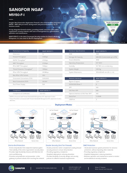
Performance & Capacity NGAF M5150-F-I DimensionIPSec VPN Throughput Max IPSec VPN Tunnels Concurrent Connections (TCP)New Connections (TCP)Dual Power Supply1U 250Mbps 3001,000,00025,000N/AHardware Specifications RAMStorage HD Capacity Power [Watt] Max Operating T emperature Humidity System Weight System DimensionsNGAF M5150-F-I 4GB64G SSD (Customizable up to 2TB)40W 0°C~40°C5%~95% non-condensing 3.85 Kg300x430x45 mm (W x L x H)Network Interfaces Bypass (Copper)10/100/1000 Base-T SFP10G Fiber SFPOptional Interface & 10G Fiber SFP*Serial Port USB PortNGAF M5150-F-I 1 pair 6N/A N/A N/A 1 x RJ452End-to-End Protection - End-to-end protection from endpoint to business system- T otal visibility of the entire organization security status- Provides High Availability features with Multi-line HA and Load Balancing- Proactive early detection and prevention at thegateway to prevent attacks from reaching the network Double Security (2nd-Tier Firewall)- Double protection which complement existing firewall security policies to ensure full protection - Providing regulatory compliance- Simplified deployment, reducing downtime - Provides flexibility of security design and security policies for di erent business requirementsDMZ Protection- Dedicated business system protection for advance protection, without impacting other networks - Providing regulatory compliance- Simplified deployment, reducing downtime- Minimize operation and maintenance works to monitor and troubleshoot security incidentsInternet O ce Network SANGFOR NGAFServer Zone O ce Network Server Zone Internet Internet SANGFOR NGAF1st-Tier Firewall1st-Tier FirewallComplianceCompliance & CertificatesNGAF M5150-F-I CE, FCCDeployment ModesSANGFOR NGAFM5150-F-ISangfor Next Generation Application Firewall is the world first fully integrated NGFW + WAF with pre-event, during-event and post-event defense for all business assets.A truly integrated firewall solution, providing holistic overview of the entire organization security network, with ease of management for administration, operation and maintenance.NGAF-5150-F-I is the ideal Converged Security solution for Small & Medium Enterprises. It is also ideal for Branch Deployment.2nd-Tier FirewallO ce Network Server ZoneInternetSANGFOR NGAF DMZ NetworkNGFW is measured with Firewall, Bandwidth Management , IPS, Application ControlThreat Prevention is measured with Firewall, Bandwidth Management IPS, Application Control, Anti Virus12Firewall Throughput IPS & WAF Throughput NGFW Throughput WAF Throughput 3.5Gbps Threat Protection Throughput 1.8Gbps 1.4Gbps 2.5Gbps 2.5Gbps 12All Pictures shown are for illustration purpose only. Actual Product may vary.Hardware Description1. Management Console2. USB ports3. Default Interface4. Line Interface5. Power outlet6. Switch7. Fan Trays8. LED IndicatorsAll Pictures shown are for illustration purpose only. Actual Product may vary.13824765Software FeaturesNetworkingInterface: Physical Interface, Sub Interface, VLAN Interface, Aggregated InterfaceRouting: Static, Policy-based, RIP, OSPF, BGPNetwork Functions: ARP, DNS, DHCP, SNMP, NAT, High Availability01Access ControlUser: Import / export from external server Authentication: SSO/LDAP/RADIUS Application: ACL and application rules URL Filter: Supported02VPNSANGFOR VPN, IPSEC VPN and SSL VPN supported SDWAN auto path selection03ManagementSNMP v1, v2c, v3SyslogReal-Time Vulnerability Scanner Central management04Key FeaturesFully converged security solution from endpoint to business systems, without the needs of manual integration & consolidation of each feature, as well as additional hardware, which results in lower operational and maintenance costs.Lower TCO Converged Security SolutionsComprehensive business systems protection with built-in Web Application Firewall and Vulnerability Scanners, which is critical for internal systems as well as "internet-facing" systems. Business systems protection is easily enabled via advanced license, without any integration or additional appliance required.Comprehensive Business Systems ProtectionA single simplified operation & maintenance with interactive GUI, which provides ease of configuration, maintenance, troubleshooting and reporting for IT managers, administrators and operations team.User Friendly12Integrated L2–L7 Security features:DoS/DDoS: Inbound, Outbound, Attack Protection Content Security IPS Anti-virusEngine Zero: AI based anti-malware, anti-virus APT WAFData Leakage Prevention Bandwidth Management Web ScannerReal-Time Vulnerability Scanner Security ReporterNeural-X: Cloud threat intelligence and analyticsWeb Application Firewall (WAF) Semantic EngineSupport OWASP Top 10 WAFrequirementsRecommended by NSSSecurity FeaturesConverged SecurityComprehensive WAF123NGAF_DS_P_NGAF515-Datasheet_20210315For more information on Sangfor' full range of support & services, please contact your local representative.NGAF M5150-F-I Ordering Guide* All bundles are o ered in 1, 2, 3 or 5 year incrementsESS-M515-1/2/3/5Y PM-M515-1/2/3/5Y ULT-M515-1/2/3/5YSKUSKUDescriptionM5150-F-I, Essential Bundle (FW, BM, URL filtering, Application Control, IPS, Email Security, Risk Assessment, Security Visibility, Basic Security Reporter)M5150-F-I, Premium Bundle Including Essential Subscription & Engine Zero & Neural-XM5150-F-I, Ultimate Bundle including Premium Subscription & Platform-X (NGAF & Endpoint Secure Management, Event Correlation & Response, Security Posture Reporting) &Incident Response (2 times per annum) & Complimentary 30 units of Endpoint Secure Protect Agents (Limited Time O er)“A La Carte” Subscription LicenseFNX-M515-1/2/3/5Y FEZ-M515-1/2/3/5Y WAFL-M515-1/2/3/5YDescriptionM5150-F-I, Neural-X License, Threat Intelligence & Analytics, Unknown Threat & Advanced Threat Defense, Value-Added Cloud Service M5150-F-I, Engine Zero License, AI powered Malware Detection, Anti-malware, Anti-virusM5150-F-I, Add Anti-Defacement Module, Web Application FW, Application Hiding, HTTP Anomalies Detection, Data Leak Protection, Web Scanner, Vulnerability Scanner,Advanced Security ReporterSKUHardware Support ServicesSTS-M515-1/2/3/5Y HRTF-M515-1/2/3/5Y HSDS-M515-1/2/3/5Y HNBD-M515-1/2/3/5Y H244G-M515-1/2/3/5YDescriptionM5150-F-I, NGAF Software Upgrade, 24*7 Technical Support Services M5150-F-I, NGAF,Return to Factory (5 Business days ship after receipt)M5150-F-I, NGAF, SDS Hardware Service M5150-F-I, NGAF, NBD Hardware Service M5150-F-I, 24x7x4 Delivery Hardware Service。
电涌保护器的介绍

•Ⅲ级试验:试验用的波形为复合波1.2/50电压波,8/20的电流波 (主要防感应雷,一般为电压限制型或复合型)
打造国内一流国际具有一定影响力的开关附件专业生产基地
江苏省苏州市相城区北桥希望工业园吴开路8号
7
SPD的基 本 参数
应用于FAR6的电涌保护器
• 冲击电流Iimp 相当于10/350波形,是Ⅰ级试验的SPD产品参数 • 标称放电电流In 是8/20波形,是Ⅱ级试验的SPD产品参数 • Ⅱ级试验的最大放电电流Imax 是8/20波形,是Ⅱ级试验的SPD产品参数 • 开路电压Uoc 复合波的开路电压,是Ⅲ级试验的SPD产品参数
12
压敏型SPD的质量点
应用于FAR6的电涌保护器
• 压敏电阻的质量控制 • 1.漏电流 • 2.电压寿命 • 3.耐冲击寿命 • 4.压敏电阻的并联技术 • 热脱离器的设计以及生产过程的控制 • 焊接处焊料量的控制
打造国内一流国际具有一定影响力的开关附件专业生产基地
江苏省苏州市相城区北桥希望工业园吴开路8号
——
电压保护水平Up 最大持续工作电压Uc
——
电压保护水平Up 最大持续工作电压Uc
开路电压Uoc
电压保护水平Up 最大持续工作电压 Uc
打造国内一流国际具有一定影响力的开关附件专业生产基地
江苏省苏州市相城区北桥希望工业园吴开路8号
9
SPD的其他概念
应用于FAR6的电涌保护器
•
保护模式 SPD元件连接方式,如:相对相、相对地、相对中线、中线对地 (共模模式、全保护模式、差模模式) SPD的脱离器 压敏电阻型的SPD必须有热脱离器
气体放电管 雪崩二极管 压敏电阻 晶闸管 Spark-gap
GDT ABD MOV TSS SG
电子设备:Eaton PDG10P0050TFFL 电源防御型纤维胶封闭电路保护器商品说明说明书

Eaton PDG10P0050TFFLEaton Power Defense molded case circuit breaker, Globally Rated, Frame 1, Four Pole (0% N), 50A, 100kA/480V, T-M (Fxd-Fxd) TU, Standard Terminals Load Only (PDG1X4T125)General specificationsEaton Power Defense molded case circuit breakerPDG10P0050TFFL 78667992520175.95 mm 139.7 mm 101.6 mm 2.22 kg Eaton Selling Policy 25-000, one (1) year from the date of installation of theProduct or eighteen (18) months from thedate of shipment of the Product,whichever occurs first.RoHS Compliant UL 489IEC 60947-2CCC MarkedCSAProduct NameCatalog Number UPCProduct Length/Depth Product Height Product Width Product Weight WarrantyCompliancesCertifications50 AComplete breaker 1Four-pole (0% N)PD1 Global Class AT-M (Fxd-Fxd) TU600 Vac600 V0% neutral protection Standard Terminals Load Only100 kAIC at 480 Vac100 kAIC @480V (UL)42 kAIC Icu @125 Vdc200 kAIC @240V (UL)35 kAIC @600 (UL/CSA)200 kAIC Icu/ 150 kAIC Ics/ 440 kAIC Icm @240V (IEC)42 kAIC Icu @250 Vdc100 kAIC Icu/ 100 kAIC Ics/ 220 kAIC Icm @380-415V (IEC)Eaton Power Defense PDG10P0050TFFL 3D drawingConsulting application guide - molded case circuit breakersPower Defense technical selling bookletPower Defense brochurePower Defense molded case circuit breaker selection poster Power Defense molded case circuit breakers - Frame 1 product aidMolded case circuit breakers catalogEU Declaration of Conformity - Power Defense molded case circuit breakersPDG1 UL authorizationAmperage RatingCircuit breaker frame type FrameNumber of poles Circuit breaker type ClassTrip TypeVoltage rating Voltage rating - maxProtection TerminalsInterrupt rating Interrupt rating range 3D CAD drawing package Application notes BrochuresCatalogsCertification reportsPDG1 CCC certificationPDG1 CSA certificationInstallation instructionsPower Defense Frame 1 UL global interphase barrier - IL012176EN Power Defense Frame 1 UL global handle block padlockable off only - IL012179ENPower Defense Frame 1 UL Global variable depth rotary handle mech installation instructions - IL012308ENPower Defense padlockable handle lock hasp top off only installation instructions - IL012226ENPower Defense Frame 1 UL Global Multi-wire Terminal Load Side Aluminum Cat Number PDG1X4TA1253W Instructions - IL012199EN Power Defense Frame 1 UL global Padlockable Handle Lock Hasp -IL012225ENPower Defense Frame 1 UL Global Multi-Wire Terminal Load Side Aluminum Cat Num PDG1X4TA1256W Instructions - IL012200EN Power Defense Frame 1 UL global handle block non padlockable -IL012177ENPower Defense Frame 1 UL global screw terminal end cap kit 125A 4P - IL012164ENPower Defense Frame 1 UL global terminal shield cover IP30 4P -IL012175ENPower Defense Frame 1 UL global handle block padlockable -IL012178ENPower Defense Frame 1 UL global screw terminal end cap kit metric 125A 4P - IL012172ENPower Defense Frame 1 UL global tunnel terminal (aluminum) 125A 4P - IL012166EN H04Power Defense Frame 1 UL global DIN rail adapter three or four pole - IL012186ENPower Defense Frame 1 UL global interphase barrier instructions -IL012313ENPower Defense Frame 1-2-3-4 IP door barrier assembly instructions -IL012278ENPower Defense Frame 1 Instructions - IL012152ENPower Defense Frame 1 UL global lock padlockable handle haspIL012180ENPower Defense Frame 1 UL global box terminal (steel) 125A 4P -IL012165EN H04Power Defense Frame 1 UL global DIN rail adapter 2, 3, 4-pole -IL012185ENInstallation videosEaton Corporation plc Eaton House30 Pembroke Road Dublin 4, Ireland © 2023 Eaton. All Rights Reserved. Eaton is a registered trademark.All other trademarks areproperty of their respectiveowners./socialmediaPower Defense Frame 1 UL Global Aux, Alarm, ST and UVR Animated Instructions.rh Power Defense Frame 3 Variable Depth Rotary Handle Mechanism Installation How-To VideoPower Defense Frame 1 Aux, Alarm, and Shunt Trip How-To Video Eaton Power Defense for superior arc flash safetyPower Defense Frame 2 Variable Depth Rotary Handle Mechanism Installation How-To VideoPower Defense molded case circuit breakers Power Defense BreakersPower Defense Frame 6 Trip Unit How-To Video Power Defense Frame 5 Trip Unit How-To Video Eaton Specification Sheet - PDG10P0050TFFL Power Defense time current curve Frame 1 - PDG1Single and double break MCCB performance revisited Molded case and low-voltage breaker health Safer by design: arc energy reduction techniquesMultimediaSpecifications and datasheetsTime/current curvesWhite papers。
弗雷德里克电子有限公司产品说明书:VM-50AN 1 5音频分发器

Kramer Electronics, Ltd.USER MANUALModel:VM-50AN1:5 Audio DistributorContentsContents1Introduction 1 2Getting Started 1 2.1Quick Start 1 3Overview 3 4Your Audio VM-50AN 1:5 Distributor 4 5Using Your VM-50AN 1:5 Audio Distributor 4 5.1Connecting the VM-50AN as a Balanced Stereo 1:5 Audio Distributor 5 5.2Connecting the VM-50AN as an Unbalanced Stereo 1:5 Audio Distributor 6 5.3Connecting the VM-50AN as a 1:10 Audio Distributor 7 6Technical Specifications 8FiguresFigure 1: VM-50AN 1:5 Audio Distributor 4 Figure 2: Connecting the VM-50AN as a Balanced Stereo 1:5 Audio Distributor 5 Figure 3: Connecting the VM-50AN as an Unbalanced Stereo 1:5 Audio Distributor 6 Figure 4: Connecting the VM-50AN as a 1:10 Audio Distributor 7TablesTable 1: Front Panel VM-50AN 1:5 Audio Distributor Features 4 Table 2: Technical Specifications of the VM-50AN 1:5 Audio Distributor 8Introduction1 IntroductionWelcome to Kramer Electronics! Since 1981, Kramer Electronics has been providing a world of unique, creative, and affordable solutions to the vastrange of problems that confront the video, audio, presentation, andbroadcasting professional on a daily basis. In recent years, we haveredesigned and upgraded most of our line, making the best even better! Our 1,000-plus different models now appear in 11 groups1 that are clearly defined by function.Congratulations on purchasing your Kramer VM-50AN 1:5 AudioDistributor, which is ideal for the following typical applications:Video/Audio duplication studios and retail outletsAny audio system requiring multiple outputs from a single sourceThe package includes the following items:VM-50AN 1:5 Audio DistributorPower adapter (12V DC Input)This user manual22 Getting StartedWe recommend that you:Unpack the equipment carefully and save the original box and packaging materials for possible future shipmentReview the contents of this user manualUse Kramer high performance high resolution cables32.1 Quick StartThis Quick start chart summarizes the basic setup and operation steps.1 GROUP 1: Distribution Amplifiers; GROUP 2: Switchers and Matrix Switchers; GROUP 3: Control Systems; GROUP 4: Format/Standards Converters; GROUP 5: Twisted-Pair Solutions; GROUP 6: Specialty AV Products; GROUP 7: Scan Converters and Scalers; GROUP 8: Cables and Connectors; GROUP 9: Room Connectivity; GROUP 10: Accessories and Rack Adapters; GROUP 11: Sierra Products2 Download up-to-date Kramer user manuals from the Internet at this URL: Getting StartedOverview3 OverviewThe Kramer VM-50AN is a high-performance distribution amplifier forbalanced and unbalanced stereo audio signals. It takes one balanced orunbalanced stereo input and distributes the signal simultaneously to 10 stereo outputs (five balanced and five unbalanced).In addition, the VM-50AN:Includes a balanced/unbalanced input selection buttonFeatures left and right level (gain) controlsOperates as a stand-alone distributor, or as a companion to other Kramer “50” series products like the VM-50V video DA, or the VM-50YCs-Video DAThe VM-50AN is housed in a desktop sized enclosure. Two units can be rack mounted side-by-side with the optional RK-1 adapter in a 1U rack space.To achieve the best performance:Connect only good quality connection cables, thus avoiding interference, deterioration in signal quality due to poor matching, and elevated noiselevels (often associated with low quality cables)Avoid interference from neighboring electrical appliances and position your VM-50AN away from moisture, excessive sunlight and dust– No operator-serviceable parts inside unit.– Use only the Kramer Electronics input powerwall adapter that is provided with this unit1.– Disconnect power and unplug unit from wallbefore installing or removing device or servicing unit.Your Audio VM-50AN 1:5 Distributor4 Your Audio VM-50AN 1:5 DistributorFigure 1 illustrates the front and rear panels of the VM-50AN. Table 1defines the front and rear panels of the VM-50AN.Figure 1: VM-50AN 1:5 Audio DistributorTable 1: Front Panel VM-50AN 1:5 Audio Distributor Features# Feature Function1 POWER Switch Illuminated switch supplying power to the unit2 INPUT MODE BAL/UNBAL Button When released, selects the balanced stereo audio inputwhen pushed in, selects the unbalanced stereo audio3 RIGHT LEVEL Trimmer Adjusts1 the right output signal level4 LEFT LEVEL Trimmer Adjusts1 the left output signal level5 INPUT 3.5mm Mini Plug Connector Connects to the unbalanced audio source6 INPUT Terminal Block Connector Connects to the balanced audio source7 OUT 3.5mm Mini Plug Connector Connects to the unbalanced audio acceptor (from 1 to 5)8 OUT Terminal Block Connector Connects to the balanced audio acceptor (from 1 to 5)9 12 VDC200mA+12V DC connector for powering the unit5 Using Your VM-50AN 1:5 Audio DistributorThis section describes how to connect the VM-50AN as:A balanced stereo 1:5 audio distributor, see section 5.1An unbalanced stereo 1:5 audio distributor, see section 5.1A 1:10 audio distributor, see section 5.35.1 Connecting the VM-50AN as a Balanced Stereo 1:5 Audio DistributorTo connect1 and operate the VM-50AN as a balanced stereo 1:5 audiodistributor, as the example in Figure 2 illustrates, do the following2:1. Connect the balanced stereo audio source to the INPUT terminal blockconnector.2. Connect up to five balanced stereo audio acceptors to the OUT terminalblock connectors.3. Connect the 12V DC power adapter to the power socket, connect theadapter to the mains electricity, and then turn on the power switch.4. Release the BAL/UNBAL INPUT MODE button to select balanced stereoaudio operation.5. Adjust3 the right and/or left output signal level, if required.Figure 2: Connecting the VM-50AN as a Balanced Stereo 1:5 Audio Distributor1 Switch OFF the power on each device before connecting it to your VM-50AN. After connecting your VM-50AN, switch on its power and then switch on the power on each device2 You do not have to connect all the outputs5.2 Connecting the VM-50AN as an Unbalanced Stereo 1:5 AudioDistributorTo connect1 the VM-50AN as an unbalanced stereo 1:5 audio distributor, as the example in Figure 3 illustrates, do the following2:1. Connect the unbalanced stereo audio source (for example, a PC soundcard) to the INPUT mini 3.5mm socket.2. Connect up to five unbalanced stereo audio acceptors to the OUT mini3.5mm sockets.3. Connect the 12V DC power adapter to the power socket, connect theadapter to the mains electricity, and then turn on the power switch.4. Push in the BAL/UNBAL INPUT MODE button to select unbalancedstereo audio operation.5. Adjust3 the right and/or left output signal level, if required.Figure 3: Connecting the VM-50AN as an Unbalanced Stereo 1:5 Audio Distributor1 Switch OFF the power on each device before connecting it to your VM-50AN. After connecting your VM-50AN, switch on its power and then switch on the power on each device2 You do not have to connect all the outputs5.3 Connecting the VM-50AN as a 1:10 Audio DistributorTo connect the VM-50AN as a 1:10 audio distributor, as the example inFigure 4 illustrates, do the following1:1. Connect either (but not both simultaneously2) the:Balanced stereo audio source to the INPUT terminal block connector (and release the BAL/UNBAL INPUT MODE button to selectbalanced stereo audio operation), orUnbalanced stereo audio source to the INPUT mini 3.5mm socket (and push in the BAL/UNBAL INPUT MODE button to select unbalancedstereo audio operation)2. Connect up to3 10 acceptors, as follows:5 balanced stereo audio acceptors to the OUT terminal blockconnectors, and5 unbalanced stereo audio acceptors to the OUT mini 3.5mm sockets3. Connect the 12V DC power adapter to the power socket, connect theadapter to the mains electricity, and then turn on the power switch.41 Switch OFF the power on each device before connecting it to your VM-50AN. After connecting your VM-50AN, switch on its power and then switch on the power on each device2 Both formats cannot be connected to the machine at the same time, as they share some of the input connections3 Outputs may be connected or left unconnectedTechnical Specifications6 Technical SpecificationsTable 2 includes the technical specifications.Table 2: Technical Specifications1 of the VM-50AN 1:5 Audio Distributor INPUTS: 1 balanced stereo +4dBm 50k on detachable terminal block connector1 unbalanced stereo 1Vpp/50k on mini 3.5mm socket OUTPUTS: 5 balanced stereo +4dBm 50 on detachable terminal block connectors5 unbalanced stereo +22dBm 470 on mini 3.5mm socketsMAX. OUTPUT LEVEL: >24dBmBANDWIDTH: >100kHz; fully loadedS/N RATIO: 84dB, unweightedCONTROLS: Level (for right and left): 0.4dB to 9.5dBCOUPLING: Input: AC; Output: DCAUDIO THD + NOISE: 0.022% @1kHz, Balanced OutputAUDIO 2nd HARMONIC: 0.002% @1kHz, Balanced OutputPOWER SOURCE: 12VDC 200mADIMENSIONS: 16.5cm x 12cm x 4.5cm (6.5” x 4.7” x 1.7”, W, D, H)WEIGHT: 0.6kg (1.3lbs) approx.ACCESSORIES: 12V DC power supplyOPTIONS: RK-1 19" rack adapterLIMITED WARRANTYWHO IS PROTECTED?WHAT IS COVERED AND WHAT IS NOT COVEREDWHAT WE WILL PAY FOR AND WHAT WE WILL NOT PAY FORHOW YOU CAN GET WARRANTY SERVICELIMITATION OF IMPLIED WARRANTIESEXCLUSION OF DAMAGESCAUTION!Kramer Electronics (hereafter ) warrants this product free from defects in material and workmanship under the following terms.Kramer HOW LONG IS THE WARRANTYLabor and parts are warranted for seven years from the date of the first customer purchase.Only the first purchase customer may enforce this warranty.W e will pay labor and material expenses for covered items. W e will not pay for the following:The liability of Kramer for any effective products is limited to the repair or replacement of the product at our option. Kramer shall not be liable for:This warranty gives you specific legal rights, and you may also have other rights, which vary from place to place.All products returned to Kramer for service must have prior approval. This may be obtained from your dealer.This equipment has been tested to determine compliance with the requirements of:EN-50081:"Electromagnetic compatibility (EMC);generic emission standard. Residential, commercial and light industry"EN-50082:"Electromagnetic compatibility (EMC) generic immunity standard.Part 1: Residential, commercial and light industry environment".CFR-47:FCC* Rules and Regulations:Part 15: “Radio frequency devices Subpart B Unintentional radiators”Except as below, this warranty covers all defects in material or workmanship in this product. The following are not covered by the warranty:1.Any product which is not distributed by Kramer, or which is not purchased from an authorized Kramer dealer. If you are uncertain as to whether a dealer is authorized, please contact Kramer at one of the agents listed in the Web site .2.Any product, on which the serial number has been defaced, modified or removed, or on which the W ARRANTY VOID TAMPERED sticker has been torn,3.Damage, deterioration or malfunction resulting from:i)Accident, misuse, abuse, neglect, fire, water, lightning or other acts of nature ii)Product modification, or failure to follow instructions supplied with the product iii)Repair or attempted repair by anyone not authorized by Kramer iv)Any shipment of the product (claims must be presented to the carrier)v)Removal or installation of the product vi)Any other cause, which does not relate to a product defect vii)Cartons, equipment enclosures, cables or accessories used in conjunction with the product1.Removal or installations charges.2.Costs of initial technical adjustments (set-up), including adjustment of user controls or programming. These costs are the responsibility of the Kramer dealer from whom the product was purchased.3.Shipping charges.1.To obtain service on you product, you must take or ship it prepaid to any authorized Kramer service center.2.Whenever warranty service is required, the original dated invoice (or a copy) must be presented as proof of warranty coverage, and should be included in any shipment of the product. Please also include in any mailing a contact name, company, address, and a description of the problem(s).3.For the name of the nearest Kramer authorized service center, consult your authorized dealer.All implied warranties, including warranties of merchantability and fitness for a particular purpose, are limited in duration to the length of this warranty.1.Damage to other property caused by defects in this product, damages based upon inconvenience, loss of use of the product, loss of time, commercial loss; or:2.Any other damages, whether incidental, consequential or otherwise. Some countries may not allow limitations on how long an implied warranty lasts and/or do not allow the exclusion or limitation of incidental or consequential damages, so the above limitations and exclusions may not apply to you.Servicing the machines can only be done by an authorized Kramer technician. Any user who makes changes or modifications to the unit without the expressed approval of the manufacturer will void user authority to operate the equipment.Use the supplied DC power supply to feed power to the machine.Please use recommended interconnection cables to connect the machine to other components.IF reattached, removed or otherwise interfered with.* FCC and CE approved using STP cable (for twisted pair products)NOTE:Part 1:Kramer Electronics, Ltd. Web site: E-mail:*****************P/N: 2900-000050 REV 2 For the latest information on our products and a list of Kramer distributors, visit our Web site: where updates to this user manual may be found. We welcome your questions, comments and feedback. CautionSafety Warning :Disconnect the unit from the power supply before opening/servicing.。
Magnum 低压固定或抽屉电路保护器的 IP55 尘土和水抗性覆盖说明书
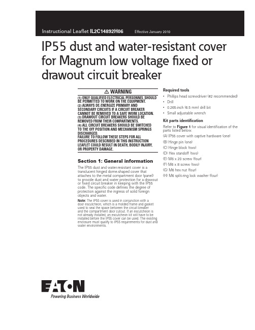
IP55 dust and water-resistant cover for Magnum low voltage fixed or drawout circuit breakerm warning(1) Only qualified electrical persOnnel shOuld be permitted tO wOrk On the equipment.(2) always de-energize primary and secOndary circuits if a circuit breaker cannOt be remOved tO a safe wOrk lOcatiOn.(3) drawOut circuit breakers shOuld be remOved frOm their cOmpartments.(4) all circuit breakers shOuld be switchedtO the Off pOsitiOn and mechanism springs discharged.failure tO fOllOw these steps fOr all prOcedures described in this instructiOn leaflet cOuld result in death, bOdily injury, Or prOperty damage.Section 1: General information The IP55 dust and water-resistant cover is a translucent hinged dome-shaped cover that attaches to the metal compartment door (panel) to provide dust and water protection for a drawout or fixed circuit breaker in keeping with the IP55 code. The specific code defines the degree of protection against the ingress of solid foreign objects and water.Note:N The IP55 cover is used in conjunction with adoor escutcheon, which is a molded frame and gasket used to seal the space between the circuit breakerand the compartment door cutout. If an escutcheon is not already installed, an escutcheon kit will have to be installed before the IP55 cover can be used. The existing enclosure must qualify to IP55 requirements for dust and water environments.Rtquirtd oNNls• Phillips head screwdriver (#2 recommended)• Drill• 0.265-inch (6.5 mm) drill bit• Small adjustable wrenchKio paros idtnoificaoiNnRefer to Figurt 1 for visual identification of the parts listed below.(A) IP55 cover with captive hardware (one)(B) Hinge pin (one)(C) Hinge block (two)(D) Hex standoff (two)(E) M6 x 20 screw (four)(F) M6 x 8 screw (two)(G) M6 hex nut (four)(H) M6 split-ring lock washer (four)2Instructional Leaflet IL2C14892H06Effective January 2010IP55 dust and water-resistant cover for Magnum low voltage fixed ordrawout circuit breakereaton corporation Figurt 1. CNnotnos Nf Kio ShNwn(A)(B)(C)(D)(E)(F)(H)(G)Section 2: installation of ip55 coverProceed with the following four steps.Sotp 1e: Locate and drill two 0.265-inch (6.5 mm) diameter mounting holes in the compartment door (panel) relative to the alreadymounted door escutcheon as shown for drawout or fixed-mounted circuit breakers.Figurt 2. Sotp 1Sotp 2e: Mount the two hex standoffs (D) using M6 x 8 mm screws (F) from behind the compartment door (panel), using the holes from Step 1.Figurt 3. Sotp 23Instructional Leaflet IL2C14892H06Effective January 2010IP55 dust and water-resistant cover for Magnum low voltage fixed or drawout circuit breakereaton corporation Sotp 3e: Mount the lexan IP55 cover (A) to the two hex standoffs installed in Step 2, using the captive hardware in the IP55 cover. This will ensure accurate positioning of the hardware to be installed next in Step 4.Figurt 4. Sotp 3Sotp 4e: Align the lower hinge block (C) by centering hinge pin hole in the end of the hinge block with the hinge pin channel of the IP55 cover. The hinge block should be flush with the hinge channel of the cover. Use the two mounting holes of the block as a template to locate the placement of two 0.265 (6.5 mm) diameter holes in the compartment door (panel). Mount the lower hinge block using two M6 x 20 screws (E), M6 hex nuts (G) and M6 washers (H). The hex nuts and washers are positioned behind the compartment door (panel). Repeat the same procedure to mount the top hinge block, while capturing the hinge pin (B) in the end holes of the lower and upper hinge blocks.Note:N The IP55 cover is shown open in Figurt 5 below for clarity purposes.Figurt 5. Sotp 4EaoNn CNrpNraoiNn Electrical Sector1000 Cherrington Parkway Moon Township, PA 15108 United States877-ETN-CARE (877-386-2273) © 2010 Eaton CorporationAll Rights ReservedPrinted in USAPublication No. IL2C14892H06 / Z9269 January 2010PowerChain Management is a registered trademark of Eaton Corporation.All other trademarks are property of their respective owners.Instructional Leaflet IL2C14892H06 Effective January 2010IP55 dust and water-resistant cover for Magnum low voltage fixed ordrawout circuit breakerDisclaimer of warranties and limitation of liabilityThe information, recommendations, descriptions, and safety notations in this document are based on Eaton Corporation’s (“Eaton”) experience and judgment, and may not cover all contingencies. If further information is required, an Eaton sales office should be consulted.Sale of the product shown in this literature is subject to the terms and conditions outlined in appropriate Eaton selling policies or other contractual agreement between Eaton and the purchaser.THERE ARE NO UNDERSTANDINGS, AGREEMENTS, WARRANTIES, EXPRESSED OR IMPLIED, INCLUDING WARRANTIES OF FITNESS FOR A PARTICULAR PURPOSE OR MERCHANTABILITY, OTHER THAN THOSE SPECIFICALLY SET OUT IN ANY EXISTING CONTRACT BETWEEN THE PARTIES. ANY SUCH CONTRACT STATES THE ENTIRE OBLIGATION OF EATON. THE CONTENTS OF THIS DOCUMENT SHALL NOT BECOME PART OF OR MODIFY ANY CONTRACT BETWEEN THE PARTIES. In no event will Eaton be responsible to the purchaser or user in contract, in tort (including negligence), strict liability, or otherwise for any special, indirect, incidental, or consequential damage or loss whatsoever, including but not limited to damage or loss of use of equipment, plant or power system, cost of capital, loss of power, additional expenses in the use of existing power facilities, or claims against the purchaser or user by its customers resulting from the use of the information, recommendations, and descriptions contained herein.The information contained in this manual is subject to change without notice.。
RCS-978系列500KV变压器保护说明书
业务联系 技术支持 工程服务 质量保证
电话:(025)3406078 3439746 传真:(025)3438965
电话:(025)3429900-2091/2093 传真:(025)3429900-2091
电话:(025)2107703 传真:(025)2100770
电话:(025)2100660
5.定值内容及整定说明.................................................................................................................. 29
5.1 装置参数定值单................................................................................................................29 5.2 RCS-978A 定值单 .............................................................................................................29 5.3 RCS-978B 定值单 .............................................................................................................38 5.4 RCS-978C 定值单 .............................................................................................................43
产品管理-魏德米勒继电器产品详细目录
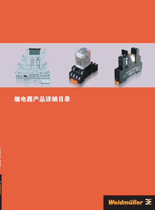
继电器产品目 录光电耦合器产品电子式时间继电器功能电子产品通讯电子产品250V/6A 12V/100mA 6.2ms/3.9ms AgSnO 2 20x106 次 0.1Hz LED 绿色/有/有 -25 °C…+55 °C -40 °C…+60 °C 40°C/93% 湿度无冷凝 CE, cURus EN 50178 300 V 4 kV ≥5.5mm III 2 是 mm 2 mm 2.5 / 0.5 / 4 1.5 / 0.5 / 2.5 93.0 / 6.1 / 92.094.0 / 6.1 / 91.0 电压 [A ] 电流 [A] 电流 [A] 电流 [A]acc.to DC 13 输出参数应用额定参数绝缘基座参数 (EN 50 178)尺寸螺钉连接弹片连接最大切换电压AC/电流 最小切换电压/电流响应时间/释放时间 触点材料 机械寿命 额定负载下的最大开关频率 状态指示/二极管/反向电压保护环境工作温度存储温度环境温度认证标准额定电压额定浪涌电压接点间爬电距离过压等级污染等级符合VDE 0106 101安全隔离 接线范围(额定/最小/最大) 长x 宽x 高负载特性曲线开关次数 开关次数1对转换触点· 该继电器可用于联接控制信号与执行器· 插拔式横联可减少联线· 6.1mm 厚· 可采用弹片式或压线框联接· 可提供镀金触头继电器(感性负载)1继电器5mA4mA190mW29V/11V29V/11V2.2mA/1.3mA2.2mA/1.3mAMRZ 48Vuc 1CO8556110000RSS 113048 48Vdc-Rel1U40616200003.3mA200mW35V/11V1.6mA/0.6mAMRZ 60Vdc 1CO8556130000RSS 113060 60Vdc-Rel1U40616300003.5mA3.5mA0.42mW71V/22V71V/22V1.8mA/0.5mA1.8mA/0.5mAMRZ 120Vuc 1CO8556100000RSS 113060 60Vdc-Rel1U40616300007.6mA1.75VA103V/49V5mA/2.5mAMRZ 230Vac 1CO8556090000RSS 113024 24Vdc-Rel1U4060120000螺钉连接型号订货号弹片连接型号订货号型号订货号38.5mA193mW3.2V/1.6V21.6mA/8mAMRZ 5Vdc 1CO8556150000RSS 113005 05Vdc-Rel1U406158000017mA210mW6.4V/2.5V8.4mA/2.4mAMRZ 12Vdc 1CO8556140000RSS 113012 12Vdc-Rel1U40616100006.6mA160mW15.4V/6.5V4mA/1.2mAMRZ 24VDC 1CO853*******RSS 113024 24Vdc-Rel1U406012000011mA6.4mA154mW15.8V/7V15.8V/7V3.6mA/1.3mA3.6mA/1.3mAMRZ 24Vuc 1CO8556120000RSS 113024 24Vdc-Rel1U4060120000 订货数据订货数据配件,插拔式继电器订货数据输入额定电压额定电流AC额定电流DC额定功率动作/释放电压AC 线圈动作/释放电压DC 线圈动作/释放电流AC 线圈动作/释放电流DC 线圈螺钉连接型号订货号弹片连接型号订货号型号订货号订货数据订货数据配件,插拔式继电器订货数据输入额定电压额定电流AC额定电流DC额定功率动作/释放电压AC 线圈动作/释放电压DC 线圈动作/释放电流AC 线圈动作/释放电流DC线圈6.6mA160mW15.4V/6.5V4mA/1.2mAMRZ 24Vdc ACT8660910000RSS 113024 24Vdc-Rel1U40601200007mA0.84VA79V/65V4.5mA/3.7mA15.6mA3.59VA117.5V/59V9.13mA/4.78mAMRZ 120Vac 1CO RC8825960000RSS 113060 60Vdc-Rel1U4061630000螺钉连接型号订货号弹片连接型号订货号型号订货号订货数据订货数据配件,插拔式继电器订货数据特殊产品输入额定电压额定电流AC额定电流DC额定功率动作/释放电压AC线圈动作/释放电压DC 线圈动作/释放电流AC 线圈动作/释放电流DC 线圈3.5mA2.5mA0.8VA /600MW146V/124V155V/1.5V1.9mA/1.5mA1.9mA/1.0mAMRZ 230Vuc 1CO8825980000RSS 113060 60Vdc-Rel1U40616300002继电器RSS 113024 24Vdc-Rel1U40601200002个转换触点250V/6A12V/10mA7ms/3msAgNi20x106次0.1HzLED 绿色/有/有-25 °C…+60 °C-40 °C…+80 °C5%...95% 湿度无冷凝CEEN 50178300 V4 kV≥5.5mmIII2是mm2mm2.5 / 0.5 / 494.2 / 14 / 94.016.7mA500mW16.8V/2.4V3.2mA0.75VA172.5V/34.5V订货数据· 该继电器可用于联接控制信号与执行器· 插拔式横联可减少联线· 14mm厚· 采用弹片式联接输出参数额定参数绝缘基座参数 (EN 50 178)尺寸弹片连接最大切换电压AC/电流最小切换电压/电流响应时间/释放时间触点材料机械寿命额定负载下的最大开关频率状态指示/二极管/反向电压保护环境工作温度存储温度环境温度认证标准额定电压额定浪涌电压接点间爬电距离过压等级污染等级符合VDE 0106 101安全隔离接线范围(额定/最小/最大)长x宽x高弹片连接型号订货号订货数据输入额定电压额定电流AC额定电流DC额定功率动作/释放电压AC 线圈动作/释放电压DC 线圈动作/释放电流AC 线圈动作/释放电流DC 线圈3继电器· 该继电器可用于联接控制信号与执行器· 插拔式横联可减少联线· 14mm厚· 采用弹片式联接250V/6A(输出并联可达10A)12V/10mA7ms/3msAgNi20x106次0.1HzLED 绿色/有/有-25 °C…+60 °C-40 °C…+80 °C5%...95% 湿度无冷凝CEEN 50178300 V4 kV≥5.5mmIII2是mm2mm2.5 / 0.5 / 494.2 / 14 / 94.016.7mA500mW16.8V/2.4V3.2mA0.75VA172.5V/34.5V订货数据输出参数额定参数绝缘基座参数 (EN 50 178)尺寸弹片连接最大切换电压AC/电流最小切换电压/电流响应时间/释放时间触点材料机械寿命额定负载下的最大开关频率状态指示/二极管/反向电压保护环境工作温度存储温度环境温度认证标准额定电压额定浪涌电压接点间爬电距离过压等级污染等级符合VDE 0106 101安全隔离接线范围(额定/最小/最大)长x宽x高弹片连接型号订货号订货数据输入额定电压额定电流AC额定电流DC额定功率动作/释放电压AC 线圈动作/释放电压DC 线圈动作/释放电流AC 线圈动作/释放电流DC 线圈4继电器250V/6A12V/10mA6.6ms/5.8msAgSnO2 5μm Au20x106次0.1HzLED 绿色/有/有-25 °C…+55 °C-40 °C…+60 °C40°C/93% 湿度无冷凝CE, cURusEN 50178300 V4 kV≥5.5mmIII2是mm2mm2.5 / 0.5 / 4 1.5 / 0.5 / 2.593.0 / 6.1 / 92.094.0 / 6.1 / 91.06.6mA160mW15.4V/6.5V4mA/1.2mAMRZ 24Vdc 1CO 5uAu8596080000RSS 112024 24Vdc-Rel1U40615900003.5mA3.5mA0.42VA71V/22V71V/22V1.8mA/0.5mA1.8mA/0.5mAMRZ 120Vuc 1CO 5uAu8652040000RSS 112060 60Vdc-Rel1U40616000007.6mA1.75VA103V/49V5mA/2.5mAMRZ 230Vac 1CO 5uAu8596070000RSS 112024 24Vdc-Rel1U4061590000订货数据· 该继电器可用于联接控制信号与执行器· 插拔式横联可减少联线· 6.1mm厚· 可采用弹片式或压线框联接· 可提供镀金触头继电器输出参数额定参数绝缘基座参数 (EN 50 178)尺寸螺钉连接弹片连接最大切换电压AC/电流最小切换电压/电流响应时间/释放时间触点材料机械寿命额定负载下的最大开关频率状态指示/二极管/反向电压保护环境工作温度存储温度环境温度认证标准额定电压额定浪涌电压接点间爬电距离过压等级污染等级符合VDE 0106 101安全隔离接线范围(额定/最小/最大)长x宽x高螺钉连接型号订货号弹片连接型号订货号型号订货号订货数据订货数据配件,插拔式继电器输入额定电压额定电流AC额定电流DC额定功率动作/释放电压AC 线圈动作/释放电压DC 线圈动作/释放电流AC 线圈动作/释放电流DC 线圈5继电器该继电器可用于连接控制信号和执行器,适用于中小型负载继电器横块可更换6.1 mm厚插拔式横联件可减少接线Cl.1 Div.2区域的防爆认证••••技术参数6光电耦合器该继电器可用于连接控制信号和执行器,适用于中小型负载继电器横块可更换6.1 mm厚插拔式横联件可减少接线Cl.1 Div.2区域的防爆认证120 VAC的继电器RC组合模块,输入端的RC组合电路可以保证安全切换,例如可防止漏电流的影响。
不间断电源KR系列(6-10kVA)手册(中文)、192VDC

第 3 章 基本原理和结构 ...................................................................................................................8 3.1 单机工作原理 ........................................................................................................................8 3.1.1 工作原理框图 ...............................................................................................................8 3.1.2 工作原理 ......................................................................................................................8 3.1.3 工作过程 ......................................................................................................................9 3.2 并联系统原理 ......................................................................................................................10 3.2.1 工作原理 ....................................................................................................................10 3.2.2 工作模式 ....................................................................................................................10 3.3 主机结构 .............................................................................................................................13 3.3.1 显示结构 ....................................................................................................................13 3.3.2 显示界面 ....................................................................................................................13 3.3.3 KR6000L、KR(/B)1110、KR(/B)3110 外形外形.....................................................15 3.3.4 KR6000、KR(/B)1110S、KR(/B)3110S 外形..............................................................18
DMF-5005NY-LY-CNE-DCN资料
T>250ƒÊ s
T•† 0 T•† ms 10
T •† 50ms
T•† 0
T•† 50ms
T •† 0
Please maintain the above sequence when turning on and off the power supply of the module. If VEE is supplied to the module while internal alternate signal for LCD driving (M) is unstable or RESET is active, DC component will be supplied to the LCD panel. This may cause damage to the LCD module.
•F min. 0•Ž •` max. 50•Ž •F min. -20•Ž •` max. 60•Ž •F 240 (W) •~ 64 (H) dots •F 0.49 (W) •~ 0.49 (H) mm •F 0.53 (W) •~ 0.53 (H) mm •F 132.0 (W) •~ 39.0 (H) mm •F 180.0 (W) •~ 65.0 (H) •~ (17.6) (D) mm •F 170g max. •F NTD-7446 ( STN / Yellow-mode / Transmissive )
T.Yuchi
Prepared by (ACI Engineering Division)
Table of Contents
1. 2. 3. 4. 5. 6. 7. 8. 9. 10. 11. General Specifications ............................................................................................................................... 2 Electrical Specifications ............................................................................................................................ 3 Optical Specifications ................................................................................................................................ 7 I/O Terminal ................................................................................................................................................... 9 Test ................................................................................................................................................................. 11 Appearance Standards ............................................................................................................................. 12 Code System of Production Lot ......................................................................................................... 15 Type Number............................................................................................................................................... 15 Applying Precautions ............................................................................................................................... 15 Precautions Relating Product Handling............................................................................................ 16 Warranty ....................................................................................................................................................... 17
AD511-2 Active Iridium Antenna User Manual
TABLE OF CONTENTS1.FCC APPROVAL (3)1.1. FCC 15.19 (A) (3) (3)1.2. FCC 15.105 (B) (3)1.3. ICES-003 (3)1.4. U SER M ANUAL N OTICE FOR L ICENSE-E XEMPT R ADIO A PPARATUS (3)2.INTRODUCTION (4)3.MOUNTING AND OPERATION (5)4.FIGURES ................................................................................................................................................................ 6, 71.FCC Approval1.1. FCC 15.19 (a) (3)This device complies with Part 15 of the FCC Rules. Operation is subject to the following two conditions: -1.This device may not cause interference, and2.This device must accept any interference, including interference that may cause undesiredoperation of the device.1.2. FCC 15.105 (b)The equipment has been tested and found to comply with the limits for a Class B device, pursuant to Part 15 of the FCC Rules. These limits are designed to provide reasonable protection against harmful interference in a residential installation.This equipment generates, uses, and can radiate radio frequency energy and, if not installed and used in accordance with the instructions, may cause harmful interference to radio communications. However, there is no guarantee that interference will not occur in a particular installation. If this equipment does cause harmful interference to radio or television reception, which can be determined by turning the equipment off and on, the user is encouraged to try to correct the interference by one or more of the following measures: -•Reorient or relocate the receiving antenna.•Increase the separation between the equipment and receiver.•Connect the equipment into an outlet on a circuit different from that to which the receiver is connected.•Consult the dealer or an experienced radio/TV technician for help.1.3. ICES-003This Class B digital apparatus complies with Canadian ICES-003.er Manual Notice for License-Exempt Radio ApparatusThis device complies with Industry Canada license-exempt RSS Standard(s). Operation is subject to the following two conditions: -1.This device may not cause interference, and2.This device must accept any interference, including interference that may cause undesiredoperation of the device.2. IntroductionIridium telephones were originally designed to operate with a passive antenna, either an element attached directly to the handset, or a remote aerial connected with a short length of coaxial cable. Unfortunately, a signal loss of more than 3dB in a remote antenna’s connecting cable degrades performance due to attenuation of both the received and transmitted signals. A 3dB loss corresponds to approximately 10m of RG213U or 3m of RG58U coaxial cable, lengths that clearly restrict the mounting options for the antenna using standard down-leads.AD511-2 active Iridium antenna (figure 1 & figure 2) is designed for use with up to 160 meters of coaxial cable terminated with type ‘N’ connectors, and with coax lengths starting from 27meters – subject to AST advice.Designed for harsh environments, the AD511-2 consists of two RHCP dipole antenna housed within a 4mm thick GRP radome mounted on a common base. One antenna is for signal transmission and one for reception.AD511-2 has a linear power amplifier within the base and connected to the transmitting antenna compensates for signal loss incurred mainly by the connecting cable. Similarly, a low noise amplifier is attached to the receiving antenna via a low loss interdigital filter to boost the signal sent to the telephone. The interdigital filter has a bandwidth of 25 MHz centered on the Iridium band designed to attenuate any out of band interference that may arise, for example from nearby Inmarsat uplinks. Using manufacturing techniques proven for a range of extremely rugged GPS/DGP active antenna, the base is milled from aluminium and hard anodised, giving an attractive grey finish, which is mechanically resilient and resistant to corrosion. The antenna’s mass is 0.8kg.3.Mounting and OperationAD511-2 should be mounted with an unobstructed view of the sky. An aluminium bracket with V-bolts is provided to attach the antenna to horizontal or vertical masts or spars up to 50mm in diameter, figure 2. The bracket is shipped inverted at the centre of the AD511-2 antenna and should be detached, inverted, then reattached to antenna case using the mounting holes in the base.The coaxial down-lead is attached to the N-type connector on the underside of the antenna, figure 2. Wrapping the connectors with self-amalgamating tape is recommended for permanent installations and the cable should be taped or strapped to the spar as appropriate.AD511-2 antenna supplied with coaxial down-leads must be used with the accompanying AD511-3 DC Power Break-In Box (figure 3), which accepts +18V to +36V DC at 500mA. The down-lead must not be shortened by the user.AD511-3 Power Break-In should be positioned close to the telephone base- station or handset. The coaxial down-lead is then attached to the N type connector on the AD511-3 (figure 3 & figure 4).Earthing: - the AD-511-3 power breaking box is provided with an earth terminal. The box should be earthed via this connection with a short earthing lead connection to the system earth. Connection between the telephone and the AD511-3 is made with a coaxial cable terminated with TNC connectors. An adapter is provided with the Iridium handset, which enables a TNC terminated cable to be attached to the telephone. AD511-3 case has drilled flanges to enable permanent fixing.A 1m flying lead for the AD511-3 Power Break-In Box is provided for connection to the DC supply (+18 to 36 v DC at 500mA), which can be trimmed (or extended) if necessary. The red wire is connected to supply positive, whilst the blue wire is for either an isolated or grounded negative supply. AD511-3 is protected against output short-circuiting by a fuse, which is resettable by disconnecting the unit from the +18 to +36 v DC supply.With all connections made, the telephone can then be turned on and used as normal - it is transmitting into a load impedance equivalent to a matched passive antenna. The gains of the antenna transmitter and receiver are factory set to compensate for the total attenuation between the telephone and the antenna, mainly determined by the coaxial down-lead. Consequently, the signal output level and frequency from the antenna is equivalent to that radiating from a passive antenna mounted directly on the handset, subject to the antenna transmitter being a linear device. Transmitter linearity is verified with test protocols using an HP 8591 EMC analyser that also ensure there are no spurious out of band emissions.4. FiguresFigure 1. AD511-2 Active Iridium antennaFigure 2. AD511-2 Active Iridium antenna with mounting bracket and coaxial down-leadFigure 3. AD511-3 Power Break-In Box for use with +18 to +36 v DC supply.The case is hard anodised aluminium and has fixing flanges. A 40m coil of RG213U cable is shown connected to an AD511-2 active antenna (top). The handset interconnect is shown trailing from the TNC to the bottom left, whilst the flying lead for connection to 18 to 36 v DC supply is shown cutting the frame to the left.Figure 4. Schematic diagram for system connections•Mount AD511-2 active antenna with clear view of sky using bracket supplied. •Attach top end of coax down-lead to N type connector on underside of antenna. •Attach bottom end of down-lead to N type connector to the Power Break-In Box AD511-3. The down-lead must not be shortened by the user. •Attach interconnect between TNC on AD510-40 and telephone (or base station) using the antenna adapter provided with the phone. •Attach DC supply lead to +18 to +36 v DC supply (600mA max). Red lead to +supply, Blue to – supply. •Turn on Iridium telephone and log-in. • The AD511-2 should only be used with the AD511-3 Break-In Box. It is not to be used with AD511or AD510-40 Break-In Boxes.。
欧姆龙RFID
RFID㋏㒳
V680㋏߫
ᷛㅒgᬒ఼᪡ݠ (FRAMൟ)
ᬒ఼g㒓 V680-HA63B V680-HS52 V680-HS63 V680-HS65
IDᷛㅒ V680-D2KF52M V680-D2KF67 V680-D2KF67M V680-D8KF68 V680-D32KF68
Undertegnede Omron erklærer herved, at følgende den RFID System, V680-HS52 Serie, V680-HS63 Serie, V680-HS65 Serie, 680-HA63B Serie overholder de væsentlige krav og øvrige relevante krav i direktiv 1999/5/EF.
RFID 系统
2
操作手册
前言
前言 ⑥请务必遵守各项使用事项和使用禁止事项,避免发生不正确使用以及由此对客户本身及第三者造成的损
害。
4.设计·规格的变更
本产品目录中记载的各项产品、附属品的设计·规格,由于各种原因,可能会根据需要进行变更,购买时请 与销售网点的人员确认实际的设计·规格。
5.服务范围
本公司产品价格中不包含技术人员派遣等服务费用。 如客户需要提供相关技术服务,可与销售网点的人员联系。
2.责任免除
①在任何情况下,对包括因本公司产品引起的特别损失、间接损失在内的一切损失本公司均不承责任。 ②使用可编程设备时,非因本公司人员进行的编程引起的全部后果,本公司不承担任何责任。
3.适合用途、条件
①本产品并不是出于维护安全目而设计的用于直接或间接探测人类的存在的产品。相关用途请使用本公司传 感器样本中记载的安全传感器。
NTMFS2D5N08X MOSFET 产品说明说明书
DATA SHEET MOSFET – Power, SingleN-Channel, STD Gate,SO8FL80 V, 2.1 m W, 181 ANTMFS2D5N08XFeatures∙Low QRR, Soft Recovery Body Diode∙Low R DS(on) to Minimize Conduction Losses∙Low QG and Capacitance to Minimize Driver Losses∙These Devices are Pb−Free, Halogen Free/BFR Free and are RoHSCompliantApplications∙Synchronous Rectification (SR) in DC−DC and AC−DC∙Primary Switch in Isolated DC−DC Converter∙Motor DrivesMAXIMUM RATINGS (T J = 25︒C unless otherwise stated)Parameter Symbol Value UnitDrain−to−Source Voltage V DSS80VGate−to−Source Voltage V GS±20VContinuous Drain Current (Note 1)T C = 25︒C I D181A T C = 100︒C128Power Dissipation (Note 1)T C = 25︒C P D148W Pulsed Drain Current T C = 25︒C, t p = 100 m s I DM761APulsed Source Current (Body Diode)I SM761Operating Junction and Storage Temperature Range T J, T STG−55 to+175︒CSource Current (Body Diode)I S224A Single Pulse Avalanche Energy(I PK = 55 A) (Note 3)E AS151mJLead Temperature for Soldering Purposes(1/8" from case for 10 s)T L260︒CStresses exceeding those listed in the Maximum Ratings table may damage the device. If any of these limits are exceeded, device functionality should not be assumed, damage may occur and reliability may be affected.1.The entire application environment impacts the thermal resistance values shown.They are not constants and are only valid for the particular conditions noted.2.Actual continuous current will be limited by thermal and electromechanicalapplication board design3.E AS of 151 mJ is based on started T J = 25︒C, I AS = 55 A, V DD = 64 V, V GS =10V, 100% avalanche testedMARKINGDIAGRAM V(BR)DSS R DS(ON) MAX I D MAX80 V 2.1 m W @ 10 V181 AN−CHANNEL MOSFETG (4)DFN5 (SO−8FL)CASE 488AA2D5N08= Specific Device CodeA= Assembly LocationY= YearW= Work WeekZZ= Lot Traceabililty†For information on tape and reel specifications, including part orientation and tape sizes, please refer to our T ape and Reel Packaging Specifications Brochure, BRD8011/D.D Device Package Shipping†ORDERING INFORMATIONNTMFS2D5N08XT1G DFN5(Pb−Free)1500 / Tape &ReelTHERMAL CHARACTERISTICSParameter Symbol Value Unit Thermal Resistance, Junction−to−Case R q JC 1.01︒C/W Thermal Resistance, Junction−to−Ambient (Notes 4, 5)R q JA394.Surface mounted on FR4 board using a 1 in2, 1 oz. Cu pad.5.R q JA is determined by the user’s board design.ELECTRICAL CHARACTERISTICS (T J = 25︒C unless otherwise specified)Parameter Symbol Test Condition Min Typ Max Unit OFF CHARACTERISTICSDrain−to−Source Breakdown Voltage V(BR)DSS V GS = 0 V, I D = 1 mA80VDrain−to−Source Breakdown Voltage (transient)D V(BR)DSS/D T JI D = 1 mA, Referenced to 25C31.6mV/︒CZero Gate Voltage Drain Current I DSS V DS = 80 V, T J = 25︒C1m AV DS = 80 V, T J = 125︒C250Gate−to−Source Leakage Current I GSS V DS = 0 V, V GS = 20 V100nA ON CHARACTERISTICSDrain−to−Source On Resistance R DS(on)V GS = 10 V, I D = 43 A 1.9 2.1m WV GS = 6 V I D = 21 A 2.9 3.7Gate Threshold Voltage V GS(TH)V GS = V DS, I D = 213 m A 2.4 3.6V Negative Threshold Temperature Coefficient D V GS(TH)/D T JV GS = V DS, I D = 213 m A,−7.5mV/︒C Forward Transconductance g FS V DS = 5 V, I D = 43 A135S CHARGES AND CAPACITANCESInput Capacitance C ISSV DS = 40 V, V GS = 0 V, f = 1 MHz 3800pFOutput Capacitance C OSS1100Reverse Transfer Capacitance C RSS17Output Charge Q OSS79nC Total Gate Charge Q G(TOT)V DD = 40 V, I D = 43 A, V GS = 6 V33V DD = 40 V, I D = 43 A, V GS = 10 V 53Threshold Gate Charge Q G(TH)12Gate−to−Source Charge Q GS18Gate−to−Drain Charge Q GD8Gate Plateau Voltage V GP 4.7V Gate Resistance R G f = 1 MHz0.8W SWITCHING CHARACTERISTICSTurn−On Delay Time t d(ON)Resistive Load, V GS = 0/10 V,V DD = 40 V, I D = 43 A, R G = 2.5 W 26nsRise Time t r9Turn−Off Delay Time t d(OFF)38Fall Time t f8DRAIN−SOURCE DIODE CHARACTERISTICSForward Diode Voltage V SD I S = 43 A, V GS = 0 V, T J = 25︒C0.82 1.2VI S = 43 A, V GS = 0 V, T J = 125︒C0.66Reverse Recovery Time t RRV GS = 0 V, I S = 43 A,dIS/dt = 1000 A/m s, V DD = 40 V 25nsCharge Time t a14Discharge Time t b11Reverse Recovery Charge Q RR183nC Product parametric performance is indicated in the Electrical Characteristics for the listed test conditions, unless otherwise noted. Product performance may not be indicated by the Electrical Characteristics if operated under different conditions.Figure 1. On −Region CharacteristicsFigure 2. Transfer CharacteristicsFigure 3. On −Resistance vs. Gate VoltageFigure 4. On −Resistance vs. Drain CurrentFigure 5. Normalized ON Resistance vs.Junction Temperature Figure 6. Drain Leakage Current vs. DrainVoltage100200300400500I D , D r a i n C u r r e n t (A )V DS , Drain to Source Voltage (V)050100150200250300350400450500I D , D r a i n C u r r e n t (A )V GS , Gate to Source Voltage (V)02468101214161820R D S (O N ), D r a i n t o S o u r c e R e s i s t a n c e (m W )V GS , Gate to Source Voltage (V)00.511.522.533.54R D S (O N ), D r a i n t o S o u r c e R e s i s t a n c e (m W )I D , Drain Current (A)0.40.60.811.21.41.61.822.2R D S (O N ), D r a i n −S o u r c e O n R e s i s t a n c e (N o r m a l i z e d )T J , Junction Temperature (°C)1101001000I D S S , D r a i n L e a k a g e C u r r e n t (n A )V DS , Drain to Source Voltage (V)Figure 7. Capacitance CharacteristicsFigure 8. Gate Charge CharacteristicsFigure 9. Resistive Switching Time Variationvs. Gate ResistanceFigure 10. Diode Forward CharacteristicsFigure 11. Safe Operating Area (SOA)Figure 12. Avalanche Current vs Pulse Time(UIS)110100100010000C , C a p a c i t a n c e (p F )V DS , Drain to Source Voltage (V)246810V G S , G a t e t o S o u r c e V o l t a g e (V )Q G , Gate Charge (nC)1e −1e −1e −1e −t , R e s i s t i v e S w i t c h i n g T i m e (s e c )R G , Gate Resistance (W )0.00010.0010.010.1110100100010000I S ,S o u r c e C u rr e n t (A )V SD , Body Diode Forward Voltage (V)10100I D , D r a i n C u r r e n t (A )V DS , Drain to Source Voltage (V)110100I A S ,A v a l a n c h e C u r r e n t (A )t AV ,Time in Avalanche (s)02Figure 13. Gate Threshold Voltage vs.Junction TemperatureFigure 14. Maximum Current vs. CaseTemperatureFigure 15. Transient Thermal Response0.60.70.80.911.11.2V T H ,G a t e T h r e s h o l d V o l t a g e (N o r m a l i z e d )T J , Junction Temperature (°C)020406080100120140160180200255075100125150175I D , D r a i n C u r r e n t (A )T C , Case Temperature (°C)0.0010.010.1110Z q J C , E f f e c t i v e T r a n s i e n t T h e r m a l I m p e d a n c e (°C /W )t, Rectangular Pulse Duration (sec)M 3.00 3.40q0 −−−_ 3.8012 _DFN5 5x6, 1.27P(SO −8FL)CASE 488AA ISSUE NDATE 25 JUN 2018SCALE 2:1NOTES:1.DIMENSIONING AND TOLERANCING PER ASME Y14.5M, 1994.2.CONTROLLING DIMENSION: MILLIMETER.3.DIMENSION D1 AND E1 DO NOT INCLUDE MOLD FLASH PROTRUSIONS OR GATE BURRS.XXXXXX = Specific Device Code A = Assembly Location Y = Year W = Work Week ZZ = Lot Traceability2 XDIM MIN NOM MILLIMETERS A 0.90 1.00A10.00−−−b 0.330.41c 0.230.28D 5.15D1 4.70 4.90D2 3.80 4.00E 6.15E1 5.70 5.90E2 3.45 3.65e 1.27 BSC G 0.510.575K 1.20 1.35L 0.510.575L10.125 REF GENERICMARKING DIAGRAM*1MAX 1.100.050.510.335.104.206.103.850.711.500.71*For additional information on our Pb −Free strategy and soldering details, please download the ON Semiconductor Soldering and Mounting Techniques Reference Manual, SOLDERRM/D.5.00 5.306.00 6.30−Free indicator, “G” or microdot “ G ”,MECHANICAL CASE OUTLINEPACKAGE DIMENSIONSADDITIONAL INFORMATIONTECHNICAL PUBLICATIONS:Technical Library:/design/resources/technical−documentation onsemi Website: ONLINE SUPPORT: /supportFor additional information, please contact your local Sales Representative at /support/sales。
美国FDA要求的DMF文件格式
DMF格式FDA要求此文件以8.5英寸*11英寸的纸张提交。
如遇平面布置图,工艺流程图,或批记录等较大纸张,需将这些页折成8.5英寸*11英寸装订(也可以用A4纸),此文件中所含的所有资料需以英文写,如原文非英文,须将原文稿及英文搞一并提交。
文件每一页须标明页码及日期。
(月/年)该申请须递交给FDA的CDER或CVM,一式两份。
公司的美国代理及制造商各保留副本。
SECTION A:地址文件ADDRESS FILE1. 企业地址提供地址,联系方式2. 生产地址提供地址,联系方式3. 相关代理3.1 本国联络人指出本国联络人,联系方式3.2 美国代理FDA要求国外生产商在美国指定一个文件代理,须明确该代理的职责。
联系方式。
联系方式应包括:名称,国家,省市,县,街道门牌号,电话,传真,电子邮件地址,甚至该原料药生产设施注册登记号。
对无菌原料药应包括进行无菌处理的区域。
SECTION B:承诺声明STA TEMENT of COMMITMENT我们承诺严格按照文件所描述的生产条件及规程生产***产品,我们承诺在生产操作中遵守cGMP.没有与文件描述不一致的地方,任何重大变更都将呈报FDA及该DMF的授权引用人征得其审核和批准。
文件每年修正一次,任何小的变化都应在修正中显示出来。
We hereby commit to producing strictly according to manufacturing conditions and procedures described in the DMF as well as cGMP.No deviation of description in this document is permitted.Any major amendment will be submitted to FDA and also submitted to the person(s) authorized to refer to the document for their review and approval.我们特此证明,我们不会在任何情况下接受违反联邦食品,药品和化妆品法案1992年修订本501(a)或(b)与本申请文件有关部分的人的服务。
爱达顿5PX G2 1000-3000VA 租赁柜台指南规格说明书
Eaton 5PX G21000-3000VA Rack-TowerGuide Specification1.1SummaryThis specification shall define the electrical and mechanical characteristics and requirements for a line-interactive, single phase, uninterruptible power system (UPS). The UPS shall provide high- quality AC power for sensitive electronic equipment loads.1.2StandardsThe UPS shall be designed in accordance with applicable sections of the current revision of the following documents.100V/110/120V/125V Units•Standard 1778, c-UL•cTUVus mark•EnergyStar 2.0 and DoEcompliant•IEEE ANSI C62.41 Category A2•FCC CFR 47, part 15 Class B•NOM -001-SCFI-2018•NOM-I-163-NYCE-2016•RoHS3•UL1778:2014•CSA C22.2 No. 107.3•EN IEC 62040-1•EN IEC 62040-2•EN 61000-3-11•EN 61000-3-12•BSMI (select models)•DCTY EN 62040-1•DCTY EN 62040-2•CISPR 32•IEC 61000-3-2•IEC 61000-3-3•IEC 62040-3•IEC 61000-3-11•IEC 61000-3-12•IEC 61000-2-2•IEC 61000-4-2 •IEC 61000-4-3 •IEC 61000-4-4 •IEC 61000-4-5 •IEC 61000-4-6 •IEC 61000-4-8 •IEC 61000-4-12 •IEC 60068-2-64 •IEC 60068-2-27 •IEC 60068-2-31200V/208V/220V/230V/240V Units•cTUVus mark•CE compliance mark •EnergyStar 2.0•EN62040-2•NOM•UKCA (select models) •BSMI (select models) •RCM•CISPR 22 Class B•RoHS3•UL1778:2014•CSA C22.2 No. 107.-14 + GI1 •EN IEC 62040-1•EN IEC 62040-2•EN61000-3-11•EN61000-3-12•EN 62040-2•DCTY EN 62040-1 •DCTY EN 62040-2 •CISPR-32•IEC 61000-3-2 •IEC 61000-3-3 •IEC 62040-3 •IEC 61000-3-11 •IEC 61000-3-12 •IEC 61000-2-2 •IEC 61000-4-2 •IEC 61000-4-3 •IEC 61000-4-4 •IEC 61000-4-5 •IEC 61000-4-6 •IEC 61000-4-8 •IEC 61000-4-12 •IEC 60068-2-64 •IEC 60068-2-27 •IEC 60068-2-311.3System Description1.3.1Modes of OperationThe UPS shall be designed to operate as a pure sinewave line-interactive system in the following modes:A.Normal – In normal operation incoming AC power is passed through to the load andmonitored for quality. If the voltage goes out of range the UPS will automatically switchinto AVR mode where the output voltage will be either bucked or boosted to appropriatelevels of operationB.Auto Voltage Regulation (AVR) – When voltage levels go above or below the Normal Modethreshold levels the UPS will either buck or boost the output voltage to keep it withinspecified parameters.C.Battery – When input power is insufficient to be adjusted by AVR mode or upon utilitypower failure, the critical AC load shall be supplied by the inverter, which obtains powerfrom the battery. There shall be no interruption in power to the critical load upon failure orrestoration of utility power.a.Cold Start capable (After initial AC power ON cycle)b.Battery deep discharge protectionc.Automatic inverter shutdown at now load capabled.Battery TestD.Recharge – Upon application of utility AC power or after restoration of utility power after anoutage the input convertor will automatically restart and begin supplying power to theinverter and the battery charger to recharge the batterya.Charger works in when input switch is offb.Protection against overvoltage1.3.2Design RequirementsA.Topology – Line InteractiveB.Waveform – Pure SinewaveC.Input Voltage Range off Battery•100-125V: 80-151 VAC (adjustable to 70-153V)•208V: 160-266 VAC (adjustable to 150-294V)D.Frequency – 50/60Hz Auto SensingE.Frequency Range•50Hz: 46-70Hz•60Hz: 57-70HzF.Output (User configurable)•120V units: 100/110/120/125V•208V units: 200/208/220/230/240VG.Output Load CapacityModel VA Wattage (W)5PX1000RTG2 5PX1000RTNG2 1000 10005PX1500RTG2 5PX1500RTNG2 1440 14405PX1500HRTG2 1500 15005PX2000RTG2 5PX2000RTNG2 1950 19505PX2000RT3UNG2 1950 1950 5PX2200HRTG2 2200 22005PX3000HRTG2 5PX3000HRTNG2 5PX3000RTG2 5PX3000RTNG2 3000 30005PX3000RT3UNG2 3000 3000H.Internal Battery – Valve-regulated, non-spillable, lead acid cells, maintenance freeI. Battery replacement – Hot swappable internal batteriesJ.Advanced Battery Management – The UPS will provide Advanced Battery Management that uses sophisticated sensing circuitry and a three-stage charging technique that extends the used service life of the UPS batteries while optimizing the battery recharge time.Additionally, the UPS should be able to provide up to 60 days’ notice of the end of useful battery service live to aid in scheduling of battery replacementK.Efficiency – Line mode efficiency will have minimum values as stated belowLoad %50% 75% 100%5PX1000RTG2/5PX1000RTNG2 98% 98% 98%5PX1500RTG2 / 5PX1500RTNG2 / 5PX1500HRTG2 98% 98% 98%5PX2000RTG2 / 5PX2000RTNG2 98% 98% 98%5PX2200HRTG2 98% 98% 98%5PX3000HRTG2 / 5PX3000HRTNG2 98% 98% 98%5PX3000RTG2 /5PX3000RTNG298% 98% 98% 5PX3000RT3UNG2 98% 98% 98% L.Runtime will meet the minimum requirements at the given loads.Load (W) Minimum runtime (min)5PX1000RTG2 / 5PX1000RTNG2 1000 65PX1500HRTG2 / 5PX1500RTG2 / 5PX1500RTNG2 1440 55PX2000RT3UNG2 1950 45PX2000RTG2 / 5PX2000RTNG2 / 1950 45PX2200HRTG2 2200 35PX3000HRTG2 /5PX3000RTG2 /5PX3000RTNG23000 35PX3000RT3UNG2 3000 3M.Switched Load Segments – The UPS will provide switched load segments that provide the capability to do sequenced startup and load shedding of attached devices.N.Managed Load Segments – The UPS will provide detailed power consumption measurements for each individual managed load segment.O.Auto Battery Test – The UPS will perform an auto battery test with a factory default set at once per week to determine the overall health of the battery. This interval should besettable to select either no test, every day, every week, or every month.P.Accessories•The UPS will have a compatible maintenance bypass switch.•The UPS will have the ability to add up to 4 Extended Battery Modules (EBM). The UPS will be able to auto detect the number of attached EBM’s with RJ-11 cable included. Optional AccessoriesCatalog Number Description102007018-5591 Two-post rack mounting kit (supports 2U models only)RK4PRS Ship-in-rack 4-post rail kit (required to ship 5PX G2 while mounted in a rack on a shock palletNETWORK-M2 Gigabit Network CardINDGW-M2 Industrial Gateway Card (Modbus + Relays + Network ManagementRELAY-MS Relay / Serial Interface CardEMPDTH1C2 Environmental Monitoring Probe (EMP) Gen 2 for use with NETWORK-M2 orINDGW-M2EBMCBL48RT 5PX G2 2M EBM extension cable for 48V EBMs (use with 1-1.5kVA models) EBMCBL72 5PX G2 2M EBM extension cable for 72V EBMS (use with 2-3kVA models)1.4Communications Options1.4.1Network CommunicationsThe UPS shall include one communications slot that will allow the operator to field install an optional network communications card [Eaton Network-M2 or equivalent]. The network communications card must be hot-installable. Minimum features are described below.•Communicates with SNMPv3 and IPv6•Supports IETF UPS MIB•Supports redundant UPS configurations•Allows control of UPS managed load segments•Manual and scheduled on/off controls of UPS•Capable of mass firmware upgrades•Capable for mass configuration1.4.2RS232 serial communicationThe UPS will provide a RS232 serial connection. Cable provided to provide DB-9 interface1.4.3USBThe UPS will provide a USB connection that is HID compliant for network connection1.4.4RPO / ROO (Remote Power Off / Remote On/Off)The UPS will provide both Remote Power Off and Remote On/Off capability.•Remote Power Off – Allow a remote contact to be used to disconnect power to the UPS and all devices attached. Restarting the UPS requires manual intervention.•Remote On/Off – Allows remote contact to be used to turn the UPS On and Off.1.5Management SoftwareThe UPS will be compatible with Eaton power management software suite [Eaton Intelligent Power Software or equivalent]. This software will perform the following actions:•Monitors power consumption at the load segment level•Support redundant UPS configuration•Lightweight software, not running in JRE•Performs mass configurations on alarms, alert notifications and shutdown parameters•Mass update of network card firmware•Plugs into dashboard of major Virtualization players. Allows for monitor of power equipment through the same dashboard that the Virtualized data center uses.•Triggers movement of virtual machines to avoid shutdown of server facing imminent power disruption1.6WarrantyThe UPS will have a warranty that covers both the UPS and the internal batteries for 3 years with product registration.1.7Display and ControlsThe UPS shall be provided with a full graphical LCD display that provides the information and access to all settings, control features of the UPS, and at-a-glance LED status bar for quick and easy status updates.1.7.1Input ControlsControls will consist of a 5-button configuration including:A.ESC – Exit menu item / cancel changesB.UP – Go to previous screen or menu/value selectionC.DOWN – Go to next screen of menu/value selectionD.ENTER – Enter menu or select valueE.On/Off Button1.7.2Status ScreenThe main status screen shall include all the following information at a single view:A.Load information:a.Load Percentageb.Load Wattagec.Load VAd.Graphical representation of load %B.Battery Conditiona.Estimated Runtimeb.Battery Charge Percentagec.Number of EBM’s connectedd.Graphical representation of battery %C.UPS mode statusD.Status / Alert / Alarm conditions1.7.3LED Status BarThe LED status bar shall include all the follow indications for a quick at-a-glance view of unit status:A.Blue (Nominal) – Normal operationB.Blinking Blue (Warning) – Your attention is neededC.Red (Alarm) – A critical issue needs your immediate attention and actionD.Blinking Red (Fault) – A critical issue needs your immediate action1.7.4Measurements, Controls and SettingsAll controls and settings of the UPS will be accessible through the LCD display. These will include: Measurements – Total Load, Load (Primary), Load (Group 1), Load (Group 2), Input/Output Voltage and Frequency, Battery Condition, Efficiency, Average Power Consumption Total/Primary,Group1/Group2, Cumulative Power Consumption Total, Since Primary, SinceGroup1/Since Group2Control – Load segment control, Battery Test, Change battery, Connectivity test, Reset fault state, Restore factory settings, Reset power usage, Reset battery life, Card reset,Settings – Local Settings, Input and Output Settings, On/Off settings, Battery Settings, Communication SettingsEvent Log – View alarms, events, View all events and faults stored, clear all fault and events stored Fault Log – Fault list, Reset Fault logIdentification – Product Type/Model, Part/Serial #, UPS/NMC Firmware revision, COM card IPv4, COM card IPv6, COM card MACRegistration – Links to Eaton registration website1.8Environmental conditionsA.Temperature•Storage: -15°C to 50°C•Operation: 0°C to 40°CB.Relative Humidity•Storage: 20% to 95% non-condensing•Operation: 20% to 95% non-condensingC.Audible Noise•On utility power fully charged: <40dBA•On AVR mode: <45dBA•On battery mode: <45dBA, 50dBA for 3K1.9 Mechanical featuresThe UPS configuration will provide both rack and tower mounting options. For the rack configurations rail kits and mounting hardware will be included. For tower configuration stabilizing feet will be included. All additional mounting options can be purchased separately.Catalog NumberDescription102007018-5591 Two-post rack mounting kit (supports 2U models only)RK4PRS Ship-in-rack 4-post rail kit (required to ship 5PX G2 while mounted in a rack on a shock palletAll additional input and output connections, dimensions and weights shall follow in the table below.Catalog Number Input connection OutputreceptaclesDimensions H x W x D inNet Weight lbs. 120V, 50/60 Hz5PX1000RTG2 5PX1000RTNG2 5-15P (10ft) (8) 5-15R3.4 x 17.4 x 20.6625PX1500RTG2 5PX1500RTNG2 65 5PX2000RTG2 5PX2000RTNG2 5-20P (10ft) (8) 5-20R655PX3000RTG2 5PX3000RTNG2L5-30P (10ft)(1) L5-30R (6) 5-20R3.4 x 17.4 x 25.4875PX3000RT3UNG25.1 x 17.4 x 19.686 208/230V, 50/60 Hz5PX1500HRTG2 C14-10A (8) C13-10A3.4 x 17.2 x 17.649 5PX2200HRTG2C20-16A(2) C19-16A (8) C13-10A3.4 x 17.2 x 20.6 625PX3000HRTG2 5PX3000HRTNG23.4 x 17.2 x 23.770Extended BatteryModulesFor use withMax qty / UPSDimensions H x W x D inNet Weight lbs.5PXEBM48RTG25PX1000RTG2 5PX1000RTNG2 5PX1500RTG2 5PX1500RTNG2 5PX1500HRTG243.4 x 17.2 x 17.6615PX2000RTG2 5PX2000RTNG2 5PX3000RTG23.4 x 17.2 x 23.7895PXEBM72RTG2 5PX3000RTNG25PX2200HRTG25PX3000HRTG25PXEBM72RT3UAG2 5PX2000RT3UNG25PX3000RT3UNG25PX3000HRTNG25.1 x 17.2 x 19 88。
安捷伦科技贸易(上海)有限公司全氟三丁胺MV-T-50010-30059化学品安全技术说明书
Perfluorotributylamine, Part Number MV-T-50010-30059*************(24小时)化学品安全技术说明书GHS product identifier 应急咨询电话(带值班时间)::化学名:全氟三丁胺供应商/ 制造商:安捷伦科技贸易(上海)有限公司中国(上海)外高桥自由贸易试验区英伦路412号(邮编:200131)电话号码: 800-820-3278传真号码: 0086 (21) 5048 2818Perfluorotributylamine, Part Number MV-T-50010-30059化学品的推荐用途和限制用途MV-T-50010-30059部件号:安全技术说明书根据 GB/ T 16483-2008 和 GB/ T 17519-2013GHS化学品标识:全氟三丁胺, 部件号 MV-T-50010-30059推荐用途供分析化学实验室使用的试剂和标准1 x 1 ml(毫升) 样品瓶:有关环境保护措施,请参阅第 12 节。
物质或混合物的分类根据 GB13690-2009 和 GB30000-2013紧急情况概述液体。
[吸湿的。
]透明。
无气味的。
如误吸入: 如感觉不适,呼叫解毒中心或医生。
如发生皮肤刺激: 求医要么就诊。
如仍觉眼刺激:求医要么就诊。
不易生物降解。
H315 - 造成皮肤刺激。
H319 - 造成严重眼刺激。
H335 - 可能造成呼吸道刺激。
物理状态:颜色:气味:生物降解性:GHS危险性类别警示词:警告危险性说明:H315 - 造成皮肤刺激。
H319 - 造成严重眼刺激。
H335 - 可能造成呼吸道刺激。
:防范说明标签要素象形图H315皮肤腐蚀/刺激 - 类别 2H319严重眼损伤/眼刺激 - 类别 2AH335特异性靶器官毒性 一次接触 (呼吸道刺激) - 类别 3P271 - 只能在室外或通风良好之处使用。
P261 - 避免吸入蒸气。
SVG中文说明书
危险!
在一次系统带电运行时,绝对不允许将与装置连接的电流互感器二次开路。该回路开路可能会 产生极端危险的高压。
警告!
z 曝露端子 在装置带电时不要触碰曝露的端子等,因为可能会产生危险的高电压。
z 残余电压 在装置电源关闭后,直流回路中仍然可能存在危险的电压。这些电压需在数秒钟后才会消失。
购买产品,请联系: 电话:025-87178911,传真: 025-52100511、025-52100512 电子信箱:market@
技术支持,请联系: 电话:025-52107703、8008289967、4008289967 传真:025-52100770 或登陆网站:/ser_sup
本手册中将会用到以下指示标记和标准定义:
危险! 意味着如果安全预防措施被忽视,则会导致人员死亡,严重的人身伤害,或 严重的设备损坏。
警告! 意味着如果安全预防措施被忽视,则可能导致人员死亡,严重的人身伤害, 或严重的设备损坏。
警示! 意味着如果安全预防措施被忽视,则可能导致轻微的人身伤害或设备损坏。 本条特别适用于对装置的损坏及可能对被保护设备的损坏。
151标准配置151标准配置表组件名称配置数量备注启动装置连接电抗器连接变压器连接电抗器每相1台连接变压器1台技术资料见装箱清单用户手册及必要的图纸资料152可选配置152可选配置表组件名称配置数量备注概述南京南瑞继保电气有限公司作为固定补偿用保护柜作为连接变压器或固定电容器补偿的保护开关柜备用功率单元用户自选方便维护连接电缆用户自选视柜外连接需要时选用后台系统需要远程操作控制时选用用户的其他特殊要求可进行协商技术参数南京南瑞继保电气有限公司技术参数21电气参数额定工作电压6kv10kv35kv额定容量50mvar50mvar输出无功范围从感性额定无功到容性额定无功范围内连续变化响应时间10ms输出电压总谐波畸变率3输出电流总谐波畸变率3输出电压不对称度3效率9922环境条件温度2040保证正常工作贮存环境温度2040湿度最湿月的月平均最大相对湿度小于95大气压力80kpa110kpa相对于海拔高度为2km及以下抗地震能力地面水平加速度
ChemSafe
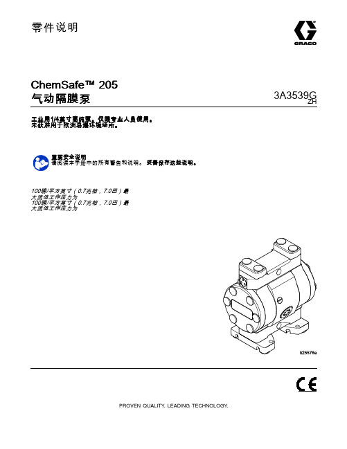
零件说明ChemSafe™205气动隔膜泵3A3539G ZH 工业用1/4英寸高纯泵。
仅限专业人员使用。
未获准用于欧洲易爆环境场所。
重要安全说明请阅读本手册中的所有警告和说明。
妥善保存这些说明。
100磅/平方英寸(0.7兆帕,7.0巴)最大流体工作压力为100磅/平方英寸(0.7兆帕,7.0巴)最大流体工作压力为PROVEN QUALITY.LEADING TECHNOLOGY.Contents警告 (3)配置编号表格 (6)安装 (8)一般信息 (8)拧紧紧固件 (8)减少气蚀秘诀 (8)安装泵 (9)系统接地 (10)空气管路 (10)排气通风 (11)流体供应管路 (12)流体出口管路 (12)操作 (13)拧紧紧固件 (13)首次使用前冲洗泵 (13)起动和调节泵 (13)泄压步骤 (14)关闭泵 (14)维护 (15)维护计划 (15)润滑 (15)拧紧螺纹连接处 (15)冲洗和储存 (15)故障排除 (16)修理 (18)拆卸流体部分 (18)拆卸中心部分 (19)重新装配中心部分 (19)重新安装流体部分 (20)扭矩说明 (22)部件 (24)配件包 (26)尺寸 (27)性能图表 (28)技术数据 (29)23A3539G警告警告以下为针对本设备的设置、使用、接地、维护及修理的警告。
惊叹号标志表示一般性警告,而各种危险标志则表示与特定操作过程有关的危险。
当本手册正文中或警告标记上出现这些符号时,请回头查阅这些警告。
若产品特定的危险标志和警告未出现在本节内,则可能出现在本手册的其他章节。
3A3539G3警告43A3539G警告3A3539G5配置编号表格配置编号表格检查铭牌(ID),查看泵的配置编号。
使用下表定义泵组件。
示例配置编号205PT-P01APT3PTPTPOPT205PT P01A PT3PT PT PO PT泵型号中心部分和空气阀流体盖和歧管阀座阀球隔膜歧管和阀座密封垫泵中心部分和空气阀材料流体盖和歧管205PT1/4英寸PTFE P01A带NPT空气入口的聚丙烯中心PT3PTFE,常温常压205UH1/4英寸UHMWPE P03A带bspt空气入口的聚丙烯中心PT4PTFE,bsptUH3UHMWPE,常温常压UH4UHMWPE,bspt阀座材料阀球材料隔膜材料歧管和阀座密封材料PT PTFE PT PTFE BN丁纳橡胶PT PTFEEP三元乙丙橡胶PO超模压PTFE63A3539G配置编号表格型号型号泵空气与流体连接螺纹流体盖和歧管球与阀座隔膜歧管密封件24X430‡英制锥螺纹24X429‡1/41/4英英寸常温常压标准管螺纹PTFE24X511英制锥螺纹24X509标准管螺纹二次成型PTFE/EPDM24X532英制锥螺纹24X533标准管螺纹三元乙丙橡胶24X508英制锥螺纹24X5071/41/4英英寸UHMWPE 标准管螺纹UHMWPTFE丁纳橡胶PTFE‡ 符合 FDA3A3539G 7安装安装一般信息所示的典型安装仅用作系统组件的选择和安装指南。
- 1、下载文档前请自行甄别文档内容的完整性,平台不提供额外的编辑、内容补充、找答案等附加服务。
- 2、"仅部分预览"的文档,不可在线预览部分如存在完整性等问题,可反馈申请退款(可完整预览的文档不适用该条件!)。
- 3、如文档侵犯您的权益,请联系客服反馈,我们会尽快为您处理(人工客服工作时间:9:00-18:30)。
T.Yuchi
Prepared by (ACI Engineering Division)
Table of Contents
1. 2. 3. 4. 5. 6. 7. 8. 9. 10. 11. General Specifications ............................................................................................................................... 2 Electrical Specifications ............................................................................................................................ 3 Optical Specifications ................................................................................................................................ 6 I/O Terminal ................................................................................................................................................... 8 Test ................................................................................................................................................................. 10 Appearance Standards ............................................................................................................................. 11 Code System of Production Lot ......................................................................................................... 14 Type Number............................................................................................................................................... 14 Applying Precautions ............................................................................................................................... 14 Precautions Relating Product Handling............................................................................................ 15 Warranty ....................................................................................................................................................... 16
0•… t
SIGNAL
VCC
0•… t
SIGNAL (Without RESET Signal)
2.4.3. Reset Sequence
SIGNAL LEVEL H Level RESET L Level VCC VCC VADJ VSS VCC VADJ
Power On Reset Reset Cancellation Power Off
RoHS regulation•@•@ To our best knowledge, this product satisfies material : requirement of RoHS regulation. Our company is doing the best efforts to obtain the equivalent certificate from our suppliers.
DMF5005N-COE-DDN
(DD)
No.2005-0284
OPTREX CORPORATION
Page 2/16
芯天下--/
2. Electrical Specifications
2.1. Absolute Maximum Ratings VSS=0V Parameter Supply Voltage (Logic) Supply Voltage (LCD Drive) Input Voltage VI
•F min. 0•Ž •` max. 50•Ž •F min. -20•Ž •` max. 60•Ž •F 240 (W) •~ 64 (H) dots •F 0.49 (W) •~ 0.49 (H) mm •F 0.53 (W) •~ 0.53 (H) mm •F 132.0 (W) •~ 39.0 (H) mm •F 180.0 (W) •~ 65.0 (H) •~ 12.0 max. (D) mm •F 170g max. •F NRD-7446 ( STN / Neutra-mode / Reflective )
SIGNAL LEVEL VCC VCC
0•… t
VSS VCC VSS VCC
SIGNAL (Without RESET Signal)
0•… t
VADJ VEE
VSS VADJ VEE
2.4.2. OFF Sequence
LEVEL VCC VSS VCC VSS VCC VSS VADJ VEE VADJ VEE
Viewing Angle Control LSI Data Transfer Backlight Drawings
•F 6:00 •F T6963C-0101 (Produced by TOSHIBA) •F 8-bit parallel data transfer •F None •F Dimensional Outline UE-31806C
T>250ƒÊ s
T•† 0 T•† ms 10
T •† 50ms
T•† 0
T•† 50ms
T •† 0
Please maintain the above sequence when turning on and off the power supply of the module. If VEE and/or VADJ is supplied to the module while internal alternate signal for LCD driving (M) is unstable or RESET is active, DC component will be supplied to the LCD panel. This may cause damage to the LCD module.
•|
Max. •| •| •| •| •| 150 50
Units ns ns ns ns ns ns ns
tCDS tCDH tCE, tRD, tWR tDS tDH tACC tOH
10
C/D
tCDS
tCDH
CE
tCE, tRD, tWR
RD, WR
tDS
D0 •D7 (WRITE)
tDH
tACC
•|
Symbol VCC -V SS
Conditions
•|
Min. -0.3
Max. 7.0
Units V
VCC -V EE
•|
0
28.0
V
-0.3
VCC +0.3
V
2.2. DC Characteristics Ta=25•Ž VSS=0V , Parameter Supply Voltage (Logic) Supply Voltage (LCD Drive) High Level Input Voltage Low Level Input Voltage High Level Output Voltage Low Level Output Voltage ICC Supply Current IEE VCC -V EE=13.0V •| 1.0 10.0 mA VCC -V SS=5.0V •| 7.0 20.0 mA VOL IOL=0.75mA 0 •| 0.3 V VOH IOH =-0.75mA VCC -0.3 •| VCC V VIL VCC =5.0V •}10% 0 •| 0.8 V VIH VCC =5.0V •}10% VCC -2.2 •| VCC V VCC -V EE Shown in 3.1 V Symbol VCC -V SS Conditions
D0 •`D7 (READ)
tOH
DMF5005N-COE-DDN
(DD)
