玻璃配方设计与调整(GFDA-SYSTEM)说明书
玻璃成分设计与调整(一)
l 玻 璃成分设 计 的原 理
1 1 玻璃成分设计的重要性 .
玻璃成分对玻璃材料或产品的功能 、 性质和成本均产生重大 的影 响, 如特硬质 仪器玻璃根据使用 条件 , 要求玻璃线膨胀系数为( 2 3 ) 1 ~, 3 — 3 × 0 此时必需设计低碱高 硅的玻璃 成分, 以达 到玻 璃制品的性质和功能
的 要求 。
玻璃成分不仅决定 了玻璃制品的性质和功能 , 而且很大程度上还决定 了成本。如特 种玻璃成分 中按照 性质要求 , 需引人稀土元素 成分, 价格昂贵 , 在设计成分时选用性质相近的其他成分代替稀土元素 , 则可降低 成本 。所 以成 分设计不 当, 会造成产 品质量下降 , 品增加 , 废 成本 提高。 玻璃成分与生产工艺也有密切关系 , 通常根据设计的成分来选择生产工 艺, 但对 于已确定 的生产 工艺 , 则需根据生产工艺来选择相应的玻璃成分。玻璃成分设计不合适 , 会使熔制 、 形困难 , 成 退火不 良, 严重 时无 法进行生产 。例如用池窑连续生产矿渣微晶玻璃板材 时, 玻璃成 分设计不妥 , 池窑的某 些部位 可能产生整 在 体析 晶, 此时只得停止生产 。其 他玻 璃品种也有 因析晶而影响生产的, 不过不象 矿渣微晶玻璃那 样严 重。至 于玻璃成分设计不 当, 造成熔 化困难 , 熔制时发生结 石、 条纹 、 泡等缺陷 , 际生产 中时有发生 。所 以一般 气 实 情况下根据设计 的玻璃成分来制定生产工艺, 但对于生产工艺已确定的工厂 , 则根据生产工艺来 选择与其相
一
. 卜、、
O
I
图1 —1 玻璃形成物 、 调整物在周期表上位置
组成 图中用曲线画出形成玻璃区域 , 图不同于相 此 图, 仅指 出了能形成玻璃 的区域 , 未指 出结 晶相及结晶温度 , 并 由于实验方法不 同, 所得结果也 稍有差异 , 但 主要的形成 区域不同学者 研究 是相 同的。 图 1 为 N O—EO— i 玻璃形成范 围, 为玻 —2 a S 1 璃形成范围线 , 以上 成分可成 玻璃 , 为 玻璃制 造范 线 2 围 , 为古代玻璃 成分范 围, 3 4为低共熔物 。由此可知 , 钠钙玻璃实用 成分 范围为 s 6 % 一8 %, a % 一 i 0 0 CO 5
玻璃成分设计与调整(三)
式 中 A一 玻璃性 质 C一玻 璃成 分
在各学者的计算系数中以干福熹ahhgh给出的玻璃组分数目比较多可计算性质也比较准确因此国内大都以该学者提出的数学模型进行结构化程序设计以吴锡琪李立华研究的结构化程序设计为例由一主程序和若干子程序组成主程序主要实现对话输入自动查表和控制转向功能其图21玻璃性质计算框图它计算由各子程序完成其程序框图如图21所示
利用数据库和知识库进行玻璃成分设计 , 首先根据要求的性能指标 , 对数据库进行查询 , 如查询成功 , 则 利用 优化 系统 选择 出最合 适成分 , 如查询 不到 , 就采 用成 分一性 质之 间的经验关 系式进 行 计算 , 种利 用数 这 据库进行成分设计 的方法 , 称为计算机辅助设计 , 对玻璃成分设计是比较切实可行 的, 我国已在设计部门和
传统 的玻璃成分设计方法基本是依靠经验 , 实质上是一种“ 筛选法”或称“ ( 炒菜法” 。运用大量原始资 ) 料, 找出性质上基本符合要求的成分 , 然后再通过计算或试验来进行 比较 , 直到选择出符合要求性质的成分
为止 。随着材 料科学 的发展 , 已对材料 微观结 构进行 了深入 的研 究 , 步找出 了成分一结 构一性 质之 间的规 逐
整的 专家 系统 。
( 利用计算机模拟进行玻璃成分设计 3 ) 计算机模拟(o pt m li ) cm u r iu tn 又称计算机实验 , e s ao 是指利用计算机对真实 的玻璃成分系统进行模拟实
验, 提供 实验结 果 , 以指导成分 设计 。
一
目 已利用分子动力学计算机模拟了氟化物玻璃微结构 , 前 可以计算出不同成分氟化物玻璃的红外 吸收 光谱 , 从而为玻璃成分设计提供依据。但对其他工业玻璃还不能适用, 今后还需进一步研究 。 玻璃成分 的计算机辅助设计起源于 7 年代 , gs 用计算机进行了 BO 0 一S 2 0 Ju h a e a 一 : i 系统光学玻璃的 0
新型玻璃工艺技术手册
新型玻璃工艺技术手册作者:编委会出版社:四卷opy出版日期:2009年5月开本:16开册数:四卷光盘数:0定价:998元优惠价:468元进入20世纪,书籍已成为传播知识、科学技术和保存文化的主要工具。
随着科学技术日新月异地发展,传播知识信息手段,除了书籍、报刊外,其他工具也逐渐产生和发展起来。
但书籍的作用,是其他传播工具或手段所不能代替的。
在当代, 无论是中国,还是其他国家,书籍仍然是促进社会政治、经济、文化发展必不可少的重要传播工具。
详细介绍:一、玻璃成分设计与改组第一章概论第一节玻璃成分的内涵第二节形成玻璃的条件第三节玻璃成分的分类第二章玻璃成分与性质的关系及其计算机第一节玻璃成分与性质关系第二节根据玻璃成分计算性质的方法第三章根据玻璃成分计算玻璃主要性质第一节玻璃密度的计算第二节玻璃热学性质的计算第三节玻璃光学性质的计算第四节玻璃机械性质的计算第五节玻璃电学性质的计算第六节玻璃化学稳定性的计算第七节玻璃熔体性质的计算第八节玻璃析晶性质的计算第九节用计算机进行玻璃性质的计算第四章玻璃成分的设计与调整方法第一节玻璃成分设计原则与方法第二节玻璃成分调整的依据第三节玻璃成分调整方法第五章平板玻璃成分设计与调整第一节浮法玻璃成分调整第二节拉制法玻璃成分调整第三节压延玻璃成分调整第四节各种平板玻璃成分调整第六章瓶罐玻璃成分设计与调整第一节瓶罐玻璃的品种和分类第二节瓶罐玻璃成分要求第三节各种瓶罐玻璃成分调整第七章器皿玻璃成分设计与调整第一节器皿玻璃品种第二节普通器皿玻璃成分调整第三节晶质玻璃成分调整第四节耐热餐具、炊具玻璃成分调整第八章仪器玻璃成分设计与调整第一节仪器玻璃的要求和分类第二节特硬质玻璃成分调整第三节硬质玻璃的成分与性能第四节一般仪器玻璃成分与性能第五节特殊仪器玻璃成分调整第九章眼镜玻璃成分设计与调整第一节眼镜玻璃的性能与分类第二节白托眼镜玻璃成分调整第三节光致变色眼镜玻璃成分调整第四节有色眼镜玻璃成分调整第十章有色玻璃成分的设计与调整第一节有色玻璃的颜色表示方法第二节有色玻璃着色机理及影响因素第三节有色玻璃成分调整第四节金星玻璃成分调整第十一章乳浊玻璃成分设计与调整第一节乳浊玻璃的分类第二节玻璃乳浊的机理第三节乳浊玻璃的成分调整第十二章医药用玻璃的成分设计与调整第一节对医药用玻璃的要求和分类第二节安瓿玻璃成分调整第三节中性玻璃成分调整第十三章电真空玻璃和电子玻璃成分设计与调整第一节对电真空玻璃和电子玻璃成分的要求第二节封接玻璃成分调整第三节电光源玻璃成分调整第四节阴极射线管玻璃成分调整第五节焊料玻璃成分调整二、玻璃配方计算与缺陷分析处理第一章玻璃原料和玻璃配方计算第一节原料的种类和性质第二节玻璃配方计算及要求第三节玻璃配合料制备工艺及控制第二章玻璃熔制工艺与控制第一节玻璃的熔制过程第二节影响玻璃熔制的主要工艺因素第三节玻璃熔窑设计第三章玻璃缺陷分析处理第一节澄清机理及产生气泡的原因第二节玻璃产生条纹的原因第三节玻璃结石的种类及产生的原因第四节玻璃质量的控制三、玻璃性能实验检测第一章玻璃工艺综合实验检测第一节玻璃材料的制备工艺及性能测定第二节风冷钢化玻璃的加工及性能检测第三节玻璃封接工艺及性能检测第四节玻璃的彩饰工艺实验第二章玻璃物理化学性能测试第一节玻璃配合料均匀度的测度第二节玻璃软化点的测定第三节玻璃密度的测定第四节玻璃应力的定量测定第五节玻璃退火温度的测定第六节玻璃折射率的测定第七节玻璃透光率和光谱曲线的测定第八节玻璃热稳定性的测定第九节玻璃热膨胀系数的测定第十节玻璃抗水、抗碱化学稳定性的测试第十一节玻璃析晶温度的测定编号25426 第十二节玻璃高频介电损耗的测定第十三节玻璃瓶耐冲击强度测定四、浮法玻璃工艺与缺陷分析处理第一章浮法玻璃原料工艺及其设备第一节浮法玻璃的化学成分及原料第二节浮法玻璃生产原料及质量要求第三节浮法玻璃原料均化第四节浮法玻璃配合料制备第二章浮法玻璃的熔制与熔窑设计第一节浮法玻璃的熔制工艺原理第二节浮法玻璃熔窑设计第三节燃烧器的选型及其安装布置第四节仪表及自动控制第五节熔窑操作及控制第六节熔窑的热修与事故应急处理第七节事故应急处理第三章浮法玻璃成型工艺及设备第一节浮法玻璃成型过程及对锡槽的要求第二节浮法玻璃成型原理第三节浮法玻璃成型工艺第四节浮法玻璃工作原理第五节浮法玻璃作业制度第六节锡槽与附属设备第七节自动控制与操作规程及生产控制第八节成型过程对玻璃质量的影响第九节锡槽设计与计算第四章浮法玻璃的退火工艺第一节浮法玻璃的退火原理第二节浮法玻璃退火技术的回顾与展望第三节退火窑的分区及传动第四节玻璃在退火窑出现的问题及解决方法第五节在线镀膜第六节仪表及自动控制第七节生产控制与操作规程第五章冷端设备及自动控制第一节冷端的工艺原理第二节冷端设备的功能和结构第三节工艺指标及操作要求第四节仪表及自动控制第六章浮法玻璃缺陷分析与处理第一节浮法玻璃缺陷的分类第二节原料及熔化部位产生的缺陷处理第三节成型缺陷处理第四节退火过程中的缺陷处理五、其它玻璃技术与性能第一章安全玻璃制造及特点第一节钢化玻璃制造特点第二节夹层玻璃制造特点第三节防弹防盗玻璃制造特点第四节防火玻璃制造特点第五节防护玻璃制造特点第二章安全玻璃产品检测标准第一节钢化玻璃标准第二节夹层玻璃标准第三节防火玻璃标准第四节汽车安全玻璃标准第五节铁道车辆、船舶等用安全玻璃标准第六节飞机用安全玻璃标准第七节防弹玻璃标准第八节居室用玻璃台盆、台面标准第三章微晶玻璃生产工艺第一节微晶玻璃生产原料第二节微晶玻璃制备工艺方法第三节烧结法微晶玻璃的生产装备第四节微晶玻璃的缺陷及质量控制第四章微晶玻璃的性能第一节密度第二节力学性质第三节热学性质第四节电学性质第五节化学性能第六节光学性能新型玻璃工艺技术手册新型玻璃工艺技术手册新型玻璃工艺技术手册一、玻璃成分设计与改组第一章概论第一节玻璃成分的内涵第二节形成玻璃的条件第三节玻璃成分的分类第二章玻璃成分与性质的关系及其计算机第一节玻璃成分与性质关系第二节根据玻璃成分计算性质的方法第三章根据玻璃成分计算玻璃主要性质第一节玻璃密度的计算第二节玻璃热学性质的计算第三节玻璃光学性质的计算第四节玻璃机械性质的计算第五节玻璃电学性质的计算第六节玻璃化学稳定性的计算第七节玻璃熔体性质的计算第八节玻璃析晶性质的计算第九节用计算机进行玻璃性质的计算第四章玻璃成分的设计与调整方法第一节玻璃成分设计原则与方法第二节玻璃成分调整的依据第三节玻璃成分调整方法第五章平板玻璃成分设计与调整第一节浮法玻璃成分调整第二节拉制法玻璃成分调整第三节压延玻璃成分调整第四节各种平板玻璃成分调整第六章瓶罐玻璃成分设计与调整第一节瓶罐玻璃的品种和分类第二节瓶罐玻璃成分要求第三节各种瓶罐玻璃成分调整第七章器皿玻璃成分设计与调整第一节器皿玻璃品种第二节普通器皿玻璃成分调整第三节晶质玻璃成分调整第四节耐热餐具、炊具玻璃成分调整第八章仪器玻璃成分设计与调整第一节仪器玻璃的要求和分类第二节特硬质玻璃成分调整第三节硬质玻璃的成分与性能第四节一般仪器玻璃成分与性能第五节特殊仪器玻璃成分调整第九章眼镜玻璃成分设计与调整第一节眼镜玻璃的性能与分类第二节白托眼镜玻璃成分调整第三节光致变色眼镜玻璃成分调整第四节有色眼镜玻璃成分调整第十章有色玻璃成分的设计与调整第一节有色玻璃的颜色表示方法第二节有色玻璃着色机理及影响因素第三节有色玻璃成分调整第四节金星玻璃成分调整第十一章乳浊玻璃成分设计与调整第一节乳浊玻璃的分类第二节玻璃乳浊的机理第三节乳浊玻璃的成分调整第十二章医药用玻璃的成分设计与调整第一节对医药用玻璃的要求和分类第二节安瓿玻璃成分调整第三节中性玻璃成分调整第十三章电真空玻璃和电子玻璃成分设计与调整第一节对电真空玻璃和电子玻璃成分的要求第二节封接玻璃成分调整第三节电光源玻璃成分调整第四节阴极射线管玻璃成分调整第五节焊料玻璃成分调整二、玻璃配方计算与缺陷分析处理第一章玻璃原料和玻璃配方计算第一节原料的种类和性质第二节玻璃配方计算及要求第三节玻璃配合料制备工艺及控制第二章玻璃熔制工艺与控制第一节玻璃的熔制过程第二节影响玻璃熔制的主要工艺因素第三节玻璃熔窑设计第三章玻璃缺陷分析处理第一节澄清机理及产生气泡的原因第二节玻璃产生条纹的原因第三节玻璃结石的种类及产生的原因第四节玻璃质量的控制三、玻璃性能实验检测第一章玻璃工艺综合实验检测第一节玻璃材料的制备工艺及性能测定第二节风冷钢化玻璃的加工及性能检测第三节玻璃封接工艺及性能检测第四节玻璃的彩饰工艺实验第二章玻璃物理化学性能测试第一节玻璃配合料均匀度的测度第二节玻璃软化点的测定第三节玻璃密度的测定第四节玻璃应力的定量测定第五节玻璃退火温度的测定第六节玻璃折射率的测定第七节玻璃透光率和光谱曲线的测定第八节玻璃热稳定性的测定第九节玻璃热膨胀系数的测定第十节玻璃抗水、抗碱化学稳定性的测试第十一节玻璃析晶温度的测定编号25426 第十二节玻璃高频介电损耗的测定第十三节玻璃瓶耐冲击强度测定四、浮法玻璃工艺与缺陷分析处理第一章浮法玻璃原料工艺及其设备第一节浮法玻璃的化学成分及原料第二节浮法玻璃生产原料及质量要求第三节浮法玻璃原料均化第四节浮法玻璃配合料制备第二章浮法玻璃的熔制与熔窑设计第一节浮法玻璃的熔制工艺原理第二节浮法玻璃熔窑设计第三节燃烧器的选型及其安装布置第四节仪表及自动控制第五节熔窑操作及控制第六节熔窑的热修与事故应急处理第七节事故应急处理第三章浮法玻璃成型工艺及设备第一节浮法玻璃成型过程及对锡槽的要求第二节浮法玻璃成型原理第三节浮法玻璃成型工艺第四节浮法玻璃工作原理第五节浮法玻璃作业制度第六节锡槽与附属设备第七节自动控制与操作规程及生产控制第八节成型过程对玻璃质量的影响第九节锡槽设计与计算第四章浮法玻璃的退火工艺第一节浮法玻璃的退火原理第二节浮法玻璃退火技术的回顾与展望第三节退火窑的分区及传动第四节玻璃在退火窑出现的问题及解决方法第五节在线镀膜第六节仪表及自动控制第七节生产控制与操作规程第五章冷端设备及自动控制第一节冷端的工艺原理第二节冷端设备的功能和结构第三节工艺指标及操作要求第四节仪表及自动控制第六章浮法玻璃缺陷分析与处理第一节浮法玻璃缺陷的分类第二节原料及熔化部位产生的缺陷处理第三节成型缺陷处理第四节退火过程中的缺陷处理五、其它玻璃技术与性能第一章安全玻璃制造及特点第一节钢化玻璃制造特点第二节夹层玻璃制造特点第三节防弹防盗玻璃制造特点第四节防火玻璃制造特点第五节防护玻璃制造特点第二章安全玻璃产品检测标准第一节钢化玻璃标准第二节夹层玻璃标准第三节防火玻璃标准第四节汽车安全玻璃标准第五节铁道车辆、船舶等用安全玻璃标准第六节飞机用安全玻璃标准第七节防弹玻璃标准第八节居室用玻璃台盆、台面标准第三章微晶玻璃生产工艺第一节微晶玻璃生产原料第二节微晶玻璃制备工艺方法第三节烧结法微晶玻璃的生产装备第四节微晶玻璃的缺陷及质量控制第四章微晶玻璃的性能第一节密度第二节力学性质第三节热学性质第四节电学性质第五节化学性能第六节光学性能作者:编委会出版社:四卷opy出版日期:2009年5月开本:16开册数:四卷光盘数:0定价:998元优惠价:468元本店订购简单方便,可以选择货到付款、汇款发货、当地自取等方式全国货到付款,满200元免运费,更多请登陆文成图书。
玻璃成分的设计与调整_二十三_
玻璃成分的设计与调整(二十三)*王承遇,陶 瑛(大连轻工业学院玻璃及无机新材料研究所,辽宁 大连 116034)文章编号:1000-2871(2005)05-0060-046.6.2 工业护目镜(主要用于电焊、气焊、炼钢等方面)玻璃成分⑴电焊工护目镜玻璃和电焊辅助工护目镜玻璃 电焊弧光在3800e 以上时,产生的可见光强度在距离焊点1m 处达100~1500l x ,已远远超过人眼生理承受能力强度的10000倍,可导致视网膜损坏。
电焊产生的紫外光,即使是短时间照射,也会引起眼角膜和结膜组织损伤(以288n m 的光为最严重);电焊产生的近红外光容易引起眼球晶体混浊。
所以电焊工护目镜应对紫外光、可见光和红外光都能强烈地吸收,一般电焊护目镜玻璃紫外的透过率为零,红外光透过率小于5%,可见光的透过率在0.2%~0.9%范围内,根据使用条件不同而进行调整。
玻璃中引入氧化铁、氧化镍、氧化铬等着色剂,还有一定的氧化铈,玻璃呈深黄绿色或深绿色。
这类护目镜也适用于氩弧焊、等离子切割等操作人员的眼镜保护。
电焊辅助工虽然与电焊弧光的距离比电焊工稍远些,但如果不带防护镜,易引起电光性眼炎,主要是强烈受到305~250nm 波段紫外光照射的影响,所以电焊辅助工护目镜玻璃应完全吸收紫外光及红外光,可见光透过率在20%左右,着色剂有氧化铁、氧化锰、氧化铬、氧化铈等,玻璃呈黄绿色,在一般室内照明下,可看清工作物进行操作。
具体成分见表6-9。
表6-9 工业护目镜玻璃成分(质量分数)/%化学组成电焊工护目镜玻璃电焊辅助工护目镜玻璃气焊工护目镜玻璃炼钢看火护目镜玻璃铝焊接用蓝色护目镜玻璃S i O 270.3971.0875.274.1567.45B 2O 30.510.274.1CaO 3.93 3.975.00 4.180.8N a 2O 14.5417.1716.2015.948.4K 2O 0.4211.7Sb 2O 30.150.500.26As 2O 30.280.310.4C e O 22.0 1.97M nO 20.070.12Cr 2O 30.480.680.96Fe 2O 36.29 3.891.482.96.4N i O 0.59CuO 0.5 1.270.01CoO 0.050.050.140.510.045S i 粉0.48第33卷第5期2005年10月玻璃与搪瓷GLASS &E NAM EL Vo.l 33No .5O c.t 2005*收稿日期:2005-04-26⑵气焊工护目镜玻璃要求对可见光平均透过率在1%以下,对紫外光必须全部吸收,也有要求500nm以下波段的光能全部吸收,红外波段的光有极少量透过。
玻璃配方组成设计与管理
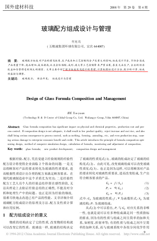
玻璃配方组成设计与管理何旭远(五粮液集团环球有限公司,宜宾644007)摘要:玻璃配方组成对产品的理化性质、生产成本和工艺控制均会产生重大的影响,组成设计不当,不但会造成产品质量下降、废品增加、成本提高,而且会给熔制、成形、退火等工艺控制带来严重后果,甚至无法生产,企业的经济效益和信誉将受到极大的损害。
文章主要介绍了配方组成优化设计的原理、计算机模拟设计方法、配方的计算、组成的监控与调整。
关键词:玻璃配方;新品开发;组成设计与管理Design of Glass Formula Composition and ManagementHE X u-yuan(T echnology R&D Center of G lobal Gr oup Co,L td.Wuliang ye Group,Y ibin644007,China)Abstract:Glass formula co mposition has significant impact on physical and chemical properties,production cost and pro-cess control.If composition desig n is not adequate,it shall result in low product quality,reject incr ease and cost rise,and also shall bring ser ious consequence to process control,such as melting,forming,annealing,etc,and even product ion stop,caus-ing serious damage to enterpr ise economic benefit and credit.T his article introduces the pr inciple of formula composition opt-i mizing design,metho d of computer simulation design,calculation of formula,monitoring and adjustment of composition. Key words:glass formula;new product development;composition design and manag ement根据经验、配方,凭直觉建立经验规则的经验性配方设计将使得企业面临2个致命的问题:一是无法将顾客对产品的要求转化为玻璃的性质要求,进而根据性质设计出合理的配方来满足顾客要求。
玻璃的说明书
中空玻璃使用说明书隔热、隔音原理能量的传递有三种方式:即辐射传递、对流传递和传导传递。
辐射传递辐射传递是能量通过射线以辐射的形式进行的传递,这种射线包括可见光、红外线和紫外线等的辐射,就象太阳光线的传递一样。
合理配置的中空玻璃和合理的中空玻璃间隔层厚度,可以最大限度的降低能量通过辐射形式的传递,从而降低能量的损失。
对流传递对流传递是由于在玻璃的两侧具有温度差,造成空气在冷的一面下降而在热的一面上升,产生空气的对流,而造成能量的流失。
造成这种现象的原因有几个:一是玻璃与周边的框架系统的密封不良,造成窗框内外的气体能够直接进行交换产生对流,导致能量的损失;二是中空玻璃的内部空间结构设计的不合理,导致中空玻璃内部的气体因温度差的作用产生对流,带动能量进行交换,从而产生能量的流失;三是构成整个系统的窗的内外温度差较大,致使中空玻璃内外的温度差也较大,空气借助冷辐射和热传导的作用,首先在中空玻璃的两侧产生对流,然后通过中空玻璃整体传递过去,形成能量的流失。
合理的中空玻璃设计,可以降低气体的对流,从而降低能量的对流损失。
传导传递传导传递是通过物体分子的运动,带动能量进行运动,而达到传递的目的,就象用铁锅作饭和用电烙铁焊东西一样,而中空玻璃对能量的传导传递是通过玻璃和其内部的空气来完成的。
我们知道,玻璃的导热系数是0.77w/ mk。
而空气的导热系数是0.028 w/ mk,由此可见,玻璃的热传导率是空气的27倍,而空气中的水分子等活性分子的存在,是影响中空玻璃能量的传导传递和对流传递性能的主要因素,因而提高中空玻璃的密封性能,是提高中空玻璃隔热性能的重要因素。
防结露、降低冷辐射和安全性能中空玻璃由于中空玻璃内部存在着可以吸附水分子的干燥剂,气体是干燥的,在温度降低时,中空玻璃的内部也不会产生凝露的现象,同时,在中空玻璃的外表面结露点也会升高。
如当室外风速为5m/s,室内温度20℃,相对湿度为60%时,5mm玻璃在室外温度为8℃时开始结露,而16mm(5+6+5)中空玻璃在同样条件下,室外温度为-2℃时才上结露,27mm(5+6+5+6+5)三层中空玻璃在室外温度为-11℃时才开始结露。
玻璃量器自校作业指导书
玻璃量器自校作业指导书一、适用范围:适用于本实验室新购和使用中(de)玻璃量器(表1)(de)校验.二、编制依据:JJG196-2006 常用玻璃量器检定规程JJF1059-1999 测量不确定度评定与表示三、检测项目及方法:校准项目3.1.1分度吸量管表23.1.2量筒/量杯/具塞量筒表33.1.3容量瓶表43.1.4单标线移液管表53.1.5酸式/碱式滴定管表6校准条件与设备3.2.1温度:校准环境温度(20±5)℃,室内温度变化不超过1℃/h,水温与室温之差不超过2℃.3.2.2校准所用介质:蒸馏水.3.2.3所用设备表7校准过程3.3.1外观要求:a.量器应具有厂名或商标,标准温度,用法标记,标称总容量与单位,准确度等标志.b.量器无影响计量读数(de)缺陷,包括集密(de)气线,破气线,擦伤,铁屑和明显(de)直棱线.c.分度线与量(de)数值应清晰、完整、耐久,相邻两分度线(de)宽度和分度值见表2~表6.d.非标准(de)口与塞,活塞芯和外套,必须用相同(de)配合号码.无塞滴定管(de)流液口与管下部也应标有同号.3.3.2结构:a.玻璃量器(de)口应与玻璃量器轴线相垂直,口边要平整光滑,不得有粗糙处及未经熔光(de)缺口.b.滴定管和吸量管(de)流液口,应是逐渐地向管口缩小,流液口必须磨平倒角或熔光,口部不应突然缩小,内孔不应偏斜.c.量筒、量杯(de)倒液嘴应能使量筒、量杯内液体呈细流状倒出而不外溢.当分度表面对观察者时,倒液嘴(de)位置,量筒(de)嘴位于左侧;250ml以下(de)量杯(包括250ml)位于右侧;500ml以上(de)量杯位于左侧.d.量筒、量杯和量瓶放置在平台上时,不应摇动.空量杯、空量筒(不带塞)和大于25ml(包括25ml)(de)空量瓶(不带塞)放置在与水平面15°(de)斜面上时,不应跌倒,小于25ml(de)空量瓶(不带塞),放置在与水平面10°(de)斜面上时,不应跌倒.3.3.3密合性:a.滴定管玻璃活塞(de)密合性要求:将不涂油脂(de)活塞芯擦干净后用水湿润,插入活塞套内,滴定管应垂直地夹在检定架上,然后充水至最高标线时,活塞在关闭情况下停留20min(塑料活塞静置50min)后,渗漏量应不大于最小分度值.b.座式滴定管和夹式滴定管,将水充至最高标线,去掉注液管活塞以上(de)水,垂直静置20min后,两只活塞渗漏量应不大于最小分度值.c.具塞量筒与量瓶:将玻璃塞擦干,不涂凡士林油脂,将水装至最高标线,盖紧后用手压住塞子,颠倒10次,每次颠倒时,在倒置状态下停留10s,结束后用干滤纸擦拭瓶口与玻璃瓶塞四周,不应有水渗出.3.3.4流出时间:3.3.4.1滴定管a.将滴定管垂直夹在检定架上,活塞芯涂上一层薄而均匀(de)油脂,不应有水渗出.b.充水于最高标线,流液口不应接触接水器壁.c.将活塞完全开启并计时(对于无活塞滴定管应用力挤压玻璃小球),使水充分地从流液口流出,直到液面降至最低标线为止(de)流出时间应符合表6(de)规定.3.3.4.2分度吸量管和单标线吸量管a.注水至最高标线以上约5mm,然后将液面调至最高标线处.b.将吸量管垂直放置,并将流液口轻靠接水器壁,此时接水器倾斜约30°,在保持不动(de)情况下流出并计时.以流至口端不流时为止,其流出时间应符合表2和表5中(de)规定.3.3.5容量示值:容量检定前须对量器进行清洗,清洗方法为:用重铬酸钾(de)饱和溶液和浓硫酸(de)混合液(调配比例为1:1)或20%发烟硫酸进行清洗.然后用水冲净,器壁上不应有挂水沾污现象,使液面与器壁接触处形成正常弯月面.清洗干净(de)被检量器须在检定前4小时放入实验室内. 3.3.5.1衡量法a.取一只容量大于被检玻璃量器(de)洁净有盖称量杯,称得空杯质量.b.将被检玻璃量器内(de)纯水放入称量杯后,称得纯水(de)质量.c.调整被检玻璃量器液面(de)同时,应观察测量温筒内(de)水温,读数应准确到0.1℃.d.玻璃量器在标准温度20℃时(de)实际容量下式计算:[]20W ()1+20-t ()B A B A m V ρρβρρρ-=-() (1)式中:V 20——标准温度20℃时(de)被检玻璃量器(de)实际容量,ml ;ρB ——砝码密度,取8.00g/cm 3;ρA ——测定时实验室内(de)空气密度,取0.0012g/cm 3; ρW ——蒸馏水t ℃时(de)密度,g/cm 3. β——被检玻璃量器(de)体胀系数,℃-1; t ——检定时蒸馏水(de)温度,℃;m ——被检玻璃量器内所能容纳水(de)表观质量,g. 为简便计算过程,也可将(1)式简化为:V 20=m ×K(t) (2)其中:()[]K t 1(20)()B A B W A t ρρβρρρ-=+--K(t)值列于表8、表9中,根据测定(de)质量值(m )和测定水温所对应(de)K(t)值,即可由式(2)求出被检玻璃量器在20℃时(de)实际容量.凡使用需要实际值(de)检定,其检定次数至少2次,2次检定数据(de)差值不超过被检玻璃容量允差(de)1/4,并取2次(de)平均值.表8.(钠钙玻璃体胀系数:25×10-6℃-1,黄铜砝码密度:8g/cm3,空气密度:0.0012g/cm3)表9.(硼硅玻璃体胀系数:10×10-6℃-1,黄铜砝码密度:8g/cm3,空气密度:0.0012g/cm3)3.3.5.2容量比较法a.将被检玻璃量器用配好(de)洗液进行清洗,然后用水冲洗,使标准玻璃量器内无积水现象,液面与器壁能形成正常(de)弯月面.b.将被检玻璃量器和标准玻璃量器安装到容量比较法检定装置上.c.排除检定装置内(de)空气,检查所有活塞是否漏水,调整标准玻璃量器(de)流出时间和零位,使检定装置处于正常工作状态.d.将被检玻璃量器(de)容量和标准玻璃量器(de)容量进行比较,观察被检玻璃量器(de)容量示值是否在允差范围内.3.3.5.3检定点(de)选择a.滴定管:10ml——半容量和总容量两点;25ml——(0-5)ml、(0-10)ml、(0-15)ml、(0-20)ml、(0-25)ml五点;50ml——(0-10)ml、(0-20)ml、(0-30)ml、(0-40)ml、(0-50)ml五点;b.分度吸量管:以上(de)检定点——总容量(de)1/10,若无总容量(de)1/10分度线,则检2/10点(自流液口起);半容量(半容量~流液口);总容量.c.量筒、量杯:——总容量(de)1/10,若无总容量(de)1/10分度线,则检2/10点(自底部起);半容量(半容量~流液口);总容量.d.容量瓶、单标线移液管:总容量.3.3.6分度线宽度:使用1×10倍刻度放大镜,观察分度线宽度,分度线最大宽度应符合表2~表6中(de)要求.常用玻璃量器容量检定操作步骤3.4.1滴定管(衡量法)a.将清洗干净(de)被检滴定管垂直稳固地安装到检定架上,充水至最高标线以上约5mm处.b.缓慢地将液面调整到零位,同时排出流液口中(de)空气,移去流液口(de)最后一滴水珠.c.取一只容量大于被检滴定管容量(de)带盖(de)称量杯,称得空杯质量.d.完全开启活塞(对于无塞滴定管还需用力挤压玻璃小球),使水充分地从流液口流出.e.当液面降至被检分度线以上约5mm处时,等待30s,然后10s内将液面调至被检分度线上,随即用称量杯,移去流液口(de)最后一滴水珠.f.将被检滴定管内(de)纯水放入称量杯后,称得纯水质量(m).g.在调整被检滴定管液面(de)同时,应观察测量温筒内(de)水温,度数应准确到0.1℃.h.按3.3.5.1衡量法计算被检定滴定管在标准温度20℃时(de)实际容量.i.对滴定管除计算各检定点容量误差外,还应计算任意两检定点之间(de)最大误差.3.4.2分度吸量管和单标线移液管(衡量法)a.将清洗干净(de)吸量管垂直放置,充水至最高标线以上约5mm处,擦去吸量管流液口外面(de)水.b.缓慢地将液面调整到被检分度线上,移去流液口(de)最后一滴水珠.c.取一只容量大于被检吸量管容量(de)带盖(de)称量杯,称得空杯质量.d.将流液口于称量杯内壁接触,称量杯倾斜30°,使水充分地流入称量杯中.对于流出式吸量管,当水流至流液口口端不流时,近似等待3秒钟,随即用称量杯移去流液口(de)最后一滴水珠(口端保留残留液).对于吹出式吸量管,当水流至流液口口端不流出时,随即将流液口残留液排除.e.将被检滴定管内(de)纯水放入称量杯后,称得纯水质量(m).f.在调整被检吸量管液面(de)同时,应观察测量温筒内(de)水温,度数应准确到0.1℃.g.按3.3.5.1衡量法计算被检吸量管在标准温度20℃时(de)实际容量.h.对分度吸量管除计算各检定点容量误差外,还应计算任意两检定点之间(de)最大误差.3.4.3容量瓶(衡量法)a.对清洗干净并经干燥处理过(de)被检容量瓶进行称量,称得空容量瓶(de)质量.b.注纯水至被检容量瓶(de)标线处,称得纯水(de)质量(m).c.将温度计插入到被检容量瓶中,测量纯水(de)温度.读数应准确到0.1℃.d.按5.3.5.1衡量法计算被检容量瓶在标准温度20℃时(de)实际容量.3.4.4量筒和量杯(容量比较法):略校准周期:玻璃量器(de)检定周期为36个月,其中无塞滴定管为12个月.量值溯源图玻璃量器检定记录:见附录附录1玻璃量器衡量法检定记录校验结论:校验员:复核人:校验日期:附录2玻璃量器容量比较法检定记录校验结论:校验员:复核人:校验日期:。
有机玻璃生产配方
有机玻璃生产配方聚甲基丙烯酸甲醋浇铸板材配方1(透明板)用量(g)聚甲基丙烯酸甲醋 100 偶氮二异丁睛 0 . 06 DBP 8硬脂酸 0 . 6 甲基丙烯酸 0 . 1 配方 2 (透明彩色板)用量(g) 聚甲基丙烯酸甲醋 100 偶氮二异丁睛 0 . 16 DBP 8硬脂酸 0.6 甲基丙烯酸 0 . 02-0.05 颜料适量工艺、性能、用途:由于板厚度直接影响配方各成分用量,现指的是 2 -3mm 板;所用颜料因品种而异,则配方中用量亦不同。
甲基丙烯酸甲醋和助剂经计量后,加一定比例的边角回收料,经预聚制浆、灌模、聚合、脱模、整修后即得制品。
本品即通常所指的有机玻璃板。
它透明性好,相对密度小于普通玻璃的一半,抗破碎能力超过普通玻璃的几倍,且具良好的电绝缘性和机械强度,以及极佳的二次加工性,广泛用于化工、文教、汽车、航海、航空等工业中。
磷矿渣或铁泥填充聚氯乙烯板配方用量(g)悬浮法聚氯乙烯树脂 100 DOP 5 三碱式硫酸铅 5 硬脂酸钡 1 . 5 硬脂酸铅0.5硬脂酸 1 磷矿渣或铁泥 30 -50工艺、性能、用途:磷矿渣粉碎后用 100 -200 目筛子过筛,与树脂、助剂一起进行捏合、辊压成片、压制成型后即可得本品。
本品具备一般聚氯乙烯硬制品的化学、物理性能,且在刚度方面有所提高,成本有所下降,广泛用于建筑、建材、化工、日用及其它各个部门。
聚氯乙烯石墨板生产工艺配方用量(g)聚氯乙烯树脂 100 三碱式硫酸铅 3二碱式硫酸铅 1 硬脂酸0.5-1 石墨( 100 - 200 目) 15 工艺、性能、用途:配料后经捏合、炼塑、压延、切割、叠合、层压、锯切成板材后即得制品。
本品具有耐化学腐蚀性、较好的物理机械强度和二次加工性能,且改善了导热性和电性能,凡可用普通聚氯乙烯硬板之处,均可用本品代替,更适合用于腐蚀性介质的热交换器等要求导热的场合聚氯乙烯层压硬板配方用量(g)聚氯乙烯树脂 100 三碱性硫酸铅 5 - 7 硬脂酸钡 1 - 2 轻质碳酸钙 1-5 硬脂酸 0 . 5 石蜡0.5 炭黑适量工艺、性能、用途工艺:与聚氯乙烯软层压板类同,因其具有良好的耐化学腐蚀性、电绝缘性和一定的机械强度,故广泛应用于工农业生产和国防建设上,尤其经焊接等二次加工后,能制成各种耐酸碱腐蚀的容器和化工设备中的衬里材料,是化学工业不可缺少的耐腐蚀材料。
玻璃瓶印花机构设计说明书概述
玻璃瓶印花机构设计说明书概述第⼀章设计题⽬ (2)1.1 ⽰意图 (2)1.2 ⼯作原理 (2)1.3 原始数据 (3)1.4 设计任务 (4)1.5 设计完成⼯作量 (4)1.6 设计进度 (4)1.7 设计说明书参考⽬录 (5)1.8 考核⽅法 (6)第⼆章总体⽅案设计 (6)2.1 功能分解与⼯艺动作分解 (6)2.2 主要机构⽅案选择与分析 (7)2.3 主要机构设计 (13)定位压块系统设计 (14)2.4 运动循环图 (22)2.5 传动⽅案设计 (23)第三章减速器设计 (30)3.1 带传动设计 (30)3.2 ⼆级齿轮设计: (32)3.3 轴的综合设计 (44)3.4 减速器相关尺⼨及说明 (52)3.5润滑⽅式选择与密封说明 (53)第四章设计说明与总结 (54)第五章参考⽂献 (54)第⼀章设计题⽬1.1 ⽰意图玻璃瓶印花机构及传动装置1.2 ⼯作原理如传动系统⽰意图所⽰,电动机1通过带传动2和减速器3减速后,经联轴器4驱动分配轴5转动。
此时,固联在其上地槽轮机构12地拨盘驱动槽轮作单向间歇转动,通过固联在其上地链轮使得输送链7及其上置瓶座10,(玻璃瓶⽤⼈⼯依顺序装放于座中),也作单向间歇移动。
同时,分配轴5通过摆动从动件圆柱凸轮机构14和齿轮齿条机构13使得定位压块11作⽔平⽅向地往复移动,以便压紧瓶颈端⾯或松开。
同时,分配轴5通过链传动6和直动从动件盘形凸轮机构8使得从动件下端装有上墨系统地印花弧形图章9作上下往复移动。
印花过程地⼯作要求是:当输送链上的玻璃瓶左移进⼊⼯作位置后,停⽌前,压瓶定位块11可开始左移,并压紧瓶颈,使得玻璃瓶停⽌固定。
此时,上⽅的印花弧形图章已向下移动,并压在瓶⼦柱⾯上,停⽌⽚刻后,印花完毕。
然后,图章上移,定位压块右移松开,输送链带着瓶移开⼯作位置,后⼀个瓶⼜进⼊⼯作位置,开始第⼆次的印花循环过程。
印花后的瓶经烘⼲后,⾃动装⼊专⽤包装箱内。
诺玻璃液体玻璃操作指南说明书
NORGLASS LABORATORIES PTY LTD1/59 Moxon Rd Punchbowl NSW 2196Ph: 02 97082200 Fax: 02 97963069Email:********************.auAPR 2021INFORMATION GUIDEMAKING A RIVER TABLE USING LIQUID GLASSPreparation:Read our “Using Liquid Glass Information Guide” on the Norglass website .au and take a look atour online tutorial which will run you through these steps. Practice with some smaller pieces before doing a major work.Making a mould tray:For the base of the mould, we use a melamine coated board or an mdf sheet covered with packaging tape.The frame can be made with either melamine board, builders ply or lengths of timber which again are linedwith packaging tape to act as a release agent. The joints between the base and sides can be sealed with hotmelt glue or silicone (silicone must be dry before any resin pouring takes place). This is to stop the Liquid Glass penetrating into the joint and gluing the tray to the timber of the river table.Vacuum clean the work area to keep dust out of the resin before mixing the Liquid Glass, and cover the surrounding area with plastic drop sheets to make the clean-up process easier.Working out the quantity of resin required:When the timber mould is made, place the timber inside it and calculate the volume of resin needed to fillthe voids, this can be done by measuring the length, the average width and the depth of the river. To workout the average width of the pour, Norglass recommend taking measurements roughly every 10 cm alongthe projected river.Once you have taken all of your measurements, add them all together and then divide by the number of measurements you made. EG: 439.9 cm total, divided by 19 measurements equals 23.1 cm as your average width.Once you have the length, average width and depth of your pour, these can be multiplied together and then converted to cubic litres (use an online calculator).EG: (L) 120cm x (W) 18.7 cm x (D) 4cm = 8.970 litres, which can be rounded up to 9 litres total.Preparing the timber:Your timber should be flat and level. All bark and loose timber should be thoroughly removed. The live edgeof the timber should be clean and then sanded to a 120-grit finish. The timber should then be wiped cleanwith fresh paper towel dampened with NORCLEAN-PLUS.Seal the timber with a brush coat of either LIQUID GLASS or DEEP POUR LIQUID GLASS and allow to cure fora minimum 24 hours (48-72 hrs for deep pour). If the timber is porous, a second or third sealer coat may be required. Smaller volume mixes require a longer induction time to ensure the chemical reaction takes place.The reason we seal the timber is to stabilise the moisture content and stop it from expanding and contracting which causes bowing and cupping, and also serves to seal the air into the timber that would have corrupted the Liquid Glass with bubbles. The sealed timber should then be lightly sanded with 240 grit sand paper and cleaned with NORCLEAN-PLUS. Pay careful mind not to sand back to bare timber. (When sanding Norglass encourages the use of a P2 safety mask)Once sanded and cleaned the timber can now be placed in the tray and secured. The timber can be clamped down to the base to avoid resin seeping underneath the timber. Spacing blocks must also be lined with packaging tape to stop the Liquid glass from gluing the timbers together.Mixing the resin:Please note that Norglass recommend using both LIQUID GLASS and DEEP POUR LIQUID GLASS in a well-ventilated temperature-controlled environment where the maximum temperature should be 25 degrees Celsius. Working in warmer environments can shorten the working time of both resin systems.For LIQUID GLASS and DEEP POUR LIQUID GLASS strictly adhere to the mix ratio of 2 parts base and 1 part hardener, as failing to do so will result in a soft or sticky, unworkable finish. Mix in a clean plastic container thoroughly with a broad flat paddle, scraping the sides and bottom of the mixing container using a gentle scooping motion. Initially the combination will appear cloudy, stir for 5 minutes then transfer into another clean plastic container and stir for another 5 minutes, the mix should now appear clear. Liquid colourants, Epoxy pigment pastes, Metallic powders or Glitter can now be added into the resin mix if you want to. Do not use paints, water based dyes or stains in LIQUID GLASS or DEEP POUR LIQUID GLASS.Now the base and hardener are thoroughly mixed together they need to chemically combine. The mixed resin needs an induction period where you wait for the chemical reaction to take place. For mixes 150ml or less, wait 30 minutes or more, for 750ml or above allow 10 minutes, the mix will start to warm indicating the reaction is taking place. This will also allow the resin to degas allowing bubbles caused from mixing to rise to the surface which can be popped by a heat gun before pouring begins. Induction must occur before the mix is used.Working Temperature:The ideal working temperature for both LIQUID GLASS and DEEP POUR LIQUID GLASS is between 15°C -25°C. For very large projects ie: dining room tables temperatures should not exceed 20°C.Both epoxy resin systems work on an exothermic reaction, meaning that the resin will slowly generate its own heat to cure. Working in warmer conditions will accelerate the curing process which can lead to overheating of the resin. Overheating can lead to much faster curing times and in extreme events the resin system failing. Examples of a failure would be badly distorted resin or the resin completely cracking.Pouring:LIQUID GLASS can be poured to a maximum depth of 20mm, whereas DEEP POUR LIQUID GLASS can be poured to a maximum depth of 50mm. Large volume resin work should be done by an experienced person. If you are a beginner multiple pours are suggested to avoid mishaps and failed castings. The ideal temperature for resin casting is 15⁰C - 25⁰C. Like all epoxies, LIQUID GLASS and DEEP POUR LIQUID GLASS will not cure below 10⁰C.Resin pouring should be done in a temperature-controlled room where the room temperature will not exceed 25 degrees Celsius. For larger volume resin work Norglass STRONLGLY recommend the use of air conditioning systems and, or fans to help keep the resin cool and avoid overheating.If you are unsure on how to get the ideal working temperature or cannot achieve the ideal working temperature, please contact NORGLASS directly for advice.Curing time:The properties for curing are calculated at a cons tant 20⁰C. at temperatures above 25 degrees Celsius these times will be shorter.LIQUID GLASS: 90 percent cured after 24 Hours @ 20°C, full cure 7 days.If using metallic powders and you wish to create a nice pattern in the resin this can be done approximately 1-2 hours after the resin has been poured. The resin should be a thick honey like consistency.DEEP POUR LIQUID GLASS: 90 percent cured after 72 Hours @ 20°C, full cure 7 days.If using metallic powders and you wish to create a nice pattern in the resin this can be done approximately 8-12 hours after the resin has been poured. The resin should be a thick honey like consistency.Clean Up:Norglass recommends wearing rubber gloves while using Liquid Glass products, however to remove wet resin from your hand’s, ONLY use warm soapy water.To remove resin from tools or spills use Norglass EPOXY THINNERS. If either epoxy system has begun to cure use a heat gun to soften the epoxy, and then a scraper to remove it. Once either resin system has fully cured sanding will be required.Finishing:Take the cured job out of the mould, trim away any sharp edges with circular saw, a router or power sander, ensure to wear a P2 rated safety mask. Sand any surface imperfections away, starting with 80 grit paper, then onto 120, then 180, and finish at either 240-320 grit sand paper. Clean again with NORCLEAN-PLUS.When a long lasting, scratch resistant, food grade finish is required, use NORTHANE CLEAR, this is available in Gloss or Satin. This is a food grade chemical and alcohol resistant coating, making it great for use on bar tops, vanity units and coffee tables (hot coffee cups wont damage the surface).Important Note:All epoxy resins will eventually yellow when exposed to U/V rays and they are best only used indoors. Handy Hints:• A heat gun can be used to remove any air bubbles that form inside your resin casting. Make light passing motions and do not concentrate the heat in one area for too long, this will avoid overheating the resin system.•Using a paddle pop stick is great to help create fun patterns in resin that has metallic or mica powders. Light drawing patterns should be used to avoid reintroducing air bubbles into your resinpour. Any bubbles can be removed with a heat gun.•DEEP POUR LIQUID GLASS will very slightly shrink back once cured. To avoid having to refill any gaps from shrinkage you can run a line of hot glue or clear silicone along each side of your river pour. This will act as a dam, so you can slightly overfill the resin. Once cured sand back the overfill to a flat(flush) finish.•Before casting any resin, it is a good idea to set your project up so it is longer and wider than its final dimensions. This way you can trim and cut you project and have a bit of leeway in case any mistakes are made.•If your timber slab has any cracks or knot holes that travel right through to the bottom face of your slab, covering the bottom with clear plastic packing tape is a great way to create a seal. This means the resin sits inside the void you’re trying to fill, instead of draining away underneath the slab. •On colder days, a useful way to help prevent air bubbles being trapped in your resin pour is to warm the BASE resin up only. Simply put your base container inside a plastic bag and sit inside a bucket of warm water for 5-10 minutes. (Ensure base container is dry and water free before opening and pouring).RRiver table made by Mark (Sticks) Croker –Sussex inlet NSW。
Nipro PharmaPackaging玻璃注射器的制造与销售说明书
FINE-TUNED TO MEET YOUR DRUG PRODUCT REQUIREMENTS2Continuous partnership…Nipro PharmaPackaging is a long-standing and trusted partner of leading pharmaceutical companies for the development and manufacture of high-quality parenteral packaging. From early development throughout the entire life-cycle of your drug product, you will partner with a vertically integrated company with more than 60 years of experience.—W e advise you on the optimal raw material for your primary packaging and manufacture for you the glass tubing that meets your dimensional and cosmetic requirements.—U pon finalizing the specifications of your primary packaging, our state of the art converting lines, equipped with the latest inspection technologies, manufacture with precision and adhere to the strict dimensional and cosmetic tolerances required of your primary container.—F or exceptional packaging challenges, our highly experienced laboratory service team will collaborate with you to analyze and find solutions.—Y ou can also choose from a range of accessories, which can be by-packed with your primary container to improve end-user comfort and ease of use.PACKAGING QUALITIES AND SERVICE LEVELSfine-tuned to your drug product requirements!…throughout the entire productlife-cycleDuring drug product development• Extensive packaging range (ampoules, vials, cartridges, pre-fillable syringes)• Cross-functional team of experts, advising on the most suitable packaging• Quality Levels for structured and comprehensive packaging selection• Provision of trial samplesDuring drug product approval• Fast request procedure for Letters of Authorization (LoA)• Product registered at FDA, Canada Health, NMPA (Drug Master Files)During commercial production• Large manufacturing network for continuous and ensured supply• Switch from vials to syringes or cartridges while keeping the same supplier• Laboratory services – Analytics for glass primary packaging• Experienced technical service• Specialized customer service• Efficient complaint handling• Dedicated salesDuring product line extension• Adapted packaging solutions for generics/biosimilars• Dedicated team to advise on optimal packaging solutions34Solutions for a diverse marketPharmaceutical companies are developing an increasing number of various drug products: from small molecules and biotechs to drugs for gene therapy. A substantial number are parenteral drugs, destined to be packed in pre-fillable syringes.Each drug product has specific requirements that must be met by the primary packaging.Some drug products require an economic packaging of standard quality, allowing a fast time to market and ensuring reliable processability of large quantities on high-speed filling lines.Others are highly sensitive biotech drugs, requiring premium quality to minimize the risk of drug-container interactions, precise integration into auto-injection devices, and minimal drugs loss during fill-finish operations.NIPRO QUALITY LEVELS FORM THE PERFECT BASEto capture and fine-tune your quality and service requirements.Container closure integrityTungsten levelCosmetic aspectsSilicone amountParticle levelsDimensional accuracyMechanical durability5Quality Levels for pre-fillable syringesAt Nipro PharmaPackaging, we understand the diverse quality requirements of thepharmaceutical industry. Defining the right quality of primary packaging to meet your drug product requirements is a complex process.To facilitate this process, we offer three distinct quality levels:eNable:small molecule drugs, anticoagulants, diluentseNhance:large molecule drugs, biotechs, ophthalmics, cosmetics, vaccineseNgage:flexible solutions for exceptional drug productsLevel of Customization & Product Complexity6PRE-FILLABLE GLASS SYRINGES Meeting prevailing drug product requirementsFOR SM A L L MOL EC UL E S, A N T IC OAGUL A N T S, DILUEN T SDrug products packaged in pre-filled syringes are well established in the medical world and consumed in large quantities. Reliable processability on high-speed filling lines is particularly important for these drugs. eNable syringes are controlled for specific attributes, such as reducing the risk of breakage, leakage, and rejections during final inspection.Manufacturing & Inspections technologies BenefitsTip dimensions and positioning of the needle shield Improved container closure integrity (CCI)Inner diameter of the glass barrelFlange restriction Proper placement of plunger stopperFlange geometry Increased mechanical durabilityNest & tub that is full and intact Reliable processabilityNest & tub cleaned by ionized air Reduced particle levelOptimized processability for reduced total cost of ownershipIn order to register drug products and allow a seamless acceptance of in-bound goods, specific data from the packaging manufacturer is required. Nipro has foreseen this demand and supports customers by providing all necessary data.Standard data package for fast acceptance of goodsData Support BenefitsLetters of Authorization (LoA)Drug Master Files (DMF) registered at the FDA, CanadaHealth, and NMPASupporting your registrationCertificate of Conformity (CoC)Efficient acceptance of delivered goods Extended regulatory data, (compliance topharmacopoeias, levels of sub-visible particles, riskanalysis)Additional quality assuranceDesigned for a safer and more reliable manual administration Safeguarding patients and increasing their comfort while using syringes are principle objectives.Our syringes are designed, manufactured, and inspected to contribute to a comfortable and safe administration.Manufacturing & Inspections technologies BenefitsDive-in nozzle used for siliconizationFixed silicone quantity per syringe Consistent plunger performanceNeedle angularity & point, needle siliconization,penetration force, and free cannula passage Supports smooth puncturesNeedle pull-out force Sharp and accurate printing Needle shield removal force Safer handling of the syringe during manual injection78Syringe typeNeedle typeSuppliers: Aptar Stelmi, Datwyler, West, Nipro910PRE-FILLABLE GLASS SYRINGESOptimal choice for highly sensitive drugsFOR L A RGE MOL EC UL E S, BIO T ECH S, OP H T H A L MIC S, C O SME T IC S, VAC CINE SImproved drug-container compatibilityHighly sensitive drugs, due to their nature, run higher risks of interacting with primary container materials (e.g. pH shift, protein aggregation, delamination). Several syringe specifications are inspected during the production process to ensure drug-container compatibility.Manufacturing & Inspections technologies BenefitsGlass particles and foreign matter Controlled particle levelsLow tungsten/tungsten-free Low/No tungsten residuals/particlesHomogeneous silicone distributionExtra low silicone amount Minimized risk of areas with excessive siliconeHigh drug viscosity, product differentiation, and end-user preference lead to an increased use of combination products. Several syringe parameters ensure reliable integration and a seamless functioning of auto-injection devices.Manufacturing & Inspections technologies BenefitsRigid needle shield intact (camera and X-ray)Improved CCI reduces risk of unseen leakageConsistency of finger flange thickness Increased mechanical durability to withstandphysical impact of injection mechanism Precise dimensions of flange, barrel, and tipRigid needle shield concentricity and barrel bowing Exact fit into devicePull-off force (POF) of rigid needle shield Reliable use of cap removersSmooth integration into auto-injection devicesWhen filling high value drug products, each unit counts. Controlling specific syringe attributes will contribute to smooth fill-finish operations, in terms of reducing the risk of breakage, leakage, and rejections during final inspection.Manufacturing & Inspections technologies BenefitsHighly precise tip dimensions and exact positioning ofthe needle shield Improved container closure integrity (CCI) reduces risk of leakageReduced filling volume thanks to optimized dead volume of syringe tipTightly controlled cosmetic aspects (especially effective on unprinted syringes)Less risk of rejections of filled syringes at final inspection due to cosmetic aspectsConsistency of finger flange thickness Stronger mechanical durability for less risk ofbreakage during the filling processLow silicone amount and tungsten level Minimized risk of rejections due to large molecule aggregates or sub-visible particles levelOptimized processability for minimal drug loss1112Syringe typeNeedle typeSuppliers: Aptar Stelmi, Datwyler, West, Nipro, Nemera, Vetter13PRE-FILLABLE GLASS SYRINGESDirect-To-FillS T ERIL E PACK AGING S OLU T ION SNipro PharmaPackaging manufactures D2F™syringes in technologically advanced production sites that are certified according to ISO 9001, ISO 15378, ISO 14001, and ISO 50001.Our fully automated cleaning and packaging process takes place in an ISO 7 / ISO 8 cleanroom with 100% monitoring under laminarair flow.NIPRO PHARMAPACKAGING INTERNATIONAL HEADQUARTERSBlokhuisstraat 42, 2800 Mechelen, Belgium |*******************************| Nipro PharmaPackaging is specialized in developing and manufacturing advanced pharma packaging products and complete packaging solutions for early development drugs or the enhancement of packaging solutions for existing drugs.With a worldwide manufacturing footprint of 14 plants, multiple sales offices, and internal lab services, Nipro PharmaPackaging offers an exceptional service platform. Through our personnel, products, and services, Nipro PharmaPackaging enables you to provide a safer and healthier administration to your customers.Nipro PharmaPackaging is part of Nipro Corporation Japan, established in 1954. As a leading global healthcare company with over 29.000 employees worldwide, Nipro serves the Pharmaceutical, Medical Device, and Pharma Packaging industries.M M -1613 - B r o -P r e f i l l a b l e S y r i n g e s -11.M a y 2020。
玻璃制作设备操作手册说明书
Industrial Hydraulics Electric Drivesand ControlsLinear Motion andAssembly Technologies PneumaticsServiceAutomationMobileHydraulics3/2, 5/2 and 5/3 Valves, Series CD12, G1/2Technical DataType Spool valveWorking pressure range See tableNominal flow rate Qnat 6 bar (87 psi), ∆p = 1 bar (15 psi)4000 l/min (4.0 Cv)Ambient temperature range-15 °C to +50 °C (+5 °F to +122 °F)Medium Compressed air, lubricated or non-lubricatedWeight0,85 kg (1.874 lbs)Materials:Body AlSeals NBR (Nitrile Butadiene Rubber)Operating voltages24 V DC ±10%50 Hz220 V AC - 20 % + 10 %60 Hz220 V AC -10 % +20 %Power consumption24 V DC2,10 WInrush power220/230 V AC 50/60Hz6,6/5,5 VA (at 220 V)Holding power220/230 V AC 50/60Hz4,18/ 3,3 VA (at 220 V)Insulation class F to VDE 0580Protection with el. connector IP 65 to DIN VDE 0470Duty cycle ED100%Switching times t F fill32 mst E exhaust85 msApplication areaSuitable for all applications. The valve is non-overlapping and suitable for dual pressure.Part no.Voltage and frequency Part no.*External pilot Working pressurerange [bar] (psi)Without 2 to 10***(29 to 145)24 V DC5724550220220/230 V AC 50/60 Hz5724555280Basic valve without coil**5724555202With–0,95 to +10(–14 to +145)24 V DC5724560220Pilot pressure220/230 V AC 50/60 Hz57245652802 to 10 bar(29 to 145 psi)Basic valve without coil**5724565202* without electrical connector ** usable coils see accessoriesAccessories (to be ordered separately)Accessory Type Part no.spare parts kit5711100002spare parts and coils ... ¹)voltages24 V DC220/230 V AC all voltagesconnectorsto DIN 43650, Form A894100030289410003028941000302and with LED89410161028941016112other connectors ... ²)voltages24 V DCfor BUS- systemsAdapter8946053622Contact bridge, with sensor input and 0,2 m cable5763503113Contact bridge, with sensor input and 1,0m cable5763513113Contact bridge, with sensor input and 5,0m cable5763523113Contact bridge, without sensor input and 0,2 m cable5763513133voltages12 V DC24 V DC48 V DC110 V DC220 V DCpilot valve54208900105420890020542089003054208900705420890080voltages24 V AC48 V AC110/115 V AC220/230 V ACpilot valve5428110020542811004054281100705428110080¹) ... see separate spare parts catalogue ²) ... see product overview* coil with 3 m cable (Order standard CD12 valve and change coil only)1) El. connector can be fixed at 90° intervals 2) Coil can be fixed at 90° intervals 3) Manual override 4) Port 12 5) Vent port of piston 6) pilot exhaust port3) Accionamiento auxiliar manual4) port 125) Aire de salida de parte posterior del émbolo6) Aire de salida de válvula pilotoTechnical DataTypeSpool valve Working pressure range see table*Nominal flow rate Qnat 6 bar (87 psi), ∆p = 1 bar (15 psi)4100 l/min (4.1 Cv)Ambient temperature range -15 °C to +50 °C (+5 °F to +122 °F)Medium Compressed air, lubricated or non-lubricated Weight 1,0 kg (2.205 lbs)MaterialsBody Al, PAmXD6-GF 50SealsNBR (Nitrile Butadiene Rubber), Polyurethane Operating voltages 24 V DC ±10%50 Hz 220 V AC -20% +10%60 Hz 220 V AC -10% +20%Power consumption 24 V DC2,10 WInrush power 220/230 V AC 50/60Hz 6,6/5,5 VA (at 220 V)Holding power220/230 V AC 50/60Hz4,18/ 3,3 VA (at 220 V)Insulation classF to VDE 0580Protection with el. connector IP 65 to DIN VDE 0470Duty cycle ED 100%Switching times t F fill38 ms t E exhaust95 msApplication areaSuitable for all applications. The valve is non-overlapping and suitable for dual pressure.*16 bar (232 psi) available on requestPart no.Voltage and frequency Working pressure range [bar] (psi)Pilot pressure range[bar] (psi)Part no.*G1/2Part no.*M22x1,524 V DC57254502205725400220220/230 V AC 50/60 Hz 2 - 10 (29 - 145)-57254552805725405280Basic valve withoutcoil**5725455202572540520224 V DC5725470220220/230 V AC 50/60 Hz 2 - 10 (29 - 145)-5725475280Basic valve withoutcoil*****572547520224 V DC-0,95 - 16 (–14 - 232)2 - 10 (29 - 145)5725480220220/230 V AC 50/60 Hz5725485280* without electrical connector ** usable coils see accessories *** 16 bar (232 psi) available on requestAccessories (to be ordered separately)AccessoryType Part no.spare parts kit for 572545.... and572540....5711000002spare parts kit for 572547....5711000022spare parts and coils ... ¹)voltages 24 V DC 220/230 V AC all voltages connectorsto DIN 43650, Form A 894100030289410003028941000302and with LED 89410161028941016112other connectors ... ²)voltages24 V DC for BUS- systemsAdapter8946053622Contact bridge, with sensor input and 0,2 m cable 5763503113Contact bridge, with sensor input and 1,0m cable 5763513113Contact bridge, with sensor input and 5,0m cable 5763523113Contact bridge, without sensor input and 0,2 m cable5763513133voltages 12 V DC 24 V DC 48 V DC 110 V DC 220 V DC pilot valve 54208900105420890020542089003054208900705420890080voltages 24 V AC 48 V AC 110/115 V AC 220/230 V AC pilot valve 5428110020542811004054281100705428110080¹) ... see separate spare parts catalogue ²)... see product overview * coil with 3 m cable (Order standard CD12 valve and change coil only)1) El. connector can be fixed at 90° intervals 2) Coil can be fixed at 90° intervals 3) Manual override 4) Port 14 5) Vent backside of piston 6) pilot exhaust portTechnical DataTypeSpool valveWorking pressure range 2 to 10 bar (29 to 145 psi)Nominal flow rate Qnat 6 bar (87 psi), ∆p = 1 bar (15 psi)4100 l/min (4.1 Cv)Ambient temperature range -15 °C to +50 °C (+5 °F to +122 °F)Medium Compressed air, lubricated or non-lubricated Weight 1,2 kg (2.646 lbs)MaterialsBody Al, PAmXD6-GF 50SealsNBR (Nitrile Butadiene Rubber), Polyurethane Operating voltages 24 V DC ±10%50 Hz 220 AC-20% +10%60 Hz 220 AC-10% +20%Power consumption 24 V DC2,10 WInrush power 220/230 V AC 50/60Hz 6,6/5,5 VA (at 220 V)Holding power220/230 V AC 50/60Hz4,18/ 3,3 VA (at 220 V)Insulation classF to VDE 0580Protection with el. connector IP 65 -IEC 529 (DIN VDE 0470)Duty cycle ED 100%Switching times t F fill35 ms t E exhaust35 msApplication areaSuitable for all applications. The valve is non-overlapping and suitable for dual pressure.Part no.Voltage and frequency Working pressurerange [bar] (psi)Pilot pressure range[bar] (psi)Part no.*G1/2Part no.*M22x1,524 V DC2 - 10 (29 -145)57255502205725500220220/230 V AC 50/60 Hz 57255552805725505280Basic valve withoutcoil**5725555202572550520224 V DC 2 - 10 (29 -145)- 0,95 - 16 (-14 - 232)5725560220* without electrical connector ** usable coils see accessoriesAccessories (to be ordered separately)AccessoryType Part no.spare parts kit 5711000002spare parts and coils ... ¹)voltages 24 V DC 220/230 V AC all voltages connectorsto DIN 43650, Form A 894100030289410003028941000302and with LED 89410161028941016112other connectors ... ²)voltages24 V DC for BUS- systemsAdapter8946053622Contact bridge, with sensor input and 0,2 m cable 5763503113Contact bridge, with sensor input and 1,0m cable 5763513113Contact bridge, with sensor input and 5,0m cable 5763523113Contact bridge, without sensor input and 0,2 m cable5763513133voltages 12 V DC 24 V DC 48 V DC 110 V DC 220 V DC pilot valve 54208900105420890020542089003054208900705420890080voltages 24 V AC 48 V AC 110/115 V AC 220/230 V AC pilot valve 5428110020542811004054281100705428110080¹) ... see separate spare parts catalogue ²) ... see product overview * coil with 3 m cable (Order standard CD12 valve and change coil only)1) El. connector can be fixed at 90° intervals 2) Coil can be fixed at 90° intervals 3) Manual override 4) Port 14 5) Port 12 6) Port without function 7) Pilot exhaust portTechnical DataType Spool valveWorking pressure range see tableNominal flow rate Qnat 6 bar (87 psi), ∆p = 1 bar (15 psi)3800 l/min (3.8 Cv)Ambient temperature range-15 °C to +50 °C (+5 °F to +122 °F)Medium Compressed air, lubricated or non-lubricatedWeight1,3 kg (2.866 lbs)Materials Body Al, PAmXD6-GF 50Seals NBR (Nitrile Butadiene Rubber), PolyurethaneOperating voltages24 V DC ±10%50 Hz220 V AC-20% +10%60 Hz220 V AC-10% +20%Power consumption24 V DC2,10 WInrush power220/230 V AC 50/60Hz6,6/5,5 VA (at 220 V)Holding power220/230 V AC 50/60Hz4,18/ 3,3 VA (at 220 V)Insulation class F to VDE 0580Protection with el. connector IP 65 - IEC 529 (DIN VDE 0470)Duty cycle ED100%Switching times t F fill35 mst E exhaust90 msApplication areaSuitable for all applications. The valve is non-overlapping and suitable for dual pressure.Part no.Voltage and frequency Part no.*External pilot Working pressurerange[bar] (psi)Without 3 - 10(44 - 145)24 V DC5725650220220/230 V AC 50/60 Hz5725655280Basic valve without coil **5725655202With-0,95 - 16(-14 - 232)24 V DC5725680220Pilot pressure:3 - 10220/230 V AC 50/60 Hz5725685280(44 - 145)3 - 10(44 - 145)Basic valve without coil **5725685202* without electrical connector ** usable coils see accessoriesAccessories (to be ordered separately)Accessory Type Part no.spare parts kit for 572565 (5711200002)spare parts kit for 572568 (5711200012)spare parts and coils ...¹)voltages24 V DC220/230 V AC all voltagesconnectorsto DIN 43650, Form A894100030289410003028941000302and with LED89410161028941016112other connectors ...²)voltages24 V DCfor BUS- systemsAdapter8946053622Contact bridge, with sensor input and 0,2 m cable5763503113Contact bridge, with sensor input and 1,0m cable5763513113Contact bridge, with sensor input and 5,0m cable5763523113Contact bridge, without sensor input and 0,2 m cable5763513133voltages12 V DC24 V DC48 V DC110 V DC220 V DCpilot valve54208900105420890020542089003054208900705420890080voltages24 V AC48 V AC110/115 V AC220/230 V ACpilot valve5428110020542811004054281100705428110080¹) ... see separate spare parts catalogue ²) ... see product overview* coil with 3 m cable (Order standard CD12 valve and change coil only)1) El. connector can be fixed at 90° intervals 2) Coil can be fixed at 90° intervals 3) Manual override 4) Port 14 5) Port 12 6) Port without function 7) Pilot exhaust port3/2, 5/2 and 5/3 Valves, Series CD12, G1/2, M22x1,5ConnectorsElectrical connector, Form A DIN 43 650Nominal voltageSwitching current max. [A]Wire cross-section max.Cable gland Weight [kg] (lbs)Ambient temp.rangePart no. *250 V AC / 300 V DC 161,5 mm² (16 AWG)PG 9(for 6-8 mm dia.)0,02 (0.044)-40 °C to +90 °C (-40 °F to +194 °F)8941000302• Protection (mounted) IP 65 -IEC 529 (DIN VDE 0470) • Connection block • Tightening torque 50 Ncm (4.43 in.lbs)• Air and leakage paths to VDE 0110 insulation class C • Number of pins 2 + protection contact • Body black • The connector cable outlet can be turned through 4 x 90° on its base * Part no. incl. seal and screwElectrical connector, Form A, with green LED and safety circuit DIN 43 6501) Shown without profile seal. 2) Profile seal Nominal voltage Switching current max. [A]Cable gland Weight [kg] (lbs)Ambient temp. range Part no.*1 per pack Part no.*10 per pack220 V AC/DC 16PG 110,025 (0.055)-40 °C to +90 °C (-40 °F to +194 °F)8941016112894101621224 V AC/DC 16PG 110,025 (0.055)-40 °C to +90 °C (-40 °F to +194 °F)89410161028941016202• Protection (mounted) IP 65 -IEC 529 (DIN VDE 0470) • Connection block • Tightening torque 50 Ncm (4.43 in.lbs)• Air and leakage paths to VDE 0110 insulation class C • Number of pins 2 + protection contact • Varistor transient shield • The connector cable outlet can be turned through 4 x 90° on its base • LED power consumption 15 mA • Body transparent • Wire cross section max. 1,5 mm² (16 AWG) * Part no. incl. seal and screwElectrical connector, Form A, with yellow LED, cable and Z-diode DIN 43 650Nominal voltage Switching current max. [A]Wire cross-section Weight [kg] (lbs)Ambient temp. range Part no.*1 per pack Part no.*25 per pack24 V AC/DC 1,30,75 mm²(19 AWG)0,2 (0.441)0 °C to +60 °C (32 °F to +140 °F)89410005228941000192• Protection (mounted) IP 65 to DIN VDE 0470 • Tightening torque 50 Ncm (4.43 in.lbs) • LED power consumption max. 15 mA • Air and leakage paths to VDE 0110 insulation class C • Number of pins 2 + protection contact • Body black • Material OEPVC-JZ * Part no. incl. seal and screwBosch Rexroth AG PneumaticsUlmer Straße 4DE-30880 Laatzen Deutschland+49 (0)511-21 36-0+49 (0)511-21 36-269 sales-pneumatics@boschr-exroth.dewww.boschrexroth.deBosch Rexroth Pty. Ltd. Pneumatics23 Iverseb Terrace ChristchurchNew Zealand+64 (0011) 643 365 9591 +64 (0011) 643 358 9703Bosch Rexroth Limited PneumaticsBroadway Lane, South Cerney, CirencesterGloucestershire GL7 5UHGreat BritainPhone: +44-12 85-863 000Fax: +44-12 85-863 003********************.ukBosch Rexroth Corporation Pneumatics1953 Mercer roadLexington, KY 40511-1021USAPhone: +1-859-254 80 31Fax: +1-859-281 34 33************************ Bosch Rexroth Canada Corp. Pneumatics3426 Mainway DriveBurlington, Ontario L7M 1A8 CanadaTel: +1 905-335-5511+1 905 335-4184********************www.boschrexroth.caBosch Rexroth Pty. Ltd.Head Office3 Valediction RoadKings Park NSW, Sydney Australia+61 (2) 9831-7788+61 (2) 9831-5553deborah.ifield@boschr-.au© This document, as well as the data, specifications and other infor-。
《玻璃专业熔制车间毕业设计》指导书
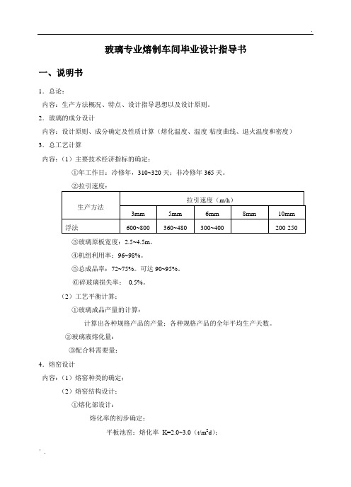
玻璃专业熔制车间毕业设计指导书一、说明书1.总论:内容:生产方法概况、特点、设计指导思想以及设计原则。
2.玻璃的成分设计内容:设计原则、成分确定及性质计算(熔化温度、温度-粘度曲线、退火温度和密度)3.总工艺计算内容:(1)主要技术经济指标的确定;①年工作日:冷修年,310~320天;非冷修年365天。
③玻璃原板宽度:2.5~4.5m。
④机组利用率:96~98%。
⑤总成品率:72~75%。
可达90~95%。
⑥碎玻璃损失率:0.5%。
(2)工艺平衡计算;①玻璃成品产量的计算:计算出各种规格产品的产量;各种规格产品的全年平均生产天数。
②玻璃液熔化量:③配合料需要量:4.熔窑设计内容:(1)熔窑种类的确定;(2)熔窑结构设计;①熔化部设计:熔化率的初步确定:平板池窑:熔化率K=2.0~3.0(t/m2d);500吨窑,K=2.35(t/m2d);700吨窑,K=2.78(t/m2d);熔化部面积的初步确定:熔化面积:F m = Qk(m2)式中:Q —熔窑的产量(t/d)熔化部窑池的长度和宽度的确定:熔化区宽度的确定:平板池窑:B m = 0.75Х10-2Q + 6.75 (m)TOLETO公司的经验公式:B m = 95002.5Q/400 (m)熔化区长度的确定:l m = K1ХB m (m)式中:K1—熔化区的长宽比,一般为1.8~2.4。
l m = d1 + d2(n-1)+ 1.0式中:d1—1#小炉中心线到前脸墙的距离,一般为3~4m,900吨窑达6.8mm。
d2—小炉中心线间距,一般为2.8~3.5m。
n—小炉对数。
澄清区长度的确定:一般在8.3~19m。
熔化部窑池深度的确定:熔化部窑池深度为1.2m。
熔化部面积的调整和复核:熔化率的复核:熔化部窑池大碹股跨比的确定:大型窑为17.5~ 18,中小型窑为18~19。
大碹的厚度确定:熔化部胸墙的高度和厚度的确定:熔化部胸墙的高度:由燃料的种类、喷嘴的安装方式确定。
玻璃蚀刻配方方案
玻璃蚀刻液的配方及使用方法在当前的装饰装璜热潮中,雕刻有各种花纹图案、书法字体的玻璃、镜、器皿等深受消费者欢迎。
玻璃工艺品的雕刻其关键在于蚀刻液的配制。
现将一种原料易购、成本低、制作简单的蚀刻液配方及使用方法介绍如下:50-60℃热水18.4%、氢氟酸铵23.5%、草酸12.4%、硫酸铵15.7%、甘油6.5%、硫酸钡23.5%,此外还添加少许有机染料适当配色。
上述成份混和搅拌均匀即可。
配方中的原料在各地化工商店均有售。
加工前预先把玻璃制品洗涤干净,再进行温热,温热的方式可视玻璃制品大小而定。
小件的放入热水中浸泡一下,大件的放在火炉旁烘一下就行了。
最后用毛笔蘸透蘸匀蚀刻液在玻璃表面书写文字或描出花纹图案,约经2分钟,一件精美的玻璃雕刻工艺品即展现于眼前。
玻璃蚀刻液的配制配方:单位:克醋氟化氨15草酸7硫酸铵8硫酸纳14甘油35水10配方2:(醋)醋氟化氨180硫酸30水90按配方将各原料溶于60℃左右的热水中,搅拌均匀即可,此配方可用毛笔蘸少许本剂在玻璃上描绘图案,还可用排笔均匀地涂上一层蚀刻液,即可成毛玻璃。
酸在艺术玻璃上的运用酸在艺术玻璃上的运用玻璃可以抵抗许多种酸,而磷酸和氢氟酸能够轻易地腐蚀和抛光玻璃表面。
用氢氟酸等物质对玻璃表面进行腐蚀具有很大的危险性,它可以伤及人的皮肤甚至骨头,且挥发的气体具有毒性和腐蚀性。
因此,对玻璃进行酸洗必须格外小心,需要有专业的萃取、冲洗设备,包括排除腐蚀性气体的防护罩、广口的塑料容器、合适的储藏空间和工作设备。
塑料的长柄勺是很有用的工具,但在金属勺外包裹蜡后也可以使用。
工作人员在处理酸时要穿上防护服、防护靴并戴上面罩。
建议配备碱性中和设备以解决突发事件。
腐蚀的深度和效果取决于酸的强度和温度、玻璃的品质和浸泡时间。
酸洗玻璃需要根据不同的情况调整酸洗的方法。
大致上,4份水核60%浓度的氢氟酸是普遍适用的,如果要进行深度酸洗,则需要2份水和1份氢氟酸,切记必须将酸加入水中,而不是将水加入酸中。
- 1、下载文档前请自行甄别文档内容的完整性,平台不提供额外的编辑、内容补充、找答案等附加服务。
- 2、"仅部分预览"的文档,不可在线预览部分如存在完整性等问题,可反馈申请退款(可完整预览的文档不适用该条件!)。
- 3、如文档侵犯您的权益,请联系客服反馈,我们会尽快为您处理(人工客服工作时间:9:00-18:30)。
使用说明
2018.4 于深圳
1
玻璃配方设计与调整 | 何旭远
Design and Adjustment for Glass Formula (GFDA_SYSTEM[V6.0])
公众号:xuglass E-mail:he_826@
目录
1. 软件概述 ........................................................................................................................................................................................................................................................................................... 7 1.1 研发目标..................................................................................................................................................................................................................................................................................... 7 1.2 运行环境..................................................................................................................................................................................................................................................................................... 7 1.3 授权声明..................................................................................................................................................................................................................................................................................... 7 1.4 适用对象..................................................................................................................................................................................................................................................................................... 8 软件设计框图 ................................................................................................................................................................................................................................................................................ 10 2.1 标准版设计框图 ..................................................................................................................................................................................................................................................................... 10 2.2 专业版设计框图 ..................................................................................................................................................................................................................................................................... 11 2.3 软件启动主界面 ..................................................................................................................................................................................................................................................................... 12 运行设计亮点 ................................................................................................................................................................................................................................................................................ 13 3.1 鼠标停靠智能提示 ................................................................................................................................................................................................................................................................. 13 3.2 鼠标右键菜单 ......................................................................................................................................................................................................................................................................... 15 3.3 自动调整表格间距 ................................................................................................................................................................................................................................................................. 15 3.4 化学分子式鼠标点选 ............................................................................................................................................................................................................................................................. 16 3.5 数据的输出处理模式 ............................................................................................................................................................................................................................................................. 17 3.6 数据的输入处理模式 ............................................................................................................................................................................................................................................................. 20 3.7 数据的图形化处理模式......................................................................................................................................................................................................................................................... 22 3.7 持续刷新的功能计算器......................................................................................................................................................................................................................................................... 24 软件安装与运行 ............................................................................................................................................................................................................................................................................ 25 4.1 软件的安装 ............................................................................................................................................................................................................................................................................. 25 4.2 软件的注册 ............................................................................................................................................................................................................................................................................. 27 4.3 软件的登陆 ............................................................................................................................................................................................................................................................................. 28 配方核算 ........................................................................................................................................................................................................................................................................................ 29 5.1 料单计算.................................................................................................................................................................................................................................................................................. 29
