Ford VCM IDS 安装说明
路虎IDS安装说明
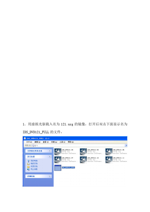
1.用虚拟光驱载入名为121.nrg的镜像,打开后双击下面显示名为IDS_DVD121_FULL的文件,2.开始进行安装设置,选择简体中文语言,点击下一步3.接着弹出下面界面,继续点击下一步4.选择接受许可协议,并打击下一步。
5.选择我已经阅读,点击下一个,如下图所示。
6.选择安装路径,注意磁盘容量,选择好后点击下一个进行下一个设置。
7.安装设置完毕,点击安装,开始安装软件。
8.下面是软件的安装过程,这里要持续一段时间,请耐心等待。
9.安装即将结束,会弹出一个对话框,这里直接点击是。
10.安装完成界面,点击完成,重启电脑。
11. 重启电脑之后,进入软件的安装目录下(这里以F盘为例),找到F:Program Files\JLR\IDS\Runtime目录,找到SysPage文件,下图所示,并双击运行。
12.运行之后会有选择国家的对话框,这里选择中国,并点击打勾按钮,如下图所示。
13.接着选择地区,这里选择Beijing,并点击打勾按钮,如下图所示14.注意这里不能选择其他,要随便选择一个地区,然后打勾。
15.打开软件进入系统功能,点击网络选项,进行网络设置。
17.设置好网络后,选中编译文件和校准文件组合更新,然后点击打勾按钮,如下图所示。
18.进入软件管理向导,这里要上网在线下载,所以要一直接上能上网的网线,直接点击下一步。
19.开始下载,下面是下载过程,不能断开网络。
20.下载完毕后,接着下载校准文件,选择所有车辆,然后点击下一步,这也是要保持网络一直连接。
21.接着会弹出下面界面,点击下一步开始下载,保持网络连接,知道下载结束,软件就安装成功了。
IDS VCM 快速入门指南说明书
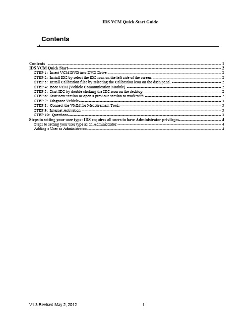
ContentsContents -------------------------------------------------------------------------------------------------------------------------------1 IDS VCM Quick Start----------------------------------------------------------------------------------------------------------------2 STEP 1: Insert VCM DVD into DVD Drive.-----------------------------------------------------------------------------------2 STEP 2: Install IDS by select the IDS icon on the left side of the screen.--------------------------------------------------2 STEP 3: Install Calibration files by selecting the Calibration icon on the dash panel.------------------------------------2 STEP 4: Boot VCM (Vehicle Communication Module).---------------------------------------------------------------------2 STEP 5: Start IDS by double clicking the IDS icon on the desktop---------------------------------------------------------2 STEP 6: Start new session or open a previous session to work with--------------------------------------------------------2 STEP 7: Diagnose Vehicle--------------------------------------------------------------------------------------------------------3 STEP 8: Connect the VMM for Measurement Tools--------------------------------------------------------------------------3 STEP 9: Internet Activation------------------------------------------------------------------------------------------------------3 STEP 10: Questions----------------------------------------------------------------------------------------------------------------3 Steps to setting your user type: IDS requires all users to have Administrator privileges-------------------------------4 Steps to setting your user type as an Administrator:----------------------------------------------------------------------------4 Adding a User as Administrator:--------------------------------------------------------------------------------------------------4IDS VCM Quick StartSTEP 1: Insert VCM DVD into DVD Drive.If you do not see the screen in fig. 1 within 10 seconds, do the following:o Double click My Computer on your desktopo Double click on your DVD driveo Double click the 'Run dpselect.exe' fileSTEP 2: Install IDS by select the IDS icon on the left side of the screen.Hover over any of the icons to see a brief description of the item to be installed. Thedescription will appear on the right side of the screen (fig. 2).After installing IDS, return to dash panel.Dash Panelfig.1 fig.2STEP 3: Install Calibration files by selecting the Calibration icon on the dash panel.STEP 4: Boot VCM (Vehicle Communication Module).Connect VCM to vehicle by connecting the 16-pin DLC cable between the vehicle and VCM.Connect the VCM to the laptop using the Ethernet-USB Host Cable (H-406). Two H-406 cables are included in IDS kit. Both the VCM and VMM use this cable.STEP 5: Start IDS by double clicking the IDS icon on the desktop.STEP 6: Start new session or open a previous session to work withAutomatic Vehicle ID – Select the vehicle icon.Open Previous Session – Select the vehicle icon (above). Next, select the vehicle information screenManual Vehicle ID – Select vehicle icon , then 'Manual Vehicle Entry' from the menu.STEP 7: Diagnose VehicleThe VCM can be used to perform many link-based tests including Datalogger, SelfTest, read CMDTC's, Program Modules, Power Balance, and many Service Functions.The VMM is needed to perform tests requiring measurement tools including Fuel System Test, Oscilloscope, Digital Multi-meter, and Ignition System Test.STEP 8: Connect the VMM for Measurement ToolsConnect the VMM to the laptop using the H-406 (identical to VCM cable)Connect the Battery Cables to vehicle battery.See IDS Hook Up Screens for additional cables needed. These screens will be displayed as needed throughout the tool. See figure 3.STEP 9: Internet ActivationSee IDS Activation Guide for steps to set up your Internet connection. The IDS Activation Guide can be found in the IDS Kit.STEP 10: QuestionsIf you have questions on basic IDS operation, see additional documentation in your IDS Kit.Steps to setting your user type:IDS requires all users to have Administrator privilegesSteps to setting your user type as an Administrator: Click startControl PanelSelect User Accounts (Fig. 1)Create an AccountType a name for the new accountSelect Computer administrator and Create Account (Fig. 2)Adding a User as Administrator: Click StartControl PanelSelect User Accounts (Fig. 1)Click Add (Fig. 3a/b)Type user nameType domain name of computerSelect Other for Administrator (Fig. 4) Fig. 2Fig. 1Fig. 3b Fig. 3aFig.4IDS VCM Quick Start GuideTrademark AcknowledgementsFord is a registered trademark of Ford Motor Company.Copyright InformationIDS VCM Quick Start Guide©2008-2012 Ford Motor Company All rights reservedThe information, specifications and illustrations in this manual are based on the latest information available at the time of printing. Ford Motor Company reserves the right to make changes at any time without notice.。
福克斯定速巡航音控手柄说明书及图片安装

(内容未经允许不得转载盗用,否则予以追究,多谢合作!)图片安装过程.(实际操作比手册其实更简单)工具:梅花螺丝刀(T20),小刀,电烙铁,胶布,定位卡纸,万用表(可选),一字螺丝刀(09款拆面板用),小铁线(用作走线时候引线用) ,CD钥匙(旧款拆CD用),扎带(已配)如果怕麻烦的人,只要配有T20的梅花螺丝刀就可以安装。
拆两个螺丝(螺丝刀是梅花那种),然后用力一点就可以拔下下护板.(已经有手柄的安装CD部分可以pass) (原来有手柄的可以直接从这步开始拆上护板走线)把上护板拉出来,然后接扣上护板按照下护板开孔定位卡纸定位开孔(最后一页有卡纸图),注意要和左边直角对好(我这里卡纸有点偏右了).用电烙铁开孔比电钻方便用小刀割干净毛边(小心割手)旧款福克斯用钥匙把CD机拉出来09款的cd机比较麻烦,要用一字刀先拆开面板,小心刮花(一字刀撬开的位置左右对称)再用梅花螺丝刀(也是T20的)拆开cd的4个螺丝,CD就出来了(09-11款跳过,看下面绿色“接上”符号)(接下)05-08款的cd需要拆下接头用尖器(或者CD钥匙尖的一头)向上顶一下,就可以拆下金属插头塑料固定件继续用尖器拆来固定件的两边卡扣胶片把音响连接线的冷压头从两个胶壳拆下来,然后插到CD后面那个连接插头(线不分正负左右),位置就是图片那里(电路上面是6脚和8脚),务必注意要插到底,然后把两边的扣件锁上,如果接触不良手柄就无法控制音响.可以先连接CD测试一下手柄是否控制到音响.(接上)由于09没有黑色的金属插头塑料固定件,可以直接把金属插针插到6和8脚就可以了.音响控制线和定速巡航的线在拆下CD时候就要布置好, 可以从这个位置穿过去,可以看到有个空位.,用小铁线做引导把巡航线和音响控制线都穿过去,巡航线从CD孔右边这个位置走到保险箱那边拆电箱保险盒,右座下面看到这个旋钮开关,用力向右扭就松开的.电箱有个卡扣位置,向上提就能把保险箱拉出来.拆下最左面的插线头.先把插头红色底座卡扣脱下来把巡航线连接到图上圈的位置,也就是两根黑色的线,要注意把冷压头顶到底务必接触到脚.电路图的位置是10和18两个脚.(线不分正负左右). 冷压头按照图片的方向插进去哦。
VCM II

福特VCM II检测设备
福特VCM II –最新款的FORD,MAZADA,林肯检测设备, 新款的没
有路虎和捷豹的功能。
VCM2 是新型的福特诊断工具。
他通过IDS软
件来进行诊断。
VCM2 通过OBD2接口连接到车辆上,通过USB线或者无线网络连接到电脑上。
2013年以后,一些新款福特车必须通过VCM2来进行诊断。
硬件分有线和无线2个版本,目前昌道科技提供的基本版本有线诊断的含1年在线升级的费用。
下面图片中间的黑色长杆行的那个叫CFR(Customer Flight Recorder) 行车记录仪–这个是选配的。
包含设备:
VCM2接头
OBD2线
USB线
无线适配器
CFR能够支持VCM2从车辆里面检测和记录动态数据流。
可选配。
这为技术人员诊断间歇性的问题提供了有力帮助。
适用于福特,林肯,水星和马自达。
可选配件:
CFR全新或者翻新dell ATG 或者D系列电脑,全新或者翻新松下笔记本
IDS软件服务
电脑安装&软件安装
“ VCM II”相关信息由深圳市昌道科技有限公司编辑提供,转载请注明,谢谢。
德克德车载存储系统安装指南说明书

Watch short installation videos at /video | Register your system at /warrantyInstallation Instructions:MT5 / MT7TOOLS REQUIREDTOYOTA TACOMA5'1” BED LENGTHMT5 2005-2018 / MT7 2019-CURRENTVERSION 1.1 | 208.806.0251• Adjustable wrench (that opens to about 1”)• 1/2” open end wrench • #2 Phillips screwdriver, • Short 7/32” hex wrench • 7/16” deep socket • 3/8” socket• Electric drill • 9/64" drill bit • 1/4” drill bit • 5/16" drill bit • Drill stop • T40 Torx DriverCONTENTSDECKED carton LEFT deck half - 1RIGHT deck half - 1Center vert - 1Cabside vert - 1Drawer - 2Left ammo can - 1Right ammo can - 1Left stud - 1Right stud - 1Ammo can lid - 2C-channel - 2Ruler - 1Hardware box - 1Bottle opener - 1Torsion brace - 1Hardware box - unbagged components(inside DECKED carton):Shims - 4Weather strips - 2HARDWARE box - bagged componentsPREP-MT5 or MT7 - 1S1 - 1S2 - 1N1 - 1J4 - 2DRAWER 1 - 1DRAWER 2 - 1WHEELS - 1FINAL MID - 1PREP-EXTRA - 1MS WASHERS - 1(MT7 ONLY) TACOMA TD - 1▼ HEY! TORQUE BOY: READ BEFORE YOU INSTALL DECKED ▼1. DON’T be an idiot read the instructions.2. DON'T over tighten bolts, get em' hand-tight.3. DON'T use power tools.4.I f you don't follow directions and do use power tools:1). Set clutch at a very low setting. 2). If you blow it, see NOTE.*NOTE* T wo extra threaded inserts are included in BAG PREP-EXTRA . That’s all you get. The inserts will replace anystripped inserts in the tailgate ammo cans, but NOT THE CENTER VERT, so hand tighten until snug only! You can also screw the inserts back in if dislocated. There is a straight screwdriver slot on the underside of the insert.5. Start all bolts with fingers to avoid cross-threading6. DON'T over tighten J-hooks during installation. Make 'em good and snug enough to keep the system from moving in the bed.7. Nice job if you’re still reading .Prevent abusive, expletitive-filled language, watch our detailed installation videoor give us a call. We’re happy to help!208.806.0251 | /INSTALLVIDEOPREP BED: SHIMSNOTE: You will need to grab a pal for this step (or have incredibly long and flexible arms).• Remove top rear factory compartment bolt from the passenger side with a T40 Torx Driver. Keep bolt.• L oosely attach passanger side tailgate bracket with factory bolt in top hole. Make sure the tie down opening is angled toward the driver, not the tailgate ; BAG PREP-MT5 or MT7.• Align bracket so it's parallel with vertical edge of compartment. Tighten factory bolt at last!• Using the bottom hole in bracket as a guide, drill a 5/16" hole with a 1/2" drill stop through compartment and bed wall.• I nstall a 1" bolt through the bracket and bed wall. Install 1" washer and flanged nut and tighten securely ; BAG PREP-MT5 or MT7.• R epeat driver side unless you don't have a driver's side cubby. If not, follow the instructions for driver's side on next page. NOTE: On passenger side ONLY, you will need to add a washer; BAG PREP-MT5 or MT7... We know it's strange, trust us.(FOR TACOMAS WITH NO DRIVER SIDE TAILGATE CUBBY)NOTE: Disregard this page if you HAVE a driver's side tailgate cubby.• R eferencing dimensional info in DETAIL A mark hole locations and drill (2) 5/16" holes (with drill stop set at .62").• R eferencing DETAIL A install J-hook mounting bracket as shown with bolts, backing plate and nuts. Tighten bolts securely. BAG PREP-MT7, BAG TACOMA TD.DETAIL A DRIVER'S SIDE ONLYHOLE DRILLINGBOLT INSTALLATIONDRILL STOP.62"7.5" TO BOTTOM OF BED 5.75" FROM REAR OF BEDBOLTPLATEDETAIL AASSEMBLY: CENTER VERT + CABSIDE VERT NOTE: Perform the next few steps on a flat surface like a garage floor.• Attach center vert to cabside vert with four bolts. Alternate to tighten;BAG S1.ASSEMBLY: LOOSELY ATTACH STUDS (YUP)•LOOSELY attach studs to cabside vert with six bolts; BAG S1.ASSEMBLY: ALIGN & TIGHTEN STUDS (YUP) NOTE: This step ensures the studs are properly located before tightening bolts. It's important.• Place ammo cans to support tailgate end of deck panels.• Lift deck panels on center vert + stud + cabside vert assembly.• Slide studs around L-R until deck panels are seated.• DETAIL A: Loosely secure four bolts to hold decks onto studs; BAG S1.• Now you can securely tighten the bolts that hold the studs to the cabside vert.• Unbolt deck from studs, remove deck panels, save bolts, remove ammo cans and set aside for later assembly.STUD BRACKETTOP HOLECABSIDE BRACKET (GREY)STEP 1STEP 2NOTE: Make sure centerline arrows on cabside vert are aligned with your centerline mark (blue).STEP 3KEEP LOOSETIGHTENTHREE3 1/2"BOLTS3/4" BOLTCAB➡➡CABASSEMBLY: BRACKETS + MOUNTING• STEP 1: Securely attach stud bracket to driver side stud using three 3 1/2" bolts and three flanged nuts; BAG PREP-MT5 or MT7.• STEP 2: Loosely attach cabside bracket to the top hole in stud bracket with 3/4" bolt and flanged nut; BAG PREP-MT5 or MT7. KEEP LOOSE.• Repeat STEP 1 and STEP 2 on passenger side.• STEP 3: While supporting both ends, lift center vert + stud + cabside vert assembly in truck bed.FLANGED NUT➡CABFLANGED NUTSRECOMMENDED TORQUE: For all fasteners - 27 in-lb.INSTALL: CABSIDE BRACKET DRILL • Place driver side cabside bracket flush against truck bed wall, now tighten securely to stud bracket.• While keeping assembly on centerline, drill three 1/4" diameter holes into bed using cabside bracket as a guide (green holes). Make sure to use a drill stop set to 1/2" depth.1/4” DRILL BITDRILL STOP1/2”RECOMMENDED TORQUE:53 in-lb.INSTALL: BACKING PLATENOTE: If your pal left, clank some cans together to get them to come back.• Install three 1" bolts through holes in cabside bracket and pickup bed; BAG PREP-MT5 or MT7.• Play Rock Paper Scissors with your pal. The loser needs to hold the backing plate inside the wheel well and attach three flanged nuts; BAG PREP-MT5 or MT7. Securely tighten.• Repeat passenger side.INSTALL: C-CHANNEL• Loosely place driver side ammo can at tailgate corner of bed. The axles should be on the tailgate side of the truck.•INSTALL: DECK HALVES• Loosely place driver side deck panel on driver side stud, center vert and ammo can.• Shift tailgate ammo can forward, rearward, L-R, as necessary to align with fully seated deck panel.• Loosely assemble:• Five bolts (without washers) through deck panel into center vert; BAG S1.• Four bolts with nylon and rubber washers installed in order shown in DETAIL A through deck panel intostud; BAG S1,BAG MS WASHERS.• Eight bolts with nylon and rubber washers installed in order shown in DETAIL A through deck panel into tailgate ammo can; BAG S1,BAG MS WASHERS.• Tighten all S1 bolts.•Securely tighten driver side C-Channel/ammo can nut and bolt.• Repeat passenger side (make sure you don't forget to securely tighten passenger side C-Channel/ammo canINSTALL: J-HOOKS•Loosely assemble driver side J-hook assembly in order shown through tailgate side hole in ammo can; BAG J4.• Repeat passenger side.DRIVER SIDE AMMO CAN PASSENGER SIDE AMMO CANKEEP LOOSEKEEP LOOSEDRAWERS: BRACKETS + WHEELS • E ach drawer has a left and a right bracket. Bolt brackets into place via bottom two holes in bracket with 3/4"length bolts. Use the 2" length bolt for the upper cabside wall hole in bracket; BAG DRAWER 1.• Install a tube brace in each drawer with two 3/4" length bolts; BAG DRAWER 1, BAG DRAWER 2.DRAWERS: AXLE WHEELS + WEATHERSTRIPS • Slide narrow drawer into driver side drawer cavity. NOTE: It is easier to fully install narrow drawer first.➡FINAL STEPS: TORSION BRACE + BOTTLEOPENER• S lide torsion brace under center vert and tailgate ammo cans.NOTE: If you jumped the gun and tightened the J-hooks when installing, loosen them.• L oosely install:• T wo bolts with nylon washers through the end holes in torsion brace into ammo cans; BAG S1.• T wo bolts with nylon washers through the bottom bottle opener holes and torsion brace into center vert; BAG S1.• Two 1/2" length bolts through upper holes in bottle opener into center vert; BAG FINAL MID.• Align bottle opener to edges of center vert and tighten four bottle opener bolts.• T ighten end bolts into tailgate ammo cans.• F inally.....Tighten the J-hooks! DO NOT OVER TIGHTEN, just make snug. Make sure the gap between the sidewall of the bed and the deck is equal on both sides.9/64” DRILLBITDRILL STOP1/2”FINAL STEPS: AMMO CAN LIDS•DETAIL A: Ammo can lids are driver (marked L) and passenger (marked R) side specific.•DETAIL B: Holding lid in orientation shown, insert tab on tailgate end of ammo can lid and push the cabside end of lid down to secure. Don't be afraid to give'r the Fonzi to close, it's rugged.• Insert lock hole plugs, unless you ordered drawer locks! Install drawer locks now (instructions with locks); BAG FINAL MID.IMPORTANT: Grab your favorite beverage, crack 'er open in the bottle opener and christen this ship! You did it. Immediately post a photo of your significant other, child or canine (in no order of significance) a ppreciating your accomplishment. Add hashtag #DECKEDUSA | @DECKEDUSA .DETAIL A DRIVER SIDE AMMO CAN LID PASSENGER SIDE AMMO CAN LIDDECKED 3-YEAR LIMITED WARRANTY(a.k.a. LEGAL MUMBO JUMBO)DECKED LLC warrants to the original purchaser of this product that the product will be free from manufacturing defects in workmanship and materials for a period of three (3) years from the date of the original purchase. If within three (3) years from the original date of purchase this product fails due to defect in materials or workmanship, DECKED LLC will replace any defective part at its option.The original purchaser must contact the DECKED LLC customer service team and provide a description of the defective part, including digital pictures if requested, with the original purchase documentation as validation of warranty coverage or have previously activated their warranty online.This warranty DOES NOT cover or apply to:• Damage to the product due to misuse, mishandling and abuse.• Products not used in accordance with the manufacturer’s instructions or recommendations.• Product not assembled or installed according to manufacturer’s instructions.• Normal wear and tear.•U ndeclared damage to the system during shipping, acts of God. In addition, consequential damage and incidentaldamages (including lost time) such as damage to persons or property are not covered under this warranty.REGISTER YOUR PRODUCT FOR ANY FUTURE WARRANTY NEEDS. /REGISTER#DECKEDUSA | @DECKEDUSA | #DECKEDUSA | @DECKEDUSA MT5 / MT7 | v.1.1 | Page 21。
___诊断仪安装与操作

___诊断仪安装与操作诊断仪安装___诊断仪是一种用于诊断和检测___发动机故障的工具。
安装该诊断仪可以帮助用户快速并准确地定位和修复发动机故障。
以下是安装___诊断仪的步骤和注意事项:首先,确保已经购买到合适的___诊断仪设备,并确保设备的完整性和正常功能。
接下来,找到合适的安装位置。
一般来说,安装位置应离发动机比较近,便于操作和连接。
在安装位置上安装诊断仪的底座或支架。
确保底座或支架稳固可靠,不会晃动或松动。
将诊断仪设备固定在底座或支架上。
根据设备说明书或指南,确保设备固定牢固。
根据设备的连接线路和接口,将诊断仪连接到发动机的诊断接口上。
确保连接正确,接口紧固稳固。
安装完成后,检查一遍设备的连接是否稳固,确保没有断线或松动的地方。
诊断仪操作安装完成后,下面是一些使用___诊断仪的操作注意事项:开启玉柴诊断仪设备电源。
根据设备说明书或指南,正确操作电源开关。
确认诊断仪设备是否成功连接到发动机。
通过观察屏幕或指示灯,确认设备是否正常工作。
根据诊断仪的菜单,选择相应的诊断功能。
根据故障代码或发动机症状,选择适当的诊断功能进行故障检测。
遵循诊断仪的提示和指引,进行故障检测和诊断。
根据诊断仪显示的信息,定位并修复发动机故障。
在诊断完成后,根据实际情况选择是否清除故障码。
如果发动机问题已被修复,可以清除故障码。
使用完___诊断仪后,及时关闭设备电源,并正确存放设备。
确保设备处于安全状态。
以上是关于___诊断仪的安装与操作的简要概述。
希望这些信息对您有帮助!本文档旨在说明如何正确操作___诊断仪,包括连接步骤、功能介绍和常见问题解决。
连接步骤确保车辆处于停止状态,并拔下车钥匙。
使用诊断仪附带的连接线,将诊断仪连接至车辆的OBD 接口。
确保连接牢固。
打开车辆电源,但不要启动发动机。
功能介绍___诊断仪提供了多项功能,方便用户进行车辆故障诊断和维护操作。
以下是一些常用功能的简要介绍:故障码读取与清除:诊断仪能够读取车辆的故障码,并清除已修复的故障码,以确保发动机正常运行。
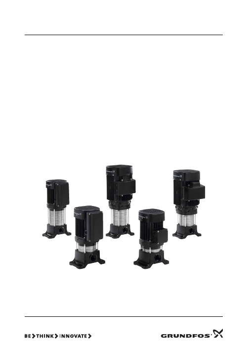
grundfos cmv 安装和使用说明书
GRUNDFOS 说明书CMV安装和使用说明书产品合格声明书2产品合格声明书GB: EC declaration of conformityWe, Grundfos, declare under our sole responsibility that the products CMV, to which this declaration relates, are in conformity with these Council directives on the approximation of the laws of the EC member states:–Machinery Directive (2006/42/EC).Standards used: EN 809:1998 +A1:2009 and EN 60204-1:2006.–Low Voltage Directive (2006/95/EC).Applicable when the rated power is lower than 2.2 kW.Standards used: EN 60335-1:2002 and EN 60335-2-51:2003.–EMC Directive (2004/108/EC).–Ecodesign Directive (2009/125/EC).Electric motors:Commission Regulation No 640/2009.Applies only to three-phase Grundfos motors marked IE2 or IE3. See motor nameplate.Standard used: EN 60034-30:2009.–Ecodesign Directive (2009/125/EC).Water pumps:Commission Regulation No 547/2012.Applies only to water pumps marked with the minimum efficiency index MEI. See pump nameplate.This EC declaration of conformity is only valid when published as part of the Grundfos installation and operating instructions (publication number 97907165 1212).BG: EC декларация за съответствиеНие, фирма Grundfos, заявяваме с пълна отговорност, че продуктите CMV, за които се отнася настоящата декларация, отговарят на следните указания на Съвета за уеднаквяване на правните разпоредби на държавите членки на ЕС:–Директива за машините (2006/42/EC).Приложени стандарти: EN 809:1998 +A1:2009 и EN 60204-1:2006.–Директива за нисковолтови системи (2006/95/EC).Приложим за помпи с номинална мощност по-малка от 2,2 kW. Приложени стандарти: EN 60335-1:2002 и EN 60335-2-51:2003.–Директива за електромагнитна съвместимост (2004/108/EC). –Директива за екодизайн (2009/125/EC).Електродвигатели:Наредба No 640/2009 на Европейската комисия.Отнася се само за трифазни електродвигатели на Grundfos, маркирани с IE2 или IE3. Вижте табелата с данни на двигателя.Приложен стандарт: EN 60034-30:2009.–Директива за екодизайн (2009/125/EC).Водни помпи:Наредба No 547/2012 на Европейската комисия.Отнася се само за водни помпи, маркирани с минималният индекс за ефективност MEI. Вижте табелата с данни на помпата.Тази ЕС декларация за съответствие е валидна само когато е публикувана като част от инструкциите за монтаж и експлоатация на Grundfos (номер на публикацията 97907165 1212).CZ: ES prohlášení o shod ěMy firma Grundfos prohlašujeme na svou plnou odpov ědnost, že výrobek CMV, na n ějž se toto prohlášení vztahuje, je v souladu s ustanoveními sm ěrnice Rady pro sblížení právních p ředpis ů členských stát ů Evropského spole čenství v oblastech:–Sm ěrnice pro strojní za řízení (2006/42/ES).Použité normy: EN 809:1998 +A1:2009 a EN 60204-1:2006.–Sm ěrnice pro nízkonap ět’ové aplikace (2006/95/ES).Je možno použít, pokud jmenovitý výkon je menší než 2,2 kW.Použité normy: EN 60335-1:2002 a EN 60335-2-51:2003.–Sm ěrnice pro elektromagnetickou kompatibilitu (EMC)(2004/108/ES).–Sm ěrnice o ekodesignu (2009/125/ES).Elektrické motory:Na řízení Komise č. 640/2009.Platí pouze pro t řífázové motory Grundfos ozna čené IE2 nebo IE3. Viz typový štítek motoru.Použitá norma: EN 60034-30:2009.–Sm ěrnice o ekodesignu (2009/125/ES).Vodní čerpadla:Na řízení Komise č. 547/2012.Vztahuje se pouze na vodní čerpadla ozna čená minimální účinností index MEI. Viz typový štítek čerpadla.Toto ES prohlášení o shod ě je platné pouze tehdy, pokud jezve řejn ěno jako sou část instala čních a provozních návod ů Grundfos (publikace číslo 97907165 1212).DK: EF-overensstemmelseserklæringVi, Grundfos, erklærer under ansvar at produkterne CMV som denne erklæring omhandler, er i overensstemmelse med disse af Rådets direktiver om indbyrdes tilnærmelse til EF-medlemsstaternes lovgivning:–Maskindirektivet (2006/42/EF).Anvendte standarder: EN 809:1998 +A1:2009 og EN 60204-1:2006.–Lavspændingsdirektivet (2006/95/EF).Gælder når mærkeeffekten er lavere end 2,2 kW.Anvendte standarder: EN 60335-1:2002 og EN 60335-2-51:2003.–EMC-direktivet (2004/108/EF).–Ecodesigndirektivet (2009/125/EF).Elektriske motorer:Kommissionens forordning nr. 640/2009.Gælder kun 3-fasede Grundfos-motorer der er mærket IE2 eller IE3. Se motorens typeskilt.Anvendt standard: EN 60034-30:2009.–Ecodesigndirektivet (2009/125/EF).Vandpumper:Kommissionens forordning nr. 547/2012.Gælder kun vandpumper der er mærket medmindsteeffektivitetsindekset MEI. Se pumpens typeskilt.Denne EF-overensstemmelseserklæring er kun gyldig når denpubliceres som en del af Grundfos-monterings- og driftsinstruktionen (publikationsnummer 97907165 1212).产品合格声明书3DE: EG-KonformitätserklärungWir, Grundfos, erklären in alleiniger Verantwortung, dass die Produkte CMV, auf die sich diese Erklärung bezieht, mit den folgenden Richtlinien des Rates zur Angleichung der Rechts-vorschriften der EU-Mitgliedsstaaten übereinstimmen:–Maschinenrichtlinie (2006/42/EG).Normen, die verwendet wurden: EN 809:1998 +A1:2009 und EN 60204-1:2006.–Niederspannungsrichtlinie (2006/95/EG).Nur anwendbar für Nennleistungen kleiner als 2,2 kW.Normen, die verwendet wurden: EN 60335-1:2002 und EN 60335-2-51:2003.–EMV-Richtlinie (2004/108/EG).–ErP-Richtlinie (2009/125/EG).Elektromotoren:Verordnung der Europäischen Kommission Nr. 640/2009.Gilt nur für dreiphasige Motoren von Grundfos mit derKennzeichnung IE2 bzw. IE3. Siehe Typenschild des Motors.Norm, die verwendet wurde: EN 60034-30:2009.–ErP-Richtlinie (2009/125/EG).Wasserpumpen:Verordnung der Europäischen Kommission Nr. 547/2012.Gilt nur für Pumpen, für die der Mindesteffizienzindex (MEI) anzugeben ist. Siehe Typenschild der Pumpe.Diese EG-Konformitätserklärung gilt nur, wenn sie in Verbindung mit der Grundfos Montage- und Betriebsanleitung (Veröffentlichungs-nummer 97907165 1212) veröffentlicht wird.GR: ∆ήλωση συμμόρφωσης ECΕμείς, η Grundfos, δηλώνουμε με αποκλειστικά δική μας ευθύνη ότιταπροϊόντα CMV στα οποία αναφέρεται η παρούσα δήλωση, συμμορφώνονται με τις εξής Οδηγίες του Συμβουλίου περί προσέγγισης των νομοθεσιών των κρατών μελών της ΕΕ:–Οδηγία για μηχανήματα (2006/42/EC).Πρότυπα που χρησιμοποιήθηκαν: EN 809:1998 +A1:2009 και EN 60204-1:2006.–Οδηγία χαμηλής τάσης (2006/95/EC).Ισχύει για ονομαστική ισχύ μικρότερη από 2,2 kW.Πρότυπα που χρησιμοποιήθηκαν: EN 60335-1:2002 και EN 60335-2-51:2003.–Οδηγία Ηλεκτρομαγνητικής Συμβατότητας (EMC) (2004/108/EC).–Οδηγία Οικολογικού Σχεδιασμού (2009/125/ΕC).Ηλεκτρικοί κινητήρες:Ρύθμιση πρώτης εκκίνησης Νο 640/2009.Ισχύει μόνο σε τριφασικούς κινητήρες της Grundfos με σήμανση ΙΕ2ή ΙΕ3. Βλέπε πινακίδα κινητήρα.Πρότυπο που χρησιμοποιήθηκε: EN 60034-30:2009.–Οδηγία Οικολογικού Σχεδιασμού (2009/125/EC).Αντλίες νερού:Ρύθμιση πρώτης εκκίνησης Νο 547/2012.Ισχύει μόνο για αντλίες νερού που φέρουν τον ελάχιστο δείκτη απόδοσης ΜΕΙ. Βλέπε πινακίδα αντλίας.Αυτή η δήλωση συμμόρφωσης EC ισχύει μόνον όταν συνοδεύει τις οδηγίες εγκατάστασης και λειτουργίας της Grundfos (κωδικός εντύπου 97907165 1212).ES: Declaración CE de conformidadNosotros, Grundfos, declaramos bajo nuestra entera responsabilidad que los productos CMV, a los cuales se refiere esta declaración, están conformes con las Directivas del Consejo en la aproximación de las leyes de las Estados Miembros del EM:–Directiva de Maquinaria (2006/42/CE).Normas aplicadas: EN 809:1998 +A1:2009 y EN 60204-1:2006.–Directiva de Baja Tensión (2006/95/CE).Aplicable cuando el índice de potencia es inferior a 2,2 kW.Normas aplicadas: EN 60335-1:2002 y EN 60335-2-51:2003.–Directiva EMC (2004/108/CE).–Directiva sobre diseño ecológico (2009/125/CE).Motores eléctricos:Reglamento de la Comisión Nº 640/2009.Válido sólo para motores trifásicos Grundfos pertenecientes a las categorías IE2 e IE3. Véase la placa de características del motor.Norma aplicada: EN 60034-30:2009.–Directiva sobre diseño ecológico (2009/125/CE).Bombas de agua:Reglamento de la Comisión Nº 547/2012.Aplicable únicamente a las bombas de agua marcadas con el índice de eficiencia mínima (IEM). Véase la placa de características de la bomba.Esta declaración CE de conformidad sólo es válida cuando se publique como parte de las instrucciones de instalación yfuncionamiento de Grundfos (número de publicación 97907165 1212).FR: Déclaration de conformité CENous, Grundfos, déclarons sous notre seule responsabilité,que les produits CMV, auxquels se réfère cette déclaration, sont conformes aux Directives du Conseil concernant le rapprochement des législations des Etats membres CE relatives aux normes énoncées ci-dessous:–Directive Machines (2006/42/CE).Normes utilisées: EN 809:1998 +A1:2009 et EN 60204-1:2006.–Directive Basse Tension (2006/95/CE).Applicable lorsque la puissance nominale est inférieure à 2,2 kW.Normes utilisées: EN 60335-1:2002 et EN 60335-2-51:2003.–Directive Compatibilité Electromagnétique CEM (2004/108/CE).–Directive sur l'éco-conception (2009/125/CE).Moteurs électriques:Règlement de la Commission Nº 640/2009.S'applique uniquement aux moteurs triphasés Grundfos marqués IE2 ou IE3. Voir plaque signalétique du moteur.Norme utilisée: EN 60034-30:2009.–Directive sur l'éco-conception (2009/125/CE).Pompes à eau:Règlement de la Commission Nº 547/2012.S'applique uniquement aux pompes à eau marquées de l'indice de performance minimum IEM. Voir plaque signalétique de la pompe.Cette déclaration de conformité CE est uniquement valide lors de sa publication dans la notice d'installation et de fonctionnement Grundfos (numéro de publication 97907165 1212).产品合格声明书4IT: Dichiarazione di conformità CEGrundfos dichiara sotto la sua esclusiva responsabilità che i prodotti CMV, ai quali si riferisce questa dichiarazione, sono conformi alle seguenti direttive del Consiglio riguardanti il riavvicinamento delle legislazioni degli Stati membri CE:–Direttiva Macchine (2006/42/CE).Norme applicate: EN 809:1998 +A1:2009 e EN 60204-1:2006.–Direttiva Bassa Tensione (2006/95/CE).E' applicabile quando la potenza nominale è inferiore a 2,2 kW. Norme applicate: EN 60335-1:2002 e EN 60335-2-51:2003.–Direttiva EMC (2004/108/CE).–Direttiva Ecodesign (2009/125/CE).Motori elettrici:Regolamento CE n. 640/2009.Applicabile solo ai motori trifase Grundfos contrassegnati IE2 o IE3. Vedere la targhetta di identificazione del motore.Norma applicata: EN 60034-30:2009.–Direttiva Ecodesign (2009/125/CE).Pompe per acqua:Regolamento CE n. 547/2012.Applicabile solo a pompe per acqua con l'indice di efficienza minimo MEI. Vedere la targhetta di identificazione della pompa.Questa dichiarazione di conformità CE è valida solo quando pubblicata come parte delle istruzioni di installazione efunzionamento Grundfos (pubblicazione numero 97907165 1212).KZ: EO сəйкестік туралы мəлімдемеБіз, Grundfos компаниясы, барлық жауапкершілікпен, осы мəлімдемеге қатысты болатын CMV бұйымдары ЕО мүшеелдерінің заң шығарушы жарлықтарын үндестіру туралы мына Еуроодақ Кеңесінің жарлықтарына сəйкес келетіндігін мəлімдейміз:–Механикалық құрылғылар (2006/42/EC).Қолданылған стандарттар: EN 809:1998 +A1:2009 жəне EN 60204-1:2006.–Төмен Кернеулі Жабдық (2006/95/EC).Номиналды қуаты 2,2 кВт-тан аз болғанда қолдануға жарамды.Қолданылған стандарттар: EN 60335-1:2002 жəне EN 60335-2-51:2003.–Электр магнитті үйлесімділік (2004/108/EC).–Қоршаған ортаны қорғауға арналған нұсқау (2009/125/EC).Электр қозғалтқыш:Еуропалық комиссия регламенті 640/2009.IE2 немесе IE3 белгіленген үш фазалы Grundfos моторларына ғана қолданылады. Қозғалтқыштың техникалық деректері бар фирмалық тақташаны қараңыз.Қолданылған стандарт: EN 60034-30:2009.–Қоршаған ортаны қорғауға арналған нұсқау (2009/125/EC).Су сорғылар:Еуропалық комиссия регламенті 547/2012.Тек минималды тиімділік көрсіткішіпен МТК белгіленген су сорғыларына арналған. Сорғыдағы фирмалық тақтайшаны қараңыз.Бұл EO сəйкестік туралы мəлімдеме тек ғана Грундфос компаниясының орнату жəне пайдалану нұсқасының бөлімі ретінде жарамды (баспаға шыққан нөмірі 97907165 1212).HU: EK megfelel őségi nyilatkozatMi, a Grundfos, egyedüli felel ősséggel kijelentjük, hogy a CMV termékek, amelyekre jelen nyilatkozik vonatkozik, megfelelnek az Európai Unió tagállamainak jogi irányelveit összehangoló tanács alábbi el őírásainak:–Gépek (2006/42/EK).Alkalmazott szabványok: EN 809:1998 +A1:2009 és EN 60204-1:2006.–Kisfeszültség ű Direktíva (2006/95/EK).Akkor alkalmazható, amikor a névleges teljesítmény kisebb mint 2,2kW.Alkalmazott szabványok: EN 60335-1:2002 és EN 60335-2-51:2003.–EMC Direktíva (2004/108/EK).–Környezetbarát tervezésre vonatkozó irányelv (2009/125/EK).Villamos motorok:Az Európai Bizottság 640/2009. számú rendelete.Csak az IE2 vagy IE3 jelzés ű háromfázisú Grundfos motorokra vonatkozik. Lásd a motor adattábláját.Alkalmazott szabvány: EN 60034-30:2009.–Környezetbarát tervezésre vonatkozó irányelv (2009/125/EK).Víz szivattyúk:Az Európai Bizottság 547/2012. számú rendelete.Csak a MEI minimum hatásfok index-el jelölt víz szivattyúkra vonatkozik. Lásd a szivattyú adattábláján.Ez az EK megfelel őségi nyilatkozat kizárólag akkor érvényes, ha Grundfos telepítési és üzemeltetési utasítás (kiadvány szám 97907165 1212) részeként kerül kiadásra.NL: EC overeenkomstigheidsverklaringWij, Grundfos, verklaren geheel onder eigen verantwoordelijkheid dat de producten CMV waarop deze verklaring betrekking heeft, in overeenstemming zijn met de Richtlijnen van de Raad in zake de onderlinge aanpassing van de wetgeving van de EG Lidstaten betreffende:–Machine Richtlijn (2006/42/EC).Gebruikte normen: EN 809:1998 +A1:2009 en EN 60204-1:2006.–Laagspannings Richtlijn (2006/95/EC).Van toepassing bij nominaal vermogen lager dan 2,2 kW.Gebruikte normen: EN 60335-1:2002 en EN 60335-2-51:2003.–EMC Richtlijn (2004/108/EC).–Ecodesign Richtlijn (2009/125/EC).Elektromotoren:Verordening (EG) Nr. 640/2009 van de Commissie.Geldt alleen voor de driefase elektromotoren van Grundfos, aangeduid met IE2 of IE3. Zie het typeplaatje van de motor.Gebruikte norm: EN 60034-30:2009.–Ecodesign Richtlijn (2009/125/EC).Waterpompen:Verordening (EG) Nr. 547/2012 van de Commissie.Is alleen van toepassing op waterpompen die gekenmerkt worden door de minimale efficiëntie index MEI. Zie het typeplaatje van de pomp.Deze EC overeenkomstigheidsverklaring is alleen geldig wanneer deze gepubliceerd is als onderdeel van de Grundfos installatie- en bedieningsinstructies (publicatienummer 97907165 1212).产品合格声明书5UA: Декларація відповідності ЄСКомпанія Grundfos заявляє про свою виключну відповідальність зате, що продукти CMV, на які поширюється дана декларація, відповідають таким рекомендаціям Ради з уніфікації правових норм країн - членів ЄС:–Механічні прилади (2006/42/ЄС).Стандарти, що застосовувалися: EN 809:1998 +A1:2009 та EN 60204-1:2006.–Низька напруга (2006/95/ЄС).Може застосовуватися при потужності до 2,2 кВт.Стандарти, що застосовувалися: EN 60335-1:2002 та EN 60335-2-51:2003.–Електромагнітна сумісність (2004/108/ЄС).–Директива з екодизайну (2009/125/ЄС).Електродвигуни:Регламент Комісії № 640/2009.Застосовується тільки до трифазних електродвигунів Grundfos, позначених IE2 або IE3. Дивіться паспортну табличку електродвигуна.Стандарти, що застосовувалися: EN 60034-30:2009.–Директива з екодизайну (2009/125/ЄС).Насоси для води:Регламент Комісії № 547/2012.Стосується тільки насосів для води, що відзначені мінімальним показником ефективності МЕІ. Дивіться паспортну табличку на насосі.Ця декларація відповідності ЄС дійсна тільки в тому випадку, якщо публікується як частина інструкцій Grundfos з монтажу та експлуатації (номер публікації 97907165 1212).PL: Deklaracja zgodno ści WEMy, Grundfos, o świadczamy z pe łn ą odpowiedzialno ści ą, że nasze wyroby CMV, których deklaracja niniejsza dotyczy, s ą zgodne z nast ępuj ącymi wytycznymi Rady d/s ujednolicenia przepisów prawnych krajów cz łonkowskich WE:–Dyrektywa Maszynowa (2006/42/WE).Zastosowane normy: EN 809:1998 +A1:2009 oraz EN 60204-1:2006.–Dyrektywa Niskonapi ęciowa (LVD) (2006/95/WE).Ma zastosowanie tylko dla mocy silnika mniejszej od 2,2 kW.Zastosowane normy: EN 60335-1:2002 oraz EN 60335-2-51:2003.–Dyrektywa EMC (2004/108/WE).–Dyrektywa Ekoprojektowa (2009/125/WE).Silniki elektryczne:Rozporz ądzenie komisji nr 640/2009.Dotyczy tylko trójfazowych silników firmy Grundfosz oznaczeniami IE2 lub IE3. Patrz tabliczka znamionowa silnika.Zastosowana norma: EN 60034-30:2009.–Dyrektywa Ekoprojektowa (2009/125/WE).Pompy do wody:Rozporz ądzenie komisji nr 547/2012.Dotyczy tylko pomp do t łoczenia wody z minimalnym indeksem sprawno ści MEI. Patrz tabliczka znamionowa pompy.Deklaracja zgodno ści WE jest wa żna tylko i wy łącznie wtedy kiedy jest opublikowana przez firm ę Grundfos i umieszczona w instrukcji monta żu i eksploatacji (numer publikacji 97907165 1212).PT: Declaração de conformidade CEA Grundfos declara sob sua única responsabilidade que os produtos CMV, aos quais diz respeito esta declaração, estão em conformidade com as seguintes Directivas do Conselho sobre a aproximação das legislações dos Estados Membros da CE:–Directiva Máquinas (2006/42/CE).Normas utilizadas: EN 809:1998 +A1:2009 e EN 60204-1:2006.–Directiva Baixa Tensão (2006/95/CE).Aplicável quando a potência nominal é inferior a 2,2 kW.Normas utilizadas: EN 60335-1:2002 e EN 60335-2-51:2003.–Directiva EMC (compatibilidade electromagnética)(2004/108/CE).–Directiva de Concepção Ecológica (2009/125/CE).Motores eléctricos:Regulamento da Comissão No 640/2009.Aplica-se apenas a motores trifásicos Grundfos assinalados como IE2 ou IE3. Ver a chapa de características do motor.Norma utilizada: EN 60034-30:2009.–Directiva de Concepção Ecológica (2009/125/CE).Bombas de água:Regulamento da Comissão No 547/2012.Aplica-se apenas a bombas de água registadas com o índice de eficiência mínimo MEI. Ver a chapa de características da bomba.Esta declaração de conformidade CE é apenas válida quandopublicada como parte das instruções de instalação e funcionamento Grundfos (número de publicação 97907165 1212).RU: Декларация о соответствии ЕСМы, компания Grundfos, со всей ответственностью заявляем, что изделия CMV, к которым относится настоящая декларация, соответствуют следующим Директивам Совета Евросоюза об унификации законодательных предписаний стран-членов ЕС:–Механические устройства (2006/42/ЕС).Применявшиеся стандарты: EN 809:1998 +A1:2009 и EN 60204-1:2006.–Низковольтное оборудование (2006/95/EC).Применяется, если номинальная мощность ниже 2,2 кВт.Применявшиеся стандарты: EN 60335-1:2002 и EN 60335-2-51:2003.–Электромагнитная совместимость (2004/108/EC).–Директива по экологическому проектированиюэнергопотребляющей продукции (2009/125/EC).Электродвигатели:Регламент Комиссии ЕС № 640/2009.Применяется только к трехфазным электродвигателям Grundfos, обозначенным IE2 или IE3. См. шильдик с техническими данными двигателя.Применявшийся стандарт: EN 60034-30:2009.–Директива по экологическому проектированиюэнергопотребляющей продукции (2009/125/EC).Насосы для перекачивания воды:Регламент Комиссии ЕС № 547/2012.Применимо только к насосам для перекачивания воды, промаркированным показателем минимальнойэффективности MEI. См. фирменную табличку насоса.Данная декларация о соответствии ЕС имеет силу только в случае публикации в составе инструкции по монтажу иэксплуатации на продукцию производства компании Grundfos (номер публикации 97907165 1212).产品合格声明书6RO: Declara ţie de conformitate CENoi, Grundfos, declar ăm pe propria r ăspundere c ă produsele CMV, la care se refer ă aceast ă declara ţie, sunt în conformitate cu aceste Directive de Consiliu asupra armoniz ării legilor Statelor Membre CE:–Directiva Utilaje (2006/42/CE).Standarde utilizate: EN 809:1998 +A1:2009 şi EN 60204-1:2006.–Directiva Tensiune Joas ă (2006/95/CE).Aplicabil când puterea înregistrat ă este mai mic ă decât 2,2 kW.Standarde utilizate: EN 60335-1:2002 şi EN 60335-2-51:2003.–Directiva EMC (2004/108/CE).–Directiva Ecodesign (2009/125/CE).Motoare electrice:Regulamentul Comisiei nr. 640/2009.Se aplic ă numai motoarelor trifazate Grundfos cu marca IE2 sau IE3. Vezi pl ăcu ţa de identificare a motorului.Standard utilizat: EN 60034-30:2009.–Directiva Ecodesign (2009/125/CE).Pompe de apa:Regulamentul Comisiei nr. 547/2012.Se aplica numai pompelor de apa cu marca de eficienta minima index MEI. Vezi pl ăcu ţa de identificare a pompei.Aceast ă declara ție de conformitate CE este valabil ă numai când este publicat ă ca parte a instruc țiunilor Grundfos de instalare şi utilizare (num ăr publica ție 97907165 1212).TR: EC uygunluk bildirgesiGrundfos olarak bu beyannameye konu olan CMV ürünlerinin, AB Üyesi Ülkelerin kanunlar ın ı birbirine yakla şt ırma üzerine Konsey Direktifleriyle uyumlu oldu ğunun yaln ızca bizim sorumlulu ğumuz alt ında oldu ğunu beyan ederiz:–Makineler Yönetmeli ği (2006/42/EC).Kullan ılan standartlar: EN 809:1998 +A1:2009 ve EN 60204-1:2006.–Düşük Voltaj Yönetmeli ği (2006/95/EC).Nominal güç 2,2 kW'tan daha düşük oldu ğunda uygulanabilir.Kullan ılan standartlar: EN 60335-1:2002 ve EN 60335-2-51:2003.–EMC Diretifi (2004/108/EC).–Çevreye duyarl ı tasar ım (Ecodesign) Direktifi (2009/125/EC).Elektrikli motorlar:640/2009 say ıl ı Komisyon Yönetmeli ği.Sadece IE2 veya IE3 i şaretli trifaze Grundfos motorlar için geçerlidir. Motor bilgi etiketine bak ın ız.Kullan ılan standart: EN 60034-30:2009.–Çevreye duyarl ı tasar ım (Ecodesign) Direktifi (2009/125/EC).Devirdaim su pompalar ı:547/2012 say ıl ı Komisyon Yönetmeli ği.Yaln ızca Minimum Enerji Verimlilik Endeksine (MEI) dahil olan olan devirdaim su pompalar ı için geçerlidir. Pompan ın bilgi etiketine bak ın.İşbu EC uygunluk bildirgesi, yaln ızca Grundfos kurulum ve çal ışt ırma talimatlar ın ın (bas ım numaras ı 97907165 1212) bir parças ı olarak bas ıld ığı takdirde geçerlilik kazanmaktad ı: EC 产品合格声明书我们格兰富在我们的全权责任下声明,产品 CMV,即该合格证所指之产品,符合欧共体使其成员国法律趋于一致的以下欧共理事会指令:—机械设备指令 (2006/42/EC)。
新福克斯刷行车电脑详细教程

新福克斯刷行车电脑详细教程-资源下载突破1000了!!!发了好几次,总是被删除,发截图,能看清楚不2014.2.23修改:关于ids的安装1、下载:/ziliaoxiazai/,因为文件太大,我就没往我的网盘上传,如果某天这个网站不让下载了,在汽车之家给我留言,我再上传到网盘2、就下载C_CD标定软件、许可软件、data2、ids86主程序4个软件,按照网站的安装方法进行安装3、如果ids安装完成后在模块变成打开后,提示没有选择文件的话,下载“模块编程为空时校准文件”,再重启ids就可以了,下载地址/s/1qW0LZuk,如果某天ids提示你软件数据库与软件版本不匹配,没关系,把ids卸载重新安装一次就可以了刷车的主要步骤1、安装ids,包括ccd标定、许可软件、及模块编程插件。
2、进入www.xtlt.ru/ford/制作自己的ab文件,这里我多说点:这个网站制作的文件是xml 格式的,改为ab格式后,用记事本打开,里面的内容虽然与原车的ab文件一样,但是格式是不一样的,所以我没有直接使用这个直接下载的文件,而是将改好后的代码粘贴到了原车的ab文件上,如果大家不明白,可以去看我的教程,里面详细介绍了怎么使用,教程下载地址/s/1mgmbdpe3、将车辆与vcm进行连接,打开ids,按照教程进行安装,刷电脑的过程中,按照ids的提示对车辆进行操作,有几个问题需要注意下,初次连接的时候,车辆自检,空调等会自动打开,连接成功后将其关闭,否则电瓶亏电就没法刷了,我刷的时候就是电瓶亏电又充了会电才继续刷的。
4、刷完后,校准esp,清楚故障码,一切ok,剩下的事情就是验证下各种隐藏功能。
刷车有风险,严格操作,一步都不能差,真有刷完车辆打不着火的,我问了唐山福友会的牛哥,真的打不着啊。
暂时先发这么多,如果你认真看完了教程,又能搞到vcm,你刷隐藏功能绝对会成功的,谢谢大家,所有的隐藏功能的面纱都被揭开了,有问题大家问,我会及时回帖。
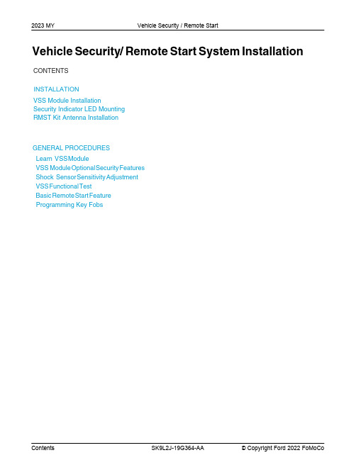
2023年模型年型福特VSS系统安装指南说明书
2023 MY Vehicle Security / Remote StartVehicle Security/Remote Start System Installation CONTENTS,167$//$7,21V SS Module InstallationSecurity Indicator LED MountingRMST Kit Antenna InstallationGENERAL PROCEDURESLearn V SS M oduleVSS M odule O ptional S ecurity F eaturesShock S ensor S ensitivity A djustmentVSS F unctional T estBasic R emote S tart F eatureProgramming Key FobsINSTALLATIONVehicle Security / Remote StartVSS System ComponentsSecurity Indicator LED (19D596) "Optional"Review VSS Kit ContentsNOTE:Kits are vehicle specific and are not interchangeable.1.Verify correct kit part number.2.Review the VSS kit contents.Vehicle Security System (VSS) KitQUANTITY DESCRIPTION1VSS Module1T-harness6Tie-strapsVehicle Security System (VSS) Kit(Continued)1Owner's Manual2Key Tags (not shown)Security Indicator LED Kit Contents "Optional"3.Verify correct kit part number.4.Review the Security Indicator LED kit contents.Security Indicator LED KitQUANTITY DESCRIPTION1Security Indicator LEDI.VSS System Installation - All VehiclesCAUTION:Carefully route and secure module and harnesses so that they do not interfere with moving parts or linkages.NOTE:If the VSS kit was installed previously and the vehicle is being upgraded, proceed to the "RMST" upgrade section(s).5.If the vehicle is equipped with factory remote start, test its operation by pressing the Lock buttonone time and the Remote Start button two times.•If the vehicle remote starts, stop the engine by pressing the Remote Start button one time.•If the vehicle does not remote start, diagnose the concern.6.Disconnect the vehicle battery negative terminal. For additional information, refer to WSM Section414-01.7.Disconnect the Gateway Module electrical connector, plug the VSS T-harness into the back of themodule and plug the other end of the VSS T-harness into the vehicle harness.NOTE:Explorer and Aviator, The gateway module (GWM) is located under driver side dash on the back side of the fuse box.NOTE:Edge and Nautilus, The enhanced central gateway (ECG) module is located behind the right rear quarter panel.NOTE:F-150, Expedition and SuperDuty, The enhanced central gateway (ECG) is located under the Front Display Interface Module, behind the sync module. For additional information refer to Workshop Manual (WSM) section 418-00.NOTE:Navigator, The enhanced central gateway (ECG) is located on the Driver Side C-Pillar. For additional information refer to Workshop Manual (WSM) section 418-00.NOTE:Transit, The SYNC 4 enhanced central gateway (ECG) is located behind the glove compartment on the top side, for SYNC 3 vehicles please refer to the "all other vehicles section". For additional information refer to Workshop Manual (WSM) section 418-00.NOTE:Bronco, The enhanced central gateway (ECG) module is located behind the glove compartment.NOTE:Escape and Corsair, The enhanced central gateway (ECG) is located under the center console. For additional information, please refer to Workshop Manual (WSM) Section 501-12.NOTE:For all other vehicles.8.Position the VSS harness inside the IP being careful to avoid sharp edges and moving parts.9.Install and secure the VSS module to the instrument panel frame or wiring harness on the driverside of the vehicle to the left of the steering column.•Ensure the VSS module is positioned so the shock sensor adjustment knob can be accessed for later use.•Ensure the tie-strap is routed through the VSS module loops at opposite corners.10.Connect the VSS harness to the VSS module.•Secure the VSS harness with tie-straps.11.Connect the vehicle battery negative terminal. For additional information, refer to WSM Section414-01.Optional Security Indicator LED MountingCAUTION:Carefully route and secure the LED and harness so that it doesn't interfere with moving parts or linkages.12.Keep the following points in mind when routing or positioning the LED for mounting:•Have at least 3/4" clearance behind trim panels for the wiring harness to be routed.•The LED should be clearly visible from the driver's side window when mounted.•Do not mount the LED on trim panels that cover air bags.13.Mount the LED at an appropriate location on the upper steering column shroud, using the guidelineslisted above.•Drill a 9/32" hole into the selected location, for the LED to mount in.14.Route the LED wire harness to the VSS module.15.Connect the LED wire harness to the VSS module 2-pin white connector.•Secure the LED wire harness with tie-straps.Learn VSS Module to VehicleNOTE:Make sure the brake pedal is not depressed during this sequence.16.Cycle ignition key ON then OFF.17.Upon ignition OFF, vehicle doors will lock then unlock.VSS Module - Optional Vehicle Security Features18.Start with ignition key OFF, doors unlocked and VSS system DISARMED.19.Place shifter in the PARK position (remaining in PARK).20.Open driver door (remaining open throughout).21.Depress and hold the brake pedal.22.NOTE:Brake pedal application is only required during the first ignition ON then OFF cycle.Cycle ignition key ON then OFF 5 times, then back to the ON position a 6th time. Keep ignition key in the ON position for the remainder of the program cycle.NOTE:The horn will sound 3 times.23.Close the driver door.24.Open the driver door.25.Close the driver door. The vehicle's horn will sound 1 time to indicate the security enable/disableoption has been accessed.26.Applying and releasing the brake pedal will toggle the security feature on/off.•The horn will sound once to indicate the security feature is ON.•The horn will sound twice to indicate the security feature is OFF.27.Cycle ignition key to the OFF position to exit security enable mode.Shock Sensor Sensitivity AdjustmentNOTE:The VSS module is equipped with an internal dual zone Shock Sensor. The VSS system will sound the horn and flash the lights once anytime a light to moderate impact is detected, and a "panic" horn sound/ light flash for a 30 second sequence when a heavy impact is detected while the VSS system is armed. Adjustment of both zones is accomplished through a single adjustment knob on the VSS module. Rotating the knob clockwise will increase sensitivity and rotating the knob counter-clockwise will decrease sensitivity. Sensitivity adjustment must be completed with the module securely mounted and the adjustment knob accessible.28.Starting with the adjustment knob in approximately the halfway position, lower the driver's windowand exit the vehicle.29.Press the LOCK button on the vehicle's RKE fob to arm the VSS system. If equipped, the LED willlight solid for 20 seconds and then begin to flash a steady on/off sequence to indicate the system is armed.ing a closed fist, impact the steering wheel with moderate force to simulate a light impact on thevehicle. If the impact is detected, the horn will sound and the lights will flash 1 time to indicate the warning impact was detected.ing a closed fist, impact the steering wheel with heavy force to simulate a hard impact (i.e. glassbreakage) on the vehicle. If the impact is detected, the horn will sound and the lights will flash a steady on off sequence to indicate the heavy or full shock trigger was detected.32.Increase (rotate clockwise) or decrease (rotate counter-clockwise) the adjustment knob as necessaryto achieve desired sensitivity, repeat the previous steps to test, and verify adjustment.VSS Functional TestNOTE:INSTALLATION (Continued)If installed, observe the LED while performing these tests.33.Lower the driver's door window, then close all doors, hood, and trunk/hatch and press lock on thekeyfob. The LED should stay lit for 20 seconds while the VSS system pre-arms, after which it will flash every 3-4 seconds in fully armed mode.34.Reach inside the window hit the door unlock trim switch. The LED should continue to flash,indicating that the vehicle is still armed. Use the inside driver's door handle to open the door. The alarm should sound, indicating perimeter breach. Turn the alarm off by turning the ignition to "On".•If equipped with OE perimeter security, there will be a 12 second interior chime prior to alarm sounding. For vehicles not equipped with OE perimeter security, there will be a 12 second delay with no interior chime prior to alarm sounding.•For push button start vehicles, the Intelligent Access (IA) key must be away from the vehicle, otherwise the security system may disarm immediately upon trigger.35.Exit the vehicle and arm it again, this time leaving the driver's door open. The vehicle should armitself, ignoring the open door but monitoring the rest. Once the vehicle is armed, shut the driver's door and reopen it after a few seconds. The alarm should sound. Turn the alarm off by hittingunlock on the keyfob.•For push button start vehicles, the Intelligent Access (IA) key must be away from the vehicle, otherwise the security system may disarm immediately upon trigger.36.Test all other vehicle doors, the hood and the trunk in the same manner, by setting off the alarm anddisarming with the keyfob.37.Please contact 1-800-FORD-KEY with any issues regarding hardware or kit contents. Standard Key Fob (15K601) "Sold Separately"Basic Remote Start Feature38.Enable/Disable Basic Remote Start Features:Locate the jumper supplied in the kit.•Install the jumper to the VSS module if the Basic Remote Start feature is to be enabled .•Not installing and/or removing the jumper from the VSS module will keep the Basic Remote Start feature disabled.Bi-directional Key Fob (15K601) "Sold Separately"Programming Key Fobs39.Key Start Vehicles:1Start with ignition key OFF, doors unlocked and VSS system DISARMED.2Open driver door (remaining open throughout).3Place shifter in the PARK position (remaining in PARK).4Depress and hold the brake pedal.5Cycle ignition key ON then OFF 5 times, then back to the ON position a 6th time.▪The horn will sound 3 times to indicate transmitter learn mode access.6Press and hold the remote start button for 3 seconds on each fob you wish to program (horn will sound indicating successful programming).7Cycle ignition key to the OFF position to exit transmitter learn mode.40.Push Button Start Vehicles:NOTE:The following steps must be performed with the driver door open.1Enter the vehicle with the vehicle key(s) and key fobs you wish to program. Doors should be unlocked and vehicle security disarmed.2Depress and hold brake pedal.3Press the start/stop button.4After the vehicle starts, press the start/stop button to shut down.5Repeat steps 3 and 4 an additional 5 times, ending in ignition ON, engine ON.NOTE:The horn will sound 3 times to indicate transmitter learn mode access (some vehicles may notsound the horn 3 times).6Press and hold the remote start button for 3 seconds on each fob you wish to program (horn will sound indicating successful programming).7Cycle ignition to the OFF position to exit transmitter learn mode.RMST Functional Test41.Make sure the shift lever is in PARK and the ignition is in the OFF position. Remove all keys fromthe vehicle.42.Close the hood.43.Roll window down.44.Close all of the vehicle doors.45.Start the vehicle by pressing the remote start button twice within 3 seconds on the remote start keyfob.46.Confirm the remote start works with the vehicle in park and with the hood and doors closed.47.Confirm full A/C and heat operation of the climate controls. If climate controls are inoperative,follow normal diagnostic procedures using the WSM.48.Open the hood.49.NOTE:Vehicle doors should be closed while performing this step.Confirm that the vehicle will not remote start with the hood open.Please contact 1-800-FORD-KEY with any issues regarding hardware or kit contents.50.See the Scalable Remote Start System Diagnosis Guide to resolve issues identified by the functionaltest.Optional RMST Upgrade Components "Sold Separately"51.Review the RMST Upgrade components.Remote Start (RMST) Upgrade - Antenna Kit "Sold Separately"QUANTITYDESCRIPTION 1Extended Range Antenna (15603)Extended Range Antenna Installation (Optional)52.Clean the antenna mounting surface using an alcohol base solution and a clean cloth.II.Remote Start (RMST) Upgrade - Antenna Kit "Sold Separately"CAUTION:Carefully route and secure the antenna and harness so that they do not interfere with moving parts or linkages.54.Position the LH A-pillar trim slightly outward to provide access to route the antenna wire.NOTE:Do not route the antenna wire over the top of air bags.55.Route the antenna cable along the headliner and down the LH A-pillar towards the floor. Continuerouting the wire Into the IP towards the VSS module.•Secure with tie-straps.56.Connect the antenna connector to the VSS module.57.Reposition the A-pillar trim panel back.53.NOTE:Do not touch the adhesive, reduced adhesion may result.NOTE:Make sure that the long wire on the antenna is pointing towards the top of the windshield since this wire will be routed along the headliner.NOTE:The wire will be attached to the control module later in this procedure.Remove the protective backing from the adhesive on the antenna and firmly press the body of the antenna onto the mounting surface.。
福特性能竞技部件安装指南说明书
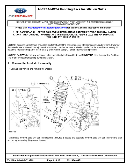
NO PART OF THIS DOCUMENT MAY BE REPRODUCED WITHOUT PRIOR AGREEMENT AND WRITTEN PERMISSION OFFORD PERFORMANCE RACING PARTS.Please visit for the most current instruction information! ! ! PLEASE READ ALL OF THE FOLLOWING INSTRUCTIONS CAREFULLY PRIOR TO INSTALLATION.AT ANY TIME YOU DO NOT UNDERSTAND THE INSTRUCTIONS, PLEASE CALL THE FORD RACINGTECHLINE AT 1-800-367-3788 ! ! !NOTICE: Suspension fasteners are critical parts that affect the performance of vital components and systems. Failure of these fasteners may result in major service expense. Use the same or equivalent parts if replacement is necessary. Do not use a replacement part of lesser quality or substitute design. Tighten fasteners as specified.NOTICE: Do NOT discard any fasteners unless specifically instructed to do so IN WRITING. Use the supplied Red Loc-Tite to ensure fastener locking during installation.1.Remove the front strut assembly1.1 Jack up the vehicle and remove the wheels.1.2 Remove the front stabilizer bar link upper nut (pictured 3 above) and separate the front stabilizer bar link from the strut and spring assembly. Dispose of the nuts.NO PART OF THIS DOCUMENT MAY BE REPRODUCED WITHOUT PRIOR AGREEMENT AND WRITTEN PERMISSION OFFORD PERFORMANCE RACING PARTS.1.3 Remove the brake hose bracket bolt and disconnect the wheel speed sensor wire from the bracket. Set the bolt aside.1.4 If equipped, disconnect the front strut electrical connector.1.5 Using a suitable jackstand, support the lower control arm.NO PART OF THIS DOCUMENT MAY BE REPRODUCED WITHOUT PRIOR AGREEMENT AND WRITTEN PERMISSION OFFORD PERFORMANCE RACING PARTS.1.6 Remove the strut-to-spindle bolts and flagnuts, and discard the nuts.NOTE: Original strut-to-wheel spindle bolts are splined and may need to be driven out.1.7 NOTICE: Damage to the lower control arm bushings may occur if the lower control arm is not supported. Carefully lower the lower control arm and remove the strut and spring assembly.2.Remove the front stabilizer bar assembly2.1 If equipped, remove the 9 screws and the lower air deflector. Set the screws aside.2.2 Loosen the 2 crossmember brace nuts. Set the nuts aside.NO PART OF THIS DOCUMENT MAY BE REPRODUCED WITHOUT PRIOR AGREEMENT AND WRITTEN PERMISSION OFFORD PERFORMANCE RACING PARTS.2.3 Remove the 6 crossmember brace bolts and remove the crossmember brace. Set the bolts aside.2.4 Remove and discard both stabilizer bar link lower nuts.2.5 Disconnect both links from the stabilizer bar.2.6 Remove the 4 stabilizer bar bracket nuts and carefully remove the stabilizer bar.3.Install the new Ford Performance front sway bar3.1 Assemble the new bushings on the Ford Performance front swaybar, utilizing the provided lubrication grease between the bushing and the bar.3.2 Install the new front swaybar brackets over the bushings, and position the new Ford Performance front sway bar over the factory studs.NOTICE: When installing the stabilizer bar, make sure the stabilizer bar is centered symmetrically between the 2 stabilizer bar brackets. The distance between the stabilizer bar brackets and links should be the same on both sides, as shown in the illustration.NO PART OF THIS DOCUMENT MAY BE REPRODUCED WITHOUT PRIOR AGREEMENT AND WRITTEN PERMISSION OFFORD PERFORMANCE RACING PARTS.3.3 Install the 4 stabilizer bar bracket nuts, and tighten to 70 Nm (52 lb-ft).3.4 Reinstall the chassis crossmember brace with the 6 bolts and tighten to 48 Nm (35 lb-ft).3.5 Reinstall the chassis crossmember brace nuts and tighten to 48 Nm (35 lb-ft).3.5 Reinstall the 9 screws for the lower air deflector.NO PART OF THIS DOCUMENT MAY BE REPRODUCED WITHOUT PRIOR AGREEMENT AND WRITTEN PERMISSION OFFORD PERFORMANCE RACING PARTS.4.Install the new Ford Performance front strut assemblies4.1 Position the new Ford Performance strut assembly into the strut tower, and use the new strut top nuts and tighten to 26 lb ft (35 Nm).4.2 Install the strut assembly to the knuckle, using a provided eccentric bolt for the lower and a factory bolt for the upper. Use the new supplied nuts and tighten to 166 lb-ft (225 Nm).4.3 If equipped, reconnect the front strut electrical connector.NO PART OF THIS DOCUMENT MAY BE REPRODUCED WITHOUT PRIOR AGREEMENT AND WRITTEN PERMISSION OFFORD PERFORMANCE RACING PARTS.4.4 Reconnect the wheel speed sensor wire from the bracket. Reinstall the brake hose bracket bolt and tighten to 20 Nm (177 lb-in).4.5 Reinstall the stabilizer bar links with the provided new nuts on both the strut and the stabilizer bar. Tighten to 115 Nm (85 lb-ft).5. Remove the rear stabilizer bar5.1 Remove and discard the stabilizer bar link bolts and clip nuts (labeled 1 and 2 above).5.2 Remove the stabilizer bracket nuts (labeled 3 above)NO PART OF THIS DOCUMENT MAY BE REPRODUCED WITHOUT PRIOR AGREEMENT AND WRITTEN PERMISSION OFFORD PERFORMANCE RACING PARTS.6. Remove the rear shocks, springs, and jounce bumpers6.1 Open the luggage compartment and position the carpet aside.6.2 NOTICE: Do not support the rear axle at the differential housing or damage to the housing may occur. NOTICE: Do not allow the axle assembly to hang supported only by the upper control arm or lower control arms. This could damage the control arm bushings.Using 2 suitable jackstands, support the rear axle.6.3 Remove and discard the shock absorber upper nut, washer and insulator assembly (1 below).6.4 Remove and discard the shock absorber lower bolt and nut (2 and 3 above) and remove the shock absorber.NO PART OF THIS DOCUMENT MAY BE REPRODUCED WITHOUT PRIOR AGREEMENT AND WRITTEN PERMISSION OFFORD PERFORMANCE RACING PARTS.6.5 Remove the brake hose bracket bolt (8 below) and set aside.6.6 Lower the rear axle and remove the spring.6.7 Remove and discard the 2 bolts attaching the bump stops, and remove the bump stops.7. Remove the panhard rod.7.1 Using 2 screwdrivers inserted through the access hole, depress the tabs of the panhard rod bolt cover retaining clip and remove the cover.NO PART OF THIS DOCUMENT MAY BE REPRODUCED WITHOUT PRIOR AGREEMENT AND WRITTEN PERMISSION OFFORD PERFORMANCE RACING PARTS.7.2 Remove the panhard rod bolts and flagnuts (1, 2, and 3 below) and set them aside.8. Install the new Ford Performance panhard rod.8.1 Set the new Ford Performance panhard rod and the factory rod side by side. Use the bolts to line the eyes of the panhard rods up and set the length of the new rod to match the factory rod. Tighten the jam nuts on the Ford Performance panhard rod.8.2 Install the new Ford Performance panhard rod, and tighten the bolts to 175Nm (129 lb-ft).8.3 Reinstall the panhard rod access cover.9. Install the new Ford Performance springs and jounce bumpers9.1 Install the new Ford Performance bump stops using the provided bolts.9.2 Install the new Ford Performance rear springs and ensure that the springs are seated properly in the spring seat.10. Install the new Ford Performance stabilizer bar and rear shocks10.1 Prepare the stabilizer bar for installation by greasing the new bushings and installing the inner and outer bushings to the bar.10.2 Assemble the endlinks to the inner bushings using the included hardware.NO PART OF THIS DOCUMENT MAY BE REPRODUCED WITHOUT PRIOR AGREEMENT AND WRITTEN PERMISSION OFFORD PERFORMANCE RACING PARTS.10.3 Install the Ford Performance stabilizer bar to the axle housing using the provided backing plates and swaybar brackets. Tighten the included hardware to 70 Nm (52 lb-ft).10.4 Using the provided new nuts and bolts (2 and 3 below), install the Ford Performance rear shocks. Tighten to 115 Nm (85 lb-ft)NO PART OF THIS DOCUMENT MAY BE REPRODUCED WITHOUT PRIOR AGREEMENT AND WRITTEN PERMISSION OFFORD PERFORMANCE RACING PARTS.10.5 Raise the rear axle. Reinstall the brake brackets (8 below) and tighten to 20 Nm (177 lb-in).10.6 Install the stabilizer bar endplates to the body (5 and 7 above) and tighten to 115 Nm (85 lb-ft).10.7 Install the shocks to the body using the new included upper nut, washer and insulator assembly (1 below).NO PART OF THIS DOCUMENT MAY BE REPRODUCED WITHOUT PRIOR AGREEMENT AND WRITTEN PERMISSION OFFORD PERFORMANCE RACING PARTS.11. Install the wheels and tires11.1 Tighten the wheel nuts in a star pattern. Torque: 148 lb.ft (200 Nm)12. Set desired alignment12.1 Choose either Ford factory Performance Pack alignment specification, or Ford Performance Suggested alignment.Factory Spec Camber Caster Total ToeFront -0.75 7.1 0.22Rear N/A N/A .05Ford Performance Spec Camber Caster Total ToeFront -1.2 7.1 0.22Rear N/A N/A .05NOTE: Ford Performance alignment specification may result in accelerated tire wear, with the benefit of improved vehicle response and handling.。
正品先锋福克斯专车专用DVD导航一体机导购及安装指南
◆ 3D都市实景和3D建筑的导航地图 ◆ 智能联想输入
◆ 支持模糊检索
◆ 支持在地图界面中操控多媒体播放
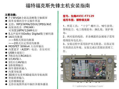
型号:先锋AVIC-F7129 适用车型:福特福克斯 1、所需工具:“十字”螺丝刀、10号套筒、 塑料胶刀、电工绝缘胶布、捆扎线、保护垫 布; 2、两对接的线组、多余裸露的金属端子需用 绝缘胶布包扎好; 3、安装过程中需用防护布及鞋套,以保证原 车的清洁及外观,安装完成后需做好清理工 作。
淘宝adminztw点taobao点com/
原车音响中控台
用胶刀撬松装饰框
取下装饰框
取下四颗螺丝后,取下音响(注意扣位)
原车音响接线图
连接专用线束插头
原车音响正面效果图
原车USB\AUX接口
斯文文
GPS天线安装参考位置
取下机芯两颗螺丝
音响专用线束插头功能说明
收音天线插头
GPS插头
CAN插头数字电视插头
电源插头
音频输入输出插头
喇叭线插头
多功能3个并排插头
用胶布包扎专用线束
改装后音响中控效果图
安装还原后测试功能 本资料由聆听世界汽车影音之家淘宝店提供 淘宝店地址:adminztw点taobao点com/
Байду номын сангаас
福特福克斯先锋主机安装指南
主要功能:
◆ 7寸WVGA全新高清晰数字触摸屏 ◆ 简单易懂的全中文操作界面
◆ 支持:MP3/WMA/DIVX/JPEG/AVI ◆ 高保真收音(FM/AM)
可预置18FM/12AM电台 ◆ 5.1声道环绕Dolby Digital数字解码器 ◆ 16段均衡器
——5模式预设均衡器 ——2模式自定预设均衡器 ◆ MOSFET 50Wx4 大功率输出 ◆ 内置蓝牙(A2DP)电话,音乐对应 ◆ USB全速接口 ◆ 7路高电压RCA输出 ◆ 1组AV输入 ◆ 1组后台AV输出 ◆ 1路视频输出 ◆ 倒车摄影机输入
福特(Ford)电动汽车充电网络访问设置指南说明书
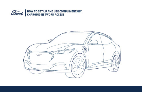
HOW TO SET UP AND USE COMPLIMENTARY CHARGING NETWORK ACCESS2. 2.2.4.Connect your vehicle modem to your Ford account:A. Either during the purchase process: Login to the eCommerce website to complete your purchase and e-sign all required documents.Enter your e-signature in the field provided on the FordPass Connect modem activation page and click“Submit”.B. Or in the FordPass App at delivery: Login to the FordPass App.Enter or scan your vehicle identification number (VIN).Click Activate your FordPass Connect vehicle modem.At delivery, click “Yes” on the Enable FordPass Connected Services in-vehicle screen.Next, go to /ConnectedServices to activate your FordPass Charging Network and complimentary 250kWh of fast charging. Note: You’ll be asked to verify/add a default pay-ment method into your Ford Wallet. This is in case you do any charging that is not free or included in the complimentary fast charging.Lastly, go to the FordPass App and toggle on “Plug & Charge” (Vehicle —> Manage EV —> FordPass Charging Network —> Plug and Charge) to automatically charge your default payment method when you plug into participating charging stations.In the FordPass AppA. Click on the “View Nearby Chargers” button on the FordPass App home screenB. Modify filters for the type of charger you want (default filters are DC Fast Charger, In-Network)In the Mustang Mach-E in-vehicle screen1. Click on “Navigation” (click upper center button > Nav button will appear in app list below)2. Click the search icon (labeled “Where To?”)3. Click “Charging Stations” button4. Click the “Filters” button at top right to turn on filters such as Fast Charge, Available and Open, In-Ford networkIf at an Electrify America station, simply plug in and your charging starts automatically via the Plug & Charge feature using your complimentary 250kWh of fast charging; after your complimentary kWh are used, your charging will still start au-tomatically and will bill you at the per kWh or per minute rate mentioned on the charging stationIf not at an Electrify America station, plug into the Mustang Mach-E charge port and search for the charger in the FordPass App using the steps in “Locate”.A. Click the “Preview Information” panel for the charger you are trying to use. If it is not a FordPass Charging Network station (Not “In-Network” in the FordPass App), follow instructions at the site.B. If there are multiple types of chargers at that site, click the port type the vehicle is plugged into (fast charger “DC CCS” or slower charger “J-1772”)C. Click “Select” near the charge plug icon you are plugged intoD. Click on the charge station with the same identifier asthe one at which you are plugged in E. Click “Activate”1. 1.1.2.2.3.1.1.3.SET UPLOCATECHARGETroubleshooting Tip: Turn off “pop up blocker“ and clear cookies on your internet browser. Make sure you have a credit card added to your “Wallet” in FordPassActivate your FordPass Charging Network access and complimentary 250kWh of fast charging at /ConnectedServices.Note: You’ll be asked to verify/add a default payment method into your Ford Wallet. This is in case you doany charging that is not free or included in the complimentary fast charging.Toggle on “Plug & Charge” in the FordPass App to automatically charge your default payment method when you plug into participating charging stations1.Troubleshooting Tip: Turn off “pop up blocker“ and clear cookies on your internet browser. Make sure you have a credit card added to your “Wallet” in FordPassClick on the “View Nearby Chargers” button on the FordPass App home screenModify filters for the type of charger you want(default filters are DC Fast Charger, In-Network)Click “Charging Stations” buttonClick the search icon (labeled “Where To?”) 2.3. MUSTANG MACH-EHOW TO CHARGE AND USECOMPLIMENTARY CHARGING NETWORK ACCESS2. 3.0.0 MI0.0 MIHOW TO USEPOWER MY TRIP(EV TRIP PLANNING)3. 4.5. 6.7.ADDITIONAL CHARGE STATION ACTIVATION INFORMATIONIf at an Electrify America station, simply plug in and your charging starts automatically via the Plug & Charge feature (if you have toggled on this feature in your FordPass App) using your complimentary 250kWh of fast charging; after your complimentary kWh are used, your charging will still start automatically and will bill you at the per kWh or per minute rate mentioned on the charging stationElectrify America is the only company to offer Plug & Charge at this point in time. It should be noted that you can also pay for charging at Electrify America using the FordPass App (as described below); your complimentary 250kWh will be used first, and then you’ll be billed at the per kWh rate mentioned on the charging station. If Plug & Charge is enabled but is not working at that Electrify America station, unplug and plug in again and when paymentscreen appears on station then follow steps below for activation by App.If not at an Electrify America station, plug into the Mustang Mach-E charge port and search for the charger in the FordPass App using the steps above (if subscribed). Click the “Preview Information” panel for the charger you are trying to use. If it is not a Ford-Pass Charging Network station (Not “In-Network” in the FordPass App), then follow instructions at the site.If there are multiple types of chargers (fast charger “DC CCS” or slower charger “J-1772”) at that site, click the port type the vehicle is plugged into.Click “SELECT” near the charge plug icon you are plugged into.Look for the identifier either on the charge station or on the charger screen. In FordPass, click on the charge station with the matching identifier as the one at which you are located.Click “ACTIVATE”1.A.B.2.3.4.5.6.。
罗克福德福特 vague接口模块 для选定的马斯verify车辆载入akespeare说明书

Serial Number:Date of Purchase:Installation & Operation®Interface Modulefor selected Mazda vehicles2ContentsIntroduction and Precautions ...................................2Supported iPod Models .............................................3Pre-System Setup ...................................................3-4Installation ..................................................................5Operation ................................................................6-8Auxiliary Audio Source .............................................9T roubleshooting .......................................................10Warranty (11)Introduction and PrecautionsThank you for purchasing the Rockford Fosgate Interface Module for iPod. The Interface Module was designed and manufactured to seamlessly integrate with your vehicle’s factory system. T o get the best performance from this device, read this manual before doing any type of installation.This symbol with “CAUTION ” is intended to alert the user to the presence of important instructions. Failure to heed the instructions can result in injury, damage to the vehicle or unit damage.CAUTION: T o prevent injury and damage to the unit, please read andfollow the instructions in this manual. We want you to enjoy this system, not get a headache.CAUTION: I f you feel unsure about installing this system yourself, have itinstalled by a qualifi ed Rockford Fosgate technician.CAUTION: B efore installation, disconnect the vehicle battery, bothpositive (+) and negative (-) terminals, to prevent damage to the unit, fi re and/or possible injury.CAUTION: F or your safety, ensure the iPod interface module is mountedin a location that will not interfere with the proper and safe operation of the vehicle.©2009 Rockford Corporation. All rights reserved.Rockford Fosgate and the Rockford Fosgate logo, are either registered trademarksor trademarks of Rockford Corporation.iPod is a trademark of Apple, Inc.Supported iPod ModelsiPod FirmwareFor proper operation of the interface module,ensure your iPod is updated with the latest fi rmware.Free updates can be downloaded from http://ipod/ download/.The directions on the site will guide you through the update process.Pre-System SetupInterface Module DIP Switch SettingsProper identifi cation of your system and correct setting of the DIP switches will ensure the interface module operates properly when installed.DIP Switch Positions Switch SwitchNOTE: If you change the positions of the DIP switches after the module is installed,turn off the vehicle ignition,disconnect the ‘Vehicle Harness’from the interface module,then wait one (1) minute before reconnecting the harness and turning the vehicle ignition on.34Pre-System SetupDIP Switch Setting for Car Switch on the Interface ModuleDIP Switch Setting for iPod Switch on the Interface ModuleInterface ModuleMazda CDC Integration 12ON12Car SwitchSet Car Switches to;CD Changer (CDC)iPod SwitchBothSwitches OFF (Default)BothSwitchesOFF(Default)Both Switches OFF (Default)Mazda SAT Integration Set Car Switches to;Single Text FieldsRecommended for Nav radios,or Non-Nav radios when 29 character manual-scrolling is preferred.Recommended for CDC Integration, or when Text Display is NOT supported by the radio.Recommended for SAT Integration,or when controlling fromthe radio is preferred.Recommended for Non-Nav radios.Only 8 character auto-scrolling can beselected in Text Scroll Settings (see Operation)Either 8 character auto-scrolling or 29 charactermanual-scrolling can be selected in Text Scroll Settings (see Operation)In this setting the Name and Title text fields display identical song information. (Song Name * Album * Artist)Set Car Switches to;Dual Text FieldsSet Switch 1to ON Set Switch 2to OFFIn this setting the Title text field displays Album and Artist.Name text field displays Song Name.˝Radio˝Both Switches ON˝iPod˝Use this mode to browse within the contents of the iPod by category as shown in the ‘Operation’ section.Set iPod Switches to;Content is selected on the iPod.Content is only selected fromthe radio and the iPod is locked.Track numbers and times are not synchronized between the iPod and radio.This mode has the fastest response time.12Interface Module12ON12Car SwitchiPod Switch12Interface Module12ON12Car SwitchiPod Switch12Interface Module12ON12Car SwitchiPod Switch12Set iPod Switches to;Interface Module12ON12Car SwitchiPod Switch12InstallationIt is recommended that installation only be performed by a qualifi ed professional.Beware of sharp edges to avoid injury and exercise caution when removing trims as they may break.The module should be placed at an accessible location to allow an AUX cable tobe connected,such as in the glove box,the center console or under the front seat.Ensure the mounting location does not interfere with the safe operation of the vehicle (i.e..near steering,foot pedal controls,parking brake or shifter).1.Be sure to carefully read and understand the instructions before attempting to installthe unit.2.Disconnect both battery terminals.These cables must be disconnected duringinstallation to ensure proper initialization of the interface module when it is connected.3.Carefully remove surrounding trim to access the radio mounting screws.Most trims canbe removed by carefully pulling on the piece or using trim removal tools.Trim is usually held in place by snap-in clips.4.Remove the 10mm bolts that hold the radio in place.Carefully pull the radio away fromthe console.T ake care not to damage the wire connections at the back of the radio.Consult your dealership if additional information is needed on removing the radio. NOTE: When routing harnesses or cables,ensure they are secured away from sharp edges and moving parts by the use of cable ties.5.The CD changer/SAT port is located on the back of the radio.Unplug the factoryconnection if present and plug the supplied interface harness into the receptacle on the radio.Plug the factory connection back into the harness receptacle,if it was removed.Ensure all connections are securely locked in place.6.Prior to making any connections to the interface module,ensure DIP switches are setcorrectly (see Vehicle Identifi cation and Pre-System Setup).7.Vehicle connector onthe interface module.8.Connect the iPod cable tothe interface module andcarefully route it to thelocation where the iPodwill be mounted(such as the glove boxor center console).9.Verify that all connectionshave been properly made.10. Reinstall the radio andreconnect the vehiclebattery.Turn the ignitionreinstalling the panels/trim.56Connecting Y our iPodSimply connect your iPod to the interface cable coming from the interface module. The interface automatically charges the battery of the iPod when connected and the key is in the ACC/ON position. The charging icon will appear on the upper right corner of the iPod screen to indicate charging.NOTE:turned off.iPod HierarchyBy default, the interface creates a Playlist having a name that is the same as the name of the iPod. This Playlist is the very fi rst on the list ofPlaylists shown while browsing in Playlist mode. This Playlist contains all the songs on the iPod. Once a Playlist is active an Artist may be selected within that Playlist using the Artist Mode. Albums by the selected Artist and within the selected Playlist may be selected in Album Mode. “ALL ARTIST” and “ALL ALBUM” designate all available content in those categories.CDC Integration Controls (interface module iPod switch set to ˝iPod˝)Press the CD button to access the interface and its features. Pressing the CD buttonrepeatedly will cycle through sources present (internal CD if present, followed by external) in your vehicle. When the iPod audio source is active (displayed as DISC 5, Track 1), use the SEEK button to select next/previous song.Mode Selection – Browsing (CDC Integration)Once the iPod is connected and selected as the audio source, you can browse through the modes by selecting one of the DISC buttons (1-5). Browse through the modes as follows;TRACK » PLAYLIST » ARTIST (within the selected Playlist) » ALBUM (within the selected Artist in the selected Playlist) » AUDIO SOURCEChange Tracks within that mode by pressing the SEEK button. T ext display is not supported, however recent iPod fi rmware upgrades show the Title/Artist information of the currently played song. Playlist Artist AlbumSongM o r e b r o w s a b le c o n te n tL e s s b ro w s a b l e c o n t e n tSAT Integration Controls (interface module iPod switch set to ˝Radio˝)Press the SAT button to access the interface and its features.When the iPod integration is accessed for the fi rst time,the radio will display “UPDATING” for about one minute.The audio source should be set to iPod.NOTE: If the radio continues to display “UPDATING” for more than one minute,turn off the radio and then back on.By Double-Clicking the SEEK button you can browse through the Modes as follows; TRACK » PLAYLIST » ARTIST » ALBUM » AUDIO SOURCE » VER.(version)/TEXTSETTINGSBrowse within that mode by pressing the SEEK (next track / previous track) button once. NOTE: T o avoid mode switching,wait until the specifi c mode is displayed before pressing the SEEK (next track / previous track) button.If nothing is pressed for 30 seconds,the browsing returns to Track mode.EXAMPLE78T oggling between text fi elds (SAT Integration)By pressing the TUNE KNOB you can toggle through the text fi elds as follows;Channel Number » Channel Name (fixed) » Category Name (fixed) » Title (displays Album * Artist) » Name (displays song name)NOTE: On Non-Nav radios the last two (Title and Name) are shown on one lineas Song * Album * Artist.T ext Scrolling Settings (SAT Integration)T ext scrolling will work in two different ways, depending on the car DIP switch settings. If the car switch on the interface module was set to ˝Single T ext Mode˝, the radio will always auto-scroll 8 characters. Turning the TUNE KNOB has no effect.If the car switch on the interface module was set to ˝Dual T ext Mode˝, there is an option to select between 8 character auto-scroll and 29 character manual-scroll text display settings.Change the settings as follows;EXAMPLEWhen 29 character manual-scroll text is selected, turning the TUNE KNOB scrolls the text displayed.T ext only scrolls when TUNE KNOB is turnedT ext automatically scrolls Double-Click SEEK button until Press TUNE KNOB to select betweenVER. and TEXT SETTINGSAuxiliary Audio SourceConnectingThe interface is equipped with a 1/8”AUX jack input to connect an auxiliary device,such asan MP3 player,DVD player or other audio source.NOTE: We recommend to only connect to the interface module when the vehicle ignitionis turned off.your auxiliary device with a cable thathas a 1/8” mini stereo jack (not included).Selecting AUX InputT o access the AUX audio source,use the Source Selector (CD button in CDC integrationand SAT button in SAT integration) to access the interface module and then press theSEEK (next track) button to toggle between SEL:AUX and SEL:IPODAUX audio source settingsThe auxiliary input has settings for Gain (volume),Bass,Mid and Treble in order to optimizesound.Gain (Volume) should be adjusted if the audio level from the auxiliary device is too lowor too high.If you hear distorted audio while playing the auxiliary device,you need toreduce (-) the gain.If you notice that the audio is too quiet then the gain setting shouldbe increased (+).The default setting for gain is “68” and may be adjusted in incrementsbetween 01-99.Bass,Mid and Treble default settings are “50” and can be adjusted between 01-99 tocompensate for the acoustic presets of the radio.Making the adjustmentsWhile listening to the auxiliary device,use the DISC (Preset) buttons to move between thesettings as follows;DISC (Preset)-1 for Gain (Volume) DISC (Preset)-2 for Bass EQDISC (Preset)-3 for Mid EQ DISC (Preset)-4 for Treble EQThen use the TUNE KNOB or press the SEEK button up or down to adjust the setting.NOTE: If you are using an auxiliary device that is using the vehicle’s power source and not its own battery,you may have to use a GROUND-LOOP isolator to avoid engineand grounding noise.9TroubleshootingProblemCannot select the interface.No audio from iPod source.Radio/steering wheel controls do not operate iPod.Music is distorted or sound level is too low.No text display.iPod does not charge.SolutionCheck DIP switch settings (refer to Pre-System Setup). With the ignition OFF disconnect vehicle harness from module for one (1) minute and reconnect. Verify that the correct button is used to access the interface. 2004 Mazda-6 may require radio modifi cation to accept external CD changer connection.Reset the iPod. Verify proper connection to iPod/interface.Reset iPod and make sure most recent iPod fi rmware is installed. Check vehicle user manual on how steering wheel controls work.Check and make sure all EQ and BASS boost options are turned off on your iPod (refer to Auxiliary Audio Source).Make sure DIP switch settings are correctly set for text display (refer to Pre-System Setup).Check all connections. Reset iPod and make sure iPod charges while connected to computer or wall charger.10WarrantyThe Rockford Fosgate iPod Interface Module has a warranty of 1 Y ear.This warranty covers only the original purchaser of Rockford product purchased from an Authorized Rockford Fosgate Dealer in the United States.In order to receive service,the purchaser must provide Rockford with a copy of the receipt stating the customer name,dealer name, product purchased and date of purchase.Products found to be defective during the warranty period will be repaired or replaced (with a product deemed to be equivalent) at Rockford’s discretion.What is Not Covered1.Damage caused by accident,abuse,tampering,improper operations,water,direct sunlight,excessive heat,theft,shipping.2.Any cost or expense related to the removal or reinstallation of product.3.Service performed by anyone other than Rockford or an Authorized Rockford FosgateService Center.4.Any product which has had the serial number defaced,altered,or removed.5.Subsequent damage to other components.Limit on Implied WarrantiesAny implied warranties including warranties of fi tness for use and merchantability are limited in duration to the period of the express warranty set forth above.Some states do not allow limitations on the length of an implied warranty,so this limitation may not apply.No person is authorized to assume for Rockford Fosgate any other liability in connection with the sale of the product.How to Obtain ServiceContact the Authorized Rockford Fosgate Dealer you purchased this product from.If you need further assistance,call 1-800-669-9899 for Rockford Customer Service.11Rockford FosgateRockford Corporation600 South Rockford DriveT empe,Arizona 85281 U.S.A.In U.S.A.,480-967-3565Customer Service 1-800-669-989912/08 B.M.1230-55533-01Printed in U.S.A。
福特汽车VCM II无线设备说明书

perform the update.
8. Click on the "Device Selection" tab
located at the top right corner of the IDS screen (see
Figure 1: Device Selection Screen).
If the “Device Selection” tab is not visible, connect the VCM II to the computer using the USB cable.
V1.0
Page 4 of 16
April 25, 2012
VCM II Wireless User Manual
FIGURE 1: DEVICE SELECTION SCREEN
9. Select the VCM II that you would like to connect to.
DOWNLOAD AND INSTALL IDS SOFTWARE
If you have not already installed your IDS software onto your computer, please do so. Download the latest IDS software from one of the following web addresses.
1. Using the supplied D-Link Wireless Adapter. 2. Using a wireless access point or router.
These instructions explain how to set up a wireless VCM II for both.
福特远程启动系统安装指南.pdf_1718748198.5087342说明书

Proper Wire Splicing Techniques RKE/VSS/Remote Start System
2
GENERAL PROCEDURES (Continued)
6. Wrap the connection with electrical tape so the tape covers the wires approximately two inches on either side of the connection.
This installation instruction covers the installation of all Remote Start Kits.
Vehicle wiring is subject to change. All possible efforts have been taken to ensure that the information contained herein is accurate as of the revision dates indicated. As such, it is critical that vehicle circuits are tested prior to making any connections, to ensure that the proper vehicle circuit has been located.
Parts Warranty Processing:
Lifetime limited coverage to original purchaser on all components against defects and workmanship. (For complete Warranty details, please refer to the warranty section found at the rear of each Security or Remote Start systems Owners Manual) Contact the warrantor, Code Systems for return authorization/replacement approval for failed components at no charge by the manufacturer. Return of Components to Code Systems requires the following:
Ford F-150 豪华版 专业拖车后退辅助系统安装说明书
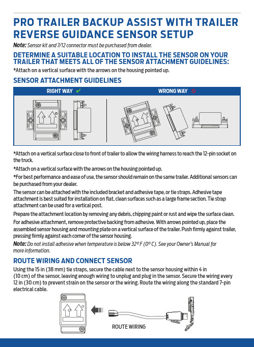
the truck.*Attach on a vertical surface with the arrows on the housing pointed up.*For best performance and ease of use, the sensor should remain on the same trailer. Additional sensors can be purchased from your dealer.The sensor can be attached with the included bracket and adhesive tape, or tie straps. Adhesive tape attachment is best suited for installation on flat, clean surfaces such as a large frame section. Tie strap attachment can be used for a vertical post.Prepare the attachment location by removing any debris, chipping paint or rust and wipe the surface clean. For adhesive attachment, remove protective backing from adhesive. With arrows pointed up, place the assembled sensor housing and mounting plate on a vertical surface of the trailer. Push firmly against trailer, pressing firmly against each corner of the sensor housing.Note: Do not install adhesive when temperature is below 32° F (0° C). See your Owner’s Manual for more information.ROUTE WIRING AND CONNECT SENSORPLACEMENT TIPS• Perform sticker placement when temperatures are above 32°F (0°C).• Clean the trailer. • Place the sticker:– On a flat, dry, horizontal surface.– Entire sticker must be visible to the camera located in the tailgate handle.– W ithin the green zone as shown below, between 4 in (10 cm) and 19 in (48 cm) from the trailer ball hitch.– Lengthwise on the trailer tongue.• Once the sticker is in place, confirm that the sticker is visible using the touchscreen.Scan the QR code for additional information about your vehicle.WARNING: Once placed, the sticker cannot be moved. Do not attempt to reuse stickers if removed.PL3J 19G217 RAford.ca 19 in 48 cm4 in 10 cm4 i n/ 10 c m19 i n/ 48 c mA-Frame Trailer Tongue Straight Trailer TongueTop ViewsYesNoP R O T R A I L E R B A C K U P A S S I S T W I T H T R A IL E R R E V E R S E G U I D A N C EF -150Q U I C K S T A R T G U I D EAugust 2022First Printing Litho in U.S.A. PL3J 19G217 RAPlease scan the QR code for additional information about your vehicle.To put QR tags to work for you, use your mobile phone’s browser or app store to download a QR tag reader. Then follow the directions to scan the QR tag and see your vehicle’s features come to life.IMPORTANTThe operation of the Pro Trailer Backup Assist ™ with Trailer Reverse Guidance system depends on how and where you place the sticker.• DO NOT ATTEMPT TO PLACE THE STICKER UNTIL YOU READ THROUGH THIS GUIDE.CARD/STICKERS POCKET (SLEEVE)Ford Customer Relationship Center 1-800-392-3673 (FORD)TDD for the hearing impaired: 7-1-1 (where offered by your telephone service provider)@FordServiceCanadaFord CustomerRelationship Centre 1-800-565-3673 (FORD) TDD for the hearing impaired: 7-1-1 (where offered by your telephone service provider)ford.ca@FordServiceCAford.ca ford.ca*IF EQUIPPEDHOW DO I USE IT?Set up this feature by following the steps in this guide. Scan the QR code on the backcover with your smartphone for more information about your vehicle.SET UP THE SYSTEM Page 3SELECT THE TRAILER TYPE Page 4POSITION YOUR VEHICLE AND TRAILER Page 5SETUP OPTIONS Page 6SETTING UP YOUR TRAILER WITH A STICKERSTICKER SETUP Page 7PLACING THE STICKER Page 8CALIBRATION Page 11FEATURE OPERATIONUSING PRO TRAILER BACKUP ASSIST Page 12FEATURE OPERATIONUSING TRAILER REVERSE GUIDANCE Page 14VIEW OPERATION Page 15HITCH ANGLE GRAPHIC Page 16TO SET UP THISFEATURE:A Pro Trailer Backup Assist control knobB TouchscreenA BRead this guide carefully and follow the instructions to place the sticker or correctly install the sensor. Doing so allows you tocomplete the one-time trailer setup process.Setup required.See page 16for operation.See page 12for operation.If you want to use thesteering wheel:A steering wheel imageAllows you to easilytrailer to go.WHAT IS PRO TRAILER BACKUP ASSIST WITHTRAILER REVERSE GUIDANCE?The Pro Trailer Backup Assist with Trailer Reverse Guidance utilizes the control knob on your instrument panel, your steering wheel and a suite of cameras totake the guesswork out of getting your trailer positioned where you want it, quickly and easily, while you're driving in reverse.Turn the knob in the direction you want the trailer to go and the system takes over the steering to get it there. This allows you to focus on monitoring themirrors and applying the brake and accelerator. Use the cameras and on-screen guidance to make even the most difficult maneuvers simple. This guide walksyou through the setup process, calibration and operation.Below is some of the added functionality that Pro Trailer Backup Assist with Trailer Reverse Guidance provides:TRAILER REVERSE STRAIGHTAUTO SPLITHITCH ANGLESTEER TRAILER12Select Add Trailer on the touchscreen.Press the center button on the knob located to the right of the steering wheel to begin settingup the system.FEATURE SETUPUse the keyboard on the touchscreen to enter the trailer name, then press the return button to confirm.SET UP THE SYSTEMThe system only works with conventional trailers. It does not work with other types, including fifth-wheel and gooseneck. Use the images to the right to help you determine your trailer type.CONVENTIONAL TRAILER EXAMPLES NON-CONVENTIONAL TRAILER EXAMPLESThe functionality of Pro Trailer Backup Assist with Trailer Reverse Guidance is not available for fifth wheel and gooseneck type trailers.SELECT THE TRAILER TYPENote: The system is designed to work with trailers that have a hitch point to center of axle or axles measurement of 6-33 ft (1.85-10.05 m). The system is designed to work with drawbars that have a license plate to hitch ball center measurement of 9-18 in (23-46 cm) when installed.34FEATURE SETUPPOSITION YOUR VEHICLE AND TRAILERRead and follow all of these steps carefully to get the best results.• Hitch the trailer to your vehicle and connect the electrical wiring harness. Check to make sure that the wiring is working.•Park your vehicle and hitched trailer on a level surface.• Make sure that the trailer and vehicle are in line with each other. You can do this by putting the transmission in drive (D) and pulling straight forward.SETUP OPTIONSYour trailer can be set up with a sticker that is provided with this guide. Follow the instructions in the next section of this guide to place your sticker and set up your trailer. For information on how to use a sensor instead of a sticker, see your Owner's Manual.ONE-TIME SETUPOnce you input your trailer’s information into the touchscreen, it is stored for easy recall. That way, when you want to use the Pro Trailer Backup Assist with Trailer Reverse Guidance system to help you back your trailer into your desired position, you can choose it from the touchscreen. You do not have to runthrough this setup again unless you want to add another trailer. You can store information for up to 10 trailers within this feature.56MAKE SURE YOU HAVE THE FOLLOWING ITEMS:For more information about your vehicle,please scan the QR code belowPlace the entire sticker in the green zone on the trailer as outlined in the diagram on page 10. The sticker is in the back cover pocket of this guide.MAKE SURE YOU GATHER THE FOLLOWING ITEMS BEFORE EXITING THE VEHICLE:PLACING THE STICKERRear view cameraSticker and sticker placement card(provided inside the back cover pocket of this guide).Tape measure (not provided).78ford.caFEATURE SETUPOUTSIDE THE VEHICLE• T ake the sticker placement card and the sticker from the back of this guide, and a tape measure, and walk back to the trailer.• P lace the sticker in the green zone as indicated in the diagram on the following page.• Confirm that the sticker is visible using the touchscreen. An assistant can remain inside the vehicle to help you do this.•P•P•U–– B•M•Place the sticker.STICKER PLACEMENT DIAGRAMNote: Place the entire sticker within the green zone. Once you place the sticker,you cannot move it. Do not attempt to reuse stickers. Use a new sticker.If you cannot find a location that meets the sticker requirements, the sensoris recommended.PLACING THE STICKER4 in10 cm4i n/10c m19 in48 cm4 in10 cm4i n/10c mA-Frame Trailer TongueStraight Trailer TongueTop ViewsYesNo19i n/48c m910Note: You can calibrate within the Pro Trailer Backup Assist or Trailer Reverse Guidance system.Find an area where you can safely drive forward and turn left or right to calibrate the system. An open parking lot is an ideal place to perform the calibration. During calibration, the system determines the hitch position and trailer length. Drive straight at approximately 2-9 mph (4-15 km/h) to align the trailer behind your vehicle.CALIBRATIONThe touchscreen provides you with instructions and tells you when the system is ready for you to turn. Turn left or right whenever you are ready and in a safe turning area. Calibrating a trailer with the sticker setup requires a straight drive and turn followed by another straight drive and turn. Longer trailers could require a 180° turn. Some trailers could require you to drive straight then turn multiple times before calibrationis complete.Too shallow of a turnC orrect 90 degree turnWhen the calibration is complete, the touchscreen displays a message that calibration is complete. The feature is now ready to use.FEATURE OPERATIONUSING PRO TRAILER BACKUP ASSIST• T o switch on the system, press the center button on the knob and watch the touchscreen. Use the touchscreen to select the connected trailer. The system detects the trailer and instructs you to shift into reverse (R) when ready.1112FEATURE OPERATIONUSING TRAILER BACKUP ASSIST• Once you have the trailer moving in the direction you want it to go, release the knob. You control the accelerator and brakes while the system steers the vehicle to keep the trailer moving straight back.• The sharper you turn the knob, the sharper the trailer turns.Note: If you attempt to accelerate beyond the system’s threshold, the system automatically limits your vehicle's speed.Note: If you use the steering wheel when using trailer backup assistance, the system turns off and a message displays in the touchscreen.• As soon as you release the knob or turn it back to the center position, the vehicle starts following the trailer's path.• Turn and hold the knob continuously for sharper vehicle and trailer turns.• CAUTION: Always keep your hand close to the control knob. You may need to quickly redirect the trailer.• You may have to use the knob to correct the trailer direction while attempting to move the trailer straight back under some conditions.Note: If you need to make a sharper you can increase the trailer angle limit in the touchscreen towing menu. Refer to your Owner'sManual for selecting the trailer angle limit setting.FEATURE OPERATIONUSING TRAILER REVERSE GUIDANCETrailer Reverse Guidance provides informational graphics and up to seven camera views to help you back up the trailer while using the steering wheel to control the trailer.If you do not set up the system, you can still use the camera views. However, the hitch angle graphic, automatic view switching and straight backup mode are not available. Complete the system setup for full functionality.USING STRAIGHT BACKUP MODE WITH TRAILER REVERSE GUIDANCE• This view is only available when you are in Trailer Reverse Guidance.• This mode shows you which way to turn your steering wheel to keep the trailer straight. A steering wheel icon is displayed on the touchscreen. A blue arrow shows you which way to turn the wheel to keep the trailer straight.•To activate this mode, select the rearview camera icon, then the straight backup mode icon.• To use Trailer Reverse Guidance, shift your vehicle into reverse (R) and press the rear view camera button on the touchscreen to expand the menu.• Select the Trailer Reverse Guidance icon on the screen. Select your trailer from the touchscreen.• The system detects the trailer and displays the hitch angle graphic.• The auto mode camera view is the default display. You can now use your steering wheel and the camera views to navigate yourtrailer into position.1314VIEW OPERATIONUse the buttons below to select the best view for backing up your vehicle and trailer. You can use these views for Pro Trailer Backup Assist or Trailer Reverse Guidance.You can select the following views by selecting the rear camera iconon the touchscreen. The view drawer displays. (View drawer shown.)*IF EQUIPPED 360 degree camera*: shows the rear camera view on the left side of the screen and the 360 degree view on the right side of the screen.Rear view camera: shows your trailer hitch or what is directly behind your vehicle.R ear split view camera*: shows a 180 degree view of area behind your vehicle.Bed camera*: shows the truck bed.Trailer AUX camera*: shows a rear view camera image of what is behind your trailer.This camera needs to be purchased and installed separately. Picture-in-picture view*: shows a main view and a secondary view when in bed camera view or trailer AUX camera view.Trailer Reverse Guidance view*: shows you a view of the sides of your vehicle and your trailer.In auto mode, this view moves as your trailer moves so that you do not have to adjust the camera as you turn. You can use the left and right arrows to see more of the driver or passenger side. Press Auto to return to automaticcamera adjustments.Takes you back to the 360 degree camera system and out of the Trailer Reverse Guidance feature.HITCH ANGLE GRAPHIC The hitch angle graphic shows you a small, top-view representation of your vehicle and trailer.This representation shows two different-colored lines:• A black line shows you where your trailer is in relation to your vehicle.• For Pro Trailer Backup Assist, the white line represents the amount the trailer turns based on knob input.• For Trailer Reverse Guidance, the white line represents the amount the trailer turns based on steering wheel position. This graphic can be seen in the normal rear view, bed camera, trailer AUX camera and Trailer Reverse Guidance camera views.151617。
福特IDS安装说明
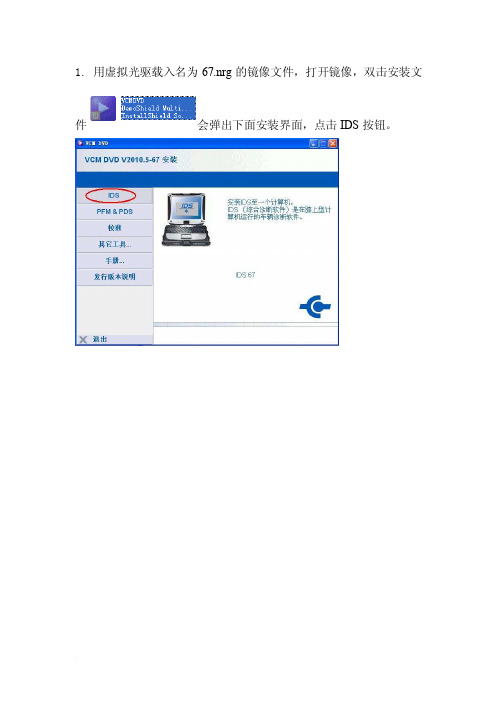
1. 用虚拟光驱载入名为67.nrg的镜像文件,打开镜像,双击安装文件会弹出下面安装界面,点击IDS按钮。
2.点击IDS按钮之后会弹出安装语言选择框,这里选择简体中文,然后点击下一步
3.接着弹出重启电脑的提示,这里点击是,这一步不会重启电脑,直接跳到下一步安装设置。
4.接着弹出下面界面,这里直接点击下一步
5.接受许可,点击下一步
6.选择安装路径,必须要满足下图所示的需要磁盘容量。
7.选择好安装路径后,点击下图所示的安装,进入安装过程。
、
8.下图为安装程序过程。
9.安装.NET插件,选择已接受许可,并点击安装。
10.安装过程,请耐心等待。
11.过程中会弹出安装校准的提示,选中我已读过内容,点击下一步
12.等待安装完成,完成后会弹出下面提示,点击重引导重启计算机。
13.
14.接着要安装校准,再打开虚拟光驱,运行,弹出安装界面。
这里要点击校准按钮,
15.弹出以下界面,直接点击下一步。
16.接着选择安装路径,注意所需空间容量。
17.接着进入校准的安装过程。
18. 等待校准安装完成之后,点击完成按钮,结束校准安装。
19.校准安装完成后,打开软件,进入下面界面有红色圆圈的发行和标定出现,则说明软件安装成功完成。
VCM IDS原厂

VCM IDS原厂VCM IDS原厂诊断设备是一款针对福特、林肯、水星及马自达等车型设计开发的汽车检测设备,Integrated Diagnostic System(IDS)是福特公司2006年推出的诊断系统,是唯一完全覆盖所有现在和将来的福特,林肯,水星以及马自达车型。
IDS替代了过去的Worldwide Diagnostic System(WDS)诊断系统,具有WDS的全部功能。
作为一个新的诊断系统,IDS能够诊断未来的车型。
IDS同时是路虎/捷豹的原厂检测仪,是授权维修站的必备诊断工具。
昌道科技提供的VCM功能:读数据流绘制数据流曲线读故障码、清故障码系统设定控制单元编程自检记录和回放可测试系统:发动机自动变速器ABS牵引力控制稳定性控制安全气囊防盗、中央门锁仪表、巡航、悬挂、空调电控转向系统IDS诊断系统VCM配置清单1xIDS诊断程序(DVD)1xVCM通讯模块1xOBDII接线1xUSB-网线英文介绍:Ford VCM IDS (VCM) is a high performance, rugged, vehicle serial communications gateway. This device provides multiple vehicle serial communication interfaces to meet the requirements of all Ford Motor Company vehicles.The VCM unit is housed in a magnesium enclosure with a tough, protective, plastic cover for the PCMCIA expansion slot which can, for example, be used for wireless LAN cards or memory expansion.The VCM device contains five LED status indicators to provide the user with a visual mode of internal VCM, vehicle, and host device (e.g. NGS Classic's T-Handle, PC, Pocket PC/PDS, and Laptop/IDS) operation.The VCM also has detachable cables for connection to industry standard high-speed host interfaces as well as to the vehicle under test.The VCM 2007.7 DVD includes both IDS (Integrated Diagnostic Software) and PDS (Portable Diagnostic Software) tools. Diagnostic coverage includes most 1996 2008 MY (produced 1995 2007) Ford, Lincoln/Mercury & Mazda vehicles.Application OverviewIntegrated Diagnostic Software (IDS) is the next generation diagnostic tool. IDS integrates WDS software modified to run on an off-the-shelf laptop with the Vehicle Communication Module (VCM) currently used in NGS and PDS, and a new Vehicle Measurement Module (VMM).Vehicle Diagnostic ConnectorsThe VCM 16-pin DLC cable is used to connect the VCM to the vehicle. The VCM and VMM connect to the laptop through the Ethernet-USB Adapter Cable (H406/H416).Interface DevicesThe interface devices that are used with this application are: 1.VCM Vehicle Communication Module: This device provides all link based functionality including: Data logger, Self test, Service Functions, Module Configuration and Programming, etc.2.VMM Vehicle Measurement Module :This device provides the following functionality: Oscilloscope, Digital Multi-Meter, Ignition System Test, Fuel System Test, and SGM.Note that the application will detect the interface device that is connected to the laptop. Indicator icons will appear at the bottom right-hand corner of the IDS screen when the VCM and/or VMM are connected.Supported languages:English, German, French, Italian, Spanish, Netherlands, Swedish, Danish, Norwegian, Portuguese, SlovakPackage includes:Vehicle communication module(VCM)16-pin DLC short cable16-pin DLC long cableIDS 4m PC Ethernet-USB host cableDVD(Ford/Mazda)DVD(Land Rover/Jugar)“VCM IDS原厂”相关信息由深圳市昌道科技有限公司编辑提供,转载请注明,谢谢。
福特竞技性能部件-M-9603-V605 85 mm冷气吸入系统 高级计算机的V6迈阿迪汽车安装说明
Techline 1-800-367-3788
Page 3 of 11
IS-1850-0360
M-9603-V605 85 mm Cold Air Kit w/Premium Cal. for V6 Mustang INSTALLATION INSTRUCTIONS
NO PART OF THIS DOCUMENT MAY BE REPRODUCED WITHOUT PRIOR AGREEMENT AND WRITTEN PERMISSION OF FORD RACING PERFORMANCE PARTS.
EQUIPMENT AND SUPPLIES REQUIRED:
• Metric ratchet / extension / socket set • Torque wrench • T-20 Torx Bit screwdriver or socket
Factory Ford shop manuals are available from Helm Publications, 1-800-782-4356
