解析单片机里的中断优先级
单片机指令的中断处理与优先级设置

单片机指令的中断处理与优先级设置中断处理是单片机系统中非常重要的一个概念,它允许在程序执行过程中暂停当前任务,转而执行其他的紧急任务。
在单片机系统中,中断按照优先级来进行处理,优先级较高的中断具有更高的执行权。
本文将探讨单片机指令的中断处理及优先级设置的相关知识。
一、中断处理的基本流程单片机中断处理的基本流程包括中断的触发、中断的响应和中断的处理。
1. 中断的触发中断的触发是指引起中断的事件发生,例如外部输入的信号改变或者定时器计数器溢出等。
当发生中断触发事件时,单片机会检测到该事件,并决定是否触发相关的中断。
2. 中断的响应中断的响应是指单片机在发生中断触发事件后,立即停止当前任务的执行,保存当前任务的状态,并转而执行中断服务程序。
为了保证中断处理的正确性,单片机需要在中断响应之前关闭其他中断的触发,以保证只有最高优先级的中断得以响应。
3. 中断的处理中断的处理指单片机执行对应中断的服务程序。
中断服务程序是一个独立的子程序,用于处理中断触发事件。
根据具体的应用需求,中断服务程序可以进行一系列的操作,例如读写寄存器、处理数据、发送接收数据等。
处理完成后,需要恢复原来的状态,并返回到原来的任务继续执行。
二、中断优先级设置为了合理地处理多个中断,单片机中提供了中断优先级设置的功能。
不同的中断可以设置不同的优先级,以确保高优先级的中断能够及时得到处理。
1. 优先级的概念优先级是用来区分不同中断响应顺序的标志。
单片机一般会提供多个中断请求引脚,每个引脚连接一个外设设备。
设置不同中断的优先级可以根据外设设备的重要性和响应要求来确定。
2. 优先级的设置方法在单片机中,一般都会提供中断优先级设置的相关控制位或寄存器。
我们可以通过设置这些位或寄存器来对中断进行优先级的设置。
具体的设置方法可以根据不同的单片机型号来确定,一般会提供相应的中断控制寄存器或指令用于设置中断的优先级。
一般来说,越低的优先级对应的中断响应越晚。
实验四单片机中断优先级实验

实验四单片机中断优先级实验一、实验目的1.理解AT89C51单片机中断优先级和优先权。
2.用PROTEUS设计、仿真基于AT89C51单片机的中断优先级实验。
3.掌握中断编程。
4.掌握发光二极管的控制方法。
二、实验要求单片机主程序控制P0口数码管循环显示0~8;外中断(INT0)、外中断(INT1)发生时分别在P2、P1口依次显示0~8;INT1为高优先级,INT0为低优先级。
三、电路设计1.从①②RES、③④CAP、CAP-ELEC:电容、电解电容;⑤CRYSTAL:晶振;⑥BUTTON:按钮。
2.放置元器件3.放置电源和地4.连线5.元器件属性设置6.电气检测四、源程序设计、生成目标代码文件1.流程图2.源程序设计通过菜单“source→Add/Remove Source Files…”新建源程序文件:。
通过菜单“source→”,打开PROTEUS提供的文本编辑器SRCEDIT,在其中编辑源程序。
程序编辑好后,单击按钮存入文件。
3.源程序编译汇编、生成目标代码文件通过菜单“source→Build All”编译汇编源程序,生成目标代码文件。
若编译失败,可对程序进行修改调试直至汇编成功。
五、PROTEUS仿真1.加载目标代码文件2.全速仿真单击按钮,启动仿真。
(1)低优先级INT0中断主程序:当主程序运行时,单片机控制与P0口相接的数码管循环显示1~8;而P1、P2口的数码管不显示。
当前主程序控制P0口显示“8”的时刻单击“低优先级输入”按钮,触发INT0如图所示,INT0服务程序控制P2口依次显示1~8,当前显示“2”。
(2)高优先级INT1中断低优先级INT0;在上一步的基础上,即主程序被INT0中断在P0口输出“8”,而在INT0服务程序在P2口输出“2”的时刻,单击“高优先级输入”按钮,触发高优先级INT1,所在INT0被中断在显示“2”,INT1服务程序控制P1口依次显示1~8。
3.仿真调试六、思考题:1.说明单片机中共有哪几种中断,它们的默认优先级是什么2.怎样修改中断优先级例如在本实验中要使TIMER1成为优先级最高的中断,该怎么处理。
51单片机的中断优先级及中断嵌套

51 单片机的中断优先级及中断嵌套
说最基本的,老的51 单片机(80C51 系列)有5 个中断源,2 个优先级,
可以实现二级中断服务嵌套。
现在很多扩展的51 单片机已经有4 个优先级(或更多)和更多的中断源了。
在说到中断之前,我先来定义一下优先级,明白了什幺是优先级,后面的阐述就容易明白了。
实际上很多人都是混淆了优先级的含义,所以才觉得糊里糊涂。
中断的优先级有两个:查询优先级和执行优先级。
什幺是查询优级呢?我们从datasheet 或书上看到的默认(IP 寄存器不做设
置,上电复位后为00H)的优先级:
外部中断0 > 定时/计数器0 > 外部中断1 > 定时/计数器1 > 串行中断
或int0,timer0,int1,timer1,serial port 或INT0、T0、INT1、T1、UART
或PX0>PT0>PX1>PT1>PS>......
其实都是查询优级。
首先查询优先级是不可以更改和设置的。
这是一个中断优先权排队的问题。
是指多个中断源同时产生中断信号时,中断仲裁器选择对哪个中断源优先处理的顺序。
而这与是否发生中断服务程序的嵌套毫不。
单片机中的中断系统设计与应用实例
单片机中的中断系统设计与应用实例中断是单片机系统中一种重要的实时任务处理机制,用于处理紧急事件或高优先级任务。
中断系统的设计和应用在单片机开发中是至关重要的一部分。
本文将介绍单片机中的中断系统设计原则,并提供一个实际应用的案例。
一、中断系统设计原则1. 中断优先级排序:在设计中断系统时,应根据任务的重要性和紧急性为每个中断设置优先级。
高优先级中断可以打断低优先级中断的执行,确保紧急任务的及时处理。
2. 中断服务程序:每个中断都需要编写相应的中断服务程序(ISR)。
ISR负责处理中断事件,包括保存当前执行状态、中断请求的判定、中断相关的处理操作等。
3. 中断向量表:中断向量表是一个存储中断向量地址的数据表。
当发生中断时,单片机会根据中断号在中断向量表中查找对应的中断服务程序的入口地址,从而完成中断服务的调用。
4. 中断屏蔽和使能:单片机的中断系统通常提供屏蔽和使能中断的机制。
中断屏蔽允许开发者在需要时暂时关闭特定中断,以避免干扰当前任务的执行。
而使能中断则允许开发者在适当的时候开启相应的中断。
二、中断系统应用实例:采集温度数据假设我们需要设计一个温度采集系统,通过单片机实时采集并处理温度数据。
当温度超过一定阈值时,系统要发出警报。
这种情况下,我们可以使用中断系统来监听温度传感器并实现相应的处理。
首先,我们需要编写一个中断服务程序来处理温度中断。
在这个中断服务程序中,我们需要获取温度传感器的数值并与阈值进行比较。
如果超过阈值,则触发警报。
接下来,我们需要配置单片机的中断向量表,并设置中断优先级。
由于温度采集任务是紧急任务,我们可以将温度中断设置为最高优先级,以确保及时响应。
然后,我们需要配置温度传感器的中断输出引脚,并连接到单片机的中断引脚。
当温度超过阈值时,传感器会通过中断引脚向单片机发送中断请求,这将触发中断系统的工作。
最后,我们可以在主函数中启用中断,并进行其他的温度采集和处理操作。
当温度中断触发时,单片机将自动跳转到温度中断服务程序进行处理,完成相应的警报操作。
51单片机中断总结
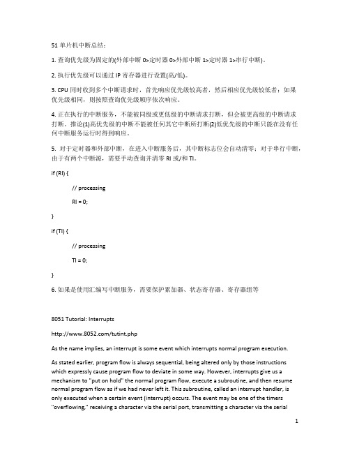
51单片机中断总结:1. 查询优先级为固定的(外部中断0>定时器0>外部中断1>定时器1>串行中断)。
2. 执行优先级可以通过IP寄存器进行设置(高/低)。
3. CPU同时收到多个中断请求时,首先响应优先级较高者,然后相应优先级较低者;如果优先级相同,则按照查询优先级顺序依次响应。
4. 正在执行的中断服务,不能被同级或更低级的中断请求打断,但会被更高级的中断请求打断。
推论(1)高优先级的中断不能被任何其它中断所打断(2)低优先级的中断只能在没有任何中断服务运行时得到响应。
5. 对于定时器和外部中断,在进入中断服务后,其中断标志位会自动清零;对于串行中断,由于有两个中断源,需要手动查询并清零RI或/和TI。
if (RI) {// processingRI = 0;}if (TI) {// processingTI = 0;}6. 如果是使用汇编写中断服务,需要保护累加器、状态寄存器、寄存器组等8051 Tutorial: Interrupts/tutint.phpAs the name implies, an interrupt is some event which interrupts normal program execution.As stated earlier, program flow is always sequential, being altered only by those instructions which expressly cause program flow to deviate in some way. However, interrupts give us a mechanism to "put on hold" the normal program flow, execute a subroutine, and then resume normal program flow as if we had never left it. This subroutine, called an interrupt handler, is only executed when a certain event (interrupt) occurs. The event may be one of the timers "overflowing," receiving a character via the serial port, transmitting a character via the serialport, or one of two "external events." The 8051 may be configured so that when any of these events occur the main program is temporarily suspended and control passed to a special section of code which presumably would execute some function related to the event that occured. Once complete, control would be returned to the original program. The main program never even knows it was interrupted.The ability to interrupt normal program execution when certain events occur makes it much easier and much more efficient to handle certain conditions. If it were not for interrupts we would have to manually check in our main program whether the timers had overflown, whether we had received another character via the serial port, or if some external event had occured. Besides making the main program ugly and hard to read, such a situation would make our program inefficient since wed be burning precious "instruction cycles" checking for events that usually dont happen.For example, lets say we have a large 16k program executing many subroutines performing many tasks. Lets also suppose that we want our program to automatically toggle the P3.0 port every time timer 0 overflows. The code to do this isnt too difficult:JNB TF0,SKIP_TOGGLECPL P3.0CLR TF0SKIP_TOGGLE: ...Since the TF0 flag is set whenever timer 0 overflows, the above code will toggle P3.0 every time timer 0 overflows. This accomplishes what we want, but is inefficient. The JNB instruction consumes 2 instruction cycles to determine that the flag is not set and jump over the unnecessary code. In the event that timer 0 overflows, the CPL and CLR instruction require 2 instruction cycles to execute. To make the math easy, lets say the rest of the code in the program requires 98 instruction cycles. Thus, in total, our code consumes 100 instruction cycles (98 instruction cycles plus the 2 that are executed every iteration to determine whether or not timer 0 has overflowed). If were in 16-bit timer mode, timer 0 will overflow every 65,536 machine cycles. In that time we would have performed 655 JNB tests for a total of 1310 instruction cycles, plus another 2 instruction cycles to perform the code. So to achieve our goal weve spent 1312 instruction cycles. So 2.002% of our time is being spent just checking when to toggle P3.0. And our code is ugly because we have to make that check every iteration of our main program loop.Luckily, this isnt necessary. Interrupts let us forget about checking for the condition. The microcontroller itself will check for the condition automatically and when the condition is met will jump to a subroutine (called an interrupt handler), execute the code, then return. In this case, our subroutine would be nothing more than:CPL P3.0RETIFirst, youll notice the CLR TF0 command has disappeared. Thats because when the 8051 executes our "timer 0 interrupt routine," it automatically clears the TF0 flag. Youll also notice that instead of a normal RET instruction we have a RETI instruction. The RETI instruction does the same thing as a RET instruction, but tells the 8051 that an interrupt routine has finished. You must always end your interrupt handlers with RETI.Thus, every 65536 instruction cycles we execute the CPL instruction and the RETI instruction. Those two instructions together require 3 instruction cycles, and weve accomplished the same goal as the first example that required 1312 instruction cycles. As far as the toggling of P3.0 goes, our code is 437 times more efficient! Not to mention its much easier to read and understand because we dont have to remember to always check for the timer 0 flag in our main program. We just setup the interrupt and forget about it, secure in the knowledge that the 8051 will execute our code whenever its necessary.The same idea applies to receiving data via the serial port. One way to do it is to continuously check the status of the RI flag in an endless loop. Or we could check the RI flag as part of a larger program loop. However, in the latter case we run the risk of missing characters--what happens if a character is received right after we do the check, the rest of our program executes, and before we even check RI a second character has come in. We will lose the first character. With interrupts, the 8051 will put the main program "on hold" and call our special routine to handle the reception of a character. Thus, we neither have to put an ugly check in our main code nor will we lose characters.What Events Can Trigger Interrupts, and where do they go?We can configure the 8051 so that any of the following events will cause an interrupt:Timer 0 Overflow.Timer 1 Overflow.Reception/Transmission of Serial Character.External Event 0.External Event 1.In other words, we can configure the 8051 so that when Timer 0 Overflows or when a character is sent/received, the appropriate interrupt handler routines are called.Obviously we need to be able to distinguish between various interrupts and executing different code depending on what interrupt was triggered. This is accomplished by jumping to a fixed address when a given interrupt occurs.Interrupt Flag Interrupt Handler AddressExternal 0 IE0 0003hTimer 0 TF0 000BhExternal 1 IE1 0013hTimer 1 TF1 001BhSerial RI/TI 0023hBy consulting the above chart we see that whenever Timer 0 overflows (i.e., the TF0 bit is set), the main program will be temporarily suspended and control will jump to 000BH. It is assumed that we have code at address 000BH that handles the situation of Timer 0 overflowing.Setting Up InterruptsBy default at powerup, all interrupts are disabled. This means that even if, for example, the TF0 bit is set, the 8051 will not execute the interrupt. Your program must specifically tell the 8051 that it wishes to enable interrupts and specifically which interrupts it wishes to enable.Your program may enable and disable interrupts by modifying the IE SFR (A8h):Bit Name Bit Address Explanation of Function7 EA AFh Global Interrupt Enable/Disable6 - AEh Undefined5 - ADh Undefined4 ES ACh Enable Serial Interrupt3 ET1 ABh Enable Timer 1 Interrupt2 EX1 AAh Enable External 1 Interrupt1 ET0 A9h Enable Timer 0 Interrupt0 EX0 A8h Enable External 0 InterruptAs you can see, each of the 8051s interrupts has its own bit in the IE SFR. You enable a given interrupt by setting the corresponding bit. For example, if you wish to enable Timer 1 Interrupt, you would execute either:MOV IE,#08horSETB ET1Both of the above instructions set bit 3 of IE, thus enabling Timer 1 Interrupt. Once Timer 1 Interrupt is enabled, whenever the TF1 bit is set, the 8051 will automatically put "on hold" the main program and execute the Timer 1 Interrupt Handler at address 001Bh.However, before Timer 1 Interrupt (or any other interrupt) is truly enabled, you must also set bit 7 of IE. Bit 7, the Global Interupt Enable/Disable, enables or disables all interrupts simultaneously. That is to say, if bit 7 is cleared then no interrupts will occur, even if all the other bits of IE are set. Setting bit 7 will enable all the interrupts that have been selected by setting other bits in IE. This is useful in program execution if you have time-critical code that needs to execute. In this case, you may need the code to execute from start to finish without any interrupt getting in the way. To accomplish this you can simply clear bit 7 of IE (CLR EA) and then set it after your time-criticial code is done.So, to sum up what has been stated in this section, to enable the Timer 1 Interrupt the most common approach is to execute the following two instructions:SETB ET1SETB EAThereafter, the Timer 1 Interrupt Handler at 01Bh will automatically be called whenever the TF1 bit is set (upon Timer 1 overflow).Polling SequenceThe 8051 automatically evaluates whether an interrupt should occur after every instruction. When checking for interrupt conditions, it checks them in the following order:External 0 InterruptTimer 0 InterruptExternal 1 InterruptTimer 1 InterruptSerial InterruptThis means that if a Serial Interrupt occurs at the exact same instant that an External 0 Interrupt occurs, the External 0 Interrupt will be executed first and the Serial Interrupt will be executed once the External 0 Interrupt has completed.Interrupt PrioritiesThe 8051 offers two levels of interrupt priority: high and low. By using interrupt priorities you may assign higher priority to certain interrupt conditions.For example, you may have enabled Timer 1 Interrupt which is automatically called every time Timer 1 overflows. Additionally, you may have enabled the Serial Interrupt which is called every time a character is received via the serial port. However, you may consider that receiving a character is much more important than the timer interrupt. In this case, if Timer 1 Interrupt is already executing you may wish that the serial interrupt itself interrupts the Timer 1 Interrupt. When the serial interrupt is complete, control passes back to Timer 1 Interrupt and finally back to the main program. You may accomplish this by assigning a high priority to the Serial Interrupt and a low priority to the Timer 1 Interrupt.Interrupt priorities are controlled by the IP SFR (B8h). The IP SFR has the following format:Bit Name Bit Address Explanation of Function7 - - Undefined6 - - Undefined5 - - Undefined4 PS BCh Serial Interrupt Priority3 PT1 BBh Timer 1 Interrupt Priority2 PX1 BAh External 1 Interrupt Priority1 PT0 B9h Timer 0 Interrupt Priority0 PX0 B8h External 0 Interrupt PriorityWhen considering interrupt priorities, the following rules apply:Nothing can interrupt a high-priority interrupt--not even another high priority interrupt.A high-priority interrupt may interrupt a low-priority interrupt.A low-priority interrupt may only occur if no other interrupt is already executing.If two interrupts occur at the same time, the interrupt with higher priority will execute first. If both interrupts are of the same priority the interrupt which is serviced first by polling sequence will be executed first.What Happens When an Interrupt Occurs?When an interrupt is triggered, the following actions are taken automatically by the microcontroller:The current Program Counter is saved on the stack, low-byte first.Interrupts of the same and lower priority are blocked.In the case of Timer and External interrupts, the corresponding interrupt flag is cleared.Program execution transfers to the corresponding interrupt handler vector address.The Interrupt Handler Routine executes.Take special note of the third step: If the interrupt being handled is a Timer or External interrupt, the microcontroller automatically clears the interrupt flag before passing control to your interrupt handler routine. This means it is not necessary that you clear the bit in your code.What Happens When an Interrupt Ends?An interrupt ends when your program executes the RETI (Return from Interrupt) instruction. When the RETI instruction is executed the following actions are taken by the microcontroller:Two bytes are popped off the stack into the Program Counter to restore normal program execution.Interrupt status is restored to its pre-interrupt status.Serial InterruptsSerial Interrupts are slightly different than the rest of the interrupts. This is due to the fact that there are two interrupt flags: RI and TI. If either flag is set, a serial interrupt is triggered. As you will recall from the section on the serial port, the RI bit is set when a byte is received by the serial port and the TI bit is set when a byte has been sent.This means that when your serial interrupt is executed, it may have been triggered because the RI flag was set or because the TI flag was set--or because both flags were set. Thus, your routine must check the status of these flags to determine what action is appropriate. Also, since the 8051 does not automatically clear the RI and TI flags you must clear these bits in your interrupt handler.A brief code example is in order:INT_SERIAL: JNB RI,CHECK_TI ;If the RI flag is not set, we jump to check TIMOV A,SBUF ;If we got to this line, its because the RI bit *was* setCLR RI ;Clear the RI bit after weve processed itCHECK_TI: JNB TI,EXIT_INT ;If the TI flag is not set, we jump to the exit pointCLR TI ;Clear the TI bit before we send another characterMOV SBUF,#A ;Send another character to the serial portEXIT_INT: RETIAs you can see, our code checks the status of both interrupts flags. If both flags were set, both sections of code will be executed. Also note that each section of code clears its corresponding interrupt flag. If you forget to clear the interrupt bits, the serial interrupt will be executed over and over until you clear the bit. Thus it is very important that you always clear the interrupt flags in a serial interrupt.Important Interrupt Consideration: Register ProtectionOne very important rule applies to all interrupt handlers: Interrupts must leave the processor in the same state as it was in when the interrupt initiated.Remember, the idea behind interrupts is that the main program isnt aware that they are executing in the "background." However, consider the following code:CLR C ;Clear carryMOV A,#25h ;Load the accumulator with 25hADDC A,#10h ;Add 10h, with carryAfter the above three instructions are executed, the accumulator will contain a value of 35h.But what would happen if right after the MOV instruction an interrupt occured. During this interrupt, the carry bit was set and the value of the accumulator was changed to 40h. When the interrupt finished and control was passed back to the main program, the ADDC would add 10h to 40h, and additionally add an additional 1h because the carry bit is set. In this case, the accumulator will contain the value 51h at the end of execution.In this case, the main program has seemingly calculated the wrong answer. How can 25h + 10h yield 51h as a result? It doesnt make sense. A programmer that was unfamiliar with interrupts would be convinced that the microcontroller was damaged in some way, provoking problems with mathematical calculations.What has happened, in reality, is the interrupt did not protect the registers it used. Restated: An interrupt must leave the processor in the same state as it was in when the interrupt initiated.What does this mean? It means if your interrupt uses the accumulator, it must insure that the value of the accumulator is the same at the end of the interrupt as it was at the beginning. This is generally accomplished with a PUSH and POP sequence. For example:PUSH ACCPUSH PSWMOV A,#0FFhADD A,#02hPOP PSWPOP ACCThe guts of the interrupt is the MOV instruction and the ADD instruction. However, these two instructions modify the Accumulator (the MOV instruction) and also modify the value of the carry bit (the ADD instruction will cause the carry bit to be set). Since an interrupt routine must guarantee that the registers remain unchanged by the routine, the routine pushes the original values onto the stack using the PUSH instruction. It is then free to use the registers it protected to its hearts content. Once the interrupt has finished its task, it pops the original values back into the registers. When the interrupt exits, the main program will never know the difference because the registers are exactly the same as they were before the interrupt executed.In general, your interrupt routine must protect the following registers:PSWDPTR (DPH/DPL)PSWACCBRegisters R0-R7Remember that PSW consists of many individual bits that are set by various 8051 instructions. Unless you are absolutely sure of what you are doing and have a complete understanding of what instructions set what bits, it is generally a good idea to always protect PSW by pushing and popping it off the stack at the beginning and end of your interrupts.Note also that most assemblers (in fact, ALL assemblers that I know of) will not allow you to execute the instruction:PUSH R0This is due to the fact that depending on which register bank is selected, R0 may refer to either internal ram address 00h, 08h, 10h, or 18h. R0, in and of itself, is not a valid memory address that the PUSH and POP instructions can use.Thus, if you are using any "R" register in your interrupt routine, you will have to push that registers absolute address onto the stack instead of just saying PUSH R0. For example, instead of PUSH R0 you would execute:PUSH 00hOf course, this only works if youve selected the default register set. If you are using an alternate register set, you must PUSH the address which corresponds to the register you are using.Common Problems with InterruptsInterrupts are a very powerful tool available to the 8051 developer, but when used incorrectly they can be a source of a huge number of debugging hours. Errors in interrupt routines are often very difficult to diagnose and correct.If you are using interrupts and your program is crashing or does not seem to be performing as you would expect, always review the following interrupt-related issues:Register Protection: Make sure you are protecting all your registers, as explained above. If you forget to protect a register that your main program is using, very strange results may occur. In our example above we saw how failure to protect registers caused the main program to apparently calculate that 25h + 10h = 51h. If you witness problems with registers changing values unexpectedly or operations producing "incorrect" values, it is very likely that you've forgotten to protect registers. ALWAYS PROTECT YOUR REGISTERS.Forgetting to restore protected values: Another common error is to push registers onto the stack to protect them, and then forget to pop them off the stack before exiting the interrupt. For example, you may push ACC, B, and PSW onto the stack in order to protect them and subsequently pop only ACC and PSW off the stack before exiting. In this case, since you forgot to restore the value of "B", an extra value remains on the stack. When you execute the RETI instruction the 8051 will use that value as the return address instead of the correct value. In this case, your program will almost certainly crash. ALWAYS MAKE SURE YOU POP THE SAME NUMBER OF VALUES OFF THE STACK AS YOU PUSHED ONTO IT.Using RET instead of RETI: Remember that interrupts are always terminated with the RETI instruction. It is easy to inadvertantly use the RET instruction instead. However, the RETinstruction will not end your interrupt. Usually, using a RET instead of a RETI will cause the illusion of your main program running normally, but your interrupt will only be executed once. If it appears that your interrupt mysteriously stops executing, verify that you are exiting with RETI.11。
单片机延时函数和定时器中断的优先级

单片机延时函数和定时器中断的优先级下载提示:该文档是本店铺精心编制而成的,希望大家下载后,能够帮助大家解决实际问题。
文档下载后可定制修改,请根据实际需要进行调整和使用,谢谢!本店铺为大家提供各种类型的实用资料,如教育随笔、日记赏析、句子摘抄、古诗大全、经典美文、话题作文、工作总结、词语解析、文案摘录、其他资料等等,想了解不同资料格式和写法,敬请关注!Download tips: This document is carefully compiled by this editor. I hope that after you download it, it can help you solve practical problems. The document can be customized and modified after downloading, please adjust and use it according to actual needs, thank you! In addition, this shop provides you with various types of practical materials, such as educational essays, diary appreciation, sentence excerpts, ancient poems, classic articles, topic composition, work summary, word parsing, copy excerpts, other materials and so on, want to know different data formats and writing methods, please pay attention!1. 引言在单片机编程中,延时函数和定时器中断是常用的时间控制方法。
c51语言处理单片机的中断是由专门的中断函数来处理的
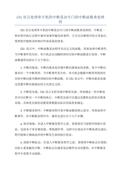
c51语言处理单片机的中断是由专门的中断函数来处理的C51语言处理单片机的中断是由专门的中断函数来处理的。
中断是一种在程序执行过程中被外部事件触发的事件,它可以打断程序的正常执行,使得程序能够及时响应外部设备的请求。
C51语言中,中断函数是由程序员自定义的函数,用来处理中断事件。
当中断事件发生时,单片机会自动跳转到对应的中断函数进行处理。
中断函数通常包括以下几个部分:1.中断向量表:中断向量表是存储中断向量地址的表格。
每个中断向量对应一个中断类型,当中断事件发生时,单片机会根据中断类型找到对应的中断向量并跳转到相应的中断函数。
在C51语言中,中断向量表是通过设置中断向量地址的方式来定义的。
2.中断优先级:C51语言支持多级中断优先级,用来确定一些中断是否可以打断另一个中断的执行。
中断优先级可以通过设置特定的寄存器来实现,具体优先级的设置需要根据实际应用场景来确定。
3.中断服务程序:中断服务程序是中断函数的核心部分,用来处理中断事件。
在中断服务程序中,通常会进行以下几个步骤:a.保存现场:在进入中断服务程序之前,需要保存当前程序的执行状态,包括各个寄存器的值、堆栈指针等。
这样可以保证在中断处理完成后,程序能够正确地返回到中断发生前的执行状态。
b.清除中断标志:在进入中断服务程序之前,需要将中断标志位清除,以防止重复触发中断。
中断标志位通常是由硬件自动设置的,在中断服务程序中需要手动清除。
c.执行中断处理逻辑:在中断服务程序中,可以编写相应的逻辑代码来处理中断事件。
这可以包括读取外部设备的数据、进行数据处理、发送数据等。
中断服务程序中的代码需要尽量简洁高效,以确保及时响应外部事件。
d.恢复现场:在中断服务程序执行完成后,需要恢复之前保存的执行状态,包括恢复各个寄存器的值、堆栈指针等。
这样可以保证程序能够正确地返回到中断发生前的执行状态。
4.中断返回指令:在中断服务程序执行完成后,需要使用特定的指令来返回到主程序的执行位置。
51单片机中的中断优先级总结
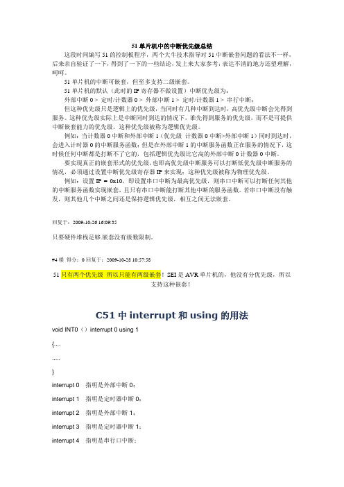
51单片机中的中断优先级总结这段时间编写51的控制板程序,两个大牛技术指导对51中断嵌套问题的看法不一样,后来亲自验证了一下,得到了一下的一些结论,发上来大家参考,表达不清的地方还望理解,呵呵。
51单片机的中断可嵌套,但至多支持二级嵌套。
51单片机的默认(此时的IP寄存器不做设置)中断优先级为:外部中断0 > 定时/计数器0 > 外部中断1 > 定时/计数器1 > 串行中断;但这种优先级只是逻辑上的优先级,当同时有几种中断到达时,高优先级中断会先得到服务。
这种优先级实际上是中断同时到达的情况下,谁先得到服务的优先级,而不是可提供中断嵌套能力的优先级。
这种优先级被称为逻辑优先级。
例如:当计数器0中断和外部中断1(优先级计数器0中断>外部中断1)同时到达时,会进入计时器0的中断服务函数;但是在外部中断1的中断服务函数正在服务的情况下,这时候任何中断都是打断不了它的,包括逻辑优先级比它高的外部中断0计数器0中断。
要实现真正的嵌套形式的优先级,也即高优先级中断服务可以打断低优先级中断服务的情况,必须通过设置中断优先级寄存器IP来实现;这种优先级被称为物理优先级。
例如:设置IP = 0x10,即设置串口中断为最高优先级,则串口中断可以打断任何其他的中断服务函数实现嵌套,且只有串口中断能打断其他中断的服务函数。
若串口中断没有触发,则其他几个中断之间还是保持逻辑优先级,相互之间无法嵌套。
回复于:2009-10-26 16:09:35只要硬件堆栈足够.嵌套没有级数限制。
#4楼得分:0回复于:2009-10-28 10:57:5851只有两个优先级所以只能有两级嵌套!SEI是AVR单片机的,他没有分优先级,所以支持这种嵌套!C51中interrupt和using的用法void INT0()interrupt 0 using 1{.........}interrupt 0 指明是外部中断0;interrupt 1 指明是定时器中断0;interrupt 2 指明是外部中断1;interrupt 3 指明是定时器中断1;interrupt 4 指明是串行口中断;using 0 是第0组寄存器;using 1 是第1组寄存器;using 2 是第2组寄存器;using 3 是第3组寄存器;51单片机内的寄存器是R0--R7(不是R0-R3)R0-R7在数据存储器里的实际地址是由特殊功能寄存器PSW里的RS1、RS0位决定的。
详解单片机里面的中断优先级

详解单片机里面的中断优先级
中断优先级的内容,大家先通过我的介绍大概了解一下即可,后边实际应用的时候我们再详细理解。
在讲中断产生背景的时候,我们仅仅讲了看电视和烧水的例子,但是实际生活当中还有更复杂的,比如我正在看电视,这个时候来电话了,我要进入接电话的“中断”程序当中去,就在接电话的同时,听到了水开的声音,水开的“中断”也发生了,我们就必须要放下手上的电话,先把煤气关掉,然后再回来听电话,最后听完了电话再看电视,这里就产生了一个优先级的问题。
还有一种情况,我们在看电视的时候,这个时候听到水开的声音,水开的“中断”发生了,我们要进入关煤气的“中断”程序当中,而在关煤气的同时,电话声音响了,而这个时候,我们的处理方式是先把煤气关闭,再去接听电话,最后再看电视。
从这两个过程中,我们可以得到一个结论,就是最最紧急的事情,一旦发生后,我们不管当时处在哪个“程序”当中,我们必须先去处理最最紧急的事情,处理完毕后再去解决其它事情。
在我们的单片机程序当中有时候也是这样的,有一般紧急的中断,有特别紧急的中断,这取决于具体的系统设计,。
单片机中断问题总结
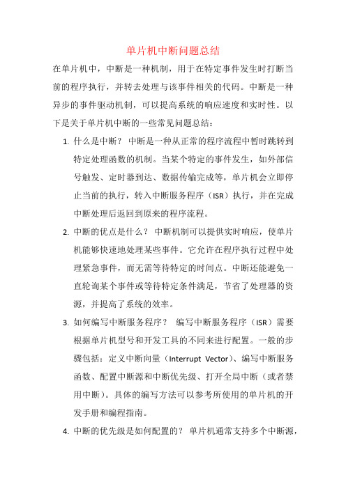
单片机中断问题总结在单片机中,中断是一种机制,用于在特定事件发生时打断当前的程序执行,并转去处理与该事件相关的代码。
中断是一种异步的事件驱动机制,可以提高系统的响应速度和实时性。
以下是关于单片机中断的一些常见问题总结:1.什么是中断?中断是一种从正常的程序流程中暂时跳转到特定处理函数的机制。
当某个特定的事件发生,如外部信号触发、定时器到达、数据传输完成等,单片机会立即停止当前的执行,转入中断服务程序(ISR)执行,并在完成中断处理后返回到原来的程序流程。
2.中断的优点是什么?中断机制可以提供实时响应,使单片机能够快速地处理某些事件。
它允许在程序执行过程中处理紧急事件,而无需等待特定的时间点。
中断还能避免一直轮询某个事件或等待特定条件满足,节省了处理器的资源,并提高了系统的效率。
3.如何编写中断服务程序?编写中断服务程序(ISR)需要根据单片机型号和开发工具的不同来进行配置。
一般的步骤包括:定义中断向量(Interrupt Vector)、编写中断服务函数、配置中断源和中断优先级、打开全局中断(或者禁用中断)。
具体的编写方法可以参考所使用的单片机的开发手册和编程指南。
4.中断的优先级是如何配置的?单片机通常支持多个中断源,并且可以根据需要为每个中断源分配优先级。
中断的优先级配置取决于具体的单片机型号和芯片架构,可以通过相关的寄存器设置或软件配置来实现。
5.中断可能带来哪些问题?在设计中断服务程序时,需要注意以下一些问题:中断嵌套的处理、共享的资源竞争、中断延迟和消耗的处理时间等。
合理的设计和编码可以避免这些问题,并确保中断机制的稳定和可靠性。
总之,在单片机应用中,中断是一种重要的机制,用于处理及时和紧急的事件。
了解中断的工作原理、编写和配置中断服务程序,并注意中断可能引发的问题,有助于提高单片机系统的效率和功能。
单片机中断的概念

单片机中断的概念单片机中断(Interrupt)是指当单片机正在执行某个任务时,突然出现了某个特定事件,该事件具有比当前任务更高的优先级,需要立即被处理。
在这种情况下,单片机会中断正在执行的任务,转而处理该事件的相关程序,待处理完毕后再返回原任务继续执行。
单片机中断的概念及其使用可以极大地提高系统的响应速度和处理效率。
一、中断的基本原理单片机中断的基本原理是通过外部设备或者内部事件触发中断请求,使得单片机暂停当前正在执行的任务,转而执行中断服务程序,处理相关事件。
单片机在执行相关中断服务程序后,会自动返回到原来的任务继续执行。
二、中断的分类根据中断的来源和触发方式,中断可以分为外部中断和内部中断两种类型。
1. 外部中断:外部中断是指通过外部引脚(例如:中断引脚)触发的中断。
当外部引脚发生状态变化时,会产生中断请求,单片机会立即响应并执行中断服务程序。
外部中断适用于需要实时响应外部事件的场景,如按键输入、外部传感器触发等。
2. 内部中断:内部中断是指通过单片机内部事件触发的中断。
内部事件可以是定时器溢出、串口接收数据等。
内部中断常用于定时任务、通信处理等场景。
三、中断的优点单片机中断具有以下几个优点:1. 响应快速:当发生中断事件时,单片机可以立即停止执行当前任务,转而执行中断服务程序,从而实现实时响应。
这种响应速度是通过轮询方式无法达到的。
2. 处理高效:中断服务程序可以针对特定事件进行处理,提高了处理效率。
相比轮询方式,单片机无需逐个检测事件是否发生,可以直接处理发生中断的事件。
3. 灵活性强:中断可以根据事件的优先级和紧急程度进行处理,可以根据具体需求设定中断优先级,提高了系统的灵活性和可控性。
4. 节省能源:在空闲状态下,单片机可以进入低功耗模式,当有中断事件发生时再被唤醒,降低功耗,延长系统续航时间。
四、中断的使用步骤单片机中断的使用步骤如下:1. 配置中断源:根据需要,选择外部中断引脚,或者开启内部中断功能。
中断优先级及原理图
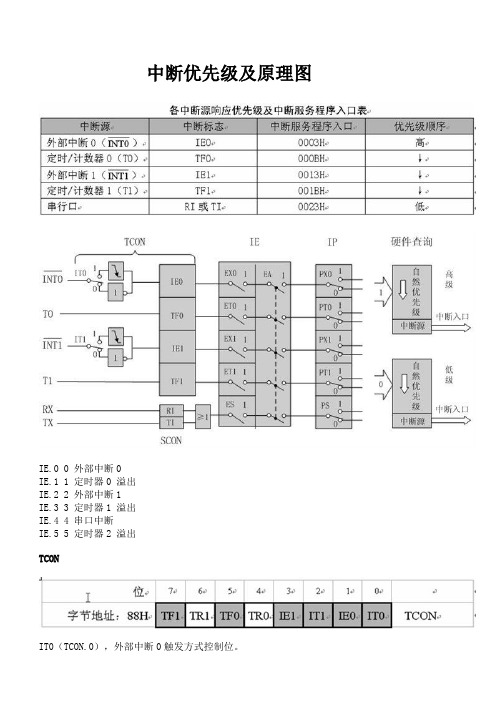
中断优先级及原理图IE.0 0 外部中断0IE.1 1 定时器0 溢出IE.2 2 外部中断1IE.3 3 定时器1 溢出IE.4 4 串口中断IE.5 5 定时器2 溢出TCONIT0(TCON.0),外部中断0触发方式控制位。
当IT0=0时,为电平触发方式。
当IT0=1时,为边沿触发方式(下降沿有效)。
IE0(TCON.1),外部中断0中断请求标志位。
IT1(TCON.2),外部中断1触发方式控制位。
IE1(TCON.3),外部中断1中断请求标志位。
TF0(TCON.5),定时/计数器T0溢出中断请求标志位。
TF1(TCON.7),定时/计数器T1溢出中断请求标志位。
SCONRI(SCON.0),串行口接收中断标志位。
当允许串行口接收数据时,每接收完一个串行帧,由硬件置位RI。
注意,RI必须由软件清除。
TI(SCON.1),串行口发送中断标志位。
当CPU将一个发送数据写入串行口发送缓冲器时,就启动了发送过程。
每发送完一个串行帧,由硬件置位TI。
CPU响应中断时,不能自动清除TI,TI必须由软件清除。
IEEX0(IE.0),外部中断0允许位;ET0(IE.1),定时/计数器T0中断允许位;EX1(IE.2),外部中断0允许位;ET1(IE.3),定时/计数器T1中断允许位;ES(IE.4),串行口中断允许位;EA (IE.7), CPU中断允许(总允许)位。
IPPX0(IP.0),外部中断0优先级设定位;PT0(IP.1),定时/计数器T0优先级设定位;PX1(IP.2),外部中断0优先级设定位;PT1(IP.3),定时/计数器T1优先级设定位;PS (IP.4),串行口优先级设定位;PT2 (IP.5) ,定时/计数器T2优先级设定位。
IPHPX0(IPH.0),外部中断0优先级设定位;PT0(IPH.1),定时/计数器T0优先级设定位;PX1(IPH.2),外部中断0优先级设定位;PT1(IPH.3),定时/计数器T1优先级设定位;PS (IPH.4),串行口优先级设定位;PT2 (IPH.5) ,定时/计数器T2优先级设定位。
单片机指令的中断处理和优先级设置

单片机指令的中断处理和优先级设置单片机作为嵌入式系统的核心部件,在各个领域广泛应用。
在单片机的开发过程中,中断处理和优先级设置是非常重要的一部分。
本文将介绍单片机指令的中断处理原理以及优先级设置的方法。
一、中断处理中断是指在单片机执行程序的过程中,当有特殊事件发生时,强制打断当前程序的执行,转而去执行特殊事件相关的程序代码。
中断的处理方式可以确保在特殊事件发生时保持对该事件的及时响应。
单片机中常见的中断有外部中断、定时器中断、串口中断等。
1. 外部中断外部中断是通过连接外部引脚的方式触发的中断。
当外部引脚的电平或边沿产生变化时,单片机会检测到该事件,并强制打断当前程序执行,转而去执行与该中断相关的程序。
通过外部中断,可以实现对外部设备的响应,比如按钮按下、传感器信号变化等。
2. 定时器中断定时器中断是通过单片机内部的定时器模块实现的。
定时器中断可以周期性地产生中断,用于实现定时功能。
在定时器中断的处理函数中,可以编写与定时器相关的程序代码,比如时钟显示、定时任务等。
3. 串口中断串口中断是在单片机与外部设备进行通信时,通过监测串口接收缓冲区是否有新数据到来而触发的中断。
通过串口中断,可以实现与外部设备的可靠通信。
二、中断优先级设置在单片机的中断处理过程中,通常会存在多个中断源同时触发的情况。
为了合理地处理这些中断源,单片机提供了中断优先级的设置功能。
通过设置中断的优先级,可以确保某些中断具有更高的响应权重,以保证关键中断的及时处理。
中断优先级的设置是通过设置相关的寄存器来实现的。
具体的设置方法可以根据不同型号的单片机而有所差异,一般可以参考单片机的技术手册。
在进行中断优先级设置时,需要注意以下几点:1. 确定中断的优先级级别在进行中断优先级设置之前,首先要明确每个中断的优先级级别。
对于多个中断源,可以根据其重要性和紧急程度来确定优先级。
2. 优先级的设置方法根据单片机的不同,中断优先级的设置方法也会有所不同。
stm32中断优先级的处理原则
STM32中断优先级的处理原则1. 引言在嵌入式系统中,中断是一种常用的机制,用于在特定事件发生时打断CPU的正常执行流程,转而执行特定的中断处理程序。
STM32系列微控制器提供了丰富的中断控制功能,并支持多个优先级的中断。
正确设置中断优先级是确保系统稳定性和可靠性的重要步骤。
本文将介绍STM32中断优先级处理原则,包括如何设置优先级、不同类型中断之间的关系以及注意事项等内容。
2. 中断优先级概述STM32微控制器支持多个优先级的中断,其中数字越小表示优先级越高。
当多个中断同时发生时,只有具有最高优先级的中断会被响应。
其他低优先级的中断将被挂起,等待当前正在处理的高优先级中断完成后再进行处理。
每个STM32微控制器都有一个向量表(Vector Table),其中存储了各个中断向量及其对应的ISR(Interrupt Service Routine)。
在初始化过程中,需要将需要使用到的ISR函数指针写入向量表相应位置。
3. 中断优先级设置原则在STM32微控制器上配置和设置各个外设的中断优先级时,需要遵循以下原则:3.1 高优先级中断的响应时间高优先级中断的响应时间应尽量短,以确保系统对紧急事件的及时响应。
通常情况下,系统启动和初始化过程中会配置一些必要的高优先级中断,如系统滴答定时器(SysTick)等。
3.2 低优先级中断的执行时间低优先级中断可能会被高优先级中断打断,在高优先级中断执行期间无法得到处理。
因此,低优先级中断的执行时间应尽量短,以减少对系统性能和实时性的影响。
STM32微控制器支持不同外设之间和相同外设内部的中断嵌套。
在设置嵌套中断时,需要注意以下原则: - 外设之间:不同外设之间的中断嵌套顺序应根据具体需求和业务逻辑进行设置。
- 外设内部:在具有多个可触发相同类型中断源的外设上,需要根据业务需求设置不同源之间的触发次序。
3.4 中断抢占与屏蔽STM32微控制器支持中断的抢占和屏蔽功能。
单片机指令集的中断优先级与响应时间分析

单片机指令集的中断优先级与响应时间分析在单片机系统中,中断是一种重要的程序执行机制。
当系统出现某种特定的事件时,中断能够打断当前程序的执行,转而执行中断服务程序,而不影响原来的程序流程。
在处理中断时,中断优先级以及中断的响应时间是需要考虑的重要因素。
一、中断优先级的概念中断优先级是指在多个中断同时发生时,系统根据中断优先级的高低,决定先响应哪个中断。
在单片机中,中断优先级一般由硬件决定。
不同的单片机芯片,其中断优先级的实现方式可能有所不同。
一般来说,中断优先级是通过由高到低的方式来进行排序的,最高优先级的中断将会被优先处理。
中断的优先级设置对于系统的稳定性和性能有一定的影响。
优先级设置过低可能导致某些紧急中断无法及时得到响应,从而影响系统的正常工作;而优先级设置过高,则可能导致某些低优先级的中断无法得到及时响应,从而影响系统的灵活性。
二、中断响应时间的分析中断响应时间是指中断事件发生到中断服务程序开始执行的时间间隔。
在实际应用中,要保证系统在接收到中断请求后能够及时响应,以确保中断服务程序能够尽快地执行。
中断响应时间主要由以下几个方面的因素决定:1. 中断响应优先级:如果发生多个中断请求,系统将根据中断优先级的高低来决定响应顺序。
因此,正确设置中断优先级可以降低中断响应时间。
2. 中断向量和中断向量表:在单片机系统中,每个中断都有一个唯一的中断向量号,通过中断向量号可以定位到相应的中断服务程序。
为了方便管理和使用,单片机通常使用中断向量表来存储各个中断向量的地址。
在中断响应过程中,系统需要通过中断向量表来确定中断服务程序的地址,进而开始执行中断服务程序。
因此,中断向量的定义和中断向量表的设计也会对中断响应时间产生影响。
3. 中断屏蔽和中断使能:中断屏蔽是指在某些情况下禁止中断的发生,以防止出现不可预料的错误。
中断使能则是指在某些情况下允许中断的发生。
合理的中断屏蔽和中断使能机制可以确保系统在需要中断响应时能够及时地进行。
描述中断优先级结构

描述中断优先级结构
中断优先级结构是计算机系统中用于确定不同中断的优先级顺序
的一种机制。
在计算机系统中,多个中断源可能会同时发生,而处理
器只能处理一个中断,因此需要确定中断的优先级,以决定处理器应
该先处理哪个中断。
中断优先级结构通常是通过硬件设计确定的,其中每个中断都被
赋予一个优先级等级。
通常,较高优先级的中断会被处理器优先处理,而较低优先级的中断则被放置在等待队列中,等待处理器处理完较高
优先级的中断后再依次处理。
中断的优先级可以被静态地分配,也可以根据中断请求的特定条
件动态调整。
例如,系统可以为不同设备和任务分配不同的中断优先级,以便更有效地管理中断请求的处理。
在中断优先级结构中,通常还定义了中断的屏蔽(mask)和解除
屏蔽(unmask)机制。
屏蔽中断的操作可以暂时禁止某个或某些中断
的触发,而解除屏蔽则是允许中断重新被触发。
中断优先级结构的设计可以根据不同系统的需求和特点进行调整。
一个良好设计的中断优先级结构可以保证系统能够及时响应最重要的
中断请求,并提高系统的可靠性和效率。
简述中断优先级的处理原则

简述中断优先级的处理原则
中断优先级的处理原则是指当多个中断源同时发生,系统按照它们的
优先级来处理。
优先级越高,代表事件处理的优先程度越高,处理的越早,在多个中断源发生时,系统会先处理高优先级中断,而忽略低优先级中断。
一般而言,每个中断源都拥有自身的中断优先级,可以通过设置来调整,典型的中断优先级可以分为“最高”,“高”,“中”,“低”,
“最低”等几个等级,可以根据处理中断源的实时应用需求调整中断优先级。
在中断处理过程中,如果优先级较高的中断发生时,系统将会忽略低
优先级的中断,但是当所有优先级比较高的中断处理完毕后,系统还会处
理低优先级的中断,这样可以确保系统按照中断优先级的顺序处理中断,
防止高优先级的中断被低优先级的中断延缓。
中断优先级程序设计

中断优先级程序设计摘要:1.引言2.中断优先级程序设计的概念3.中断优先级程序设计的应用场景4.中断优先级程序设计的实现方法5.总结正文:中断优先级程序设计是在嵌入式系统或实时操作系统中常用的一种程序设计方法,主要是为了处理系统中多个中断请求,确保系统能够按照预定的优先级顺序响应这些请求。
本文将详细介绍中断优先级程序设计的概念、应用场景及实现方法。
一、中断优先级程序设计的概念中断优先级程序设计,顾名思义,就是根据中断请求的优先级来确定处理这些请求的顺序。
在实际应用中,嵌入式系统或实时操作系统可能会遇到多个中断请求,如外部设备数据到达、定时器溢出等。
这些中断请求都需要及时响应,但系统资源有限,不可能同时处理所有的请求。
因此,需要根据中断请求的优先级,确定处理这些请求的顺序,确保系统正常运行。
二、中断优先级程序设计的应用场景中断优先级程序设计广泛应用于嵌入式系统或实时操作系统中,主要应用于以下场景:1.实时性要求较高的系统:如航空航天、医疗设备、工业自动化等领域,这些系统需要对各种设备状态进行实时监控,并根据设备状态执行相应操作,对响应速度有严格要求。
2.处理多个中断请求的系统:如单片机、微控制器等,这些系统资源有限,需要根据中断请求的优先级,合理分配资源,确保系统正常运行。
三、中断优先级程序设计的实现方法中断优先级程序设计的实现方法主要有以下几种:1.硬件实现:通过硬件电路设计,将不同优先级的中断请求连接到不同的中断控制器,实现中断优先级的硬件控制。
2.软件实现:通过编写程序,设置不同中断请求的优先级,实现中断优先级的软件控制。
这种方法适用于具有较高实时性的系统,如实时操作系统。
3.操作系统支持:通过操作系统的中断处理机制,如Linux 内核中的中断处理程序,实现中断优先级的设置和控制。
总之,中断优先级程序设计是一种重要的程序设计方法,能够确保系统在处理多个中断请求时,按照预定的优先级顺序进行处理,保证系统的稳定性和实时性。
说明中断优先级的意义

说明中断优先级的意义中断优先级是指在计算机的中断系统中,针对不同的中断请求,给予不同的优先级设定,以便在多个请求同时发生时,能够按照一定的优先级进行处理,从而保证系统的稳定性和高效性。
在计算机系统中,中断是一种非常重要的机制,它可以让处理器在执行任务的同时,接收来自外部设备的请求,以便进行相应的处理。
这种方式可以避免CPU在等待外部设备响应时产生的浪费,提高系统的响应速度和运行效率。
然而,当多个请求同时到达时,就需要一个标准来决定哪个请求应该先被处理。
这时候,就需要中断优先级来发挥作用了。
中断优先级通常是通过一个数字来表示的,数字越小的中断请求,优先级越高。
当多个中断请求同时到达时,处理器会先处理优先级最高的请求,然后再按照优先级逐一处理其他请求。
中断优先级的意义可以总结为以下几点:1. 确保系统的稳定性当多个中断请求同时到达时,如果没有优先级的限制,处理器可能会同时对多个请求进行响应,导致系统的稳定性下降。
通过设定中断优先级,可以让处理器按照一定的顺序进行处理,从而避免系统崩溃或者出现其他异常情况。
2. 提高系统的响应速度不同的中断请求对应不同的外部设备,每个设备都有自己的响应时间。
通过设定中断优先级,可以让处理器先响应优先级高的请求,从而提高系统的响应速度,避免因为等待某个设备响应而产生的浪费。
3. 保证重要任务的及时处理在某些情况下,系统中可能存在一些重要的任务,需要优先得到处理。
通过设定中断优先级,可以让处理器优先处理这些任务,保证系统的正常运行。
4. 保证设备的正常工作许多外部设备需要依赖中断机制来进行数据传输和控制。
通过设定中断优先级,可以让处理器优先处理这些设备的中断请求,保证设备的正常工作,避免数据传输错误或者设备控制失效。
中断优先级在计算机系统中扮演着非常重要的角色,它可以保证系统的稳定性、提高系统的响应速度、保证重要任务的及时处理以及保证设备的正常工作。
在实际应用中,需要根据具体的应用场景和系统要求来进行设定,以达到最优的效果。
单片机入门汇编程序 程序14-6:中断优先级控制程序,外部中断1优先级高于Timer 0中断

MOV R4, #20 ;延时200ms子程序D1:MOV R5, #20D2:MOV R6, #248DJNZ R6, $DJNZ R5, D2DJNZ R4, D1RETEND ; 程序结束她含着笑,切着冰屑悉索的萝卜,她含着笑,用手掏着猪吃的麦糟,她含着笑,扇着炖肉的炉子的火,她含着笑,背了团箕到广场上去晒好那些大豆和小麦,大堰河,为了生活,在她流尽了她的乳液之后,她就用抱过我的两臂,劳动了。
大堰河,深爱着她的乳儿;在年节里,为了他,忙着切那冬米的糖,为了他,常悄悄地走到村边的她的家里去,为了他,走到她的身边叫一声“妈”,大堰河,把他画的大红大绿的关云长贴在灶边的墙上,大堰河,会对她的邻居夸口赞美她的乳儿;大堰河曾做了一个不能对人说的梦:在梦里,她吃着她的乳儿的婚酒,坐在辉煌的结彩的堂上,而她的娇美的媳妇亲切的叫她“婆婆”…………大堰河,深爱她的乳儿!大堰河,在她的梦没有做醒的时候已死了。
她死时,乳儿不在她的旁侧,她死时,平时打骂她的丈夫也为她流泪,五个儿子,个个哭得很悲,她死时,轻轻地呼着她的乳儿的名字,大堰河,已死了,她死时,乳儿不在她的旁侧。
大堰河,含泪的去了!同着四十几年的人世生活的凌侮,同着数不尽的奴隶的凄苦,同着四块钱的棺材和几束稻草,----------------------------精品word文档值得下载值得拥有----------------------------------------------同着几尺长方的埋棺材的土地,同着一手把的纸钱的灰,大堰河,她含泪的去了。
这是大堰河所不知道的:她的醉酒的丈夫已死去,大儿做了土匪,第二个死在炮火的烟里,第三,第四,第五而我,我是在写着给予这不公道的世界的咒语。
当我经了长长的飘泊回到故土时,在山腰里,田野上,兄弟们碰见时,是比六七年----------------------------精品word文档值得下载值得拥有----------------------------------------------。
- 1、下载文档前请自行甄别文档内容的完整性,平台不提供额外的编辑、内容补充、找答案等附加服务。
- 2、"仅部分预览"的文档,不可在线预览部分如存在完整性等问题,可反馈申请退款(可完整预览的文档不适用该条件!)。
- 3、如文档侵犯您的权益,请联系客服反馈,我们会尽快为您处理(人工客服工作时间:9:00-18:30)。
解析单片机里的中断优先级
中断的产生背景,实际生活当中还有更复杂的,比如我正在看电视,这个时候来电话了,我要进入接电话的“中断”程序当中去,就在接电话的同时,听到了水开的声音,水开的“中断”也发生了,我们就必须要放下手上的电话,先把煤气关掉,然后再回来听电话,最后听完了电话再看电视,这里就产生了一个优先级的问题。
还有一种情况,我们在看电视的时候,这个时候听到水开的声音,水开的“中断”发生了,我们要进入关煤气的“中断”程序当中,而在关煤气的同时,电话声音响了,而这个时候,我们的处理方式是先把煤气关闭,再去接听电话,最后再看电视。
从这两个过程中,我们可以得到一个结论,就是最最紧急的事情,一旦发生后,我们不管当时处在哪个“程序”当中,我们必须先去处理最最紧急的事情,处理完毕后再去解决其它事情。
在我们的单片机程序当中有时候也是这样的,有一般紧急的中断,有特别紧急的中断,这取决于具体的系统设计,这就涉及到中断优先级和中断嵌套的概念,今天先简单介绍一下相关寄存器,不做例程说明。