Modeling and Simulation of Automobile Braking System Based on Kinetic Energy Conversion
汽车总装车间生产物流流程建模与仿真优化

Chang’an University, Xi’an, China
摘要
科学合理的生产物流系统可将生产调整至最优状态,消灭浪费,使流动更加流畅, 实现资源合理配置,进而提高企业生产运作效率并快速响应市场,这直接关系到汽车制 造企业的经济效益与市场份额。而生产物流系统又是一个复杂动态的系统,如何选取适 当的研究方法,来准确地模拟反映现实生产物流系统显得尤为重要。
1.2 文献综述 ....................................................................................................................................... 2 1.2.1 生产物流流程优化理论研究综述 .................................................................... 2 1.2.2 生产物流流程优化方法研究综述 .................................................................... 3
基于Flexsim的冲压线的建模与仿真
%,%决策点规定了t。:和£笠变迁的发生规则。它决定
了冲压零件的产生规则(是否把一个零件冲压分片,分片 时分为几片)。
O,,O::冲压机器的零件冲压完的输出缓冲区库所。 冲压零件的全部工序冲压完成后进入冲压完的输出缓冲 区库所。
4冲压线的Flexsim建模
4.1 ESHLEP-N模型到Flexsim模型的接口转换 冲压线的ESHLEP—N模型建立以后,根据该线的
0引言
对于一个制造系统,常常需要了解它在某些特定条件 下的运行性能参数。比如一条柔性生产线运行时的主要 性能,如生产率、零件通过时间、平均等待时间等,这些问 题如果用数学模型解决,一般非常困难。仿真技术则给解 决这类问题提供了新的手段…。本文以冲压生产线作为 研究对象,首先用扩展随机高级判断Petri网(ESHLEP.N) 理论对冲压线进行图形化建模,然后用Flexsim软件建立 它们的三维模型,为以后冲压线的分析提供基础。
件,所需工人处于空闲状态,冲压机器空闲和由变迁规则
决定的条件成立。t。的触发结果是:取出输入缓冲区的令 牌fl和工人令牌m,,依据决策点s,的规则组成复合令牌
<Z。,m。,盯。>,放人工件加工库所。其中Z,为决策点屯所 决定的零件数量。t:,的触发结果是:取出输入缓冲区的令 牌如和工人令牌m:,依据决策点如的规则组成复合令牌 <12,m2,盯:>,放入工件加工库所。其中乞为决策点%所 决定的零件数量。
t。:,t笠:此变迁的触发表示工位冲压完成。t.:的触发 条件是:复合令牌<Z。,m,,盯。>在加工库所d。中停留一 段时间。它的触发结果复合令牌<z。,m。,盯。>依据规则 屯被分解为如,令牌m。被放入者O。。k的触发条件是:复合 令牌<12,rn2,盯:>在加工库所cf2中停留一段时间。它的 触发结果复合令牌<l:,m:,盯:>依据规则s。被分解为j3,
基于的汽车传动轴的三维建模及仿真

引言汽车是最普通的代步、运输工具,许多国家均将汽车工业作为其重要的支柱产业。
而其关键部件之一的传动轴更是引起汽车行业的重视。
由于车辆技术的进步和车辆密度的加大,对传动轴的性能要求也越来越高,因此传动轴技术需要得到飞速的发展。
它作为汽车的重要组成部分,其性能的好坏在很大程度上对汽车的燃油经济性、加速时间、动力性及成本等方面造成影响。
此外,在常见的汽车故障中,很多的故障来自于传动轴。
因此,如何研究设计出高性能的传动轴,是我们亟需解决的问题。
而UG 是集CAD/CAM/CAE 功能于一体的软件集成系统,该软件以其卓越的性能而广泛地应用于航空、航天、造船、汽车等需要产品设计开发的领域,可以轻松实现各种复杂实体及造型的建构。
其特有的模块功能建模技术更是推动企业竞争力和生产力的提高。
UG 软件在三维实体模型的创造和编辑、曲线与草图绘制、三维模型输出二维工程图和进行部件装配方面有独特的功效,特别适用于复杂的模具设计、自由曲面、高级装配、机构和有限元分析等方面,是目前设计师和艺师最理想、最易集成的工作平台。
1传动轴的三维建模UG 建模技术是一种基于特征和约束的建模技术,具有交互建立和编辑复杂实体模型的能力。
UG 建模充分发挥了传统的实体、表面、线框造型优势,能够很方便地建立二维和三维线框模型及扫描、旋转实体,并可以进布尔操作和参数化编辑。
在UG中建立的三维模型,可直接被引用到UG的二维工程图、装配、加工、机构分析和有限元分析中,并保持关联性。
因此,使用UG 对汽车传动轴的各个部件进行建模是很方便快捷的,同时可以很好的了解到传动轴的构造和其各个部件之间的连接关系。
1.1零件的三维建模本文研究的传动轴是由轴管、伸缩套和万向节组成。
而通过UG 建模的零件有万向节叉、十字轴、万向节叉滑动叉等。
各主要零件建模成型图如下所示图1至图4所示。
主要使用了拉伸、旋转、布尔运算、边倒圆、孔、混合扫描等特征。
1.2传动轴的装配零件建模完成后,在UG 系统下打开文件,在菜单栏选项【文件】/【新建】打开对话框,选择新建类型为【模型】,子类型为【装配】进入模型装配环境,在此环境中添加相应约束,主要使用的命令有匹配、对齐等,装配过程不再详述。
两后轮驱动的电动轮汽车的动力学建模与仿真分析

No. 2CN 11-5904/U J Automotive Safety and Energy, 2010, Vol. 1 158—162电动轮汽车由于在驱动轮处采用电动轮技术而实现了多电机驱动,代替了传统电动汽车的中央驱动方式。
一般地,电动轮指电机到所驱动的车轮之间的所有部件,最简单的结构就是将电机与车轮组合成为一个整体。
电动轮驱动方式的优点在于,取消了传统汽车的传动轴和差速器等部件,使传动系统简化,不仅可以提高传动效率,而且有利于整车布置,提高车辆的通过性能,非常有利于低地板大客车和军用车辆的设计;由于减速装置布置在车轮附近,而且采用多个电动轮驱动,可以降低车辆对电气系统和机械传动零部件的要求,适合传递大转矩,非常适合于在大型矿用汽车上应用。
2002年,美国通用汽车提出了线控四轮驱动燃料电池概念车Autonomy,2005年推出后轮采用电动轮驱动的燃料电池电动车Sequel,2003年丰田汽车公司在东京国际车展上展示了四轮驱动燃料电池车Fine-S,2006年4月在美国纽约汽车展上又推出四个电动轮驱两后轮驱动的电动轮汽车的动力学建模与仿真分析陈 勇1,陆中奎2,周秋丽1(1.北京信息科技大学,北京 100192;2. 北京福田汽车股份有限公司,北京 102206)摘 要:为分析电动轮汽车的非悬挂质量增加对行驶平顺性、操纵稳定性的影响,建立了两后轮驱动的电动轮汽车整车的11自由度动力学模型。
在MATLAB/Simulink环境下,建立了整车仿真分析模型,采用模拟的路面谱作为路面输入,可实现不同车辆参数、不同控制策略和不同分析目标的仿真,也可分析车轮与路面之间的动载荷、悬架变形和车身姿态(俯仰、侧倾和横摆)的变化。
分析结论对电动轮汽车的开发、悬架的改进以及控制策略的确定具有参考意义。
关键词: 电动汽车;电动轮;控制策略;平顺性;操纵稳定性中图分类号: U469.72Dynamic modeling and simulation analysis of an electricvehicle with two rear hub-motorsCHEN Yong1, LU Zhongkui2, ZHOU Qiuli1(1. Beijing Information & Science Technology University, Beijing 100192, China;2. Beiqi Fonton Motor Co. Lts, Beijing 102206, China)Abstract: An 11 degree-of-freedom dynamic model was constructed for an electric vehicle driven with two rear hub-motors to analyze the infl uence on ride quality and the handling characteristics of unsprung mass increase. A full vehicle simulation model was developed using the MATLAB/Simulink with a simulated road model as input. The simulation model can realize the varies simulations with different vehicle parameters, control strategies and analyzing goals, while it can also determine the changes of dynamic load on tires, suspension defl ection and attitude (including pitch, roll and yaw). The above analyzed conclusions can enhance the development of electric vehicle driven by hub-motors, while they support the design of suspension and control strategies.Key words: electric vehicle; hub-motor; control strategy; ride quality; handling characteristics收稿日期:2010-01-22基金项目:辽宁省科学技术计划项目(2008220025);辽宁省高等学校优秀人才支持计划项目(RC-05-12)作者简介:陈勇(1966—),男(汉族),辽宁,教授。
纯电动汽车建模与仿真研究

毕业设计(论文)设计(论文)题目:纯电动汽车建模与仿真研究学生姓名:指导教师:二级学院:专业:班级:学号:提交日期:答辩日期:目录摘要........................................................... I I Abstract ....................................................... I II 1 绪论. (1)1.1 电动汽车概述 (1)1.2 国内外纯电动汽车发展现状 (2)1.3 我国发展纯电动汽车面临的问题和挑战 (5)2 纯电动汽车的工作模式和原理 (7)2.1纯电动汽车的构造与原理 (7)2.2 纯电动汽车的关键技术 (11)2.3 纯电动汽车的应用 (14)3 纯电动汽车的建模与仿真 (16)3.1仿真分析在控制开发策略中的作用及应用举例 (16)3.2纯电动汽车仿真软件的简介 (17)3.3纯电动汽车系统建模 (20)4 纯电动汽车优化设计策略分析 (30)4.1 仿真软件优化设计原理与研究 (30)4.2 纯电动汽车优化设计问题的策略分析 (30)5 全文总结与展望 (32)5.1 全文总结 (32)5.2 研究展望 (32)参考文献 (33)致谢 (34)纯电动汽车建模与仿真研究摘要汽车工业的高速发展引发了世界对能源和环境的关注,纯电动汽车具有低噪声、无污染、能量来源多样化、能量效率高的特点,是解决城市化中的汽车问题的重要途径。
本文阐述了纯电动汽车的发展状况,并分析了现代纯电动汽车发展的关键技术,以及电动汽车发展所面临的问题,表明大力发展纯电动汽车是缓解人类能源和环境压力的有效途径;介绍了可用于开发数控仿真系统的实体造型平台——MATLAB/Simulink;然后介绍了纯电动汽车建模与仿真的研究方法,分析MATLAB软件中电动汽车优化设计的工作原理,给出电动汽车优化设计问题的解决方案;最后对全文的工作进行了总结,并提出了今后的工作方向。
增程式混合动力车辆能量控制策略研究
10.16638/ki.1671-7988.2019.18.016增程式混合动力车辆能量控制策略研究袁凯,孟蓉歌,史强,陈国栋,魏特特(陕西汽车集团技术中心,陕西西安710021)摘要:基于CRUISE/Simulink软件对某款增程式混合动力车辆进行建模仿真,对三种可行的増程器能量控制策略进行对比分析。
结果表明:单点控制策略具有最佳的燃油经济性,两点控制策略的等效燃油消耗量与功率跟随控制持平,较单点跟随控制策略高1%。
功率跟随控制策略保证最低的能量转换损耗,两点控制策略能合理分配动力电池和増程器的能量,综合考虑整车能量利用率和动力电池使用寿命,最大程度发挥增程式混动系统的优势。
关键词:增程式混合动力;能量控制;仿真分析中图分类号:U469.7文献标识码:A 文章编号:1671-7988(2019)18-45-03Research on Range-Extended Hybrid Electric Vehicle Energy Control StrategyYuan Kai, Meng Rongge, Shi Qiang, Chen Guodong, Wei Tete( Shaanxi Automobile Group Technology Center, Shaanxi Xi’an 710021 )Abstract:In this paper, modeling and simulation of a range-extended hybrid electric vehicleis implemented with A VL- CRUISE and MA TLAB/Simulink,three feasible energy control strategies of APU(Auxiliary Power Unit) are compared and analyzed. The simulation results illustrate that:the single-point control strategy has the best fuel economy; the optimal operation line control strategy ensures the lowest energy conversion loss. The two-point control strategy can allocate the battery energy andAPU energy reasonably,which can comprehensively consider the energy utilization rate and battery cycle life, takes the full advantage of series range-extended hybrid system.Keywords: Range-extended hybrid; Energy control; Simulation analysisCLC NO.: U469.7 Document Code: A Article ID: 1671-7988(2019)18-45-031 前言增程式混合动力车辆是指由两个电能源向单个电动力装置供电,推进车辆的驱动系统[1]。
基于adams的车辆冲击振动的模拟仿真研究

摘要随着经济的发展,人们的生活水平也越来越好,汽车也逐渐走进了千家万户,人们从刚开始对车辆要求具有良好的动力性和经济性逐渐开始注重车的平顺性和结构安全性,特别是在极端条件下的车辆的舒适性和安全性尤其令人关注。
因此,通过脉冲输入条件下的车辆建模与冲击振动仿真研究将成为车辆乘坐舒适性和结构安全性的有效途径,并有着重要的社会意义和理论价值。
本文在车辆结构组成及功用的基础上,利用ADAMS车辆仿真软件首先建立了包括轮胎模型、悬架模型、转向系统模型及车身模型在内的多自由度的车辆整车模型,并以不同参数形式的脉冲输入路面作为输入激励,对车辆在不同车速条件下的平顺性和结构安全性进行了仿真计算,获得了车身最大加速度和转向横拉杆及车轴的最大加速度值,为后续的研究提供了可靠的数据基础。
其次,以仿真结果所得到的车身垂直振动最大加速度数据为分析对象,采用多元线性回归分析的方法建立了车身最大加速度值与脉冲输入的宽度、高度以及车辆速度相互关系的回归模型,分析了在不同脉冲输入条件下的车辆平顺性特性,为汽车厂家的设计制造和用户的使用提供了实验依据。
最后,以仿真结果所得到的转向横拉杆和车轴垂直振动最大加速度数据为分析对象,采用多元线性回归分析的方法建立了转向横拉杆和车轴最大垂向加速度值与脉冲输入的宽度、高度以及车辆速度相互关系的回归模型,分析了在不同脉冲输入条件下的车辆结构安全性特性,为汽车厂家的设计制造和用户的使用提供了实验依据。
研究结果表明:(1)通过对车辆受到冲击振动时,并且以车身的垂向加速度为评价标准的平顺性仿真分析研究,得到了车辆平顺性最差的区域范围;(2)通过对车辆受到冲击振动时,并且分别以车轴和转向横拉杆的垂向加速度为评价指标的结构安全性仿真分析研究,得到了车轴和转向横拉杆的结构安全性最差的区域范围。
关键词:冲击振动,ADAMS,平顺性,结构安全性,多元回归iiAbstractWith the development of the economy, people's living standard is getting better and better, the car is also gradually going into the thousands of families, people gradually begin to focus on the ride comfort and safety of structure from the beginning of the car having good power and economy, especially in extreme conditions, the comfort and safety of vehicles are of particular concern. Therefore, the research of vehicle modeling and simulation under the condition of pulse input will be an effective way to ride comfort and structural safety, which has important social significance and theoretical value.In this paper, based on the structure and function of the vehicle, the vehicle using the ADAMS simulation software was established, including vehicle model with multi degree of freedom suspension model, tire model, steering system model and body model, Taking the pulse input road surface with different parameters form as input, the vehicle at different speed under the condition of the comfort and safety of structure are simulated, obtained the maximum acceleration of the body and the tie rods and axles of the maximum acceleration value, the data basis for the subsequent research provided reliable.Then, the body vertical maximum vibration acceleration data with simulation results obtained by the analysis object, method of using multiple linear regression analysis to establish the maximum acceleration value regression model of the relationship between the body and the input pulse width, height and speed of vehicles, The characteristics of vehicle ride comfort under different pulse input conditions are analyzed, which provides a theoretical basis for the design and manufacture of automobile manufacturers and users.Finally, the maximum acceleration data of the vertical and horizontal vibration of the steering tie rod and the axle are obtained by the simulation results, the method uses multiple linear regression analysis to establish the maximum acceleration of the tie rod and steering axle value regression model of the relationship between the input pulse and the width and height of the vehicle speed and the analysis of the characteristics of the vehicle structure safety under different input pulse, provides a theoretical basis for the design and manufacture of automobile manufacturers and users.The results show that:(1) Based on the simulation analysis of ride comfort of vehicle under impact and vibration, and the vertical acceleration of vehicle as the evaluation criterion, the worst range of vehicle ride comfort is obtained; (2) The impact of vibration on the vehicle, and were in the axle and steering cross rod vertical acceleration simulation research to structure safety evaluation analysis, the axle and steering tie rod structure of the safety of theiiiworst areasKEY WORDS:Impulsive vibration,ADAMS,Comfort,Structural safetyMultiple regressioniv目录第一章绪论 (1)1.1 研究背景 (1)1.2 ADAMS介绍 (1)1.3 国内外研究现状 (2)1.3.1 国外研究现状 (3)1.3.2 国内研究现状 (3)1.4 研究内容和技术路线 (4)1.4.1 本论文的主要研究内容 (4)1.4.2 本论文的技术路线 (5)第二章整车模型的建立 (7)2.1 整车模型的简化 (8)2.2 利用ADAMS/Car建立整车模型 (8)2.2.1 前悬架子系统模型的建立 (9)2.2.2 转向子系统模型的建立 (10)2.2.3 后悬架子系统模型的建立 (11)2.2.4 轮胎模型的建立 (13)2.2.5 车身模型的建立 (13)2.3 整车模型的装配 (14)2.4 本章小结 (15)第三章脉冲输入路面模型的建立 (16)3.1 脉冲路面建模理论基础 (16)3.2 3D等效容积路面建模方法 (16)3.3 脉冲路面模型的建立 (18)3.4 本章小结 (19)第四章车辆冲击振动的平顺性分析 (20)4.1 整车的结构参数 (20)4.2 脉冲输入路面模型参数 (20)4.3 脉冲输入路面平顺性仿真 (21)v4.4 车辆冲击振动仿真结果分析 (24)4.5多元回归 (25)4.6 车辆冲击振动平顺性分析 (28)4.7 本章小结 (29)第五章车辆结构安全性仿真分析 (30)5.1 转向横拉杆结构安全性仿真分析 (30)5.1.1 转向横拉杆结构安全性仿真 (30)5.1.2 多元回归 (31)5.1.3 转向横拉杆结构安全性分析 (34)5.2 车轴结构安全性仿真分析 (36)5.2.1 车轴结构安全性仿真 (36)5.2.2 多元回归 (36)5.2.3 车轴结构安全性分析 (39)5.3 本章小结 (40)总结与展望 (42)附录 (44)参考文献 (58)攻读学位期间发表的学术论文及专利成果 (61)致谢 (62)vi第一章绪论第一章绪论1.1研究背景随着经济的发展,人们的生活水平也越来越好,汽车也逐步走进了寻常百姓家庭,进而人们对车辆的关注点也逐渐由车的实用性转变为车辆的乘坐舒适性和安全性,特别是在极端条件下的车辆的舒适性和安全性尤其令人关注。
汽车被动悬架的建模与仿真
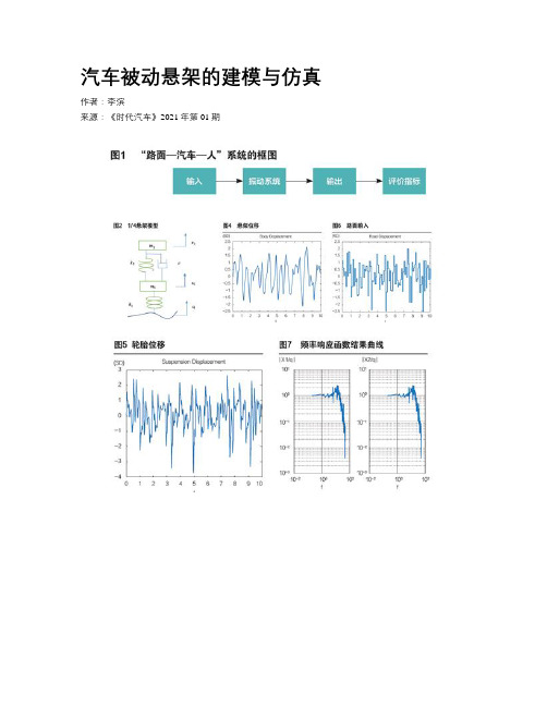
汽车被动悬架的建模与仿真作者:李滨来源:《时代汽车》2021年第01期摘要:汽车最早应用的是被动悬架,悬架是汽车行驶系的重要组成部分。
目前被动悬架应用广泛,通过计算机建模,并建立微分方程,利用现代控制理论的知识,建立二自由度悬架模型的仿真模拟图。
分析了悬架在随机输入情况下的悬架动行程、轮胎动位移。
仿真出频率函数响应结果曲线。
在计算机的模拟与仿真下,对被动悬架有了更深的了解,为进一步工程研究提供了基础。
关键词:被动悬架建模与仿真 MATLAB/Simulink 1/4悬架Modeling and Simulation of Automobile Passive SuspensionLi BinAbstract:Automobile manufacture first adopted the passive suspension. The suspension is important part of running system of vehicle. The passive suspension is widely used at present. Through computer modeling and establishing differential equation, the simulation diagram of 2-DOF suspension model is established by using the knowledge of modern control theory. The dynamic displacement of suspension and dynamic travel of tire with random input is analyzed in the article. The response curve of frequency function is simulated. Under the computer simulation, we have a deeper understanding of the passive suspension, which provides a foundation for further engineering research.Key words:passive suspension, modeling and simulation, MATLAB/Simulink, 1/4 automobile suspension1 引言懸架(suspension)的定义是汽车底盘的最重要组成部分,使汽车发动机通过离合器、变速箱、传动轴及汽车车桥的半轴和轮胎的连接将旋转运动变成汽车的直线运动。
汽车维修工程教育专业毕业论文三轴式手动变速器传动系统建模与运动仿真
本人郑重承诺:
我承诺所呈交的毕业设计(论文)是本人在指导教师的指导 下,按照学校和学院的有关规定,独立研究完成的。本人在毕业 设计(论文)写作过程中恪守学术道德和学术规范,设计(论文) 屮凡引用他人已经发表或未发表的成果、数据、观点等,均已注 明并列出了有关文献的名称、作者、年份、刊物名称和岀版文献 的岀版机构、出版地和版次等内容,除此Z外均为本人的观点和 研究成果。
如有违反,本人愿接受处罚并承担一-切责任。
承诺人签名(手写):
摘要1
••••••••••••••••••••••••••••••••••••••••••••••••••••••••••••••••••••••••••••••••••••••••••••••••••••••••••••••••••••••1
关键词:三轴式手动变速器:UGNX:参数化建模:运动仿真
The Modeling and Simulation of
Three-axis Manual Transmission System
Cai Li Tutor: Lu Guodong
(College of Engineering, Vocational and Technical Education >
该变速器的主要结构特点有:
(1)档和倒档为滑动齿套换档,二档装有锁销式惯性同步器,三、四、五、 六档装有锁环式惯性同步器。
(2)变速器外壳为整体式,变速器盖分成两部分,即上盖和顶盖。
(3)同步器可使换档方便,减少齿端冲击磨损,延长使用寿命。
(4)除一档和倒档外,其余档位速比CA15型汽车的速比大,六档为直接档。
Key Words:three-axis manual transmission; UG NX; parametric modeling; motion simulation
汽车发动机虚拟仿真实验教学平台开发与应用
现代电子技术Modern Electronics Technique2022年9月1日第45卷第17期Sep.2022Vol.45No.170引言“发动机构造”“发动机原理”和“发动机设计”是能源与动力(汽车发动机方向)专业的核心专业课程,为了加深学生对发动机结构、工作过程及工作原理的理解,同时也开设了“发动机速度特性实验”“发动机燃烧参数调整特性实验”和“发动机气门运动规律”等10项实验教学项目[1]。
实验教学项目在开展过程中遇到了教学资源紧张、学生操作安全隐患大、知识点覆盖不全面等问题,未能充分发挥实验教学的优势[2]。
本文针对以上问汽车发动机虚拟仿真实验教学平台开发与应用范鲁艳,曲大为,苏岩,杨硕(吉林大学汽车工程学院,吉林长春130025)摘要:汽车发动机实验课程是提高学生专业实践能力的重要环节,但在传统实验教学台架搭建过程中存在“耗时、耗能、耗力”的问题,并且受实验场地和成本的限制,学生开展实验的自由度和参与度较低,针对以上问题搭建了汽车发动机虚拟仿真实验教学平台。
平台以CA4DD 柴油机为建模对象,在对其结构分析的基础上利用CRUISE⁃M 软件完成了发动机进排气子系统、EGR 子系统等以及整机的模型搭建、参数输入与模型校核,以柴油机燃烧参数调整特性虚拟仿真实验为例,设计实验流程,展示了平台的实际应用。
学生可以根据搭建的CA4DD 一维性能仿真模型在课堂教学演示和自学之后,利用CRUISE⁃M 的在线和离线仿真方法,实现传统实验教学平台的升级,扩充现有的实验项目。
平台丰富了实验内容,弥补了当前发动机专业实践教学的缺陷,拓宽了学生的知识领域,提升了学生的学习兴趣和实践能力。
关键词:汽车发动机;实验教学平台;虚拟仿真;CRUISE⁃M ;进排气;EGR ;气缸;模型搭建中图分类号:TN02⁃34;G434文献标识码:A文章编号:1004⁃373X (2022)17⁃0163⁃06Development and application of automobile engine virtual simulation experimentalteaching platformFAN Luyan ,QU Dawei ,SU Yan ,YANG Shuo(College of Automotive Engineering ,Jilin University ,Changchun 130025,China )Abstract :Automobile engine experiment course is an important part to improve students ′professional practical ability.However ,the process of the traditional experimental teaching platform construction is time ⁃consuming ,energy ⁃consuming and effort ⁃consuming.In addition ,with the limitation of experimental site and cost ,students have low degree of freedom and participation in experiments.Therefore ,a virtual simulation experimental teaching platform for automobile engine is set up.Onthe platform ,the CA4DD diesel engine is taken as the modeling object.On the basis of the structural analysis of the CA4DD diesel engine ,the CRUISE ⁃M is used to complete the model building ,including engine intake &exhaust subsystem ,EGR subsystem and the model building ,parameter input and model checking of the whole engine.The virtual simulation experiment of diesel engine combustion parameter adjustment characteristics is taken as an example.The experiment procedures are designed to show the practical application of the platform.According to the built one⁃dimensional performance simulation modelof CA4DD ,students can realize the upgrade of the traditional experimental teaching platform and expand the existing experimental projects by CRUISE⁃M online and offline simulation methods after classroom teaching demonstration and self⁃study.The platform can enrich the experiment content ,make up for the defects of the current practical teaching of engine major ,broaden the knowledge field of students and improve their learning interests and practical abilities.Keywords :automobile engine ;experimental teaching platform ;virtual simulation ;CRUISE ⁃M ;intake and exhaust ;EGR ;cylinder ;model buildingDOI :10.16652/j.issn.1004⁃373x.2022.17.030引用格式:范鲁艳,曲大为,苏岩,等.汽车发动机虚拟仿真实验教学平台开发与应用[J].现代电子技术,2022,45(17):163⁃168.收稿日期:2022⁃01⁃21修回日期:2022⁃02⁃18基金项目:国家自然科学基金面上项目(51876079);吉林大学教学改革项目(2019XYB156)163现代电子技术2022年第45卷题,利用动力系统一维仿真软件CRUISE⁃M,搭建了典型汽油机和柴油机的整机模型,分析了发动机结构参数、控制参数和环境参数对发动机燃烧过程、动力性、经济性和排放的影响规律,完成了虚拟仿真实验教学平台的开发,扩充了实验教学所涵盖的知识点范围,提高了学生学习的主动性和参与度,增强了学生对相关知识点的理解。
基于CarSim的FSC赛车建模与操纵稳定性仿真研究

基于CarSim的FSC赛车建模与操纵稳定性仿真研究贾丽娟,李刚,韩忠浩(辽宁工业大学汽车与交通工程学院,锦州 121001)摘要:针对FSC赛车开发过程中的操纵稳定性分析,论文基于车辆系统动力学仿真软件CarSim进行建模与仿真研究。
应用CarSim建立了包含车体、轮胎、转向系统、悬架系统、制动系统及传动系统的FSC赛车整车动力学模型,并应用3D软件绘制三维车身、尾翼和发动机模型导入到CarSim中实现整车动画仿真。
在CarSim中按照比赛要求设置方向盘角阶跃输入转向瞬态响应试验工况和蛇形试验工况进行FSC赛车操纵稳定性仿真分析。
仿真结果表明:开发的FSC赛车具有良好的操纵稳定性。
关键词:FSC赛车;CarSim;操纵稳定性;建模;仿真Study On Modeling and Simulation of Handling and Stabilityfor FSC Racing Car Based on CarSimJia Li-juan,Li Gang,Han Zhong-hao(College of Automobile and Traffic Engineering, Liaoning University of Technology,JinzhouLiaoning 121001, China)Abstract: For the analysis of handling and stability,modeling and simulation of FSC racing car based on dynamics simulation software CarSim were studied.The car body model,tire model,steering system model, suspension system model, brake system model and driveline model were built in the CarSim.The three-dimensional body, tail and engine models were built by 3D software and import to CarSim for animated simulation.The steering step input transient response test and snake test were set in the CarSim according to the raceing requirements.The simulation results showed that the FSC racing developing had good handling and stability.Key words: FSC racing car; CarSim; handling stability; modeling; simulation1 前言中国大学生方程式汽车大赛(简称“中国FSC”)是由中国汽车工程学会发起的、全国具有汽车工程专业高校学生参与的国家级大学生汽车专业赛事[1]。
纯电动汽车动力性匹配设计与模型仿真

Modeling and Simulation 建模与仿真, 2020, 9(3), 357-366Published Online August 2020 in Hans. /journal/moshttps:///10.12677/mos.2020.93036Dynamic Matching Design and ModelSimulation of Pure Electric VehicleWentao Zhang, Li Ye, Zhijun Zhang, Huan Ye, Mengya ZhangSchool of Power Engineering, University of Shanghai for Science and Technology, ShanghaiReceived: Aug. 6th, 2020; accepted: Aug. 20th, 2020; published: Aug. 27th, 2020AbstractBased on the selection of basic vehicle parameters and the determination of performance indica-tors, this paper carries out the design matching of dynamic performance parameters of pure elec-tric vehicles. Then, a pure electric vehicle dynamic simulation model is established by vehicle si-mulation software, and the vehicle dynamic performance index is simulated and analyzed by in-putting relevant parameters. Finally, the rationality of simulation model and parameter matching is verified by real car test. This study can provide theoretical basis for the matching design of var-ious systems in the initial stage of pure electric vehicles, carry out range and performance test evaluation of vehicle performance, and provide reference for the analysis of dynamic performance and economic index of pure electric vehicles.KeywordsPure Electric Vehicle, Parameter Design Matching, Vehicle Power Model, Simulation Analysis纯电动汽车动力性匹配设计与模型仿真张文韬,叶立,张志军,叶欢,张梦伢上海理工大学动力工程学院,上海收稿日期:2020年8月6日;录用日期:2020年8月20日;发布日期:2020年8月27日摘要本文基于对整车基本参数的选取与性能指标的确定,进行了纯电动汽车动力性能参数的设计匹配。
汽车稳定性控制系统模型及横摆控制仿真_欧健
。 本文简化了车辆模型, 结
合汽车动力学稳定性控制要求, 建立了可实时计 算的整车动力学仿真模型, 通过对鱼钩试验的仿 真分析, 验证了 ESC 系统直接横摆控制( direct yaw control, DYC ) 对汽车横摆运 动、 侧倾运动的控制 效果。
1
1. 1
车辆动力学模型建立
八自由度整车模型 建立包括纵向运动、 侧向运动、 横摆运动、 侧
[4 ]
稳定性控制。 本文以横摆角速度为控制变量, 基 于模糊控制理论
[6 - 7 ]
, 以汽车实际横摆角速度与
名义横摆角速度的误差 E 以及误差变化率 EC 为 输入, 修正横摆力矩 M 为输出, 设计横摆角速度反 馈模糊控制器
[8 - 10 ]
。 模糊逻辑规则如表 1 所示,
PS、 Z、 NS、 NB 为模糊语言变量, 其中 PB 、 分别表示 正小、 零、 负小、 负大。 正大、
和车辆参考模型。采用车辆横摆角速度的状态差异法 , 基于模糊控制理论制定了直接横摆控制 实现了 ESC 系统对车辆的稳定性控制。对典型工况鱼钩试验进行仿真分析。 结 果表明: 策略, 所制定的控制策略可以有效地实现横摆稳定性控制, 而且减小 了侧 向加 速度, 使汽 车 具有一 定 的抗侧翻能力, 提高了汽车的稳定性和安全性。 关 键 词: 电子稳定控制; 模糊控制; 直接横摆; 侧倾 文献标识码: A 文章编号: 1674 - 8425 ( 2013 ) 02 - 0001 - 05 中图分类号: U416. 6
2 重庆理工大学学报 馈的控制方法对前外轮制动, 增强了 ESC 系统的 侧翻控制功能。博世公司在 ESC 系统的基础上描 述了侧翻缓解功能
[3 ]
② 各轮胎机械特性相同; ③ 悬架弹簧和阻尼均为 线性, 且二者平行; ④ 直接以前轮转角为输入, 且 两前轮转角相等; ⑤ 忽略空气阻力和滚动阻力的 影响。八自由度整车模型如图 1 所示。 1 ) 纵向运动方程: m( v x - v y γ) = ( F xfl + F xfr ) cosδ - ( F yfl + F yfr ) sinδ + F xrl + F xrr 2 ) 侧向运动方程: m( v y - v x γ) = ( F xfl + F xfr ) sinδ + ( F yfl + F yfr ) cosδ + F yrl + F yrr 3 ) 横摆运动方程: ( 2) ( 1)
汽车线控转向系统的结构分析
前言
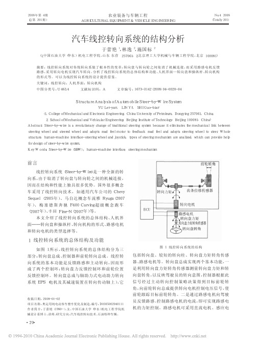
线控转向系统( Steer- by- Wire) 是一种全新的转 向系, 由于取消了转向盘与转向轮之间的机械连接, 因而在结构和性能上独具很多优势。国外很多概念 车采用了线控转向技术, 如通用汽车公司的 Chevy Sequel ( 2005 年) 、马自达概念车流雅 Ryuga( 2007 年 ) 、 梅 塞 德 斯 奔 驰 F400 Carving 超 级 概 念 跑 车 ( 2007 年) 、丰田 Fine- N( 2007 年) 等。
日本精工试制出了双连杆臂式线控转向系统, 利用两个转向电机的旋转力矩直接驱动前轮转向拉
图 7 线控独立转向机构
杆, 并在第 40 届东京 车 展 ( 2007 年 10 月 27 日~11 月 11 日) 上进行了展出。多传感轮毂可检测来自路 面的三个方向负荷, 即使路面状况发生变化, 也可将 轮胎舵角控制到最佳状态, 从而使车辆驶向驾驶员 希望的方向。原来的线控转向系统大多沿用普通齿 条驱动型 EPS( 电动助力方向) 的驱动机构等。而此 双连杆臂式线控转向系统利用相对于马达旋转轴呈 直角伸出的转向臂分别操纵, 可省掉左右轮齿条和 小齿轮, 因此大幅简化机构、提高空间效率。
2. School of Mechanical and Vehicular Engineering, Beijing Institute of Technology, Beijing 100081, China) Abstr act: Steer- by- wire is a revolutionary change of traditional steering system because it eliminates the mechanical link between steering wheel and steered wheel and adopts road feel motor to feedback road feel and adopts steering wheel to steer. Whole structure, human- machine interface- steering wheel and joystick, types of steering mechanism are analized, which can provide help for design of steer- by- wire system. Key Wor ds: Steer- by- Wire ( SBW) ; human- machine interface; steering mechanism
六旋翼植保无人机模糊自适应PID控制

六旋翼植保无人机模糊自适应PID控制李永伟;王红飞【摘要】六旋翼植保无人机在作业过程中自身载荷变化将引起飞行控制性能下降、抗扰动能力降低等问题.为了提高六旋翼植保无人机的可控性,通过对六旋翼植保无人机在喷洒农药过程中进行分析和建模,推导出植保无人机时变动力学模型,提出了一种模糊自适应PID控制算法,模糊自适应PID算法适应性强,参数整定简单,提高了系统动态响应和稳态性能.将各个传感器的测量参数输入到模糊自适应PID算法中,可以得到对应的控制量,实现飞行器稳定运行.通过使用Matlab软件对飞行系统进行仿真,并结合实验平台实际飞行控制表明,系统的动态性能和稳定性得到了有效提高.【期刊名称】《河北科技大学学报》【年(卷),期】2017(038)001【总页数】7页(P59-65)【关键词】自动控制理论;模糊PID;植保无人机;飞行控制;飞行器建模【作者】李永伟;王红飞【作者单位】河北科技大学电气工程学院,河北石家庄 050018;河北科技大学电气工程学院,河北石家庄 050018【正文语种】中文【中图分类】TP273;V249.121李永伟, 王红飞.六旋翼植保无人机模糊自适应PID控制[J].河北科技大学学报,2017,38(1):59-65. LI Yongwei, WANG Hongfei.Fuzzy adaptive PID control for six rotor eppo UAV [J].Journal of Hebei University of Science and Technology,2017,38(1):59-65.六旋翼植保无人机是一种典型的多变量欠驱动时变系统,且系统具有强耦合性的特点[1-3]。
植保无人机与其他无人飞行器有很多不同点,植保无人机的主要特点是靠近地面低空飞行,并且无人机在喷散农药作业时,很容易受到地面地势的变化、局部气流的变化、电池电量变化和自身质量变化的影响。
基于AMESim的汽车液压ABS建模与仿真

收稿日期:2011-03-10基金项目:汽车安全与节能国家重点实验室开放基金(11151);汽车动态模拟国家重点实验室开放基金(20091113)作者简介:徐国民(1984-),男,江苏宿迁人,硕士研究生,主要从事汽车电子及控制技术的研究.文章编号:1006-3269(2011)01-0037-06基于AM ESim 的汽车液压ABS 建模与仿真徐国民1,马明星1,2,黄锦川2,管延才1(1.扬州大学机械工程学院,江苏扬州225127; 2.汽车安全与节能国家重点实验室,北京100084)摘 要: 利用ABS 混合仿真试验台实测制动压力,对某型号A BS 进行阶梯增减压制动的实验测试.在分析ABS 液压系统的组成和工作原理的基础上,基于A M ESim 建立了包括液压调节器、制动主缸、电磁阀及制动轮缸等模型.仿真了阶梯增减压制动.正常制动、常加常减制动的仿真结果与实验结果基本一致.结果表明:所建液压A BS 系统模型和参数的设置是比较准确的.该研究为A BS 轮缸压力的精细调节和精确理论建模提供了重要的实验和理论依据.关 键 词: A BS;液压系统;A M ESim;仿真实验中图分类号: U 463.5 文献标识码: A do i:10.3969/j.issn.1006-3269.2011.01.009防抱死制动系统(Anti 1o ck Braking Sy stem,以下简称ABS)是汽车主动安全技术的重要领域.国外虽然已经有成熟产品,但由于国外技术的保密,其压力控制模型和具体技术参数很难获取,而国内ABS 技术并不成熟,主要依赖于进口.中国目前对ABS 制动系统的研究,大多集中在ECU(Electronic Co ntro l Unit)的控制理论及ABS 的匹配试验方面,而对ABS 液压系统的理论模型研究相对较少,因此,在理论模型包含的多个液压单元的诸多重要参数的选择和匹配问题上缺乏系统的理论研究[1].本文以AM ESim 软件为平台,建立了完整的ABS 液压系统模型,设置相关参数并仿真了阶梯增压、减压制动.其仿真结果与实验结果基本一致.本文还通过实验验证了所建模型的正确性,并在此基础上仿真了正常制动和常加常减制动.其结果为以后的ABS 轮缸压力的精细调节和精确理论建模提供了重要的实验和理论依据.1 ABS 液压系统数学模型1.1 ABS 液压系统的组成图l 为典型的ABS 液压系统结构组成.在制动时,制动踏板力经真空助力器的放大后作用在总泵上;总泵的2条输出管路分别将压力作用在交叉的2个车轮上.1.2 ABS 液压系统的工作原理ABS 液压系统的工作原理是利用电磁阀的开关动作实现轮缸内的增压、保压和减压3种状态.ABS 未动作时,增压阀常开,减压阀常闭;在紧急制动情况下,驾驶员踩下制动踏板,压力很快上升,当车轮有抱死趋势时,关闭增压阀,进行保压,如果车轮仍有抱死趋势,则打开减压阀,进行减压.在图1所示的减压过程中,制动液的流动通道为:左前轮轮缸 回油电磁阀 ABS 低压储液器 回油单向阀 ABS 回油泵 回油单向阀 制动总泵 储液室[2].随着制动轮缸中的制动液流回储液室,轮缸中的压力降低,使车轮转速充分恢复,然后再重新进入升压阶段.在升压过程中,为了保持制动过程的平顺性而防止出现振荡,一般采用阶梯升压策略[3].这种压力调节方式的特点在于:压力的变化是非连续的,但通过3种压力状态的高速切换,可实现精细的压力调节,并且具有简单、可靠和便于电气控制的优点.因此,这种压力调节方式得到了广泛应用.1.总泵2.液压调节系统3.增压阀4.减压阀 5、8.蓄能器 6.ABS电机 7.ABS回油泵 9.进油电磁阀 10.出油电磁阀图1 ABS液压系统结构组成示意图1.3 主要液压元件的数学模型根据流体力学的相关理论可以建立描述系统主要液压元件动态性能的数学模型,为汽车ABS液压系统动态性能仿真分析和液压单元设计提供理论依据[4].1.3.1 ABS电磁阀模型加压阀主要由动铁和阀芯、静铁、回位弹簧、隔磁管、阀座等零件组成,如图2所示.图2 A BS加压型阀模高速开关电磁阀包括增压阀和减压阀.其中,增压阀是常开阀,减压阀是常闭阀.ABS液压系统的高频响应性能很大程度上取决于ABS电磁阀的动态响应特性,动铁和阀芯可以视为有限位运动的质量块,受电磁力、弹簧力、液压力、冲击力和粘滞力等作用.电磁阀的线圈通电后产生电磁力,用来控制电磁阀的开关状态.动铁和阀芯的动力学方程为:d vd t=1m[F m(i,x)-k(x0+x)+F p(x)-F f-cv2]d xd t=v(1)式中:m 动铁和阀芯的质量和;x 动铁和阀芯的位移;v 动铁和阀芯的速度;x0 回位弹簧预压缩量;i 线圈电流;k 回位弹簧刚度;c 速度阻尼系数;F p 阀芯组件液压力;F m 电磁力;F f 摩擦力.电磁阀线圈电流i的微分方程为:d id t=[U-iR-ivL(x,i)x]/[L(x,i)+i L (x ,i) i](2)式中:U 线圈电压;R 线圈电阻;L 线圈电感.阀起到节流作用,根据其流量特性,压力变化率一般表述为:d p cd t =k 1 pk 2(3)式中:k 1k 2 常系数;p 阀口两侧压差;p c 管路的当前压力.电磁阀可视为一阶延迟环节,电磁阀响应比较快,在ABS 工作过程中可以认为是阶跃响应.一阶系统单位阶跃响应的时域表达式为:c(t)=1-e -t/T(4)其中,T 为时间常数,其值的大小反应了液压系统的增压、减压能力.1.3.2 制动轮缸模型制动轮缸是一个作用有弹簧力、液压力和阻尼力的液压缸.制动钳的微分方程为:m d 2x d t2=ps -k sin (x -x g )-f d[sin (x -x g )]d t -F s -f ric -f visc (5)sin (x -x g )=x -x g ,(x -x g >0)0,(x -x g <0)式中:p 制动轮缸液压压力;m 制动钳可动部分质量;x 制动钳位移;F s 制动钳回位弹簧压力;s 油液作用等效面积;f ric 制动钳移动中的摩擦力;f visc 粘滞力;x g 摩擦块与制动盘之间间隙;k 制动盘抗压刚度;f 制动盘阻尼系数.1.3.3 液压管路模型连接ABS 液压调节器和制动系统其他部件的管路分为硬管和软管,如图1所示.测量软硬管的直径、长度、管壁厚度,管路材料的杨氏模量由AMESim H elp 文件获取.软管流速的计算与硬管基本相同,但由于管路材料不同,体积模量差异很大.软管压力特性的计算如下: P t =- A qx式中: 管路和流体的有效体积模量.=11 fluid +1 hose式中: fluid 流体体积模量;hose 管路体积模量.硬管中压力流量特性的计算如下: P t =-B A Q x式中:B 管路和流体的有效体积模量;A 管路截面积.流速计算为:v =2D | P -9.81 L sin ( )|L f f(6)式中:v 流速;D 管路直径;P 计算步长终点和起点之间的压降;油液密度;L 管路长度; 管路弯角;f f 摩擦系数.2 基于AM Esim 的液压A BS 建模与仿真AM ESim 作为多学科领域复杂系统高级建模和仿真的主流平台,主要应用于液压/机械系统的建模、仿真及动力学分析.它用直观的图标符号代表系统的各个元件,包括车辆所涉及的各个学科领域的基础库:机械、液压、气动及电磁等元件.AM ES im 仿真在汽车燃油喷射系统、润滑回路、车辆悬挂系统、制动系统、传动系统、动力系统、冷却系统、废气回流、热管理和热分配控制等方面都有很好的应用[5].AM ESim 系统模型搭建步骤如下: 依据ABS 的工作原理,在草绘模式下从AMESim 元件库中选取合适的模块,并按照图3搭建; 定义整个系统的液压参数,如制动液的体积模量、动力粘度和温度等,以及各个元器件的内部结构参数等; 设定仿真参数、运行仿真并查看结果.1.制动主缸2.单向阀3.增压阀4.减压阀5.蓄能器6.泵7.电机8.制动轮缸9.制动液图3 液压A BS系统的A M Esim模型根据系统组成和控制原理建立液压ABS模型,主要包括制动主缸、增压阀模型、减压阀模型、泵模型、单向阀模型、低压蓄能器模型和缓冲腔模型,它们也都来自液压元件库;控制信号采用控制信号库中的模型;电动机模型来自机械元件库;制动轮缸采用AMESim制动系统给出的车辆轮缸模型[6].建立四轮车辆模型时,为了与实验相匹配,仿真时取左前轮进行仿真.2.1 基于AM ESim的ABS性能仿真分析与参数设置利用AM ESim软件在液压建模和动态仿真方面的优势,对ABS液压调节器的工作过程,实现增压、保压及减压工作过程进行仿真分析,探讨相关参数对ABS液压响应特性的影响.设定主缸压力为6MPa,根据上述理论设定模型参数,给定A BS电磁阀脉冲控制信号,周期为0.5s,脉宽为6ms.通过加、减压阀的配合,使制动压力升至最高后,先阶梯形下降11个周期,保持2s,再阶梯形上升11个周期.仿真时间共20s,步长0.0001s.试验与仿真采用相同脉冲控制信号,试验数据采集时间也为20s.得到的仿真与试验结果如图4所示.阶梯加、减压实验是为了研究实际工况中猛踩刹车下ABS和制动系统的特性.由图4可以看出:开始主缸压力为6M Pa,并保持了1.74s;随着11个阶梯形减压而下降到最小压力为1.58M Pa,需要图4 阶梯加、减压仿真与实验的对比结果5.01s,并保持2s;之后再阶梯形上升11个周期,增到最大压力5.98M Pa.同样设定正常制动和常加常减压主缸压力为6MPa,根据上述理论设定模型参数,给定ABS 电磁阀脉冲控制信号(正常制动程序中对ABS 输入的信号都为0值),周期为0.5s,脉宽为6ms,设定正常制动模型和常加常减制动模型信号,其仿真结果如图5、图6所示.正常制动实验是为了检测制动系统本身的特性,即制动加压能达到的最高压力和减压能达到的最小压力.模拟驾驶员遇到障碍踩下踏板时的主缸压力变化为6M Pa 并保持6s,然后稍松踏板使主缸压力达到最低压力约为0.68MPa,并保持3.5s,之后驾驶员再次踩下踏板使主缸压力达到最高压力约为5.8M Pa,并一直保持到最后总时间20s.此过程中,ABS 一直未工作.常加常减压是在ABS 作用下制动能达到的最大和最小压力.可以验证在ABS 作用下制动压力能不能达到正常制动的水平.同样是模拟驾驶员在踩踏踏板过程中,在ABS 的作用下主缸压力的变化.由图6可以看出,主缸能达到的最大压力为5.63MPa,最低达到0.31M Pa.2.2 仿真结果与实验影响因素的分析从以上仿真和实验结果对比可以看出,所建ABS 液压系统模型以及参数的设置是比较准确的,但也存在误差(见表1).表1 不同工况实验与仿真结果误差统计工况ABS 工作状况实验与仿真结果误差统计结果/%阶梯加减压工作10正常制动未工作3常加常减制动工作6表1反映了上述3种不同工况在主缸为6M Pa 时,实验与仿真结果存在的误差.分认为析误差存在是由几个方面引起的.(1)ABS 控制系统的控制存在滞后环节.主缸压力与轮缸压力的变化要经过加压阀和减压阀,而加压阀和减压阀打开和关闭的时间则影响轮缸压力的变化.两阀打开和关闭的时间越长,则系统的滞后性就越大,引起实验和仿真的误差也就越大.(2)本系统是采用脉冲信号控制的,一次脉冲压力的误差非常小,但多次累计以后,仿真结果会与试验结果有明显的差异.阶梯制动图6越到后期,误差也就越大.(3)电磁阀节流口径大小不一致和形状不一样.单向阀泄漏,电磁阀阀杆行程不一致性,电磁阀节流指数的设计,制动管路长度以及沿程压力损失,管路的传输延迟,压力波传播速度等,都会使仿真和实验结果产生误差.这主要是因为理论模型基本上忽略了这些实际存在的东西.3 结束语通过AM ESim建立完整的ABS液压制动系统仿真模型.经试验验证,该模型正确可靠,并且选择的各部模型参数比较准确.在此基础上,设定了正常制动模型和常加常减制动模型信号,得到了相同仿真时间和步长的结果.为研究者提供了非常全面的研究对象数据,为改进ABS的性能提供了简便有效的手段,为控制逻辑参数的选择提供了有力的依据.该模型与控制逻辑模型及整车动力学模型结合可进行整车路面防抱死制动研究,为ABS轮缸压力的精细调节和精确理论建模提供了重要的实验和理论依据.因此,该模型为更全面的研究奠定了基础.但理论与实验也存在一定的误差,需要进一步研究各种因素对制动系统的具体影响.参考文献:[1] 祁雪乐.ABS液压制动系统动态特性研究和综合仿真匹配平台的建立[D].北京:清华大学汽车工程系,2005.[2] 谢敏松,李以农.汽车ABS液压调节器建模与分析[J].汽车技术,2007,38(4):16-18.[3] 陶润,张红,付德春,等.ABS液压系统仿真与电磁阀优化[J].农业工程学报,2010,26(3):135-139.[4] 李东敬王磊.汽车ABS液压调节器建模与仿真分析[J].机床与液压,2009,37(11):219-221.[5] 付永领,祁晓野.AM ESim系统建模和仿真-从入门到精通[M].北京:北京航空航天大学出版社,2006.[6] 王吉,李建华,靳力强,等.基于AM Es im与Sim ulink/S tateflow的汽车ABS联合仿真建模与仿真研究[J].汽车技术, 2010,41(1):25-33.Modeling and S imulation of Automobile Hydrau lic ABS Based on AMES imXU Guo min1,M A Ming xing1,2,H U ANG Jin chuan2,GU AN Yan cai1(1.Scho ol of M echanical Eng ineering,Y ang zho u U niv ersity,Y ang zho u225127;2.Department of A utomo tive Engineer ing,T singhua U niversit y,Beijing100084,China)Abstract:Based o n A BS hy dr aulic test bench,ex per i menta l test on the step brake was do ne for a ty pe of A BS.A M ESim model including hy dr aulic reg ulator,main cy lin der,step br ake soleno id valve and w heel cy linders is set up based on the analysis of A BS hy dr aulic system composition and w or king principle.T he simulat ion result of step br ake, the normal br ake,and on-off brake is consist ent w ith the test results.T he result sho ws:hydr aulic ABS sy stem mo del and parameter s selection a re close to t he truth.T he results pro vide an impo rtant experimental basis fo r ABS w heel cy l inder pressure o f fine-tuning and precise theo retical model.Key words:A BS;hydraulic sy st em;AM ESim;simula tio n o f experiment。
新工科和虚拟实验下汽车设计课程教学改革
10.16638/ki.1671-7988.2021.010.047新工科和虚拟实验下汽车设计课程教学改革*安晓东,李亚丽,候军兴,张华阳(郑州航空工业管理学院航空工程学院,河南郑州450046)摘要:新工科对汽车设计课程建设的要求与实际教学过程中存在滞后和不符合现象,论文对汽车设计教学和考核模式进行相关改革;针对不同汽车系统的应用背景、功能分类、选择方案和工作原理等理论部分,进行了实验室教学与其他教学模式融合的方法;针对汽车系统结构的设计分析和计算,进行了三维建模和虚拟仿真试验等方法;根据教学内容和方式的不同,采用综合考核方式。
改革教学效果评价显示,培养了学生解决实际问题的能力和学习兴趣,融合了学生获得的设计技能与社会实际需求相符合的目标。
关键词:汽车设计;虚拟仿真;产学研创;新工科中图分类号:G642 文献标识码:A 文章编号:1671-7988(2021)10-152-03The Teaching Reform of Automobile Design Course Based on the NewEngineering and Virtual Simulation Test*An Xiaodong, Li Yali, Hou Junxing, Zhang Huayang( Zhengzhou University of Aeronautics, School of Aeronautical Engineering, Henan Zhengzhou 450046 )Abstract:There is a lag and the inconsistency between the requirements of the new engineering course and the actual teaching process. In this paper, it is reformed for the mode of the teaching and the patterns of the course examination about the automobile design. The method of the laboratory teaching and the other modes of the teaching are carried out, according to the background of the application, the classification of the function, the selection of the scheme and the working principle of the different automobile systems. The three-dimensional modeling and the virtual simulation test are carried to the analysis and calculation of the automobile system or the structure. The comprehensive assessment methods are adopted, according to the different contents and the methods of the teaching. The analysis for the effects of the teaching reform shows that it has cultivated the students' ability to solve the problems of the practical and the interest of the learning, and has integrated the design skills of the students with the actual needs of the society.Keywords: Automotive design; Virtual simulation; Industry university research and innovation; New engineering CLC NO.: G642 Document Code: A Article ID: 1671-7988(2021)10-152-03前言汽车设计课程是车辆工程专业核心课程之一,包括汽车总体布局设计、汽车零部件设计和汽车外观设计等三方面内容,传统汽车设计课程主要讲授前两部分内容[1]。
轮胎动态模型研究的进展
轮胎动态模型研究的进展危银涛;冯希金;冯启章;刘源;何园【摘要】轮胎是汽车唯一接地部件,它提供汽车运动需要的所有驱动、转向和制动力。
轮胎力学是汽车动力学的基础。
汽车动力学及其控制技术的进一步发展有赖于精确的轮胎动态模型技术。
该文综述了轮胎动态模型发展历史与现状,这包括:汽车操稳仿真模型、汽车舒适性仿真模型和汽车疲劳载荷仿真模型。
从建模方法的角度,即基于物理的、基于实验的和基于结构的三类方法,对轮胎动态模型的优缺点进行了梳理。
可以预计:轮胎动态模型的未来发展将以基于结构的先进轮胎模型为主,与汽车动力学仿真、汽车主动安全系统开发深度融合,并最终走向汽车—轮胎—道路相互作用定量化理论。
%Tire is the only link between tire and road, which provides al force and moments for vehicle motion including driving, steering and braking. Tire mechanics is the base for vehicle dynamics, which progress depends on to a large extent the precise tire dynamical model. This paper reviews the state of the art for tire dynamical models, including handing tire model, ride comfort model, and durability load simulation model. The advantages and disadvantages for three tire modeling approaches, i.e. simple physics based, empirical based and structure based, are compared. It can be concluded that the fufure of the tire model lies in the so caled advanced tire model, i.e. structure based model wil gain more advances and interest in both academics and industries, the tire dynamical model wil be integrated with vehicle dynamics simulation and vehicle active safety system development. The vehicle-tire-road indication theory wil be ultimate goal of the research.【期刊名称】《汽车安全与节能学报》【年(卷),期】2014(000)004【总页数】13页(P311-323)【关键词】轮胎动态模型;汽车动力学仿真;疲劳载荷分析;先进轮胎模型;汽车-轮胎-道路相互作用【作者】危银涛;冯希金;冯启章;刘源;何园【作者单位】清华大学汽车安全与节能国家重点实验室,北京 100084,中国;清华大学汽车安全与节能国家重点实验室,北京 100084,中国;清华大学汽车安全与节能国家重点实验室,北京 100084,中国;清华大学汽车安全与节能国家重点实验室,北京 100084,中国;清华大学汽车安全与节能国家重点实验室,北京100084,中国【正文语种】中文【中图分类】U461;TB942轮胎是唯一连接汽车和道路的部件。
钛合金表面的电火花着色加工技术
钛合金表面的电火花着色加工技术高上品(上海第八机床厂,上海200030)摘要:介绍了利用电火花加工技术对钛合金表面着色的原理、加工过程、工艺特性、表面质量和应用实例,指出了该技术的实用价值和应用前景。
关键词:钛合金;电火花加工;表面着色;氧化膜钛是一种重量轻、强度高、耐蚀性强的金属材料,用途很广。
在航天航空和机械制造等工业部门甚至在生活日用品中均有应用。
钛表面呈银白色,类似于不锈钢和铝的表面。
由于产品表面的颜色往往影响到产品本身的价值,因此,对产品表面色彩的要求日益受到重视,在这种需求的背景之下,研究开发了钛合金表面的电火花着色加工技术,这也是电加工领域中出现的一项新的加工技术。
钛合金表面的着色加工通常是采用电解阳极氧化法,但这种方法的工艺过程较为复杂,成本也较高。
相比之下,电火花表面着色的加工方法则工艺过程简单,并可获得不同颜色的加工表面,是一种值得推广使用的着色加工方法。
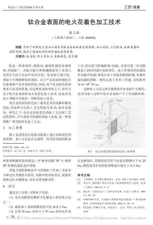
1加工原理图1是采用电火花线切割加工进行表面着色的原理图。
加工方法是在完成第一次形状切割的粗加收稿日期:2004-08-30作者简介:高上品,男,1936年生,高级工程师。
工后,给以适当的偏移量(切深),在进行第二次切割精加工的同时进行表面着色。
加工所使用的电源是单向脉冲电源,将钛合金工件接电源的阳极,电极丝接电源的阴极。
使用去离子水作工作液,其电阻率为4@1048#cm。
这种加工方法之所以能使钛合金表面产生颜色,是因为加工过程中钛合金表面产生了氧化膜所致。
图1电火花线切割表面着色加工原理图和表面粗糙度值的稳定;À/脉冲间隔0和/X轴停顿0参数的选取也应重视。
其他方面的影响也不可忽视如工件加工余量多少和定位夹紧的可靠性、电极丝的形状误差、张紧程度和定位夹紧情况,还有皮带的脉动等。
6结论通过以上分析,可得如下结论:(1)电火花磨削是精密小孔精加工的有效方法之一。
(2)最低加工表面粗糙度值可达R a0.2L m。
(3)长度30mm、内径小于<1mm的内孔经电火花磨削后,其圆度误差用气动量仪检测小于0.25 L m,圆柱度误差的实验参数最小值小于0.5L m。
- 1、下载文档前请自行甄别文档内容的完整性,平台不提供额外的编辑、内容补充、找答案等附加服务。
- 2、"仅部分预览"的文档,不可在线预览部分如存在完整性等问题,可反馈申请退款(可完整预览的文档不适用该条件!)。
- 3、如文档侵犯您的权益,请联系客服反馈,我们会尽快为您处理(人工客服工作时间:9:00-18:30)。
Modeling and Simulation of Automobile Braking System Based on Kinetic Energy ConversionWenjuan Li, Xudong Wang, Xue Leng, and Meng WangCollege of Electrical & Electronic Engineering, Harbin University of Science & Technology, Harbin, China.Email: lwenjuan@Abstract—Fatal traffic accidents are related with the overlength braking distance and sideslip when the automobile is braked in an emergency. It is very important to study and improve the braking ability of the automobile. The anti-lock braking system (ABS) is the active method of increasing the braking ability. The ABS controller is the key to ABS. The modeling and simulation of the automobile braking system can be used in designing the ABS controller. The general braking model is built by analyzing the forces on the automobile body and it is difficult to be understood.A new method which establishes the braking model is presented in this paper. When the automobile is braking, the kinetic is worn down by frictions that come from the wheels and road, the wheels and the braking block. A single wheel mathematical model is deduced with this principle. The simulation models of this braking system and ABS are established. Simulations under Matlab/ Simulink are made. The braking distances obtained by the simulation are compared with the known data. The results show that the braking model based on the kinetic energy conversion is reliable. This method can provide a new way to analyze the automobile braking process.Keywords—Braking model; Kinetic energy; Anti-lock braking systemI.I NTRODUCTIONThe automobile is one of the most important vehicles. The security and comfort are the focuses concerned by the people. The braking ability is the main index representing the security of the automobile which is running on the road. Fatal traffic accidents are related with the overlength braking distance and sideslip when the automobile is braked in an emergency, as in [1]. With the increase of the quantity and running speed of the automobile the damages brought to people by the traffic accidents are more serious. It is very important to study and improve the braking ability of the automobile. Ref. [2] pointed out that the anti-lock braking system (ABS) is the active method of increasing the braking ability. The ABS controller is the key to ABS. The modeling and simulation of the automobile braking system can be used in designing the ABS controller.The general braking model is built by analyzing the forces on the automobile body and is difficult to be understood, as in [3] and [4]. A new method which establishes the braking model is introduced in this paper. The kinetic is worn down by frictions that come from s and road, the wheel and braking block when the automobile is braking. A single wheel mathematical model is deduced with this principle. In order to validate this model, simulations with ABS and no ABS model are done in the Matlab/Simulink environment.II.E STABLISHMENT OF M ATHEMATICAL M ODEL OFB RAKING S YSTEMThe braking model depends on the decrease of kinetic energy when the automobile is braking. It consists of the kinetic energy dissipating model, speed model, fluid braking model and slip rate versus adhesion coefficient model.A.Kinetic Energy Dissipating ModelThe kinetic energy of the automobile body is mostly dissipated by the frictions between the wheel and the ground, the brake sheet and brake disc in the braking process.The initial kinetic energykE of the automobile body is22mvE k=, (1) where m is the mass of the automobile in kilograms (kg) and v0 is the initial speed (m/s).From 0 to t, the energy 1Q dissipated by the friction between the wheel and the ground is given bymgdtRvQtv01)(μω∫−= , (2) where t is the braking time in seconds(s); v v is the automobile body speed in the braking process (m/s); ω is the angular velocity of the wheel (rad/s); μ0 is the friction coefficient between the wheel and the ground;R is the radius of the brake disc (m).From 0 to t, the energy 2Q dissipated by the brake can be expressed in mathematically,RdtpSQtmωμ∫=2, (3) where p is the pressure within the wheel cylinder (MPa); S is the area of wheel cylinder (m2); μm is the friction coefficient between the brake sheet and brake disc. According to the law of conservation of energy the following equation is obtained,2/221vk mvQQE=−−, (4) that is978-1-4244-1849-7/08/$25.00○C2008 IEEESlip Rate2)(2200020v tm t v mv rdt pS mgdt R v mv =−−−∫∫ωμμω . (5)Equation (5) is the kinetic energy dissipating model of the automobile.B. Slip Rate Versus Adhesion Coefficient ModelThe braking process of the automobile is influenced by the adhesive force between the ground and the wheel. This force is associated with the adhesion coefficient. The adhesion coefficient is the ratio of the adhesive force to the vertical load which acts on the wheel. The adhesion coefficient is mostly determined by roads, tires and the slip rate.The slip rate λ is calculated by vv v Rv ωλ−=. (6) The relationships between the slip rate and adhesion coefficient on different roads are illustrated in Fig. 1, as in [5].C. Speed ModelThe speed of the wheel is represented byωω=+∫dt R m T tw ]2[020 , (7)where ω0 is the initial angular velocity; m w is the mass of the wheel (kg); T is the resultant moment of the wheel (N.m), it meets⎪⎩⎪⎨⎧≤>=>>=−>>−=),0,0(0),0,0()0,0(0000r pS mg Ru v r pS mg R v r pS mg R v r pS mg R T m v m v m v m μωμμωμμωμμ .(8)Therefore the speed model of the automobile can be described by (7).D. Fluid Braking ModelThe pressure within the wheel cylinder determines the braking moment and it can be written inz lpl p dtdp C p =+ , (9) where p z is the pressure within the brake pipe between the wheel cylinder and ABS controller (MPa); p l is the pressure within the wheel cylinder without braking(MPa) ;C p is the constant that is mainly decided by the caliber of the brake pipe and the viscosity coefficient of the braking fluid.III. S IMULATION E XPERIMENTSIn order to validate the above braking model established by the kinetic energy conversion, simulation experiments are done in the Matlab/Simulink environment.The simulation model of this braking system is made in terms of the deduced mathematical model of the braking system. Fig. 2 illustrates this model.M2 is the kinetic energy module dissipated by the wheel and ground; M3 describes the slid rate calculation module; M4 denotes the kinetic energy module dissipated by friction between the brake sheet and disc; M5 stands for the fluid braking module; M6 shows the moment module. The initial speed uses C symbol, it is set by the input. The body speed, braking distance and wheel speed of the automobile are observed by simulating with this model. ABS controller can be considered in this model. It is able to be added into the fluid braking module. Fig. 3Body0shows the internal structure of the fluid braking module.inertial element is similar to a first-order inertial element. The input In1 represents the slid rate of the wheel. The pressure within the brake pipe is the output. The object of the ABS controller is to regulate the slid rate at the 20%, as in [4]. Seen in Fig.1, the adhesion coefficient reaches maximum at this time. The approach controlling the slid rate in this simulation is PID.IV. S IMULATION R ESULTS AND A NALYSISBased on the simulation models of this braking system and ABS, simulations under Matlab/ Simulink are made. Fig. 4 shows the braking curves of the wheel speed and the body speed varying with the time at the braking speed 28m/s. The curve of the wheel speed 1 is achieved by using the braking model presented in this paper. The curve of the wheel speed 2 is obtained by using the general braking model used in the most papers. It can be seen that two curves are almost overlap, the wheel is locked at 0.3s and the braking time is 4.3s.For comparison with the data in [6], simulations with ABS have been bone. The ABS approach is the PID control to the slid rate. The curves are shown in Fig.5. Curves of wheel speed 1 and wheel speed 2 are the same meaning with those in Fig. 4. The figure illustrates the wheel is unlocked and the braking time is 3.9s. The effect of ABS is also verified.Comparison results are given in Table I. It shows that the simulation braking distances based on the built model are consistent with the results in [6]. kinetic energy conversion is right and can be used in the research on the automobile braking ability.V. C ONCLUSIONSBased on the kinetic energy conversion, the mathematical model of the automobile braking system is deduced in this paper. The simulation models of this braking system and ABS are established. Simulations under Matlab/ Simulink are made. The braking distances obtained by the simulation are compared with the known data. The results show that the braking model based on the kinetic energy conversion is reliable. This method can provide a new way to analyze the automobile braking process.R EFERENCES[1] Farmer, C. M., “New evidence concerning fatal crashes ofpassenger vehicles before and after adding anti-lock braking systems”, Accident Analysis and Prevention , vol. 33, pp. 361–369, 2001.[2] J.Broughton, C. Baughan, “The effectiveness of anti-lock brakingsystems in reducing accidents in Great Britain”, Accident Analysis and Preventio , vol. 34, pp. 347–355, 2002.[3] Jeonghon Song, “Performance evaluation of hybrid electric brakesystem with a sliding mode controller”, Mechatronics , vol. 15, pp. 339–358, March 2005.[4] M. C. Wu, M. C. Shil, “Simulated and experimental study ofhydraulic anti-lock braking system control using sliding-mode PWM control”, Mechatronics , vol.13, pp. 331–351,May 2003. [5] R .Jeffery, “Fuzzy learning control for antislid braking system”,IEEE Trans. on Control System Technology , vol. 1, pp. 122–129, February 1993.[6] /c/2001/5/31/a75125.htm052530。