KC-01蓝牙模块说明书-VER1.1
KC-01产品使用说明书
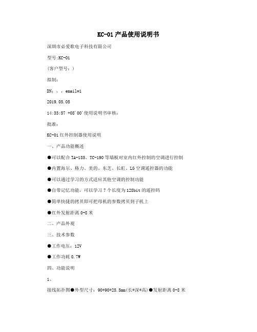
KC-01产品使用说明书深圳市必爱歌电子科技有限公司型号:KC-01(客户型号:)拟制:DN:,,email=12019.05.0514:33:57 +08'00'使用说明书审核:批准:KC-01红外控制器使用说明一、产品功能概述●可以配合TA-185、TC-190等墙板对室内红外控制的空调进行控制●内置海尔、格力、美的、东芝、长虹、LG空调遥控器的功能●可以通过学习的方式适应其他空调的控制功能●自带记忆功能,可以学习7个长度为128bit的遥控码●简单快捷的拷贝即可把母机的参数拷贝到子机上●红外发射距离0-8米二、产品外观三、技术参数●工作电压:12V●工作功耗0.7W四、功能说明1、接线拓扑图●外型尺寸:90*90*25.5mm(长*深*高)●发射距离0-8米2、选择遥控器类型按住确认键,再通电开机,LED屏幕显示“U1”,再短按确认键,LED屏幕显示“01”,表示第一个遥控器,按上下键可以选择不同的遥控器,接上发射头,按确认键可以发射从1到7的遥控码,空调收到之后会做出不同的反应。
设置完成后会自动记忆。
遥控器列表00010203学习型遥控码海尔格力美的040506东芝长虹LG3、学习遥控码按住确认键,再通电开机,LED屏幕显示“U1”,按向下键,屏幕显示“U2”,按确认键,屏幕显示“A1”,这时接上遥控接收头,按一下确认键,“A1”闪烁,表示正在等待接收遥控码,此时按遥控器,屏幕显示“-1”,再显示“A1”,表示学习完成。
再按一下向下键,屏幕显示“A2”,同样的方式可以学习1-7个遥控码,接收完成后数据会自动记忆。
1-7个遥控码说明010205空调关闭制冷26度低风制热20度低风0306制冷23度中风制热23度中风0407制冷20度高风制热26度高风4、拷贝按住确认键,再通电开机,LED屏幕显示“U1”,按向下键,直到屏幕显示“U3”,按确认键,屏幕显示“CO”,进入拷贝模式。
VC-01-Kit 规格书说明书

VC-01-Kit规格书V1.0.0VC- -Kit规格书版本V . .版权 ©文件履历表目录1.产品概述 (4)1.1.特性 (5)2.主要参数 (6)2.1.静电要求 (6)2.2.电气特性 (7)2.3.功耗 (7)3.外观尺寸 (8)4.指示灯及按键说明 (9).管脚定义 (10).原理图 (12).产品相关型号 (13)8.固件烧录方式说明 (13)9.产品包装信息 (14)10.联系我们 (14)免责申明和版权公告 (15)注意 (15)1.产品概述VC-01-Kit是针对VC-01模组设计的开发板,该底板与VC-02-Kit共用。
开发板上集成了CH340C串口转USB芯片,提供基础的调试接口及USB升级接口;唤醒灯及冷暖灯的设计,提供了状态指示及控制指示,且方便调试简单的控制功能。
VC-01是深圳市安信可科技有限公司开发的一款低成本纯离线语音识别模组。
该模组使用云知声推出的语音芯片US516P6,在语音识别技术上不断优化和创新算法,离线识别算法与芯片架构深度融合,为客户提供超低成本的离线语音识别方案,可广泛且快速应用于智能家居,各类智能小家电,86盒,玩具,灯具等需要语音操控的产品。
US516P6芯片采用32bit RSIC架构内核,并加入了专门针对信号处理和语音识别所需要的DSP指令集,支持浮点运算的FPU运算单元,以及FFT加速器。
VC-01支持150条本地指令离线识别,支持RTOS轻量级系统,具有丰富的外围接口,以及简单友好的客制化工具。
图1US516P6芯片架构图1.1.特性内核32bit RISC内核,运行频率240MHz支持DSP指令集以及FPU浮点运算单元FFT加速器:最大支持1024点复数FFT/IFFT运算,或者是2048点的实数FFT/IFFT 运算云知声定制化语音算法算子存储内置242KB高速SRAM内置2MB FLASH音频输入输出灵活配置支持 . / . / . V IO支持1路模拟Mic输入,SNR≥94db支持双声道DAC输出支持中英文语音指令供电和时钟支持5V电源输入内置5V转3.3V,3.3V转1.2V LDO为芯片供电RC 12MHz时钟源和PLL锁相环时钟源内置POR(Power on Reset),低电压检测和看门狗外设所有GPIO均可配置为外部中断输入和唤醒源1个全双工UART最高速率3Mbps。
K CU01 主控制器模块使用说明书
HOLLiAS MACS -K系列模块2014年5月B版HOLLiAS MAC-K系列手册- K-CU01 主控制器模块使用说明书重要信息危险图标:表示存在风险,可能会导致人身伤害或设备损坏件。
警告图标:表示存在风险,可能会导致安全隐患。
提示图标:表示操作建议,例如,如何设定你的工程或者如何使用特定的功能。
目录1.概述 (1)2.接口说明 (2)2.1主控单元结构示意图 (2)2.2底座接口说明 (4)2.3地址跳线 (8)2.4IO-BUS (11)3.状态灯说明 (12)4.其他特殊功能说明 (14)4.1短路保护功能 (14)4.2诊断功能 (15)4.3冗余功能 (15)4.4掉电保护 (16)5.工程应用 (18)5.1底座选型说明 (18)5.2应用注意事项 (18)6.尺寸图 (19)6.1K-CU01尺寸图 (19)6.2K-CUT01尺寸图 (19)7.技术指标 (20)7.1K-CU01主控制器模块 (20)7.2K-CUT01 4槽主控器底座 (21)K-CU01主控制器模块1.概述K-CU01是K系列硬件的控制器模块,是系统的核心控制部件,主要工作是收集I/O模块上报的现场数据,根据组态的控制方案完成对现场设备的控制,同时负责提供数据到上层操作员站显示。
控制器基本功能块主要包括系统网通讯模块、核心处理器、协处理器(IO-BUS主站MCU)、现场通讯数据链路层、现场通讯物理层、以及外围一些辅助功能模块。
K-CU01控制器模块支持两路冗余IO-BUS和从站I/O模块进行通讯,支持两路冗余以太网和上位机进行通讯,实时上传过程数据以及诊断数据。
可以在线下装和更新工程,且不会影响现场控制。
K-CU01控制器模块支持双冗余配置使用。
当冗余配置时,其中一个控制器出现故障,则该控制器会自动将本机工作状态设置为从机,并上报故障信息;若作为主机出现故障,则主从切换;若作为从机出现故障,则保持该状态。
蓝牙开关使用说明V1.01一.模块介绍

蓝牙开关使用说明V1.01一.模块介绍蓝牙继电器开关模块的功能为通过蓝牙主机设备(如电脑,手机)连接模块后进行无线开关动作。
命名规则如下:ZL—RC NN XZL为卓兰的缩写,RC是继电器控制模块。
NN是继电器的路数,一路为01,二路为02,十路为10.X为序号,第一款产品为A,第二款为B。
2路继电器ZL-RC02D性能参数如下:输入电压(模块供电电压):6-24V和5v两种接口蓝牙版本:蓝牙4.0BLE(苹果、安卓手机通用)。
开关路数:2路。
开关电气参数:10A,交流直流都可以控制。
加密特性:8位软件密码。
静态电流:15mA。
尺寸:61*60mm完整设备为图1所示。
右侧有2个电源接口,二选一即可。
左侧为继电器控制接口,2个3P接线柱分别是2路继电器开关,每一路的中间端口是公共端,在继电器未吸合状态下,公共端与常闭端短路连通。
继电器吸合后公共端与常开端短路连通,从而实现开关动作。
二、使用说明1.首先通过12v输入接口或者5v输入接口给模块上电,上电后模块的灯会闪烁,注意电源正负极,如果接入电源后3s灯还没有闪烁,请立即拔下电源,查看是否接反,防止烧坏。
2.手机软件操作说明:安卓手机操作:1)安装手机软件,安卓软件操作界面如下图,进入主界面,点击scan按钮,扫描到设备,点击设备名称连接后,选择爱贝智控进入控制界面。
软件是我们公司通用软件,适用于公司多种产品,包含了4路继电器控制和3路LED的PWM调光控制,ZL-RC02D只有2路继电器可用,没有LED灯控的操作。
2)设置设备的密码,点击设置密码,设备的初始密码是12345678。
3)设置好密码后点击1路开关和2路开关的按钮可进行继电器通断操作。
4)如果需要更改软件密码,那么可用点击设置新密码按钮,设置好密码后点击确认。
目前ZL-RC02D还不支持修改名称,ZL-RC02B支持。
以上就是我们demo的软件操作,如果想自己开发软件可以根据指令集进行相应的操作。
蓝牙模块使用说明书
蓝牙模块使用说明一、模块简介:1、芯片简介该蓝牙模块采用台湾胜普科技有限公司的BMX-02X模块为核心,它采用CSR BLUEcore4-External芯片并配置8Mbit的软件存储空间,成本低,使用方便。
CSR BlueCore4是英国Cambridge Silicon Radio(CSR)公司日前推出的第四代蓝牙硅芯片。
这种硅芯片用于蓝牙技术推广小组(SIG)推出的增强数据传输率(EDR)蓝牙。
CSR的BlueCore4的数据传输率将比现有的v 1.2蓝牙装置快三倍,并且使蓝牙移动电话或手机的耗电量较低。
蓝牙EDR的最大数据传输率为每秒2.1兆比特,而目前v1.2标准传输率则为每秒721千比特。
传输率的提高意味着对一个特定量的数据来说,EDR无线电的工作将比v1.2无线电快三倍,从而减少耗电量,大大有利于依赖蓄电池的移动设备。
CSR BlueCore4完全能与现有蓝牙v1.1和v1.2装置兼容。
蓝牙EDR用一种相移键控(PSK)调制模式取代标准传输率的Gaussian频移键控(GFSK),实现更高的数据传输率。
CSR BlueCore4正在以两种形式提供——一种用于外部“快闪”存储器,一种用于掩模ROM。
BlueCore4-External以一种8×8mm BGA(球形格栅矩阵)封装提供,是十分灵活的解决方案,能够适应迅速更新的市场。
例如,由于BlueCore是目前可以得到的唯一能够支持蓝牙v1.2规格的所有强制和可选功能的硅芯片,BlueCore4-External为PC应用程序提供了理想的解决方案,使它们得益于以三倍速度的传输率无线传输文件,或者同时操作多个高需求的蓝牙链路。
鉴于蓝牙固件安装在芯片只读存储器上,CSR BlueCore4-ROM 的成本较低,占用面积小得多(在小片尺寸包装中为3.8×4mm,在与BC2-ROM和BC3-ROM引脚兼容的BGA中为6×6mm)。
KC-01产品使用说明书

KC-01产品使用说明书深圳市必爱歌电子科技有限公司型号:KC-01(客户型号:)拟制:DN:,,email=12019.05.0514:33:57 +08'00'使用说明书审核:批准:KC-01红外控制器使用说明一、产品功能概述●可以配合TA-185、TC-190等墙板对室内红外控制的空调进行控制●内置海尔、格力、美的、东芝、长虹、LG空调遥控器的功能●可以通过学习的方式适应其他空调的控制功能●自带记忆功能,可以学习7个长度为128bit的遥控码●简单快捷的拷贝即可把母机的参数拷贝到子机上●红外发射距离0-8米二、产品外观三、技术参数●工作电压:12V●工作功耗0.7W四、功能说明1、接线拓扑图●外型尺寸:90*90*25.5mm(长*深*高)●发射距离0-8米2、选择遥控器类型按住确认键,再通电开机,LED屏幕显示“U1”,再短按确认键,LED屏幕显示“01”,表示第一个遥控器,按上下键可以选择不同的遥控器,接上发射头,按确认键可以发射从1到7的遥控码,空调收到之后会做出不同的反应。
设置完成后会自动记忆。
遥控器列表00010203学习型遥控码海尔格力美的040506东芝长虹LG3、学习遥控码按住确认键,再通电开机,LED屏幕显示“U1”,按向下键,屏幕显示“U2”,按确认键,屏幕显示“A1”,这时接上遥控接收头,按一下确认键,“A1”闪烁,表示正在等待接收遥控码,此时按遥控器,屏幕显示“-1”,再显示“A1”,表示学习完成。
再按一下向下键,屏幕显示“A2”,同样的方式可以学习1-7个遥控码,接收完成后数据会自动记忆。
1-7个遥控码说明010205空调关闭制冷26度低风制热20度低风0306制冷23度中风制热23度中风0407制冷20度高风制热26度高风4、拷贝按住确认键,再通电开机,LED屏幕显示“U1”,按向下键,直到屏幕显示“U3”,按确认键,屏幕显示“CO”,进入拷贝模式。
KCU-01 USB 模块用户手册说明书
KCU-01USB ModuleTel : + 886-7-8121771Fax : + 886-7-8121775URL : ______________________________________________________________________________________ 2SECTION 1 : INTRODUCTIONThe KCU-01 is the USB module that is designed to enable the Kutai Electronics genset controllers (AMF-10, GCU-100, GCU-3000) to be operated and monitored remotely.Via the designated operation software (Please reference from KCU-01 software user manual) user can program and change parameters remotely instead of accessing program through the controller in person.In the remote operation, when Connecting KCU-01 via two-wire telephone line, an additional USB modem is required to connect to the KCU-01 USB port. The remote operating PC will also need to be equipped with modem / USB modem MAIN CHARACTERISTICS :● The KCU-01 software interface is user friendly which makes it easy for user to monitor and change program setting remotely. ● When operating on site (Local operation mode), user can connect the KCU-01 USB port to the PC via USB harness or connect to an USB modem for remote operation ● When operating KCU-01 in remote operation mode, if no data is transmitted within 40 seconds after connection then the module will automatically disconnect. ● Supports Logo Image downloads for ATS-PLC when installed the “Image Transfer ” software .SECTION 2 : DIMENSIONSECTION 3 : INSTALLATIONDisconnect controller power source and follow the below illustrations to complete the installation of KCU-01.Step 1:Remove slot cover from the back ofcontroller.Step 2:Insert KCU-01 into the designated slot.Step 3:Tighten the screw.______________________________________________________________________________________3Step 4:Start up the controller and operate through the controller front panel and enter system setting to program corresponding startup settings (Remote operation activation).The KCU-01 currently supports AMF-10, GCU-100, GCU-3000, ATS-22, ATS-33, ATS-34 and ATS-PLC etc. controllers. The followings are the basic description of operation settings. For more detail information, please reference from the controller ’s operation manual.Remark :If remote access is programmed to “Remote access cancelled" or "turn OFFATS-PLC communication interface “, user can only execute monitoring and changing system parameter and unable to execute controller command.SECTION 4 : OPERATIONFor more information on KCU-01 Data link status LED indicator, please reference from chapter 5.Example 01:On site / Local operation mode.Controller endExample 02:Remote Operation mode.USB MODEMHost ComputerSECTION 5 : STATUS INDICATOR & TROUBLESHOOTINGS5.1 Through the KCU-01 LED status indicator user can understand the current operating status5.2 Trouble shootingsLED Indicator______________________________________________________________________________________ 4。
KC01 随机手册
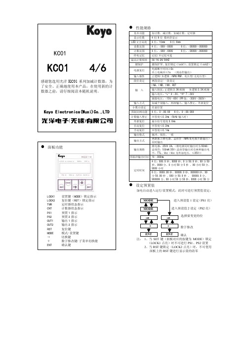
E017
二 错
段
时
间
设
定
出
修正设置
进入 PS1 MODE 键 切 换 到 设置 PS2
注:当出现故障代码显示时,在确认代码后按下 ENT 键显示将进入 修改状态等候解决。
2.上电时应保证电源的稳定,并持续 2 秒以上,此过程中电源的波 动可能导致输出不确定,甚至导致计数器工作不正常。二次上电应 在掉电 2 秒以后,以保证计数器的正常复位。在上电 2 秒内,频繁 的上电、掉电以及电压波动有可能会非正常修改设置,故上电前应 确保电路连接正常。 3.计数器 0V 和 COM 端在内部是相连的,端子台上只有 COM 端。 4.未使用的端子请勿作它用。即使个别型号并无相应功能,相应端 子也不可作它用(如 DC 型无 AC 输入,但 AC 端子也不可移做它用)。 5、设置时改变数值一定要按下 ENT 确认,否则修改不会被保存, 在确认保存之前如果掉电,修改也不会被保存。 6、+24V 端子为双向口,即当使用 AC 输入时,+24V 端子为输出口, 此时+12 端子同时输出。当不使用 AC 电源或使用的是 DC 型产品, +24V 端子为输入口,此时+12 端子没有输出。
10~999ms
4 位:999.9 秒、9999 秒、9 分 59.9 秒、99 分 59 秒、9999 分、9 小时 59 分 5 秒 、99 小时 59 分、 9999 小时 6 位:9999.99 秒、99999.9 秒、999999 秒、99 分 59.99 秒 、999 分 59.9 秒 、 99999.9 分、 999999 分、99 小时 59 分 59 秒、9999 小时 59 分
设置键(MODE)锁定指示 复位键(RST)锁定指示 定时器状态指示 计数器状态指示 预置 1 指示 预置 2 指示 输出 1 指示 输出 2 指示 复位键 模式/设置键 切换键 数字修改键/子菜单切换健 确认键
KCC1智能部件说明书

1 概述1.1KCC1型系列智能I/O部件,是KJ50型PROMOS监控系统中的主要产品,是PROMOS系统输入输出信息的转接设备,共有四个输入输出端口,每一端可连接一路传感器输入和一路执行元件的输出,不能单独使用,只能与PROMOS系统配套使用,按与外部设备相联的不同要求有五种方式。
KCC1型系列智能I/O部件,采用插头座连接。
KCC1A型智能I/O部件,采用接线端子连接。
KCC1B型智能I/O部件是在两个输出口中附加了SKR安全信号的控制部件。
KCC1C型智能I/O部件是在四个输出口中都加SKR安全输出信号的控制部件。
SKR安全输出信号,从硬件方面保证紧急停车的作用更加安全有效。
KCC1D型是以多块智能I/0部件为基础的灵活组合。
本产品适用于煤矿井下的有甲烷和煤尘爆炸性危险的环境中,其防爆型式为:矿用本质安全型。
防爆标志为:ExibI(150℃)。
其关联设备为KDW10型矿用直流稳压电源。
(隔爆兼本安型)其配接设备为:KJF21型控制器KJJ10型控制接口KJK3型系列辅助控制器KTK1型系列扩音电话KPG3型系列急停开关KDF1型系列线路终端KPA1型按钮KPG2型开关KZD2型电控阀等等以上设备全部为本质安全型。
1.2型号及其含义KC C 1变型序号A-D登记序号模、开I/O混合组件矿用信息传输装置及组件其中变型序号:A为引线端子式B为两路接点输出和两路安耦合接点输出C为四路接点输出和四路安耦合接点输出D为多块智能I/O部件为基础的各种组合7-21.3 使用环境及工作条件在下列环境条件下KCC1型系列智能I/O 部件应能正常工作: -工作环境温度:0-40℃;-平均相对湿度:不超过96%(+25℃); -大气压力:(80-106)kPa ;-有甲烷和煤尘爆炸性危险的矿井环境中;-允许有溅水但无破坏绝缘的腐蚀性气体的矿井中; -无剧烈振动和冲击的地方。
2结构特征 2.1 结构特征KCC1型系列智能I/O 部件的外壳是由钢板焊接而成的, 壳体的最小厚度均不小于3mm ,其中的零、部件有防锈防蚀处理,紧固件有防松动的措施,其中KCC1型系列的接线方式为插头座,KCC1A-D 型带有接线腔,腔内设有端子排,采用电缆引入装置,产品外形结构见图1。
最新版蓝牙模块说明书

蓝牙模块软件说明书目录1.低功耗蓝牙(BLE)4.1 模块简介 (1)1.1. 功能简介 (1)1.2. 主要功能特点 (1)1.3. 模组电气特性 (2)1.4. 模组蓝牙功耗对照表 (2)1.5. 工作模式示意图 (3)1.6. 模块脚位图 (4)1.6.1.模块 7x7 脚位图 (4)1.6.2.模块 5x5 脚位图 (6)1.7. 引脚功能 (6)1.7.1 模块 7x7 引脚功能 (6)1.7.2.模块 5x5 引脚功能 (8)2.模块软件指令说明 (11)2.1. 命令表 (11)2.2. SPI 软件命令格式说明 (15)2.2.1. SPI 写命令 (15)2.2.2. SPI 读命令 (15)2.3. UART 命令格式说明 (16)2.3.1. UART 读写命令 (16)2.3.2. UART 接收 BLE 数据 (17)2.4. 蓝牙软件读写说明 (17)2.4.1. 模块 UUID 说明 (17)2.4.2. 模组蓝牙通道操作软件说明 (17)2.5. 命令说明 (18)3.APP 工具使用说明 (35)3.1.APP 读取及设置模组参数 (36)3.2.接收发送透传数据 (37)4.联系我们 (38)5.文件修订说明 (39)1. 低功耗蓝牙( BLE )1 4.1 模块简介1.1. 功能简介蓝牙模块支持从机模式。
支持桥接模式(透传模式)和直驱模式。
模块通过初始设置后会自动进行广播,已打开特定 APP 的手机会对其进行扫描和对接,成功之后便可以通过 BLE 协议对其进行控制。
桥接模式:用户 CPU 可以通过模块的通用 UART 或 SPI 和移动设备进行双向通讯,用户也可以通过特定的指令,对模块的蓝牙参数进行管理控制。
用户数据的具体含义由上层应用程序自行定义。
移动设备可以通过 APP 对模块进行写操作,写入的数据将通过 UART 或 SPI 发送给用户的 CPU。
模块收到来自用户 CPU数据包后,将自动转发给移动设备。
蓝牙模块评估板数据表说明书

DKWF121 – WF121-A 802.11 B/G/N MODULE EVALUATION BOARDPRELIMINARY DATA SHEETWednesday, 16 May 2012Version 0.5Copyright © 2000-2012 Bluegiga TechnologiesAll rights reserved.Bluegiga Technologies assumes no responsibility for any errors which may appear in this manual. Furthermore, Bluegiga Technologies reserves the right to alter the hardware, software, and/or specifications detailed here at any time without notice and does not make any commitment to update the information contained here. Bluegiga’s products are not authorized for use as critical c omponents in life support devices or systems.The WRAP, Bluegiga Access Server, Access Point and iWRAP are registered trademarks of Bluegiga Technologies.The Bluetooth trademark is owned by the Bluetooth SIG Inc., USA and is licensed to Bluegiga Technologies. All other trademarks listed herein are owned by their respective owners.VERSION HISTORYTABLE OF CONTENTS1Product description (5)2Ordering Information (6)3Board Description (7)3.1WiFi Module (7)3.2Crystals (7)3.3Configurable I/O Ports (7)3.4Bluetooth Coexistence (8)3.5LEDs and Buttons (8)3.6USB Connections (9)3.7Board Power (10)3.8Current Measurement Point J13 (10)3.9VDD_PA Selection Header J7 (10)3.10Ethernet (11)3.11Programming Connections (11)3.12Debug SPI Interface (12)3.13Prototyping Area (12)4Board layout (13)5Contact Information (14)1 Product descriptionDESCRIPTIONDKWF121 is intended for evaluating the WF121 Wi-Fi module and as a basis for product development. The board contains connectors for easy development with a PC using the main host connections, USB and UART through a USB converter. Also present are headers for all the GPIO pads connected around a prototyping area for easy connection of pin headers with custom pinouts, sensors etc.The WF121 is a self-contained Wi-Fi module providing a fully integrated 2.4GHz 802.11 b/g/n radio and a 32-bit microcontroller (MCU) platform, making it an ideal product for embedded applications requiring simple, low-cost and low-power wireless TCP/IP connectivity. WF121 also provides flexible interfaces for connecting to various peripherals. WF121 allows end user applications to be embedded onto the on-board 32-bit microcontroller using a simple Bluegiga BGScript TM scripting language. This cuts out the need of an external MCU and allows the development of smaller and lower-cost products. However WF121 can also be used in modem-like mode in applications where the external MCU is needed.With an integrated 802.11 radio, antenna, single power supply, and regulatory certifications, WF121 provides a low-risk and fast time-to-market for applications requiring Wi-Fi connectivity. This co mbined with Bluegiga’s excellent customer service will turn your Internet-of-Things applications into reality. KEY FEATURES:-USB or UART host connection-USB converter for the UART-Can be powered through USB-Current measurement voltage output -Prototyping areaPHYSICAL OUTLOOK:2 Ordering InformationConfidentialConfidential 3Board Description3.1 WiFi ModuleDKWF121 contains a WF121-A module variant, with an internal chip antenna.3.2 CrystalsThere are two crystals assembled on DKWF121, an 8MHz crystal for the WF121 CPU clocking and a32.768kHz crystal for the CPU real time clock. The 8MHz crystal is needed when the WF121 USB connection is used, otherwise it is not essential. The 32kHz crystal is also optional, and if extra GPIO are needed, the 0ohm resistors connecting the crystals to the module can be removed and moved to connect the pin headers and prototyping area pads to the module pads. The pads are not connected to the pin headers by default as crystal connections are always sensitive to noise.3.3Configurable I/O PortsAll the GPIO pads available on the WF121 are routed to pin headers for easy connection to other boards or a logic analyzer. All the signals are also available on through-hole pads on the edges of the board prototyping area for easy development prototyping.The GPIO signals associated with the crystals are routed but not connected due to the presence of the crystals, but if required the crystals can be removed and the associated 0ohm resistors moved to connect the signals to the headers.The signals shared for other functions like the ICSP programming interfac e, JTAG, UART’s and Ethernet should not be driven by externally connected outputs when the mentioned functions are used to avoid damage. The UART and Ethernet signals are disconnected when the associated on-board chips are disabled with the on-board switches.The USB pins are by default disconnected from the pin headers, but can be connected by adding two jumpers to the specific header.3.4 Bluetooth CoexistenceIndustry standard 2-wire and 3-wire, as well as Unity-3, Unity-4, Unity-3e coexistence schemes are supported as well as the Unity+ -extension, and the associated signals are available. The PIO pads can be configured for these functions among others. A U.FL connector is also present for antenna sharing using the module internal RF switch. As only 4 GPIO signals can be used for coexistence, antenna sharing in practice requires the use of the CSR proprietary Unity-3e or 3e+ scheme.3.5 LEDs and ButtonsThere are five LEDs and five pushbuttons on the DKWF121. One button is for module reset and one LED indicates that the module has a power supply present, while the other four LEDs and buttons are available for development purposes. The LEDs are buffered with MOSFETs and the buttons are open when unpressed, allowing the connected GPIO lines to be used for other purposes without disconnecting the LEDs or buttons.Confidential3.6USB Connectionsoperating systems with either inbuilt or automatically installed drivers.ConfidentialConfidential No separate connectors for SPI host connections are provided as there is no standard connector or pinout, but the signals are available on the pin headers and pads on the prototyping area edge for easy soldering of a connector with a custom pinout.3.7Board PowerDKWF121 can be powered by several sources.∙ Both USB connectors can be used as the power supply input ∙ A two-pin header∙The signal pin headers and prototyping area connections have power connectionsNote: if the on-board WF121 module does not contain firmware that operates the native USB connection, the module cannot request an increase to the USB default current limit of 100mA. Although not all USB host systems implement it, the USB specification states that the host should limit the current output to 100mA unless an increase is requested, and using the module with high transmit duty cycles may cause the USB host to go into current limit, possibly causing the module to crash. It is preferred to power the board through the USB/UART-converter connector, the converter chip will automatically request for an increased current limit. The board contains a switch mode converter that converts the 5V input to the 3.3V supply required by the module. The converter is specified for output currents up to 600mA, allowing up to 200mA to be drawn for powering customer applications.The module operates down to 2.7V, but the current measure output and USB host functionality require a regulated 5V input. The header and the USB connectors also have series schottky diodes, increasing the minimum input voltage slightly. The 5V power connections in the prototyping area and the associated pin headers do not have series diodes. The diodes allow connection of a USB host together with a separate power supply without risk of damage.3.8 Current Measurement Point J13Header J13 contains a jumper that connects the switch mode regulator to the module 3.3V supply pads. The jumper can be removed and the average current consumption of the module can be measured with a multimeter or a series resistor can be inserted for measuring the momentary current consumption of the module with an oscilloscope. Note that for average consumption measurement of anything else besides sleep current a fast RMS multimeter is needed due to the pulsed nature of the consumption.Removing the jumper also allows separation of the module supply lines from the regulator output, for example when using an external regulator to supply the 3.3V voltage to the module is desired.3.9 VDD_PA Selection Header J7WF121 has two power supply inputs, VDD_3.3V (VDD_3.3V_MOD line on the schematic) and VDD_PA. The VDD_3.3V pad supplies the internal processor and has a voltage range of 2.3V to 3.6V. The VDD_PA pad supplies the internal WiFi-circuitry through a switch mode converter and the WiFi power amplifier directly. TheVDD_PA line can operate with input voltages between 2.7V and 5.5V, though the power consumption of the power amplifier will grow in direct proportion to the input voltage. The separate supply however allows direct connection to a lithium-ion battery, with just a small linear regulator limiting the supply voltage for the processor side.A jumper at header J7 usually connects VDD_PA to the board 3.3V switch mode converter output. The jumper can be moved to the alternate position to supply the VDD_PA line directly from the 5V supply rail, for example for connecting directly to a lithium battery either through the power input header or through the prototyping area connections.3.10EthernetThe board contains a 10/100Mbps Ethernet PHY with all the associated components, connected to the module internal Ethernet MAC with an RMII interface. The PHY can be fully powered off and disconnected from the GPIO lines using switch SW1, allowing the GPIO lines to be used for other functions. The Ethernet interface is not yet supported by the Bluegiga software.3.11Programming ConnectionsDKWF121 contains two connectors that allow direct programming of the WF121 internal processor. The Microchip proprietary ICSP bus allows programming the full firmware image using a Microchip or third party programming adapter. The pin header installed on the DKWF121 has a pinout suitable for use with the low-Confidentialcost PicKit3 programming tool from Microchip. A JTAG connection is also available for basic boundary scans and device programming. The JTAG does not support full device testing and debugging.The primary means of uploading application data is through a host connection through the Bluegiga boot loader. The programming connections should not be needed unless the internal boot loader is overwritten by the application.3.12 Debug SPI InterfaceA header is provided for the module debug bus for certification RF testing. Access to internal settings and test modes is available using a CSR compatible SPI adapter and UniTest-software.For more information contact Bluegiga technical support.3.13 Prototyping AreaDKWF121 contains an array of through plated holes with wide pads with a 2.54mm raster for easy addition of carrier boards, through-hole components and pin headers with a custom pinout. Also present is a smaller array of pads with no holes using 1.27m raster for connecting SMD components like sensors, regulators etc during system development.All GPIO signals are routed to the prototyping area edges, though some of them are not by default connected due to function multiplexing. See other chapters for detailed descriptions of these signals.Also present on the pin headers and pads around the prototyping area are several supply voltage rails present on the board. These can be used for powering external circuitry, or for powering the module with external power sources. The uppermost and lowest rows of pads are connected to ground.Confidential4 Board layoutConfidential5 Contact InformationSales:******************Technical support:********************Orders: *******************WWW: www.bluegiga.hkHead Office / Finland:Phone: +358-9-4355 060Fax: +358-9-4355 0660Sinikalliontie 5A02630 ESPOOFINLANDPostal address / Finland:P.O. BOX 12002631 ESPOOFINLANDSales Office / USA:Phone: +1 770 291 2181Fax:+1 770 291 2183Bluegiga Technologies, Inc.3235 Satellite Boulevard, Building 400, Suite 300Duluth, GA, 30096, USASales Office / Hong-Kong:Phone: +852 3182 7321Fax:+852 3972 5777Bluegiga Technologies, Inc.19/F Silver Fortune Plaza, 1 Wellington Street,Central Hong KongConfidential。
蓝牙模块说明书
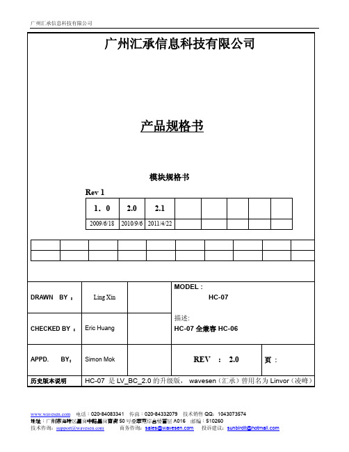
line
10 Bi-Directional Programmable input/output
line
PIO0
PIO1
PIO2 PIO3 PIO4
23 Bi-Directional Programmable input/output
RX EN
line, control output for
LNA(if fitted)
可以外部供电 1.8V
默认为内部供电 1.8V
PCM_ 8 SYNC
Bi-Directional
电话:020-84083341 传真:020-84332079 技术销售 QQ:1043073574
地址:广州市海珠区昌岗中路昌岗南街 50 号叠翠苑综合楼首层 A016 邮编:510260
CMOS output, tri-stable with weak internal
pull-up
CMOS input with weak internal pull-down
CMOS input with weak internal pull-down
CMOS output, Tri-stable with weak internal
线路处理线路中
低功耗 高性能无线收发系统 低成本 应用领域
蓝牙车载免提 蓝牙 GPS 蓝牙 PCMCIA , USB Dongle 蓝牙数据传送 软件 CSR
3.引脚定义和功能
电话:020-84083341 传真:020-84332079 技术销售 QQ:1043073574
line Programmable input/output
line Programmable input/output
蓝牙模块固件升级说明书 - 中文
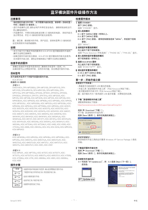
注意事项各机型的升级文件不同。
关于需要升级的机型,请参照<目标机型>·中的<连接的CD接收机>。
进行升级操作之前,请务必将汽车停在安全地点。
请保持发动机运行,·防止蓄电池耗尽。
升级操作时,不得关闭发动机或切断CD接收机的电源。
否则升级无·法正常完成,并且CD接收机将可能无法使用。
注: 请注意,诸如配对的手机、用户设定、语音标签等CD接收机的设定将因软件升级而被删除。
说明本文介绍了为了满足手机的要求对KCA-BT200蓝牙模块固件升级的·操作方法和注意事项。
如果在固件升级中发生错误,KCA-BT200蓝牙模块将可能无法使用。
·在对固件升级之前,请务必详细阅读以下操作方法和注意事项。
检查手机的固件请确认连接的手机型号是否列在[兼容的手机型号一览表]中。
如果目前可以正常使用手机,没有任何问题,则无需进行固件升级。
目标型号本升级程序适用于下列型号装置的固件升级。
KCA-BT200连接的CD接收机分组 E-1DNX210EX, DPX-MP2090U, DPX-MP2100, DPX-MP3110, DPX-MP3110S, DPX-MP4110, DPX-MP4110S, DPX-MP5100U, DPX-MP5110U, DPX-MP7090U, DPX302, DPX501, DPX501U, DPX502,DPX502U, DPX502UY, DPX701, DPX701U, KDC-MP2035, KDC-MP235, KDC-MP238, KDC-MP3035, KDC-MP335, KDC-MP338, KDC-MP4036AX, KDC-MP4039, KDC-MP408U, KDC-MP438U, KDC-MP439, KDC-MP5033U , KDC-MP5039U, KDC-MP532U, KDC-MP5539U, KDC-MP6036, KDC-MP632U, KDC-MP7090U, KDC-MP832U, KDC-W3537, KDC-W3537A, KDC-W3537AY, KDC-W3537G, KDC-W3537GY, KDC-W3541A, KDC-W3541AY, KDC-W3541G, KDC-W3541GY, KDC-W4037, KDC-W4037Y, KDC-W4041A, KDC-W4041G, KDC-W4041W, KDC-W4141AY, KDC-W4141GY, KDC-W4141WY, KDC-W5041UA, KDC-W5041UG, KDC-W5137, KDC-W5137Y, KDC-W5141U, KDC-W5141UAY, KDC-W5141UGY, KDC-W5534U, KDC-W5541U, KDC-W5641UY, KDC-W6534U, KDC-W7534U, KDC-W7534UY, KDC-X492, KDC-X590, KDC-X7533U, KDC-X890, KDC-X9533U, KDV-412, KDV-5234, KDV-MP6333, KDV-MP6433分组 E-2KDC-MP4036U, KDC-MP435U, KDC-MP436U, KDC-MP5036U, KDC-MP535U, KDC-W4537U, KDC-W4537UA, KDC-W4537UAY, KDC-W4537UG, KDC-W4537UGY, KDC-W4737U , KDC-W4737UY, KDC-W6537U, KDC-W6537UY, KDC-X491, KDC-X591分组 E-3KDC-MP635 , KDC-MP735U, KDC-W7037, KDC-W7037Y, KDC-W7537U, KDC-W7537UY, KDC-W9537U, KDC-W9537UY, KDC-X7006, KDC-X7006U, KDC-X791, KDC-X8006U, KDC-X891, KDC-X9006U, KDC-X991检查固件版本选择STANDBY1按下 [SRC] 按钮。
汇承HC-02V1.1蓝牙双模串口模块使用规格书
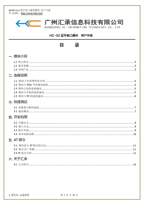
3.1 参数架与模块连接……..………………………………………………………………………………………………………………….…………………...7 3.2 通讯测试……..……………………………………………………..……………………………………………………………………. ………………………..7
① 使用参数架连接模块与电脑,选择对应的模块
型号;
② 如不清楚模块波特率,可按“模块波特率查询”
按钮查询当前模块的波特率,默认为 9600;
③ 发送 AT(或点击 HID 软件右上角的测试指令按
钮),返回 OK,即为模块工作正常;
④ 其他 AT 指令请参照 5.3。
汇聚信息 承载梦想
第 7 页 共 14 页
参数值 27*13mm
2Mbps 内置 PCB 天线
30mA -85dBm@2Mbps
10%~90% -40℃~+85℃ -25℃~75℃
型号
通信协议 工作频段 通信距离 空中速率
HC-06-USB 蓝牙 2.0 2.4G10 米Leabharlann 2MbpsHC-05
蓝牙 2.0 2.4G
10 米
2Mbps
HC-06 HC-08
汇聚信息 承载梦想
第 5 页 共 14 页
HC-02 V1.1 蓝牙串口通信模块 用户手册 官方网址:
2.5 模块与 PC 的连接
HC-02 连接电脑需借助 HC-06-USB 蓝牙虚拟串口与电脑相连。 HC-02 可以连接电脑的自带蓝牙设备进行通讯。
汇聚信息 承载梦想
汇聚信息 承载梦想
第 8 页 共 14 页
HC-02 V1.1 蓝牙串口通信模块 用户手册 官方网址: 到串口透传模式。
蓝蜙蜆BGM113蓝牙模块无线电路板参考手册说明书

BRD4301A Reference ManualManualThe Blue Gecko family of the Silicon Labs' Bluetooth modules delivers a high-perform-ance, low energy and easy-to-use Bluetooth solution integrated into a small form factorpackage. Blue Gecko Bluetooth modules combine an integrated antenna, a high per-formance Bluetooth transceiver, an energy efficient 32-bit MCU and a ready to useBluetooth software and SDK.The ultra-low power operating modes and fast wake-up times of the Silicon Labs' ener-gy friendly 32-bit MCUs, combined with the low transmit and receive power consump-tion of the Bluetooth radio, result in a solution optimized for battery powered applica-tions.The Silicon Labs fully certified Bluetooth modules and software are designed to help de-velopers accelerate time to market and reduce development costs and compliance risksby providing a versatile, plug-and-play Bluetooth solution.Development and evaluation of the BGM113 Bluetooth module is possible by attachingthe BRD4301A board to the Wireless Starter Kit (WSTK) Mainboard. This gives accessto the WSTK display, buttons and additional features offered by using the available Ex-pansion Boards.Rev. 1.00BRD4301A Radio Board Description 1. BRD4301A Radio Board DescriptionThe BRD4301A Radio Board contains the BGM113 Blue Gecko Bluetooth Module soldered onto a carrier board with two connectors. The connectors on the carrier board are used for attaching the BRD4301A on to a Silicon Labs Wireless Starter Kit Main-board BRD4001A and together these two boards and the software in the BGM113 Module make up the Blue Gecko Bluetooth Module Wire-less Starter Kit.The BGM113 Bluetooth module and the software are designed to help developers accelerate time to market with end-product design projects. This versatile plug-and-play Bluetooth solution also reduces development costs and minimizes compliance risks. The BGM113 Module is ideal for applications requiring Bluetooth connectivity such as used in connected home, health and fitness, wearables and point-of-sale terminal applications. The BGM113 includes an energy friendly ARM Cortex M4 MCU.A major benefit offered by the BGM113 is that no RF or Bluetooth protocol expertise is required. The BGM113 can be used as a periph-eral along with an external host MCU or applications may be embedded into the built-in MCU using the Bluegiga BGScript™ scripting language. Complete standalone solutions may thus be created with minimal need for external components.1.1 BGM113 Module Block DiagramThe BGM113 Module block diagram is illustrated in the figure below.Lowest power mode with peripheral operational:EM0—ActiveEM2—Deep SleepEM1—Sleep EM4—Hibernate EM4—ShutoffEM3—StopFigure 1.1 Block Diagram| Smart. Connected. Energy-friendly.Rev. 1.00 | 12. System SummaryIntegrated Bluetooth radio and energy friendly MCU•Bluetooth 4.1 compliant and upgradeable to Bluetooth 4.2.•TX power up to +3 dBm•RX sensitivity down to -93 dBm•Integrated high-efficiency chip antenna•38.4 MHz Cortex M4 with DSP instructions and floating-point unit for efficient signal processing•256 kB Flash memory•32 kB RAMLow Energy Consumption•8.8 mA TX current @ 0 dBm•8.7 mA RX current•63 μA/MHz in Energy Mode 0 (EM0)• 1.4 μA EM2 Deep Sleep Current (full RAM retention) and CRYO timer running from ULFRCO• 1.1 μA EM3 Stop current (State/RAM retention, RFSENSE disabled)•Wake on Radio with signal strength detection, preamble pattern detection, frame detection and timeoutWide selection of MCU peripherals•12-bit 1 Msamples/s ADC• 2 x Analog comparator•IDAC (current output DAC)•Up to 14 pins connected to analog channels (APORT) shared between analog comparators, ADC and IDAC •14 General Purpose I/O pins with output state retention and asynchronous interrupts•8-channel DMA controller•12-channel Peripheral Reflex System•Hardware Crypto Acceleration with public key support•Protocol Timer tightly coupled to the radio• 2 x 16-bit Timer/Counter• 3 + 4 Compare/Capture/PWM Channels•32-bit Real Time Counter and Calendar•16-bit Low Energy Timer for waveform generation•16-bit Ultra Low Energy Timer/Counter for periodic wake-up from any Energy Mode•16-bit Pulse Counter with asynchronous operation•Watchdog Timer with dedicated RC Oscillator @ 50 nA• 2 x Universal Synchronous/Asynchronous Receiver/Transmitter (UART/SPI/Smart Card (ISO 7816) / IrDA/I2S)•Low Energy UART (LEUART)•I²C interface with SMBus support and address recognition in EM3 StopIntegrated Bluetooth Smart Software•Bluetooth 4.1 compliant•Central and peripheral roles•Up to 8 simultaneous connections•L2CAP, ATT, GAP, SM and GATT•Any GATT based Bluetooth Smart profile•100 kbps throughputFlexible easy to use APIs•BGAPI™ serial protocol API over UART for modem usage•BGLIB™ host API/library which implementing BGAPI serial protocol•BGScript™ scripting language for standalone usage•Profile Toolkit for creating GATT based servicesFree Software Development Kit (SDK)•BGLIB C source code•BGScript development tools•BGScript and BGLIB example applications•Profile Toolkit examples•DocumentationCertifications•Bluetooth qualified (pending)•CE, FCC, IC, Japan and South-Korea (pending)Wide Operating Range•Supply voltage: 1.85 V to 3.8 V with DC/DC bypass mode •Supply voltage: 2.4 V to 3.8 V with DC/DC enabled •Temperature range: -40°C to +85°C3. BRD4301A Connector3.1 BRD4301A Connector Pin AssociationsThe figure below shows the pin mapping on the connector to the radio pins and their corresponding function on the Wireless Starter Kit Mainboard.GNDF9 / PF3 / VCOM_RTS 3v3NC / P36P200Upper RowNC / P38NC / P40NC / P42NC / P44DBG_SWDIO / PF1 / F0NC / F14BUTTON0 / PD14 / F12LED0 / PD14 / F10VCOM_CTS / PF2 / F8DBG_RESET / F4NC / F2NC / F16VCOM_TX / PA0 / F6PTI_DATA / PB12 / F20NC / F18USB_VBUS5VBoard ID SCLGNDBoard ID SDAUSB_VREG F7 / PA1 / VCOM_RX F5 / tied high / VCOM_ENABLE F3 / NCF1 / PF0 / DBG_SWCLK P45 / NCP43 / NC P41 / NC P39 / NC P37 / tied high / SENSOR_ENABLE F11 / PD15 / LED1F13 / PD15 / BUTTON1F15 / NC F17 / NCF19 / PB13 / PTI_FRAME F21 / NC GNDVMCU_INEXP3 / PF2 / P0P201Lower RowEXP5 / PF3 / P2NC / P4NC / P6GNDVRF_INP35 / NC P7 / PD13 / EXP10P5 / PB13 / EXP8P3 / PB12 / EXP6P1 / PB11 / EXP4P33 / NC P31 / NC P29 / NC P27 / PF1P25 / PF0P23 / PD15P21 / PD14P19 / NC P17 / NC P15 / NC P13 / PC10 / EXP16P11 / PA1 / EXP14P9 / PA0 / EXP12NC / P34NC / P32NC / P30NC / P28NC / P26NC / P24NC / P22NC / P20NC / P18NC / P16NC / P14EXP15 / PC11 / P12NC / P10NC / P8Figure 3.1 Radio Board Connectors3.2 BRD4301A Connector TypeBRD4301A contains two dual-row, female socket, 0.05" pitch polarized connectors (P/N: SFC-120-T2-L-D-A-K-TR) which provide the interface to the Wireless Starter Kit Mainboard. The Mainboard has the corresponding male header pin connectors (P/N: TFC-120-02-F-D-LC-ND).BRD4301A ConnectorMechanical Details 4. Mechanical DetailsModule board is illustrated in the figures below.The BGM113 BluetoothFigure 4.1 BRD4301A Top View Array Figure 4.2 BRD4301A Bottom ViewRev. 1.00 | 5Board Revision History and Errata 5. Board Revision History and Errata5.1 Revision HistoryRadio Board revision is printed on the backside of the BRD4301A Radio Board.Table 5.1. Radio Board Revision History5.2 ErrataRev. A00No known errata for this board revision. | Smart. Connected. Energy-friendly.Rev. 1.00 | 6Document Revision History 6. Document Revision HistoryRevision 1.002015-07-08Initial document revision.Silicon Laboratories Inc.400 West Cesar Chavez Austin, TX 78701USASmart.Connected.Energy-Friendly .Products/productsQuality /qualitySupport and CommunityDisclaimerSilicon Laboratories intends to provide customers with the latest, accurate, and in-depth documentation of all peripherals and modules available for system and software implementers using or intending to use the Silicon Laboratories products. Characterization data, available modules and peripherals, memory sizes and memory addresses refer to each specific device, and "Typical" parameters provided can and do vary in different applications. Application examples described herein are for illustrative purposes only. Silicon Laboratories reserves the right to make changes without further notice and limitation to product information, specifications, and descriptions herein, and does not give warranties as to the accuracy or completeness of the included information. Silicon Laboratories shall have no liability for the consequences of use of the information supplied herein. This document does not imply or express copyright licenses granted hereunder to design or fabricate any integrated circuits. The products are not designed or authorized to be used within any Life Support System without the specific written consent of Silicon Laboratories. A "Life Support System" is any product or system intended to support or sustain life and/or health, which, if it fails, can be reasonably expected to result in significant personal injury or death. Silicon Laboratories products are not designed or authorized for military applications. Silicon Laboratories products shall under no circumstances be used in weapons of mass destruction including (but not limited to) nuclear, biological or chemical weapons, or missiles capable of delivering such weapons.Trademark InformationSilicon Laboratories Inc.® , Silicon Laboratories®, Silicon Labs®, SiLabs® and the Silicon Labs logo®, Bluegiga®, Bluegiga Logo®, Clockbuilder®, CMEMS®, DSPLL®, EFM®, EFM32®, EFR, Ember®, Energy Micro, Energy Micro logo and combinations thereof, "the world’s most energy friendly microcontrollers", Ember®, EZLink®, EZRadio®, EZRadioPRO®, Gecko®, ISOmodem®, Precision32®, ProSLIC®, Simplicity Studio®, SiPHY®, Telegesis, the Telegesis Logo®, USBXpress® and others are trademarks or registered trademarks of Silicon Laborato-ries Inc. ARM, CORTEX, Cortex-M3 and THUMB are trademarks or registered trademarks of ARM Holdings. Keil is a registered trademark of ARM Limited. All other products or brand names mentioned herein are trademarks of their respective holders.。
陌生xkt01蓝牙耳机使用说明书

陌生xkt01蓝牙耳机使用说明书先确保蓝牙耳机已关闭,手机未接其它耳机。
然后将蓝牙耳机开机,并将直接进入配对模式,此时蓝色指示灯开始快速闪烁。
当然,这是蓝牙耳机未曾与任何设备配对过的配对方法。
但如果耳机已经与其它设备配对过,则在蓝牙耳机关闭关机的状态下按住多功能键约五秒,然后指示灯开始快速闪烁。
此时进入手机的设置,选择蓝牙功能。
在蓝牙界面中,触按钮蓝牙开关,打开蓝牙功能。
手机蓝牙功能刚打开时会显示正在打开蓝牙的提示。
稍等一会,应该有刚刚我们打开的蓝牙耳机这个设备,在蓝牙设备列表中会显示其名手机搜索蓝牙设备完成后,应该会有触摸可配对的提示。
此时蓝牙耳机一股会有提示音。
触摸需要连接的蓝牙耳机,稍等片刻手机显示已连接的提示,表示手机与蓝牙耳机连接成功。
1、当我们拿到刚买的蓝牙耳机的时候,首先就是看看蓝牙耳机有没有电如果有的话把电用完。
然后就是给耳机充电,一般的最佳时间为2至4个小时之间,以后再用的话就充2个小时就可以了。
最好不要超过4个小时,充的时间越长对蓝牙耳机的锂电池损害越大。
2、在手机的菜单功能中找到蓝牙设置选项,选择开启即可。
这样就打开了手机的蓝牙功能。
3、打开蓝牙耳机,在蓝牙耳机的关闭状态,按住耳机的功能5秒左右,等到蓝牙耳机的指示灯亮了,注意这里的亮是常亮,蓝牙耳机就打开了,这时候耳机就处于可被查找的状态。
4、在手机上找到蓝牙选项,进行搜索,如果搜索到点击确认即可。
5、这时会它提示要输入密码,一般的初始密码是四个零,如果初始密码不对的话就去看一下你的使用说明书。
蓝牙耳机的指示灯如果处于快速闪烁的状态,就说明配对成功。
如果没有配对成功的话重启一下蓝牙耳机再进行配对就可以了。
6、根据蓝牙耳机的名称配对成功后,手机和蓝牙耳机就连上了,一般会有提示音。
关闭蓝牙耳机的时候也会有提示音的。
KC-01蓝牙模块说明书-VER1.1

KC-01蓝牙模块规格书一.模块功能描述KC-01模块是一个高集成度,低成本,低功耗的蓝牙立体声带通话功能+U盘+TF卡+FM+Line in全功能单芯片模块,符合V4.2+BR+EDR+BLE规范。
1.可播放MP3/WAV;2.蓝牙立体声传输,蓝牙通话;3.支持76-108MHZ FM收音;4.TF/SD卡控制,支持USB功能,可以实现读卡器功能;5.立体声Line-in输入;6.IR遥控;7.两个可控LED、支持外部功放mute功能;8.内部集成电源管理(根据SDK的支持而调整);9、支持U盘控制;10、带高速UART调试及升级接口。
二.模块产品应用该模块主要用于短距离的音乐传输,可以方便地和笔记本电脑,手机,PDA等数码产品的蓝牙设备相连,实现音乐的无线传输,由于集成了FM与MMC卡的播放功能,使本产品具有有极高的性价比。
三.模块产品规格蓝牙版本V4.2+BR+EDR+BLE调制方式PSK 3Mbps,π/4-DQPSK和8DPSK支 持HFP/HSP,OPP,A2DP/AVRCP,PBAP profiles灵敏度(0.1% BER) -85dBm发射功率满足class2 and class3的发射功率要求,可以提供+2dbm的发射功率供电电压DC 3.2V~4.2V耗电电流正常工作电流25mA,播放暂停时12mA信 噪 比>90dB工作温度-20 ~ +50℃尺 寸23mmx13mm x2.05mm四.模块详细尺寸五.模块PIN脚说明PIN脚序号 名称 功能说明1,,24 GND GND2 USBDM USB Negative Data;ISP_DI:3 USBDP USB Positive Data;ISP_DO:PA3 AMUX1L:Simulator Channel 1 Left;Touch10:Touch Input Channel 10;ADC0:ADC Input Channel 0;UART2TXA:Uart2 Data Out(A);ISP_CLK:Wakeup8:Port Interrupt /Wakeup 8; 4PWM0H/ADC0/PA5 UART0TXA:Uart0 Data Out(A);Touch12:Touch Input Channel 12;ADC2:ADC Input Channel 2;IIC_SCL_D:IIC SCL(D);Wakeup9:Port Interrupt /Wakeup 9;5 MIC MIC6 DACR DAC Right Channel7 DACL DAC Left Channel8 VCOMO DAC Reference out9 DACVDD DAC Power10 AGND DAC Ground11 FMIP FMIP12 VDDIO POWER 3.3V13 PB12/SD0CLKGPIO AMUX2R:Simulator Channel2 Right; NFCRX:NFC Data InTouch7:Touch Input Channel 7; ADC11:ADC Input Channel 11;SPI1DOA:SPI1 Data Out(A);SD0CLKB:SD0 Clk(B);14 PB11/SD0CMDGPIO AMUX2L :Simulator Channel2 Left; NFCTX:NFC Data OutTouch6:Touch Input Channel 6; ADC10:ADC Input Channel 10;SPI1CLKA:SPI1 Clk(A);SD0CMDB:SD0 Command(B); Wakeup13:Port Interrupt /Wakeup 13;PB7 GPIO UART0RXB:Uart0 Data In(B); ADC6:ADC Input Channel 6; TMR3:Timer3 Clock Input;15PB10/SD0/DAT/ADC9/PWM3H GPIO UART2RXC:Uart2 Data In(C); Touch5:Touch Input Channel 5; ADC9:ADC Input Channel 9; SPI1_DI A:SPI1 Data In(A);SD0DAT 0B :SD0 Data 0(B); CAP0:Timer0 Capture;16 LDOIN Charge Power 5v 17 VBAT LDO Power18 PR1/ADC12 RTCIO1; ADC12:ADC Input Channel 19PR2/OSC32KORTCIO2; ADC13:ADC Input Channel 13;OSC32KI;20 PR0/OSC32KO/ RTCIO0;OSC32KO21SPI1DOB/SD1CLKA/PC5GPIO ;SD1CLKA :SD1 Clk(A); SPI1DOB :SPI1 Data Out(B); UART2RXD :Uart2 Data In(D) IIC_SDA_B :IIC SDA(B); 22 SPI1CLKB/SD1CMDA/PC4GPIO ;SD1CMDA :SD1 Command(A); SPI1CLKB :SPI1 Clk(B);UART2TXD :Uart2 Data Out(D); IIC_SCL_B :IIC SCL(B); PC2/SD1DAT1A :SD1 Data1(A); UART0TXC :Uart0 Data Out(C); CAP1:Timer1 Capture; 23PWM5L/SPI1DIB/SD1DATA/PC3SD1DAT0A :SD1 Data0(A); SPI 1DI B:SPI 1 Data In(B ); UART0RXC :Uart0 Data In(C)六.应用原理参考七.使用注意事项A.关于无线蓝牙的使用环境,无线信号包括蓝牙应用都受周围环境的影响很大,如树木、金属等障碍物会对无线信号有一定的吸收,从而在实际应用中,数据传输的距离受一定的影响。
蓝牙说明书

蓝牙远距离产品说明书一、远距离蓝牙产品优势:1、蓝牙产品是光激励、CDMA、休眠唤醒、蓝牙通信高新技术结晶。
2、读卡速度快,读卡距离远,具有良好的方向性,读卡距离可控制(1-5米、5-10米、10-20米可调)。
10-40公里时速可不停车读卡,不会出现随着使用时间而读卡距离变近。
3、上下坡道、弯道出入口不停车读卡,避免车辆熄火,半坡起动。
4、不受车辆防护膜(如防暴膜)影响,适用于所有车辆。
5、不停车,不开窗读卡;恶劣的天气车主不再受车窗外的风雨雪影响。
6、不停车读卡,大大提高车流通过量,交通高峰期不再堵车排长龙现象。
7、80°角光激励定向读卡之间无互相干扰(采用先进的蓝牙通信技术与码分多址),方向性好,有效解决前后左右车道互扰问题。
8、433MHZ频率,对人没有辐射损害,低频低功率。
9、卡稳定性好,产品抗干扰、抗衰落能力强,不受其它通信产品干扰(如:手机等无线通信产品)。
手机通话不会烧卡。
同频率无线、天气环境的影响(如下雨天气读卡稳定)10、韦根26/34,RS232C/485适应接口,具有良好的拓展性可在其它停车场、高速公路、远距离识别领域通用。
11、与现有的IC/ID卡设备完全兼容。
12、可将停车场划为多个分区,分别允许不同号码的蓝牙卡进入。
13、提升小区形象,使你的物业管理与众不同。
二、远距离蓝牙概述随着21世纪社会经济的迅速发展,人们生活的节奏更加快,对生活的质量也要要求更高。
近年来,无线移动通信的发展日新月异,新技术也层出不穷。
对于蓝牙通信技术里的远距离不停车收费等技术有什么特点?它们之间又有何异同点?它们到底能为用户提供什么样的服务?蓝牙光励远距离产品是光激励、休眠唤醒、蓝牙通信高新技术结晶,采用红外光激励定位与扩频多址数字式技术,蓝牙通讯相结合的方法,同时具有红外和微波二种方式的优点,又克服了二者的缺点。
全智蓝牙让你真正体验到不停车读卡进出车场的享受!可以预计,蓝牙技术将会给现代信息社会中,远距离蓝牙不停车读卡带来一场新的革命。
iSimple CarConnect 蓝牙接口用户手册说明书

CarConnect Bluetooth Interface Honda/Acura Owner’s ManualThank you for purchasing the iSimple CarConnect. The CarConnect is designed to provide endless hours of listening pleasure from your factory radio. The CarConnect allows connectivity for Bluetooth Devices, enabling control of these devices from the factory installed radio or Steering Wheel Controls (SWC). It also retains original system features such as CD Changer, Satellite Radio and Rear Seat Entertainment (RSE) (if equipped).Hands-Free Calling - Using the vehicle’s radio or steering wheel controls (if equipped) users can answer calls, end calls or switch to privacy mode on a paired mobile device.Caller ID - When used in Satellite emulation mode, the incoming/outgoing phone number will be shown on the radio’s display. iOS devices will also show the name of the caller provided the number is assigned to a contact. CD Changer emulation mode does not support Caller ID.Streaming Music - If a paired mobile device is already playing music upon first starting your vehicle, and the radio is in Bluetooth mode, the CarConnect will automatically enter streaming music mode and begin transmitting the audio signal through your vehicle’s radio. Music streaming may also be initiated from the radio. Using the vehicle’s radio buttons or steering wheel mounted radio controls (if equipped) operators can change tracks, pause and play the music on the paired mobile device. The track name and artist will be displayed on the radios display. CD Changer emulation mode does not support track info.Voice-Recognition (Siri, S-Voice, Google Voice, etc) - Using the radios buttons, users can remotely launch their preferred Voice Recognition application on their mobile device. The extent of the Voice Recognition capabilities available depend upon the specific application being used on the mobile device. The Voice Recognition function is also available while actively streaming music.1.Caller ID text is only supported in Satellite Radio mode2.Not all radios will support mode switching when a call is made/received. These radios will have to bemanually switched to the CarConnect mode when a call is made/received.3.If you are listening to any source other than the CarConnect when a call is made/received, once the callis ended, you will be left in CarConnect mode. You must manually switch back to the original source.4.If there are quotation marks in any of the song titles, it will not display correctly on the radio5.If you are using satellite emulation mode and also have factory satellite, when switching from CarConnectto Satellite mode, it may take up to one minute for the channels to load.6.You can adjust the output gain of the CarConnect to better match your factory sources. Follow theprocedure outlined under your mode of emulation to adjust the gain on your CarConnect.7.Apple users: avoid using an apostrophe in the name of the iPhone.8.Android users: avoid using a device name with over 12 characters.Selecting Bluetooth as a SourcePress the XM or AUX button to enter the XM source. If the vehicle is equipped with Satellite Radio, press the button until XM2 is displayed. This is where the CarConnect source is located. XM1 will still function as normal with the vehicles Satellite Radio. If the vehicle is not equipped with Satellite Radio, both XM1 & XM2 will be where the CarConnect source is located.**PLEASE NOTE: If your factory SWC’s track buttons change presets, you will need to press and hold them to initiate any CarConnect functionPairing/Connecting Your PhoneWhen the CarConnect has been installed for the first time, or whenever you clear all paired devices, it will be automatically discoverable. Open up your phone’s Bluetooth menu and search for devices. Once you see “Car Connect 3000” in the list, select it. Your phone should pair and then connect with the interface. The CarConnect will alllow up to 4 devices to be paired at once.Make DiscoverablePress Preset 5 five times within five seconds while in Bluetooth mode to make the CarConnect discoverable. The radio will display “Ready to Pair”.Switch to Next DevicePress Preset 3 to switch to the next device. Devices are sequenced by the order in which they were paired. The CarConnect will always try to connect to the last device paired when the key is cycled. If that device is not present it will look for the next device in line.Clear All Paired DevicesPress Preset 2 five times within five seconds while in Bluetooth mode to clear all paired devices. The radio will display “Clear All”.Adjusting the CarConnect Output GainWhile in CarConnect mode, press Preset 4 to enter gain adjustment mode. Within 5 seconds press either Preset 5 or Preset 6 to adjust the gain. Preset 5 lowers the gain and Preset 6 raises the gain.HFP ControlsAnswer CallPress the Track Up button on the radio or the SWC to answer an incoming callEnd CallPress the Track Down button on the radio or the SWC to end a callReject CallPress the Track Down button on the radio or the SWC to reject an incoming callPrivacyPress the Track Up button on the radio or SWC to switch the call over to the handset. Press again to return to the Bluetooth kit.A2DP ControlsPlay/PausePress Preset 1 to pause the current track. Press again to play the current track. Track Up/DownPress the Track Up/Down buttons on the radio or SWC to change tracks.Voice RecognitionPress Preset 6 to initiate your phone’s VR function. This will launch whatever the default VR function is onyour phone (Siri, S-Voice, Google Voice, etc)Selecting Bluetooth as a SourcePress the CD or AUX button to enter the CD Changer source. The radio will display “D-01 T-01” when you are in the Bluetooth mode.**PLEASE NOTE: If your factory SWC’s track buttons change presets, you will need to press and hold them to initiate any CarConnect function Pairing/Connecting Your PhoneWhen the CarConnect has been installed for the first time, or whenenver you clear all paired devices, it will be automatically discoverable. Open up your phone’s Bluetooth menu and search for devices. Once you see “Car Connect 3000” in the list, select it. Your phone should pair and then connect with the interface. The CarConnect will alllow up to 4 devices to be paired at once.Make DiscoverablePress the Repeat or Scan button five times within five seconds while in Bluetooth mode to make the CarConnect discoverable. You can pair up to five devices with the CarConnect at a time.Switch to Next DevicePress the Random button to switch to the next device. Devices are sequenced by the order in which they were paired. The CarConnect will always try to connect to the last device paired when the key is cycled. If that device is not present it will look for the next device in line.Clear All Paired DevicesPress the Random button 5 times or the Scan button 10 times within five seconds while in Bluetooth mode to clear all paired devices.Adjusting the CarConnect Output GainWhile in CarConnect mode, press Random to enter gain adjustment mode. Within 5 seconds press either Disc Down or Disc Up to adjust the gain. Disc Down lowers the gain and Disc Up raises the gain.HFP ControlsAnswer CallPress the Track Up button on the radio or the SWC to answer an incoming call End CallPress the Track Down button on the radio or the SWC to end a callReject CallPress the Track Down button on the radio or the SWC to reject an incoming callPrivacyPress the Track Up button on the radio or SWC to switch the call over to the handset. Press again to return to the Bluetooth kit.A2DP ControlsPlay/PausePress the Disc Up or Folder Up button to pause the current track. Press again to play the current track. Track Up/DownPress the Track Up/Down buttons on the radio or SWC to change tracks.Voice RecognitionPress the Disc Down or Folder Down button to initiate your phone’s VR function. This will launch whateverthe default VR function is on your phone (Siri, S-Voice, Google Voice, etc...)This device complies with Part 15 of the FCC Rules. Operation is subject to the following two conditions:(1)this device may not cause harmful interference, and(2)this device must accept any interference received, including interference that may cause undesired operation.Changes or modifications not expressly approved by the party responsible for compliance could void the user’s authority to operate the equipment.NOTE: This equipment has been tested and found to comply with the limits for a Class B digital device, pursuant to Part 15 of the FCC Rules. These limits are designed to provide reasonable protection against harmful interference in a residential installation. This equipment generates, uses and can radiate radio frequency energy and, if not installed and used in accordance with the instructions, may cause harmful interference to radio communications.However, there is no guarantee that interference will not occur in a particular installation. If this equipment does cause harmful interference to radio or television reception, which can be determined by turning the equipment off and on, the user is encouraged to try to correct the interference by one or more of the following measures:-Reorient or relocate the receiving antenna.-Increase the separation between the equipment and receiver.-Connect the equipment into an outlet on a circuit different from that to which the receiver is connected.-Consult the dealer or an experienced radio/TV technician for help.。
- 1、下载文档前请自行甄别文档内容的完整性,平台不提供额外的编辑、内容补充、找答案等附加服务。
- 2、"仅部分预览"的文档,不可在线预览部分如存在完整性等问题,可反馈申请退款(可完整预览的文档不适用该条件!)。
- 3、如文档侵犯您的权益,请联系客服反馈,我们会尽快为您处理(人工客服工作时间:9:00-18:30)。
KC-01蓝牙模块规格书
一.模块功能描述
KC-01模块是一个高集成度,低成本,低功耗的蓝牙立体声带通话功能+U盘+TF卡+FM+Line in全功能单芯片模块,符合V4.2+BR+EDR+BLE规范。
1.可播放MP3/WAV;
2.蓝牙立体声传输,蓝牙通话;
3.支持76-108MHZ FM收音;
4.TF/SD卡控制,支持USB功能,可以实现读卡器功能;
5.立体声Line-in输入;
6.IR遥控;
7.两个可控LED、支持外部功放mute功能;
8.内部集成电源管理(根据SDK的支持而调整);
9、支持U盘控制;
10、带高速UART调试及升级接口。
二.模块产品应用
该模块主要用于短距离的音乐传输,可以方便地和笔记本电脑,手机,PDA等数码产品的蓝牙设备相连,实现音乐的无线传输,由于集成了FM与MMC卡的播放功能,使本产品具有有极高的性价比。
三.模块产品规格
蓝牙版本V4.2+BR+EDR+BLE
调制方式PSK 3Mbps,π/4-DQPSK和8DPSK
支 持HFP/HSP,OPP,A2DP/AVRCP,PBAP profiles
灵敏度(0.1% BER) -85dBm
发射功率满足class2 and class3的发射功率要求,可以提供+2dbm的发射功
率
供电电压DC 3.2V~4.2V
耗电电流正常工作电流25mA,播放暂停时12mA
信 噪 比>90dB
工作温度-20 ~ +50℃
尺 寸23mmx13mm x2.05mm
四.模块详细尺寸
五.模块PIN脚说明
PIN脚序号 名称 功能说明
1,,24 GND GND
2 USBDM USB Negative Data;ISP_DI:
3 USBDP USB Positive Data;ISP_DO:
PA3 AMUX1L:Simulator Channel 1 Left;
Touch10:Touch Input Channel 10;
ADC0:ADC Input Channel 0;
UART2TXA:Uart2 Data Out(A);
ISP_CLK:
Wakeup8:Port Interrupt /Wakeup 8; 4
PWM0H/ADC0/PA5 UART0TXA:Uart0 Data Out(A);
Touch12:Touch Input Channel 12;
ADC2:ADC Input Channel 2;
IIC_SCL_D:IIC SCL(D);
Wakeup9:Port Interrupt /Wakeup 9;
5 MIC MIC
6 DACR DAC Right Channel
7 DACL DAC Left Channel
8 VCOMO DAC Reference out
9 DACVDD DAC Power
10 AGND DAC Ground
11 FMIP FMIP
12 VDDIO POWER 3.3V
13 PB12/SD0CLK
GPIO AMUX2R:Simulator Channel2 Right; NFCRX:NFC Data In
Touch7:Touch Input Channel 7; ADC11:ADC Input Channel 11;
SPI1DOA:SPI1 Data Out(A);
SD0CLKB:SD0 Clk(B);
14 PB11/SD0CMD
GPIO AMUX2L :Simulator Channel2 Left; NFCTX:NFC Data Out
Touch6:Touch Input Channel 6; ADC10:ADC Input Channel 10;
SPI1CLKA:SPI1 Clk(A);
SD0CMDB:SD0 Command(B); Wakeup13:Port Interrupt /Wakeup 13;
PB7 GPIO UART0RXB:Uart0 Data In(B); ADC6:ADC Input Channel 6; TMR3:Timer3 Clock Input;
15
PB10
/SD0/DAT/ADC9/PWM3H GPIO UART2RXC:Uart2 Data In(C); Touch5:Touch Input Channel 5; ADC9:ADC Input Channel 9; SPI1_DI A:SPI1 Data In(A);
SD0DAT 0B :SD0 Data 0(B); CAP0:Timer0 Capture;
16 LDOIN Charge Power 5v 17 VBAT LDO Power
18 PR1/ADC12 RTCIO1; ADC12:ADC Input Channel 19
PR2/OSC32KO
RTCIO2; ADC13:ADC Input Channel 13;
OSC32KI;
20 PR0/OSC32KO/ RTCIO0;OSC32KO
21
SPI1DOB/SD1CLKA/PC5
GPIO ;
SD1CLKA :SD1 Clk(A); SPI1DOB :SPI1 Data Out(B); UART2RXD :Uart2 Data In(D) IIC_SDA_B :IIC SDA(B); 22 SPI1CLKB/SD1CMDA/PC4
GPIO ;
SD1CMDA :SD1 Command(A); SPI1CLKB :SPI1 Clk(B);
UART2TXD :Uart2 Data Out(D); IIC_SCL_B :IIC SCL(B); PC2/
SD1DAT1A :SD1 Data1(A); UART0TXC :Uart0 Data Out(C); CAP1:Timer1 Capture; 23
PWM5L/SPI1DIB/SD1DATA/PC3
SD1DAT0A :SD1 Data0(A); SPI 1DI B:SPI 1 Data In(B ); UART0RXC :Uart0 Data In(C)
六.应用原理参考
七.使用注意事项
A.关于无线蓝牙的使用环境,无线信号包括蓝牙应用都受周围环境的影响很大,如树木、金属等障碍物会对无线信号有一定的吸收,从而在实际应用中,数据传输的距离受一定的影响。
B.由于蓝牙模块都要配套现有的系统,放置在外壳中。
由于金属外壳对无线射频信号是有屏蔽作用的。
所以建议不要安装在金属外壳中。
C.PCB布板:蓝牙模块的天线部分的是PCB天线,由于金属会削弱天线的功能,在给模块布板的时候,模块天线下面严禁铺地和走线,若能挖空更好。
D.天线不应和金属物体靠的太近,比如电池,芯片,不应和金属物体有重叠。
模块的天线需放在主板的板边。
八、SIG会员及BQB认证
如使用Bluetooth商标,则须获得SIG及BQB授权。
九、修订记录
20170405 PIN11由GND改为FMIP,PIN12由FMIP改为3V3供电;。
