A new model to predict roadheader performance using rock mass properties
the following section assignments of model -回复

the following section assignments of model -回复The section assignments of the model refer to the specific tasks or responsibilities assigned to different parts or components of the model. These assignments help in ensuring an organized and efficient functioning of the model. In this article, we will provide a step-by-step explanation of each section assignment of the model, elaborating on their importance and how they contribute to the overall operation.1. Data collection and preprocessing:The first assignment deals with collecting relevant data for the model and preparing it for analysis. This involves identifying the sources of data, ensuring its quality and reliability, and converting it into a suitable format for further analysis. Proper data collection and preprocessing are crucial for the accuracy and effectiveness of the model.2. Feature selection and engineering:In this assignment, the focus is on selecting the most relevant features or variables for the model and engineering new features if required. Feature selection helps in reducing the dimensionality of the data and improving the model's efficiency. Feature engineering involves creating new features by combining or transformingexisting ones to capture additional information or patterns.3. Model building and training:The next assignment involves building the actual model using the selected features and training it on the prepared dataset. This step includes selecting the appropriate algorithms and techniques based on the problem at hand and the available data. The model is trained using labeled data to learn the underlying patterns and relationships.4. Model evaluation and validation:Once the model is trained, it needs to be evaluated to assess its performance and validity. This assignment involves various metrics and techniques to evaluate the model's accuracy, precision, recall, and other relevant parameters. Cross-validation techniques are often used to validate the model's generalizability and robustness.5. Model optimization and tuning:In this assignment, the focus is on improving the model's performance by optimizing its parameters and tuning the algorithms used. Different optimization techniques such as grid search or Bayesian optimization can be employed to identify the optimal set of hyperparameters for the model. This step involves experimentation and fine-tuning to achieve the best possible results.6. Model deployment and integration:The penultimate assignment deals with deploying the trained model into a production environment where it can be utilized for real-time predictions or decision-making. This step involves integrating the model with existing systems, creating relevant APIs or interfaces, and ensuring its compatibility and scalability. Continuous monitoring and maintenance are also essential to ensure the model's ongoing performance and accuracy.7. Model interpretation and communication:The final assignment focuses on interpreting and communicating the model's results and findings to stakeholders and decision-makers. This step involves translating complex technical jargon into easily understandable insights and recommendations. Visualization techniques and storytelling methods can be employed to effectively communicate the model's outcomes and implications.In conclusion, the section assignments of the model encompass a series of steps that collectively form a comprehensive approach to data analysis and modeling. Each assignment plays a crucial role in ensuring the model's accuracy, efficiency, and usability. By following these assignments in a systematic manner,organizations can harness the power of data and make informed decisions that drive growth and success.。
Python与自动驾驶利用Python进行自动驾驶算法开发和仿真

Python与自动驾驶利用Python进行自动驾驶算法开发和仿真Python与自动驾驶:利用Python进行自动驾驶算法开发和仿真自动驾驶技术正日益成为当今科技领域的热点话题,而Python作为一种简单易用且功能强大的编程语言,在自动驾驶算法开发和仿真方面发挥着越来越重要的作用。
本文将介绍Python在自动驾驶中的应用以及如何使用Python进行自动驾驶算法开发和仿真。
一、Python在自动驾驶中的应用Python在自动驾驶领域有着广泛的应用,包括但不限于以下几个方面:1. 数据处理和分析:自动驾驶系统需要处理大量的传感器数据,包括图像、激光雷达数据等。
Python提供了丰富的数据处理和分析库,例如NumPy、Pandas和Scikit-learn等,可以帮助开发人员高效地处理和分析这些数据。
2. 机器学习和深度学习:机器学习和深度学习是自动驾驶算法中的重要组成部分。
Python拥有众多强大的机器学习和深度学习库,如TensorFlow和PyTorch,可以帮助开发人员构建和训练自动驾驶算法模型。
3. 仿真和测试:在自动驾驶算法开发过程中,进行仿真和测试是不可或缺的一步。
Python提供了多个用于自动驾驶仿真的开源库,例如CARLA和Apollo,开发人员可以在这些仿真环境中进行算法的测试和验证。
二、Python在自动驾驶算法开发中的应用示例下面将针对自动驾驶算法开发的几个方面,介绍Python在每个方面的具体应用示例:1. 目标检测和识别:自动驾驶算法需要能够准确地检测和识别道路上的交通标志、行人和其他车辆等目标物体。
Python中的深度学习库如TensorFlow和PyTorch,提供了现成的目标检测算法模型,可以帮助开发人员快速实现目标检测功能。
2. 路径规划和决策:自动驾驶算法需要能够根据当前车辆所处的环境和情况做出决策,例如选择合适的行驶路径和速度。
Python中的强化学习库,如OpenAI Gym,提供了训练智能体进行路径规划和决策的环境和算法接口。
predictmodel的例子(一)

predictmodel的例子(一)Predict Model 示例1. Linear Regression Model•简介:线性回归模型是一种用于建立连续型目标变量与自变量之间线性关系的预测模型。
通过最小化残差平方和,找到最佳拟合直线,使预测值与实际观测值的差距最小化。
•应用场景:适用于自变量与目标变量之间存在线性关系的问题,如销售额随广告投入的增加而增加的情况。
•优势:简单易懂,计算速度快。
•缺点:不能解决非线性问题。
2. Logistic Regression Model•简介:逻辑回归模型是一种用于建立二分类目标变量与自变量之间关系的预测模型。
通过利用S型函数将线性回归结果映射到概率预测结果,从而进行分类预测。
•应用场景:广泛应用于二分类问题,如判断邮件是否为垃圾邮件。
•优势:实现简单,预测结果可解释性强。
•缺点:不能解决多分类问题,对特征间存在高度相关性时容易产生过拟合。
3. Decision Tree Model•简介:决策树模型是一种通过对数据进行分割,构建树形结构来进行预测的模型。
通过将数据集分成多个子集,根据特征条件选择最佳分割点进行预测。
•应用场景:适用于离散型和连续型特征的分类和回归问题。
•优势:易于理解和解释,能够处理缺失值和异常值。
•缺点:容易过拟合,对数据的变化较敏感。
4. Random Forest Model•简介:随机森林模型是一种整合多个决策树模型的集成预测模型。
通过随机选择特征子集和数据子集,构建多棵决策树进行预测,并通过投票或平均预测结果得到最终结果。
•应用场景:适用于分类和回归问题,特别是特征较多的复杂问题。
•优势:准确性高,能够处理高维度数据,对特征选择不敏感。
•缺点:模型复杂度较高,训练时间较长。
5. Support Vector Machine Model•简介:支持向量机模型是一种用于分类和回归问题的监督学习模型。
通过将数据映射到高维空间,寻找超平面将不同类别的数据分开。
Python与自动驾驶仿真利用Python进行自动驾驶仿真和测试
Python与自动驾驶仿真利用Python进行自动驾驶仿真和测试自动驾驶技术是当今汽车科技领域的热门话题之一,Python作为一种强大的编程语言,正逐渐在自动驾驶仿真与测试方面发挥着重要作用。
本文将探讨Python在自动驾驶仿真和测试中的应用。
一、自动驾驶仿真简介自动驾驶仿真是指使用计算机模拟技术,通过构建虚拟环境来模拟真实的驾驶场景,从而对自动驾驶系统进行测试和验证。
自动驾驶仿真主要包括道路建模、车辆控制、感知算法等方面。
二、Python在自动驾驶仿真中的使用1. 道路场景建模在自动驾驶仿真中,Python可以用于构建道路场景模型。
通过使用Python的图形库(如Pygame、Pyglet等),我们可以创建出逼真的道路、车辆以及其他交通参与者的模型。
对于道路的几何形状、标志标线的绘制和实时变化等功能,Python都能够提供便捷的解决方案。
2. 车辆控制与运动模拟Python在自动驾驶仿真中能够实现车辆的控制算法和运动模拟。
通过使用Python编写控制算法,我们可以实现车辆的轨迹规划、路径跟踪等功能。
同时,Python的数值计算库(如NumPy、SciPy等)可以帮助我们进行车辆运动模拟和动力学仿真,从而更好地评估自动驾驶系统的性能。
3. 感知与决策算法自动驾驶仿真中的感知与决策算法是其中的关键环节。
Python作为一种灵活的编程语言,可以实现各种感知和决策算法,如目标检测、道路识别、车辆跟踪、行为规划等。
Python的机器学习库(如TensorFlow、PyTorch等)更是为算法的开发和优化提供了强大的支持。
三、Python在自动驾驶测试中的应用1. 单元测试Python的单元测试框架(如unittest)可以帮助开发者进行自动驾驶系统的单元测试。
通过编写测试用例并运行自动化测试,可以验证自动驾驶系统的各个组件是否符合预期的功能和性能要求。
2. 集成测试Python的集成测试工具(如Pytest)可以对整个自动驾驶系统进行集成测试。
predictmodel的例子

predictmodel的例子预测模型是机器学习中常用的一种方法,用于根据已有的数据来预测未知的结果。
预测模型可以应用于各种领域,如金融、医疗、市场营销等。
下面将以一个简单的预测模型为例,介绍预测模型的基本原理和使用方法。
一、预测模型的基本原理预测模型的基本原理是通过对已有的数据进行分析和建模,然后利用模型对未知的数据进行预测。
预测模型可以分为监督学习和无监督学习两种类型。
监督学习是指通过已有的带有标签的数据来训练模型,然后利用模型对未知数据进行预测;无监督学习则是指利用未标记的数据进行训练,通过发现数据的内在规律来进行预测。
二、预测模型的示例以一个简单的线性回归模型为例,假设我们有一组数据,包含了房屋的面积和价格。
我们希望通过这组数据来建立一个模型,可以根据房屋的面积来预测价格。
1. 数据收集和准备我们需要收集一组房屋的面积和价格数据。
这些数据可以通过房地产网站、房产中介或者相关机构获取。
收集到的数据需要进行清洗和预处理,包括去除异常值、处理缺失值等。
2. 数据探索和特征选择在建立模型之前,我们需要对数据进行探索和分析,了解数据的分布、相关性等。
同时,我们还需要选择合适的特征,即房屋的面积作为预测模型的输入特征,价格作为输出特征。
3. 模型训练和评估在完成数据准备和特征选择之后,我们可以利用已有的数据来训练模型。
对于线性回归模型来说,我们可以通过最小二乘法来估计模型的参数。
训练完成后,我们需要对模型进行评估,可以使用均方误差等指标来评判模型的性能。
4. 模型应用和预测当模型训练和评估完成后,我们可以将其应用于未知的数据,根据输入的房屋面积来预测价格。
预测结果可以帮助我们做出决策,如购买房屋时的价格参考。
三、预测模型的应用预测模型在实际应用中有着广泛的应用,下面列举几个常见的应用场景。
1. 股票价格预测通过历史的股票价格数据,建立预测模型来预测未来的股票价格走势,帮助投资者做出投资决策。
2. 疾病预测通过分析病人的病例和生理指标,建立预测模型来预测疾病的发展趋势,帮助医生提前采取干预措施。
基于注意力机制的多模态自动驾驶行为决策模型
基于注意力机制的多模态自动驾驶行为决策模型一、引言随着人工智能技术的不断发展,自动驾驶技术成为了当前最热门的研究领域之一。
而自动驾驶技术中的行为决策是整个系统中最关键的部分之一,因为它直接决定了自动驾驶汽车在复杂环境下的行动方式。
因此,如何设计一个高效可靠的行为决策模型成为了当前研究的重点之一。
二、多模态自动驾驶行为决策模型多模态自动驾驶行为决策模型是指利用多种传感器获取车辆周围环境信息,并根据这些信息进行合理的行为决策。
具体来说,该模型需要实现以下几个方面:1. 多传感器数据融合多传感器数据融合是指将来自不同传感器的数据进行整合,得到更加准确全面的环境信息。
目前常用的传感器包括激光雷达、摄像头、毫米波雷达等。
其中激光雷达可以提供高精度三维点云数据,摄像头可以提供图像和视频信息,毫米波雷达则可以提供更好地穿透性和适应性的雷达信息。
因此,多传感器数据融合可以充分利用各种传感器的优势,提高环境信息的准确度和全面性。
2. 基于深度学习的特征提取基于深度学习的特征提取是指利用深度学习技术对传感器数据进行处理,提取出有用的特征信息。
目前常用的深度学习模型包括卷积神经网络、循环神经网络等。
其中卷积神经网络可以对图像和视频信息进行处理,提取出图像中的物体信息和运动轨迹等;循环神经网络可以对时间序列数据进行处理,提取出车辆周围环境中物体的运动方向、速度等信息。
因此,基于深度学习的特征提取可以帮助模型更好地理解周围环境,并为后续行为决策做好准备。
3. 注意力机制注意力机制是指在模型中引入注意力机制,让模型能够自动关注重要的信息。
具体来说,在多模态自动驾驶行为决策模型中,引入注意力机制可以使模型更加关注与当前任务相关的信息,并忽略与当前任务无关的信息。
例如,在行驶过程中,模型可以更加关注前方的障碍物和交通信号灯等信息,而忽略路边的景观和建筑等信息。
因此,注意力机制可以提高模型的效率和准确性。
4. 预测未来状态预测未来状态是指利用当前环境信息,预测未来一段时间内车辆周围环境的状态。
模拟ai英文面试题目及答案
模拟ai英文面试题目及答案模拟AI英文面试题目及答案1. 题目: What is the difference between a neural network anda deep learning model?答案: A neural network is a set of algorithms modeled loosely after the human brain that are designed to recognize patterns. A deep learning model is a neural network with multiple layers, allowing it to learn more complex patterns and features from data.2. 题目: Explain the concept of 'overfitting' in machine learning.答案: Overfitting occurs when a machine learning model learns the training data too well, including its noise and outliers, resulting in poor generalization to new, unseen data.3. 题目: What is the role of a 'bias' in an AI model?答案: Bias in an AI model refers to the systematic errors introduced by the model during the learning process. It can be due to the choice of model, the training data, or the algorithm's assumptions, and it can lead to unfair or inaccurate predictions.4. 题目: Describe the importance of data preprocessing in AI.答案: Data preprocessing is crucial in AI as it involves cleaning, transforming, and reducing the data to a suitableformat for the model to learn effectively. Proper preprocessing can significantly improve the performance of AI models by ensuring that the input data is relevant, accurate, and free from noise.5. 题目: How does reinforcement learning differ from supervised learning?答案: Reinforcement learning is a type of machine learning where an agent learns to make decisions by performing actions in an environment to maximize a reward signal. It differs from supervised learning, where the model learns from labeled data to predict outcomes based on input features.6. 题目: What is the purpose of a 'convolutional neural network' (CNN)?答案: A convolutional neural network (CNN) is a type of deep learning model that is particularly effective for processing data with a grid-like topology, such as images. CNNs use convolutional layers to automatically and adaptively learn spatial hierarchies of features from input images.7. 题目: Explain the concept of 'feature extraction' in AI.答案: Feature extraction in AI is the process of identifying and extracting relevant pieces of information from the raw data. It is a crucial step in many machine learning algorithms, as it helps to reduce the dimensionality of the data and to focus on the most informative aspects that can be used to make predictions or classifications.8. 题目: What is the significance of 'gradient descent' in training AI models?答案: Gradient descent is an optimization algorithm used to minimize a function by iteratively moving in the direction of steepest descent as defined by the negative of the gradient. In the context of AI, it is used to minimize the loss function of a model, thus refining the model's parameters to improve its accuracy.9. 题目: How does 'transfer learning' work in AI?答案: Transfer learning is a technique where a pre-trained model is used as the starting point for learning a new task. It leverages the knowledge gained from one problem to improve performance on a different but related problem, reducing the need for large amounts of labeled data and computational resources.10. 题目: What is the role of 'regularization' in preventing overfitting?答案: Regularization is a technique used to prevent overfitting by adding a penalty term to the loss function, which discourages overly complex models. It helps to control the model's capacity, forcing it to generalize better to new data by not fitting too closely to the training data.。
yolo-v5s中prediction模块的工作流程 -回复

yolo-v5s中prediction模块的工作流程-回复yolov5s中prediction模块的工作流程yolov5s是一种轻量级的物体检测算法,其基本原理是通过一个深度卷积神经网络来实现目标检测。
在yolov5s中,prediction模块是神经网络的最后一层,负责将卷积层的输出转换为最终的检测结果。
本文将详细介绍yolov5s中prediction模块的工作流程。
首先,我们需要了解yolov5s的网络结构。
yolov5s网络主要由主干网络(backbone network)和预测网络(prediction network)两部分组成。
主干网络负责提取图像的特征,预测网络负责将这些特征映射到不同的检测尺度上,并预测每个尺度上物体的边界框和类别。
1. 主干网络特征提取yolov5s的主干网络使用CSPDarknet作为特征提取器。
CSPDarknet是一种改良自Darknet53的骨干网络,通过在中间特征层中引入CSP(Cross Stage Partial)连接,有效地减少了特征图的通道数,从而提高了特征的表达能力。
主干网络通过一系列卷积和池化层来逐渐减小特征图的尺寸,并增加特征图的通道数。
在yolov5s中,主干网络最后输出的特征图具有3个不同的尺度,分别是1/8、1/16和1/32。
2. 预测网络预测网络用于将主干网络提取到的特征映射到不同的检测尺度上,并对每个尺度上的特征进行目标检测预测。
首先,预测网络使用一个1x1卷积层来降低每个尺度上特征图的通道数,并利用一个上采样层将其尺寸恢复为原始尺寸的两倍。
这样可以增加特征图的分辨率,提高对小目标的检测性能。
接下来,对于每个尺度上的特征图,预测网络使用三个并行的卷积层来分别预测边界框的位置和类别。
每个尺度上的卷积层输出的特征图大小是(B, (5+C)xSxS),其中B是批量大小,C是目标的类别数,S是特征图的尺寸。
3. 边界框解码和筛选预测网络输出的特征图中包含了每个尺度上物体的边界框位置和类别信息。
Synopsys TestMAX

DATASHEETOverview Synopsys TestMAX™ Advisor, performs RTL testability analysis and optimization, allowing users to fine-tune RTL early in the design cycle to predictably meet manufacturing and in-system test coverage goals. Advisor is commonly used throughout the design implementation flow at various handoff points when the designs content changes.Advisor checks for testability issues in advance, checking how suitable the RTL or NetList is for test and checks to see if it is ready for DFT logic insertion. Advisor also performs analysis to determine where to place these DFT structures called test points that can improve the results of ATPG or Logic BIST.Advisor is built on Synopsys SpyGlass ® technology and provides a comprehensive set of early RTL testability analysis capabilities as well as allows the traditional netlist-based flow.Key Benefits:• Shortens test implementation time and cost by ensuring RTL or netlist is scan-compliant • Improves test quality by diagnosing DFT issues early at RTL or netlist • Detects source of static and dynamic X Capture and provides impact analysis • Reduce ATPG pattern counts and run times and improve coverage • Systematically check DFT connections Key Features:• DFT violation checking • ATPG coverage estimation • Test Robustness and Glitch Monitoring • Test Points Selection • Connectivity Validation (facilitates design agnostic custom methodology)DFT Violation Checks TestMAX Advisor can be used to check a design for DFT violations, and this provides an early insight into the testability problems, it also speeds up time to DFT and ensures that RTL is scan ready. Resolving at-speed test issues at the RTL can save weeks of effort. TestMAX Advisor identifies timing closure issues caused by at speed tests, which often achieve lower fault coverage than required even when full-scan is utilized, and the stuck-at coverage is high.Design-for-testrule checkingand RTL faultcoverage estimationcapabilities that helpdesigners pinpointtestability issuesearly in the flowTestMAX Advisor Address Testability Issues EarlyTestMAX Advisor also performs lint checking to ensure the RTL or netlist can achieve maximum ATPG coverage. The tool verifies that the design meets scan DRC requirements, providing detailed audit reports that help designers identify missing test constraints and make appropriate modifications to the design to address scan issues. It also verifies that a multi-voltage design complies with low-power DFT rules. For example, one type of check ensures that low-power constraints are compatible with scan test requirements; another type, applicable to netlists, verifies that scan chains do not cross voltage domains without level shifters.ATPG Coverage EstimationTestMAX Advisor provides the maximum achievable ATPG coverage estimate for the design, and reports the hierarchical coverage estimate for the sub blocks and hierarchies. This helps to determine whether the coverage goal can be achieved, and which blocks or hierarchies are contributing to coverage last for the entire design. One of the important features of TestMAX Advisor is ATPG coverage estimation. The tool provides consistent and repeatable correlation between RTL and ATPG test coverage. For Stuck-at TestMAX Advisor’s coverage estimate correlates within 1% to the actual ATPG coverage. Whereas for transition delay, TestMAX Advisor’s coverage estimate correlates within 5% to the actual ATPG coverage. These correlations are expected provided that the DFT constraints are aligned between TestMAX Advisor and ATPG.Test Robustness and ReliabilityGlitch detection is the process of identifying and preventing glitches in the register-transfer level (RTL). Glitches can be causedby a number of factors including asynchronous signal transitions, clock domain crossing (CDC), sequential logic and timing errors. Testability profiling assesses test robustness, the susceptibility of test patterns to electrical glitches and identifies RTL constructs that limit maximum stuck-at and transition fault coverage. Rule violations always reference the RTL so that designers know exactly where to make changes. To easily diagnose testability issues in the RTL, TestMAX Advisor provides an intuitive, integrated debug environment that enables cross-probing among views.Test Point SelectionSome of the faults in the design are ATPG testable but difficult to test. TestMAX Advisor identifies hard-to-test areas in the design and reports an ordered list of test points that can be inserted at hard to control and observe points to improve test coverage and reduce pattern count. The test points identified by TestMAX Advisor can then be inserted by TestMAX DFT. To reduce area congestion, physically-aware test points are supported where physical information about the test points selected by TestMAX Advisor canbe used by Design Compiler® NXT and Fusion Compiler™ (as shown in the Synopsys design flow in Figure 1 and Figure 2). Test points are grouped based on physical data, allowing one flop to be shared across multiple test points, resulting in significant area overhead reduction.A fault is deemed hard-to-detect if it has a very low probability of detection in a test composed entirely of randomly generated patterns. TestMAX Advisor analyzes random pattern coverage to identify hard-to-detect faults and suggests changes to meet testability goals. The random pattern coverage estimation is displayed in a hierarchical fault browser. Designers can quickly zoom into the blocks that have significant low coverage and further analyze which portion of the design leads to poor coverage. Connectivity ValidationTestMAX Advisor validates connectivity across hierarchies checking both paths and values. This validation not only applies for test logic added at SoC integration level but also for any logic not related to test. TestMAX Advisor addresses connectivity challenges such as back-to-back on-chip controllers (OCCs) that find no clock control connection. Examples of value checks include PLL resets or clock gating enable pins. Conditional checks are also supported, for example memory sleep controlled by pin at IP level. Connectivity validation can be performed either at RTL or gate-level netlists. Connectivity Checks can also be used to create design-agnostic custom methodologies.Figure 1: TestMAX Advisor addresses testability issues early in the design flow User Interface ExampleThe TestMAX Advisor Integrated debug environment enables cross-probing among views to easily diagnose testability issuesFigure 3: TestMAX Advisor debug environmentFigure 2: TestMAX Advisor in RTL creation flowReference MethodologyThe TestMAX Advisor reference methodology provides a structured, easy-to-use, and comprehensive process for resolving RTL design issues, thereby ensuring high quality RTL with fewer design bugs. The methodology leads to fewer but more meaningful violations, thus saving time for the designer. The methodology documentation and rule sets are provided with TestMAX Advisor. Design FormatsTestMAX Advisor supports the following data formats:• Design: VHDL, Verilog (RTL or netlist), SystemVerilog• Test Models: SPF/CTL• Constraints: SDC and SpyGlass SGDC, Tcl• Power: UPF• Verification: VCD, FSDBFor more information about Synopsys products, support services or training, visit us on the web at , contact your local sales representative or call 650.584.5000©2023 Synopsys, Inc. All rights reserved. Synopsys is a trademark of Synopsys, Inc. in the United States and other countries. A list of Synopsys trademarks isavailable at /copyright.html. All other names mentioned herein are trademarks or registered trademarks of their respective owners.。
LT8608 LT8608B 42V, 1.5A 微功率同步降压稳压器演示电路用户指南说明书
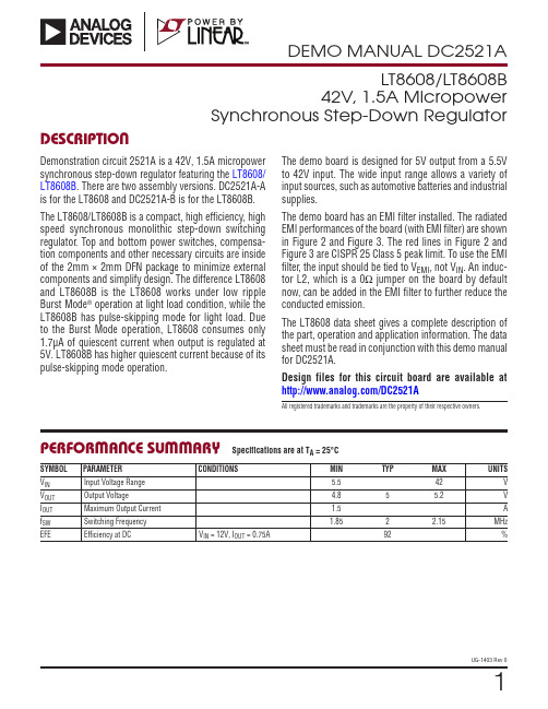
1UG-1403 Rev 0DESCRIPTIONLT8608/LT8608B42V, 1.5A MicropowerSynchronous Step-Down RegulatorDemonstration circuit 2521A is a 42V, 1.5A micropower synchronous step-down regulator featuring the LT8608/LT8608B . There are two assembly versions. DC2521A-A is for the LT8608 and DC2521A-B is for the LT8608B. The LT8608/LT8608B is a compact, high efficiency, high speed synchronous monolithic step-down switching regulator . Top and bottom power switches, compensa-tion components and other necessary circuits are inside of the 2mm × 2mm DFN package to minimize external components and simplify design. The difference LT8608 and LT8608B is the LT8608 works under low ripple Burst Mode ® operation at light load condition, while the LT8608B has pulse-skipping mode for light load. Due to the Burst Mode operation, LT8608 consumes only 1.7μA of quiescent current when output is regulated at 5V. LT8608B has higher quiescent current because of its pulse-skipping mode operation.All registered trademarks and trademarks are the property of their respective owners.PERFORMANCE SUMMARYThe demo board is designed for 5V output from a 5.5V to 42V input. The wide input range allows a variety of input sources, such as automotive batteries and industrial supplies.The demo board has an EMI filter installed. The radiated EMI performances of the board (with EMI filter) are shown in Figure 2 and Figure 3. The red lines in Figure 2 and Figure 3 are CISPR 25 Class 5 peak limit. To use the EMI filter , the input should be tied to V EMI , not V IN . An induc-tor L2, which is a 0Ω jumper on the board by default now, can be added in the EMI filter to further reduce the conducted emission.The LT8608 data sheet gives a complete description of the part, operation and application information. The data sheet must be read in conjunction with this demo manual for DC2521A.Design files for this circuit board are available at /DC2521ASpecifications are at T A = 25°CSYMBOL PARAMETER CONDITIONSMIN TYPMAX UNITSV IN Input Voltage Range 5.542V V OUT Output Voltage4.855.2V I OUT Maximum Output Current 1.5A f SW Switching Frequency 1.852 2.15MHz EFEEfficiency at DCV IN = 12V, I OUT = 0.75A92%2UG-1403 Rev 0QUICK START PROCEDUREDC2521A is easy to set up to evaluate the performance of the LT8608/LT8608B. Refer to Figure 4 for proper measurement equipment setup and follow the proce-dure below:NOTE: When measuring the input or output voltage ripple, care must be taken to avoid a long ground lead on the oscilloscope probe. See Figure 5 for the proper scope technique. 1. Set an input power supply that is capable of 42V/1.5A. Then turn off the supply.2. With power off, connect the supply to the input termi-nals V IN and GND.3. Turn on the power at the input.NOTE: Make sure that the input voltage never exceeds 42V.4. Check for the proper output voltage of 5V. Turn off the power at the input.5. Once the proper output voltage is established, connect a variable load capable of sinking 1.5A at 5V to the output terminals V OUT and GND. Set the current for 0A.a. If efficiency measurements are desired, an amme-ter can be put in series with the output load in order to measure the DC2521A’s output current.b. A voltmeter can be placed across the output ter-minals in order to get an accurate output voltage measurement.6. Turn on the power at the input.NOTE: If there is no output, temporarily disconnect the load to make sure that the load is not set too high.7. Once the proper output voltage is established again,adjust the load and/or input within the operating range and observe the output voltage regulation, ripple volt-age, efficiency and other desired parameters.Figure 2. LT8608/LT8608B Demo Circuit EMI Performance in CISPR 25 Radiated Emission Test, Antenna Polarization: Vertical (V IN = 14V, V OUT = 5V, I OUT= 1.5A, 2MHz Switching Frequency)Figure 1. Efficiency vs Load Current at 12V Input and 2MHz Switching FrequencyFigure 3. LT8608/LT8608B Demo Circuit EMI Performance inCISPR 25 Radiated Emission Test, Antenna Polarization: Horizontal (V IN = 14V, V OUT = 5V, I OUT = 1.5A, 2MHz Switching Frequency)QUICK START PROCEDUREFigure 4. Proper Measurement Equipment SetupFigure 5. Measuring Output RippleOUT3UG-1403 Rev 0PARTS LISTITEM QTY REFERENCE PART DESCRIPTION MANUFACTURER/PART NUMBERRequired Circuit Components11C2CAP., X7R, 4.7μF, 50V, 10% 1206MURATA, GRM31CR71H475K21C4CAP., X7R, 0.22μF, 16V, 10%, 0603AVX, 0603YC224KAT2A31C5CAP., C0G, 10pF, 25V, 5%, 0603AVX, 06033A100JAT2A41C6CAP., X7R, 47μF, 10V, 10%, 1210MURATA, GRM32ER71A476KE20L51C7CAP., X7R, 1.0μF, 25V, 10%, 0603MURATA, GRM188R71E105KA12D61L1 IND., 2.2µH WURTH ELEKTRONIK, 7443833602271R2RES., CHIP, 18.2k, 1/10W, 1%, 0603VISHAY, CRCW060318K2FKEA81R3 RES., CHIP, 49.9k, 1/10W, 1%, 0603VISHAY, CRCW060349K9FKEA92R1, R4RES., CHIP, 1MEG, 1/10W, 1%, 0603VISHAY, CRCW06031M00FKEA101R5RES., CHIP, 187k, 1/10W, 1%, 0603VISHAY, CRCW0603187KFKEADC2521A-A Version Specific Components11U1IC, REGULATOR, DFN-8ANALOG DEVICES, LT8608EDC#PBFDC2521A-B Version Specific Components11U1IC, REGULATOR, DFN-8ANALOG DEVICES, LT8608BEDC#PBF Additional Demo Board Circuit Components11C1CAP., ALUM 22μF 63V SUN ELECT, 63CE22BS22C3, C10CAP., X7R, 4.7μF, 50V, 10% 1206MURATA, GRM31CR71H475K31C8CAP., X7R, 1μF, 50V, 10%, 0805TDK, C2012X7R1H105K41C9CAP., X7R, 4.7μF, 16V, 10%, 0805MURATA, GRM21BR71C475K73L52C11, C12CAP., X7R, 0.1μF, 50V, 10%, 0603MURATA, GRM188R71H104KA93D61FB1FERRITE BEAD 0805TDK, MPZ2012S221AT00071L2RES., CHIP, 0Ω, 3/4W, 2010VISHAY, CRCW20100000Z0EF80R6 (OPT.)RES., 0603Hardware For Demo Board Only17E1 − E7TESTPOINT, TURRET, 0.094"MILL-MAX, 2501-2-00-80-00-00-07-021E8 (OPT.)TESTPOINT, TURRET, 0.094"34MH1 − MH4STAND-OFF, NYLON 0.50 TALL KEYSTONE, 8833 (SNAP ON)4UG-1403 Rev 05UG-1403 Rev 0Information furnished by Analog Devices is believed to be accurate and reliable. However , no responsibility is assumed by Analog Devices for its use, nor for any infringements of patents or other rights of third parties that may result from its use. Specifications subject to change without notice. No license is granted by implication or otherwise under any patent or patent rights of Analog Devices.SCHEMATIC DIAGRAM6UG-1403 Rev 0ANALOG DEVICES, INC. 2018UG17098-0-7/18(0)ESD CautionESD (electrostatic discharge) sensitive device. Charged devices and circuit boards can discharge without detection. Although this product features patented or proprietary protection circuitry, damage may occur on devices subjected to high energy ESD. Therefore, proper ESD precautions should be taken to avoid performance degradation or loss of functionality.Legal Terms and ConditionsBy using the evaluation board discussed herein (together with any tools, components documentation or support materials, the “Evaluation Board”), you are agreeing to be bound by the terms and conditions set forth below (“Agreement”) unless you have purchased the Evaluation Board, in which case the Analog Devices Standard Terms and Conditions of Sale shall govern. Do not use the Evaluation Board until you have read and agreed to the Agreement. Your use of the Evaluation Board shall signify your acceptance of the Agreement. This Agreement is made by and between you (“Customer”) and Analog Devices, Inc. (“ADI”), with its principal place of business at One Technology Way, Norwood, MA 02062, USA. Subject to the terms and conditions of the Agreement, ADI hereby grants to Customer a free, limited, personal, temporary, non-exclusive, non-sublicensable, non-transferable license to use the Evaluation Board FOR EVALUATION PURPOSES ONL Y. Customer understands and agrees that the Evaluation Board is provided for the sole and exclusive purpose referenced above, and agrees not to use the Evaluation Board for any other purpose. Furthermore, the license granted is expressly made subject to the following additional limitations: Customer shall not (i) rent, lease, display, sell, transfer , assign, sublicense, or distribute the Evaluation Board; and (ii) permit any Third Party to access the Evaluation Board. As used herein, the term “Third Party” includes any entity other than ADI, Customer , their employees, affiliates and in-house consultants. The Evaluation Board is NOT sold to Customer; all rights not expressly granted herein, including ownership of the Evaluation Board, are reserved by ADI. CONFIDENTIALITY. This Agreement and the Evaluation Board shall all be considered the confidential and proprietary information of ADI. Customer may not disclose or transfer any portion of the Evaluation Board to any other party for any reason. Upon discontinuation of use of the Evaluation Board or termination of this Agreement, Customer agrees to promptly return the Evaluation Board to ADI. ADDITIONAL RESTRICTIONS. Customer may not disassemble, decompile or reverse engineer chips on the Evaluation Board. Customer shall inform ADI of any occurred damages or any modifications or alterations it makes to the Evaluation Board, including but not limited to soldering or any other activity that affects the material content of the Evaluation Board. Modifications to the Evaluation Board must comply with applicable law, including but not limited to the RoHS Directive. TERMINATION. ADI may terminate this Agreement at any time upon giving written notice to Customer . Customer agrees to return to ADI the Evaluation Board at that time. LIMITATION OF LIABILITY. THE EVALUATION BOARD PROVIDED HEREUNDER IS PROVIDED “AS IS” AND ADI MAKES NO WARRANTIES OR REPRESENTATIONS OF ANY KIND WITH RESPECT TO IT . ADI SPECIFICALL Y DISCLAIMS ANY REPRESENTATIONS, ENDORSEMENTS, GUARANTEES, OR WARRANTIES, EXPRESS OR IMPLIED, RELATED TO THE EVALUATION BOARD INCLUDING, BUT NOT LIMITED TO, THE IMPLIED WARRANTY OF MERCHANTABILITY, TITLE, FITNESS FOR A PARTICULAR PURPOSE OR NONINFRINGEMENT OF INTELLECTUAL PROPERTY RIGHTS. IN NO EVENT WILL ADI AND ITS LICENSORS BE LIABLE FOR ANY INCIDENTAL, SPECIAL, INDIRECT , OR CONSEQUENTIAL DAMAGES RESUL TING FROM CUSTOMER’S POSSESSION OR USE OF THE EVALUATION BOARD, INCLUDING BUT NOT LIMITED TO LOST PROFITS, DELAY COSTS, LABOR COSTS OR LOSS OF GOODWILL. ADI’S TOTAL LIABILITY FROM ANY AND ALL CAUSES SHALL BE LIMITED TO THE AMOUNT OF ONE HUNDRED US DOLLARS ($100.00). EXPORT . Customer agrees that it will not directly or indirectly export the Evaluation Board to another country, and that it will comply with all applicable United States federal laws and regulations relating to exports. GOVERNING LAW . This Agreement shall be governed by and construed in accordance with the substantive laws of the Commonwealth of Massachusetts (excluding conflict of law rules). Any legal action regarding this Agreement will be heard in the state or federal courts having jurisdiction in Suffolk County, Massachusetts, and Customer hereby submits to the personal jurisdiction and venue of such courts. The United Nations Convention on Contracts for the International Sale of Goods shall not apply to this Agreement and is expressly disclaimed.。
TD信息元素详解
信息元素功能性定义作者:李欣目录目录 (1)信息元素功能性定义 (11)1 核心网信息元素 (11)1.1 CN Information elements (11)1.2 CN Domain System Information (11)1.3 CN Information info (11)1.4 IMEI (11)1.5 IMSI (GSM-MAP) (11)1.6 Intra Domain NAS Node Selector (11)1.7 Location Area Identification (12)1.8 NAS message (12)1.9 NAS system information (GSM-MAP) (12)1.10 Paging record type identifier (12)1.11 PLMN identity (12)1.12 PLMN Type (12)1.13 P-TMSI (GSM-MAP) (12)1.14 RAB identity (12)1.15 Routing Area Code (12)1.16 Routing Area Identification (13)1.17 TMSI (GSM-MAP) (13)2 UTRAN 移动信息元素 (13)2.1 Cell Access Restriction (13)2.2 Cell identity (13)2.3 Cell selection and re-selection info for SIB3/4 (13)2.4 Cell selection and re-selection info for SIB11/12 (13)2.5 Mapping Info (14)2.6 URA identity (14)3 UE 信息元素 (14)3.1 Activation time (14)3.2 Capability Update Requirement (14)3.3 Cell update cause (15)3.4 Ciphering Algorithm (15)3.5 Ciphering mode info (15)3.6 CN domain specific DRX cycle length coefficient (15)3.7 CPCH Parameters (15)3.8 C-RNTI (15)3.9 DRAC system information (15)3.10 Void (16)3.11 Establishment cause (16)3.12 Expiration Time Factor (16)3.13 Failure cause (16)3.14 Failure cause and error information (16)3.15 Initial UE identity (16)3.16 Integrity check info (16)3.17 Integrity protection activation info (17)3.18 Integrity protection Algorithm (17)3.19 Integrity protection mode info (17)3.20 Maximum bit rate (17)3.21 Measurement capability (17)3.22 Paging cause (17)3.23 Paging record (17)3.24 PDCP capability (17)3.25 Physical channel capability (18)3.26 Protocol error cause (18)3.27 Protocol error indicator (18)3.28 RB timer indicator (18)3.29 Redirection info (18)3.30 Re-establishment timer (18)3.31 Rejection cause (18)3.32 Release cause (18)3.33 RF capability FDD (19)3.34 RLC capability (19)3.35 RLC re-establish indicator (19)3.36 RRC transaction identifier (19)3.37 Security capability (19)3.38 START (19)3.39 Transmission probability (19)3.40 Transport channel capability (20)3.41 UE multi-mode/multi-RAT capability (20)3.42 UE radio access capability (20)3.43 UE Timers and Constants in connected mode (21)3.44 UE Timers and Constants in idle mode (21)3.45 UE positioning capability (21)3.46 URA update cause (21)3.47 U-RNTI (21)3.48 U-RNTI Short (21)3.49 UTRAN DRX cycle length coefficient (21)3.50 Wait time (21)3.51 UE Specific Behavior Information 1 idle (21)3.52 UE Specific Behavior Information 1 interRAT (22)4 无线承载信息元素 (22)4.0 Default configuration identity (22)4.1 Downlink RLC STATUS info (22)4.2 PDCP info (22)4.3 PDCP SN info (22)4.4 Polling info (22)4.5 Predefined configuration identity (23)4.6 Predefined configuration value tag (23)4.7 Predefined RB configuration (23)4.8 RAB info (23)4.9 RAB info Post (23)4.10 RAB information for setup (23)4.11 RAB information to reconfigure (24)4.12 NAS Synchronization indicator (24)4.13 RB activation time info (24)4.14 RB COUNT-C MSB information (24)4.15 RB COUNT-C information (24)4.16 RB identity (24)4.17 RB information to be affected (24)4.18 RB information to reconfigure (25)4.19 RB information to release (25)4.20 RB information to setup (25)4.21 RB mapping info (25)4.22 RB with PDCP information (25)4.23 RLC info (25)4.24 Signaling RB information to setup (26)4.25 Transmission RLC Discard (26)5 传输信道信息元素 (26)5.1 Added or Reconfigured DL TrCH information (26)5.2 Added or Reconfigured UL TrCH information (27)5.3 CPCH set ID (27)5.4 Deleted DL TrCH information (27)5.5 Deleted UL TrCH information (27)5.6 DL Transport channel information common for all transport channels (27)5.7 DRAC Static Information (27)5.8 Power Offset Information (28)5.9 Predefined TrCH configuration (28)5.10 Quality Target (28)5.11 Semi-static Transport Format Information (28)5.12 TFCI Field 2 Information (28)5.13 TFCS Explicit Configuration (28)5.14 TFCS Information for DSCH (TFCI range method) (29)5.15 TFCS Reconfiguration/Addition Information (29)5.16 TFCS Removal Information (29)5.17 Void (29)5.18 Transport channel identity (29)5.19 Transport Format Combination (TFC) (29)5.20 Transport Format Combination Set (29)5.21 Transport Format Combination Set Identity (29)5.22 Transport Format Combination Subset (29)5.23 Transport Format Set (29)5.24 UL Transport channel information common for all transport channels (30)6 物理信道信息元素 (30)6.1 AC-to-ASC mapping (30)6.2 AICH Info (30)6.3 AICH Power offset (30)6.4 Allocation period info (30)6.5 Alpha (30)6.6 ASC Setting (30)6.7 Void (31)6.8 CCTrCH power control info (31)6.9 Cell parameters Id (31)6.10 Common timeslot info (31)6.11 Constant value (31)6.12 CPCH persistence levels (31)6.13 CPCH set info (31)6.14 CPCH Status Indication mode (31)6.15 CSICH Power offset (32)6.16 Default DPCH Offset Value (32)6.17 Downlink channelisation codes (32)6.18 Downlink DPCH info common for all RL (32)6.19 Downlink DPCH info common for all RL Post (32)6.20 Downlink DPCH info common for all RL Pre (32)6.21 Downlink DPCH info for each RL (32)6.22 Downlink DPCH info for each RL Post (33)6.23 Downlink DPCH power control information (33)6.24 Downlink information common for all radio links (33)6.25 Downlink information common for all radio links Post (33)6.26 Downlink information common for all radio links Pre (33)6.27 Downlink information for each radio link (33)6.28 Downlink information for each radio link Post (33)6.29 Void (33)6.30 Downlink PDSCH information (33)6.31 Downlink rate matching restriction information (34)6.32 Downlink Timeslots and Codes (34)6.33 DPCH compressed mode info (34)6.34 DPCH Compressed Mode Status Info (34)6.35 Dynamic persistence level (34)6.36 Frequency info (34)6.37 Individual timeslot info (35)6.38 Individual Timeslot interference (35)6.39 Maximum allowed UL TX power (35)6.40 Void (35)6.41 Midamble shift and burst type (35)6.42 PDSCH Capacity Allocation info (35)6.43 PDSCH code mapping (36)6.44 PDSCH info (36)6.45 PDSCH Power Control info (36)6.46 PDSCH system information (36)6.47 PDSCH with SHO DCH Info (36)6.48 Persistence scaling factors (36)6.49 PICH Info (36)6.50 PICH Power offset (37)6.51 PRACH Channelisation Code List (37)6.52 PRACH info (for RACH) (37)6.53 PRACH partitioning (37)6.54 PRACH power offset (37)6.55 PRACH system information list (37)6.56 Predefined PhyCH configuration (38)6.57 Primary CCPCH info (38)6.58 Primary CCPCH info post (38)6.59 Primary CCPCH TX Power (38)6.60 Primary CPICH info (38)6.61 Primary CPICH Tx power (38)6.62 Primary CPICH usage for channel estimation (38)6.63 PUSCH info (38)6.64 PUSCH Capacity Allocation info (38)6.65 PUSCH power control info (39)6.66 PUSCH system information (39)6.67 RACH transmission parameters (39)6.68 Radio link addition information (39)6.69 Radio link removal information (39)6.70 SCCPCH Information for FACH (39)6.71 Secondary CCPCH info (39)6.72 Secondary CCPCH system information (40)6.73 Secondary CPICH info (40)6.74 Secondary scrambling code (40)6.75 SFN Time info (40)6.76 SSDT cell identity (40)6.77 SSDT information (40)6.78 STTD indicator (40)6.79 TDD open loop power control (41)6.80 TFC Control duration (41)6.81 TFCI Combining Indicator (41)6.82 TGPSI (41)6.83 Time info (41)6.84 Timeslot number (41)6.85 TPC combination index (41)6.86 TSTD indicator (41)6.87 TX Diversity Mode (41)6.88 Uplink DPCH info (41)6.89 Uplink DPCH info Post (42)6.90 Uplink DPCH info Pre (42)6.91 Uplink DPCH power control info (42)6.92 Uplink DPCH power control info Post (42)6.93 Uplink DPCH power control info Pre (42)6.94 Uplink Timeslots and Codes (42)6.95 Uplink Timing Advance (42)6.96 Uplink Timing Advance Control (43)7 测量信息元素 (43)7.1 Additional measurements list (43)7.2 Cell info (43)7.3 Cell measured results (43)7.4 Cell measurement event results (44)7.5 Cell reporting quantities (44)7.6 Cell synchronization information (44)7.7 Event results (44)7.8 FACH measurement occasion info (45)7.9 Filter coefficient (45)7.10 HCS Cell re-selection information (45)7.11 HCS neighboring cell information (45)7.12 HCS Serving cell information (45)7.13 Inter-frequency cell info list (46)7.14 Inter-frequency event identity (46)7.15 Inter-frequency measured results list (46)7.16 Inter-frequency measurement (46)7.17 Inter-frequency measurement event results (47)7.18 Inter-frequency measurement quantity (47)7.19 Inter-frequency measurement reporting criteria (47)7.20 Inter-frequency measurement system information (47)7.21 Inter-frequency reporting quantity (47)7.22 Inter-frequency SET UPDATE (48)7.23 Inter-RAT cell info list (48)7.24 Inter-RAT event identity (48)7.25 Inter-RAT info (48)7.26 Inter-RAT measured results list (48)7.27 Inter-RAT measurement (49)7.28 Inter-RAT measurement event results (49)7.29 Inter-RAT measurement quantity (49)7.30 Inter-RAT measurement reporting criteria (49)7.31 Inter-RAT measurement system information (50)7.32 Inter-RAT reporting quantity (50)7.33 Intra-frequency cell info list (50)7.34 Intra-frequency event identity (50)7.35 Intra-frequency measured results list (50)7.36 Intra-frequency measurement (50)7.37 Intra-frequency measurement event results (51)7.38 Intra-frequency measurement quantity (51)7.39 Intra-frequency measurement reporting criteria (51)7.40 Intra-frequency measurement system information (51)7.41 Intra-frequency reporting quantity (52)7.42 Intra-frequency reporting quantity for RACH reporting (52)7.43 Maximum number of reported cells on RACH (52)7.44 Measured results (52)7.45 Measured results on RACH (52)7.46 Measurement Command (52)7.47 Measurement control system information (53)7.48 Measurement Identity (53)7.49 Measurement reporting mode (53)7.50 Measurement Type (53)7.51 Measurement validity (53)7.52 Observed time difference to GSM cell (53)7.53 Periodical reporting criteria (53)7.54 Primary CCPCH RSCP info (54)7.55 Quality measured results list (54)7.56 Quality measurement (54)7.57 Quality measurement event results (54)7.58 Quality measurement reporting criteria (54)7.59 Quality reporting quantity (54)7.60 Reference time difference to cell (54)7.61 Reporting Cell Status (55)7.62 Reporting information for state CELL_DCH (55)7.63 SFN-SFN observed time difference (55)7.64 Time to trigger (55)7.65 Timeslot ISCP info (55)7.66 Traffic volume event identity (55)7.67 Traffic volume measured results list (55)7.68 Traffic volume measurement (55)7.69 Traffic volume measurement event results (56)7.70 Traffic volume measurement object (56)7.71 Traffic volume measurement quantity (56)7.72 Traffic volume measurement reporting criteria (56)7.73 Traffic volume measurement system information (56)7.74 Traffic volume reporting quantity (56)7.75 UE internal event identity (56)7.76 UE internal measured results (57)7.77 UE internal measurement (57)7.78 UE internal measurement event results (57)7.79 UE internal measurement quantity (57)7.80 UE internal measurement reporting criteria (57)7.81 Void (58)7.82 UE Internal reporting quantity (58)7.83 UE Rx-Tx time difference type 1 (58)7.84 UE Rx-Tx time difference type 2 (58)7.85 UE Transmitted Power info (58)7.86 UE positioning Ciphering info (58)7.87 UE positioning Error (58)7.88 UE positioning GPS acquisition assistance (59)7.89 UE positioning GPS almanac (59)7.90 UE positioning GPS assistance data (59)7.91 UE positioning GPS DGPS corrections (59)7.92 UE positioning GPS ionospheric model (59)7.93 UE positioning GPS measured results (59)7.94 UE positioning GPS navigation model (60)7.95 UE positioning GPS real-time integrity (60)7.96 UE positioning GPS reference time (60)7.97 UE positioning GPS UTC model (61)7.98 UE positioning IPDL parameters (61)7.99 UE positioning measured results (61)7.100 UE positioning measurement (61)7.101 UE positioning measurement event results (61)7.102 Void (62)7.103 UE positioning OTDOA assistance data for UE-assisted (62)7.104 Void (62)7.105 UE positioning OTDOA measured results (62)7.106 UE positioning OTDOA neighbor cell info (62)7.107 UE positioning OTDOA quality (63)7.108 UE positioning OTDOA reference cell info (63)7.109 UE positioning position estimate info (64)7.110 UE positioning reporting criteria (64)7.111 UE positioning reporting quantity (64)7.112 T ADV info (65)8 其它信息元素 (65)8.1 BCCH modification info (65)8.2 BSIC (65)8.3 CBS DRX Level 1 information (65)8.4 Cell Value tag (65)8.5 Inter-RAT change failure (65)8.6 Inter-RAT handover failure (66)8.7 Inter-RAT UE radio access capability (66)8.8 Void (66)8.9 MIB Value tag (66)8.10 PLMN Value tag (66)8.11 Predefined configuration identity and value tag (66)8.12 Protocol error information (66)8.13 References to other system information blocks (66)8.14 References to other system information blocks and scheduling blocks (67)8.15 Rplmn information (67)8.16 Scheduling information (67)8.17 SEG COUNT (67)8.18 Segment index (67)8.19 SIB data fixed (67)8.20 SIB data variable (67)8.21 SIB type (67)8.22 SIB type SIBs only (67)9 ANSI-41 Information elements (68)10 Multiplicity values and type constraint values (68)信息元素功能性定义消息是由多个信息元素组合而成,信息元素根据其功能的不同划分为:核心网域信息元素、UTRAN 移动信息元素、UE 信息元素、无线承载信息元素、传输信道信息元素、物理信道信息元素和测量信息元素。
IBM Cognos Transformer V11.0 用户指南说明书
teb参数inflation_dist接近小车半径 -回复

teb参数inflation_dist接近小车半径-回复问题“[teb参数inflation_dist接近小车半径]”是指在路径规划算法中,使用TEB(time-optimal educational trajectory planner)算法时,设定的路径膨胀参数(inflation_dist)与小车的半径接近的情况。
本文将逐步回答以下问题:什么是路径膨胀、TEB算法和路径膨胀参数inflation_dist,为什么将inflation_dist接近小车半径,并讨论这种设置可能带来的影响。
第一节:路径膨胀的定义与作用(字数:350 字)路径膨胀是一种路径规划算法中常用的技术,用于将机器或车辆的膨胀边界考虑在内,以避免可能的碰撞或接触。
当规划一条路径时,路径周围的空间被一层层进行膨胀,以确保在路径上不会有与障碍物的碰撞。
路径膨胀的大小通常由路径膨胀参数来确定。
第二节:TEB算法概述(字数:350 字)TEB(time-optimal educational trajectory planner)算法是一种被广泛应用的时间最优教育轨迹规划算法。
它通过在车辆行进的过程中考虑加速度和速度的限制,以最小化规划路径的运行时间。
TEB算法能够充分利用车辆的机械特性,使得路径规划更加高效准确。
第三节:路径膨胀参数inflation_dist解释(字数:350 字)路径膨胀参数inflation_dist是指在TEB算法中,将该参数设置为一个与小车半径接近的值。
该参数表示路径膨胀的范围,即将路径膨胀到周围空间的距离。
当inflation_dist接近小车半径时,路径规划算法会更加关注车辆的侧向空间,以避免与障碍物的接触或碰撞。
第四节:将inflation_dist设置接近小车半径的原因(字数:350 字)将inflation_dist设置接近小车半径有以下原因。
首先,这样可以增加路径规划算法对车辆周围的侧向空间的关注,避免了车辆可能与障碍物接触的风险。
n_predict 参数

n_predict 参数English answer:The `n_predict` parameter is used to specify the number of future time steps to predict. By default, it is set to 1, which means that the model will only predict the next time step. However, you can increase this value to predict multiple future time steps.For example, if you have a time series of daily temperatures and you want to predict the temperature forthe next 7 days, you would set the `n_predict` parameter to 7. This would tell the model to predict the temperature for the next 7 days, based on the historical data that you have provided.It is important to note that the accuracy of the predictions will decrease as the number of future timesteps increases. This is because the model is less certain about the future the further out it tries to predict.Therefore, you should only set the `n_predict` parameter to a value that is necessary for your application. If you are only interested in predicting the next few time steps, then you can set the parameter to a low value. However, if you need to predict a longer range of future time steps, then you can set the parameter to a higher value.Here are some examples of how the `n_predict` parameter can be used:To predict the next time step in a time series, set`n_predict` to 1.To predict the next 7 days in a time series, set`n_predict` to 7.To predict the next month in a time series, set`n_predict` to 30.To predict the next year in a time series, set`n_predict` to 365.The `n_predict` parameter is a powerful tool that can be used to make predictions about future time steps. By understanding how to use this parameter, you can get the most out of your time series models.中文回答:n_predict 参数用于指定要预测的未来时间步长数。
model_predictive_path_integral的讲解_概述说明

model predictive path integral的讲解概述说明1. 引言1.1 概述本文将介绍Model Predictive Path Integral (MPPI)的讲解,该方法是一种用于路径规划和控制的优化技术。
它通过在机器人、飞行器或自动驾驶车辆等系统中进行模型预测,并使用路径积分来生成最佳轨迹。
MPPI算法的核心思想是综合考虑短期和长期目标,在保证系统性能和鲁棒性的同时,尽可能优化路径。
1.2 文章结构本文主要分为五个部分。
首先,在引言部分提供MPPI方法的概述,并介绍文章结构。
接下来,第二部分将详细解释MPPI的原理,并描述算法步骤。
第三部分将阐述MPPI在不同领域的应用,包括机器人运动规划、飞行器轨迹控制以及自动驾驶车辆路径生成。
然后,在第四部分将对MPPI的优点和缺点进行全面分析。
最后,在结论与展望部分总结文章所介绍的内容,并提出未来研究方向。
1.3 目的通过这篇文章,旨在为读者提供一个清晰而详细的理解Model Predictive Path Integral (MPPI)方法,并认识到它在路径规划和控制问题中的实际应用。
读者将理解MPPI算法的原理、步骤以及其在机器人、飞行器和自动驾驶车辆等领域的优点和缺点。
同时,文章还将探讨MPPI方法的未来发展方向,为后续研究提供有益的指导。
2. Model Predictive Path Integral (MPPI)2.1 简介Model Predictive Path Integral (MPPI)是一种基于路径积分的预测模型控制方法,被广泛应用于机器人运动规划、飞行器轨迹控制和自动驾驶车辆路径生成等领域。
该方法通过将控制问题转化为优化问题,并使用路径积分来评估不同控制策略的性能,从而找到最佳的控制策略来实现所需任务。
2.2 原理解析MPPI的原理是基于随机采样和近似推理的方法。
首先,它从当前状态开始,使用采样函数生成多个随机样本,并根据这些样本计算每个可能的轨迹的性能(代价函数)。
bert训练中10%token随机替换的作用

在BERT(Bidirectional Encoder Representations from Transformers)训练过程中,随机替换10%的token是一种常见的正则化技术,被称为“Masked Language Modeling”(Masked LM)或“Next-Sentence Prediction”(NSP)。
这种做法有以下目的和作用:
1.正则化:通过随机替换部分输入token,增加了训练的多样性和模型的健
壮性。
这有助于防止模型过拟合,使得模型在未见过的数据分布上表现更好。
2.上下文理解:由于BERT使用Transformer的双向性,它能够同时理解一
个词的前后上下文。
通过遮蔽某些token,模型需要在不考虑这些token 的情况下预测或补全句子,这有助于它更好地理解和表示文本的上下文信息。
3.掩码预测:在训练过程中,模型需要预测被随机替换的token是什么。
这
不仅有助于提高模型的泛化能力,还使得模型能够学习到更丰富的语言表示。
4.句子关系理解:通过判断两个连续的句子是否相关(NSP任务),模型能
够学习到句子之间的逻辑和语义关系。
这对于许多NLP任务(如问答、摘要生成等)是有益的。
5.模型效果评估:使用掩码语言模型或其他相关任务可以对模型进行评估和
验证,确保模型在训练和测试数据上的表现是一致的。
这种随机替换的方法有助于提高BERT模型的泛化能力、上下文理解能力和句子关系理解能力,是BERT训练中不可或缺的一部分。
在使用BERT中的一些参数记录

在使用BERT中的一些参数记录BERT(Bidirectional Encoder Representations from Transformers)是一种先进的预训练语言模型,应用广泛于自然语言处理领域。
在使用BERT时,有一些重要的参数需要记录和理解。
以下是关于BERT中一些重要参数的记录。
1. 预训练任务(Pretraining Task):BERT使用了两种预训练任务,即Masked Language Model(MLM)和Next Sentence Prediction(NSP)。
- MLM任务:在输入的句子中,随机mask一些词,并让模型预测被mask的词。
-NSP任务:给定两个句子,模型需要判断这两个句子是否是相邻的。
2. 输入表示(Input Representations):BERT使用了WordPiece嵌入方式,将句子拆解成多个子词作为输入。
每个子词(包括单个字符)都有一个对应的特殊标记,并用于构建输入表示。
3. 分割标记(Segment Embeddings):为了表示输入文本中的不同句子,BERT引入了分割标记。
在输入序列中,两个句子分别用[SEP]标记分隔,并为每个词嵌入一个句子标识符。
4. 注意力掩码(Attention Mask):BERT输入序列中的每个词都被分配了一个注意力掩码,用来指示这个词是否是有效输入。
掩码为1的位置是有效的词,而掩码为0的位置则是填充或无效的位置。
5. Transformer层(Transformer Layers):BERT模型由多个Transformer层组成。
每个Transformer层由多头自注意力机制(Multi-Head Self-Attention)和前馈神经网络(Feed-Forward Neural Network)组成。
6. 隐藏状态(Hidden States):BERT输出的隐藏状态是每个输入词的表示。
BERT的隐藏状态可以用于许多下游任务,如文本分类、命名实体识别等。
convert model to traced-model的作用

convert model to traced-model的作用
在深度学习中,将模型转换为"traced-model"通常指的是将模型转换为一种更轻量化的形式,以便更容易在不同的平台上部署和运行。
这通常涉及将模型的权重和结构保存为一种可移植的格式,例如TorchScript。
下面是一些关于将模型转换为traced-model的一些常见目的和优势:
1. 部署和推理效率:
- Traced model通常比原始模型更轻量,可以更容易地在边缘设备、移动设备或嵌入式系统上进行部署。
这对于实时推理和资源受限的环境非常有用。
2. 跨平台兼容性:
- Traced model的表示形式通常是平台无关的,可以更容易地在不同的深度学习框架或平台之间转换。
这使得模型更具灵活性,可以在不同的生态系统中使用。
3. 模型序列化和反序列化:
-将模型转换为traced model使得模型可以轻松地序列化和反序列化。
这对于在不同系统之间传输、保存和加载模型非常有用。
4. 加速推理:
-在一些情况下,通过将模型转换为traced model,可以实现更高效的推理。
例如,在一些深度学习框架中,traced model可以进行一些静态优化,提高推理速度。
5. 隐藏模型细节:
- Traced model通常会隐藏原始模型的一些细节,使得模型的实现更加简洁和高效。
这有助于保护模型的知识产权和减小模型文件的大小。
总体来说,将模型转换为traced model的主要目标是提高模型的部署和运行效率,使其更适用于实际应用场景。
这一过程通常要取决于使用的深度学习框架和具体的部署需求。
bert的predict代码

bert的predict代码在自然语言处理领域,BERT(Bidirectional Encoder Representations from Transformers)是一种基于Transformer架构的预训练模型,因其在多项任务上的出色表现而备受瞩目。
为了使用BERT进行文本分类、命名实体识别等任务,需要编写相应的predict代码。
本文将详细介绍如何编写BERT的predict代码。
首先,我们需要导入相关的库和模型文件。
在Python中,可以使用Hugging Face提供的transformers库来加载BERT模型,并使用torch库来进行预测。
代码如下所示:```pythonimport torchfrom transformers import BertTokenizer, BertForSequenceClassification# 加载BERT模型和tokenizertokenizer = BertTokenizer.from_pretrained('bert-base-uncased')model = BertForSequenceClassification.from_pretrained('bert-base-uncased', num_labels=2)# 加载已经训练好的模型权重model.load_state_dict(torch.load('model_weights.pth'))# 设置GPU/CPU设备device = torch.device('cuda' if torch.cuda.is_available() else 'cpu')model.to(device)```接下来,我们需要编写一个函数来进行文本预测。
在该函数中,我们需要将输入的文本转换为模型可接受的输入格式,并将其放入模型中进行预测。
NVHD路载荷定义

N VHD路载荷定义2••••定义模型状态定义工况RealizeConnections Create JobAnalysis Manager定义模型状态•在Edit Modules & Connections界面下:•在Modules的Rep列选择表征模型M aster/CMS/LP…•在Modules的State列选择模型状态(MPC/NSM/SPC)•在Connections的State界面选择Connector的State•Step1.在Edit Solution Defination 界面下进行工况设定。
•Step2.Solution type 中选择Frequency Response Analysis•Step3.在弹出的界面中,将loadcase type 切换为Standard•Step4.在弹出的界面中,进一步将Loadcase Type 切换为Road LoadsAnalysis Manager进入Road load utilityAnalysis ManagerRoad Loads•在Road Loads界面下完成:•路谱计算及管理•计算车速选择•加载点管理•工况定义Step1. 激励类型选择Measured Road Surface(默认选项)Step2. 选择原始路面数据存放位置,以及作为路谱计算数据的存储路径,没有指定路径的情况下,下拉菜单为空。
推荐保存在一个固定的路径,而非临时路径。
路径指定方法如下:a. 在主界面顶层菜单栏中找到Preferences,点击在下拉菜单中找到NVH Preferences,点击。
b. 在弹出的界面中,切换至Standard Loadcese, Application type : 选择Road Loads点击Custom folder 后面的+号在下面的文本框中点击文件夹图标选择路面数据的存储路径点击okc.完成后,返回Road Load主界面,此时在select database location 下拉框中存在指定路径。
