Dana 车桥服务手册
现代7E系列柴油叉车产品手册说明书

HYUNDAI MATERIAL HANDLING Applied Tier 3 Engine110/130/160D-7E 2020. 07 Rev.12Some of the photos may include optional equipment.Head Office (Sales office)First tower, 55, Bundang-ro, Bundang-gu, Seongnam-si, Gyeonggi-do, Korea MOVING YOU FURTHERof Big Forklift Truck NEW criterionHyundai introduces a new line of7E-series diesel forklift trucks.Excellent power and performance makesyour business more profitable.Some of the photos may include optional equipment.ESL(Engine Start Limit) Rear View CameraWeight IndicatorCruise Control Instrument SwitchPanelAir Conditioner &High PowerLow Noise15。
Faster Travel Speed& Better GradabilityTravel Speed (Unloaded)The powerful high-output engineprovides greater acceleration, bettergradability and faster travel speed onany tough terrains or slopes.Some of the photos may include optional equipment.110D-7E : 33.3km/h 130D-7E : 33.2km/h160D-7E : 30.9km/h1280 mm 40°Switch Panel Remote Control(Optional)Operating Control LeversOnly minimal operator’s effort isrequired for precise, safe andproductive control.(3-Lever : standard / 4·5-Lever : option)Steering handle is adjustable depending on the operator’s body shape.Adjustability of steering column makes you more comfortable. Positioned PedalsBased on human engineering ; theaccelerator, brake and inching pedalsare optimally positioned for theoperator's convenience.Some of the photos may include optional equipment.(Optional)The rear view camera makes the operation more easy and convenient. And it supports 4 camera channels.(Optional)A load can be placed on the fork and can be accurately weighed by measuring the hydraulic pressure.Lift LockTilt LockDrive LockSome of the photos may include optional equipment.Inspection ReplacementH i g h l y a c c e s s i b l e e n g i n ecompartment allows for quickreplacement of filters.Air cleaner sensor alerts theoperator of a clogged air filter andallows replacement before damage.SpringEngine compartment hood issafely opened by a self locking gasspring.A master switch disconnects thebattery power to protect theelectrical system from excesselectrical drainage.Some of the photos may include optional equipment.Mast SpecificationLoad Capacity110D-7E130D-7E160D-7EOptional Items• FORK (L x W x T)(mm)110D-7E75 x 200 x 1,200 / 75 x 200 x 1,500 / 75 x 200 x 1,800 /75 x 200 x 2,100 / 85 x 200 x 2,440130D-7E85 x 200 x 1,200 / 85 x 200 x 1,500 / 85 x 200 x 1,800 /85 x 200 x 2,100 / 90 x 200 x 2,440160D-7E90 x 200 x 1,200 / 90 x 200 x 1,500 / 95 x 200 x 1,800 /95 x 200 x 2,100 / 95 x 200 x 2,440• MAST :SIMPLEX MAST / TRIPLEX MAST• MCV :4 - SPOOL / 5 - SPOOL• SEAT :NON HEAT / HEAT, Fabric / PVC Leather• BEACON LAMP :AMBER / RED / BLUE• FORK POSITIONER :82 / 100• INTEGRAL SIDE SHIFT + FORK POSITIONER• HYDRAULIC LINE :3 - SPOOL / 4 - SPOOL / 5 - SPOOL• SOLID TIRE• PNEUMATIC TIRE : 18PR LUG (14/16 ONLY)• WIDE CARRIAGE (2,730 mm)• SLIDING TYPE CARRIAGE (160 D-7E)• HEAD GUARD• REAR VIEW CAMERA & WEIGHT INDICATOR• ESL (ENGINE START LIMIT)• HANDS FREE• SEPARATOR HOLDER TYPE CARRIAGE (160D-7E)。
东风德纳6.5吨前桥
东风德纳6.5吨前桥产品使用说明书东风车桥有限公司二○○九年一月重要事项●使用本车桥之前,务必仔细阅读本使用说明书。
●未经我公司许可,擅自拆卸车桥零部件或安装非桥轴系统零部件从而影响桥总成性能的,本公司概不负责。
●为了更好地做好用户的服务工作,车桥要求进行“强制保养”,新出厂车桥在初驶里程1000~2500公里后,必须进行首次保养,首次保养所需注意事项详见“维护与保养”。
此后,用户必须按使用说明书的有关规定做好日常例行维护工作。
前轴模式I字形端面横锻钢梁转向节形式端拳式主销外径Ф52mm制动鼓安装形式轮毂内侧钢板弹簧中心距860mm(可变)主销中心距1870mm(可变)制动器形式气压鼓式制动器,渐开线凸轮配滚轮制动器规格(制动器外径x蹄片宽)Ф400mmx150mm或Ф410mmx180mm项目名义尺寸(mm)维修标准(mm)修理极限(mm)磨损极限(mm)备注主销外径Ф52 ————Ф51.9主销与转向节衬套间间隙——0.01~0.1——0.20主销与前轴孔间的间隙——<0.04——0.15前轮毂起动力——20~65N ————在车轮螺栓处测量转向节起动力——<10N ————在轴头开口销孔处测量转向节与前轴之间的间隙——<0.1 ————垫片调整轮辋的跳动量端面跳动——<1.5 ————径向跳动——<1.5 ————主销内倾角——7º±10′————项目拧紧力矩(N.m)主销的锁销螺母55~70转向节限位螺栓锁止螺母80~100转向上节臂固定螺母280~350横拉杆节臂固定螺母350~450球头销固定螺母250~310横拉杆卡套紧固螺母40~50主销螺塞60~80 防尘盖固定螺母10~20 制动气室紧固螺母55~70 制动气室支架紧固螺母57~78 制动器底板固定螺母160~220 轮毂制动鼓紧固螺母300~420 前调整螺母180~220 轮毂轴承盖调整螺母紧12固螺栓前轴的分解1.气室支架2.密封垫片3.右转向节总成4.螺栓5.右转向节臂6.槽形螺母7.双头螺栓8.直拉杆臂9.槽形螺母10.主销11.上衬套12.调整垫片13.楔形锁销14.止推轴承15.前轴16.螺塞17. 左转向节臂18.转向限位螺钉19.左转向节总成20. 下衬套21.主销堵盖总成22.螺钉23.弯颈滑脂嘴24.油封座圈25.圆柱销26.制动底板27.前轮毂油封28.前轮毂内轴承29.前制动鼓30.螺母31.轮胎螺栓32.前轮毂33.前轮毂外轴承34.减磨挡片35.槽形螺母36.垫密片37.前轮毂盖38.车轮轮辋39.轮辋踏圈40.车轮螺母拆卸要点拆除直拉杆1)拔出开口销。
德纳车桥5.0-13.0 吨后桥总成产品使用说明书

初次换油的里程为 2000km,每行驶24000Km,需再次更换齿轮油。
3
东风德纳车桥有限公司 5.0 ̄13.0 吨后桥总成
选装精磨齿轮、ABS 防抱死刹车装置及刹车自动间隙调整臂装置。 为了帮助用户正确使用和保养车桥,我们编写了这本说明书,本书介绍系
列转向桥的性能特点及使用保养等方面的内容,希望用户使用前认真阅读此使
用说明书,遵守要求的技术保养规程,以确保您的行车安全,提高车桥的使用
寿命。具体的代表桥型如下:
系列编码 DF0501D-305 DF0601D-380 DF0701D-380 DF0801D-385 DF0901D-416
CQH-A-6 mm
维修标准
项目 左、右半轴套管外轴承轴颈径向跳动 半轴中部未加工表面的径向跳动 半轴法兰内端面摆差 轮毂与半轴法兰结合面端面跳动
标准尺寸(mm) —— —— —— ——
使用
拧紧力矩
项
目
半轴法兰盘联接螺栓
制动底板固定螺栓
油平面螺塞
放油螺塞
拆卸半轴
1) 松开半轴螺母。 2) 拆下半轴。如果半轴卸不下,用铜锤 轻轻的敲击半轴法兰,直到半轴松动。
分解轮毂
1) 拆下调整螺母锁片。
2) 卸下调整螺母。 然后依次取下后轮毂外油封、隔套及轴承 注意: 使用轮毂轴承调整螺母扳手来拆卸调整螺母。
3) 拆下轮毂总成。
8
东风德纳车桥有限公司 5.0 ̄13.0 吨后桥总成
头。先顺时针方向转动到拧不动为止,使间隙为零,再反转,听到两声钢珠滑落响为止,此时制动 器摩擦片中部间隙值为 0.4~0.7mm。
东风德纳车桥-质量保修结算管办法20130614
东风德纳车桥有限公司管理标准质量保修结算管理办法 Q/DFDNCQGL1.目的/范围1.1.为规范质量保修索赔结算管理流程,控制不合理索赔支出,使索赔结算管理标准化、程序化,特制定本管理办法。
1.2.本办法适用于东风德纳车桥有限公司(以下简称DDAC)对签约服务站(国内协议站)索赔的受理、索赔凭据审核及索赔结算。
2.定义/术语:质量损失—由于产品质量不符合质量协议(质量协议可以是商务合同的一部分)要求所造成的损失。
它分为直接损失和间接损失。
直接损失—不合格品本身和由其引起的相关产品报废的损失。
间接损失—不合格品从流入需方生产过程中到被发现时为止所造成的连带损失。
即质量损失中除直接损失以外的损失。
质量保修—指产品在供方规定的正确使用前提下,由于产品本身材质、设计、制造缺陷,供方需提供无偿或有条件无偿维修服务。
质量保修期—指供方保证的在一定的里程或时间内对存在质量缺陷的产品承担保修责任的期限,但因设计缺陷严重影响行车安全的项目不受保修期限制,应随时发现随时无条件招回。
质量保修期在双方的商务合同中必须体现和明确。
3.职责市场营销部职责负责督促、监督服务站正确使用DDAC产品。
研发部职责负责售后市场的技术服务援助。
质量部职责负责受理客户的质量抱怨和索赔业务。
财务信息部职责负责服务站申报索赔的结算工作。
4.工作流程4.1.售时索赔4.1.1.DDAC产品在客户入厂检验或装车时发现的质量不良,由客户或DDAC特约服务站及时将信息反馈给DDAC质量部,双方通过沟通确定临时解决方案,包括维修方案。
4.1.2.按双方约定的处置方案,对于属DDAC特约服务站提供的服务(包括材料和工时),由DDAC特约服务站针对每条服务信息逐条填写《质量保修鉴定单》,赔偿单上注明的维修方案必须与双方事前沟通的结果一致。
4.1.3.服务站按时将《质量保修鉴定单》上传DDAC网络质量保修系统,质量部对赔偿单进行审核、确认。
4.1.4.确认完毕后,服务站按双方约定的时间开具索赔增值税发票,并将发票传递至DDAC质量部。
福田戴姆勒行销系统使用说明书(新编)

欧曼行销管理系统Customer Relationship Management用户操作手册(经销商端)User Manual目录系统客户信息操作流程表 (4)系统登录 (5)1信息收集流程管理 (6)1.1录入客户信息(经销商端) (6)1.1.1业务简述 (6)1.1.2启动路径 (6)1.1.3操作细节 (6)1.2客户信息查询(经销商端) (17)1.1.1业务简述 (17)1.1.2启动路径 (17)1.1.3操作细节 (17)1.3计划信息查询(经销商端) (19)1.3.1业务简述 (19)1.3.2启动路径 (19)1.3.3操作细节 (19)2信息分配管理 (20)2.1信息分配(经销商端) (20)2.1.1业务简述 (20)2.1.2启动路径 (20)2.1.3操作细节 (20)3访问流程管理 (23)3.1访问计划制定(经销商端) (23)3.1.1业务简述 (23)3.1.2启动路径 (24)3.1.3操作细节 (24)3.2访问结果录入(经销商端) (28)3.2.1业务简述 (28)3.2.2启动路径 (28)3.2.3操作细节 (28)3.3访问历史查询 (31)3.3.1业务简述 (31)3.3.2启动路径 (31)3.3.3操作细节 (32)4销售促进流程管理 (33)4.1销售促进计划制定(经销商端) (33)4.1.1业务简述 (33)4.1.2启动路径 (33)4.1.3操作细节 (33)4.2销售促进结果录入(经销商端) (37)4.2.1业务简述 (37)4.2.2启动路径 (37)4.2.3操作细节 (37)4.3促进历史查询 (40)4.3.1业务简述 (40)4.3.2启动路径 (40)4.3.3操作细节 (41)5 活动管理 (42)5.1活动策划(经销商端) (42)5.1.1业务简述 (42)5.1.2启动路径 (42)5.1.3操作细节 (42)5.2活动结果录入 (45)5.1.1业务简述 (45)5.1.2启动路径 (45)5.1.3操作细节 (45)5.3活动查询 (47)5.1.1业务简述 (47)5.1.2启动路径 (47)5.1.3操作细节 (47)6 日常业务操作 (49)6.1客户信息完善工作 (49)6.2客户信息平台搭建信息的系统录入 (50)7 疑问解答 (52)7.1信息收集流程管理类 (52)7.2访问流程管理类 (53)7.3信息完善类 (54)7.4客户信息平台搭建类 (54)客户信息操作流程表系统登录1.打开Internet Explorer浏览器,在地址栏中输入/,进入欧曼行销系统登录页面,如下图所示:2.在图中,输入您的用户名和密码,点击“确定”按钮,可以正式进入福田戴姆勒行销系统页面,如下图所示:1信息收集流程管理1.1录入客户信息(经销商端)1.1.1业务简述经销商的销售经理和业务员都可以在系统内添加客户信息,也可以批量添加客户信息,录入完成后,提交到车厂端。
前后桥制动器使用说明书
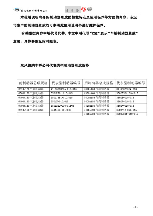
-7-
东风德纳车桥有限公司
制 动
器
后制动器
l、防尘罩 2、螺栓 3、橡胶堵 4、平头销 5、气室支架 6、制动气室 7、凸轮轴 8、垫圈 9、防尘圈
10、垫圈 11、制动调整臂 12、卡环 13、凸轮轴衬套 14、滑脂嘴 15、制动器底板 16、油封 17、滚轮轴 18、滚轮
19、摩擦片铆钉 20、制动摩擦片 21、卡环 22、回位弹簧 23、制动蹄铁 24、蹄片轴 25、制动蹄衬套 26、锁紧螺钉
Ø310x120 气刹制动器 Ø360X130 气刹制动器 Ø400X130 气刹制动器 Ø400X130 气刹制动器 Ø400x150 气刹制动器 Ø410x180 气刹制动器
代表型制动器编号
Q1-3501S23A-010/015 3501RS01-010/015 3501.6B1-010/015 3501N-010/015 3501N12-010/015-B 3501ZB3-001/002
-1-
东风德纳车桥有限公司
制 动
器
技术参数
结 构 型 式
前轴制动器 制动鼓内径(mm) 后桥制动器 制动摩擦片 厚度(mm) 制动器凸轮型式 前轴制动器 AXBXC一数量(基圆) 后桥制动器 制动间隙调整方法 CQZ-B-3 间隙机构调整 前轴制动器 后桥制动器 CQZ-B-1 CQZ-F-2 CQZ-B-2 渐开线 CQZ-F-3 固定销支承的助减势蹄外张式蹄式制动器 CQZ-F-1
东风德纳车桥有限公司
制 动
器
本使用说明书介绍制动器总成的性能特点及使用保养等方面的内容,我公 司生产的制动器总成均可参照此使用说明书进行维护保养。 有关数据内容中用代号代替。 本文中用代号 “CQZ” 表示 “车桥制动器总成” 意思,具体参数见附对照表。
Strongway 大型车轮更换器用户手册说明书
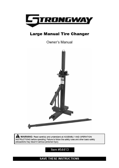
Large Manual Tire ChangerOwner’s ManualWARNING: Read carefully and understand all ASSEMBLY AND OPERATION INSTRUCTIONS before operating. Failure to follow the safety rules and other basic safety precautions may result in serious personal injury.Item #54413Thank you very much for choosing a Strongway™ product!For future reference, please complete the owner’s record below:Serial Number/Lot Date Code: ________________________________ Purchase Date: ____________________________________________ Save the receipt, warranty, and this manual. It is important that you read the entire manual to become familiar with this product before you begin using it.This tire changer is designed for certain applications only. Northern Tool & Equipment is not responsible for issues arising from modification or improper use of this product such as an application for which it was not designed. We strongly recommend that this product not be modifiedand/or used for any application other than that for which it was designed. For technical questions, please call 1-800-222-5381.Intended Use (4)Technical Specifications (4)Important Safety Information (4)Specific Operation Warnings (5)Assembly Instructions (6)Operating Instructions (8)Troubleshooting (13)Parts Diagram (14)Parts List (14)Replacement Parts (14)Limited Warranty (16)Strongw ay’s Large Manual Tire Changer allows you the freedom and ease of changing your own tires.1. Bolt the long leg (#1) to the center post (#3) with bolts (#11), nuts (#12), lock washers (#13), andflat washers (#14).2. Bolt the two short legs (#2) to the long leg base with bolts (#11), nuts (#12), lock washers(#13), and flat washers (#14).Note: The user can bolt the manual tire changer to the floor with the four provided holes.3. Connect the casting pipe (#4) into the post (#3) with the lock pin (#5) and hair pin (#6).4. Connect the shovel (#7) to the casting pipe (#4) with the lock pin (#5) and hair pin (#6).5. Slip the slotted press plate (#8) into the top of the post (#3).6. Rotate the threaded rod (#9) into the top of post (#3).Bead BreakingBefore beginning, use a rubber lubricant (not included). It makes bead breaking, mounting, and demounting easier.1. Place one piece of the pad on the base of the product.2. To break the bead from the rim, lay the tire flat on the long leg base (#1).3. Insert the flat end of the mount /demount bar (#10) into the casting pipe (#4). Set the shovel (#7)on the tire against the edge of the rim. As you work with different sized tires you may need to adjust the shovel height. Adjust the shovel height by removing the pin and moving the shovel (#7) to the appropriate height and reinserting the pin.4. Push down on the mount/demount bar forcing the bead off the rim. If the bead does not comeoff all at once, turn the tire and try again in several different locations.5. Turn the tire over and repeat.Demounting and Mounting Tires1. After the bead is broken, place the tire up on the machine with the valve stem facing up and thelug pin sticking up through the lug hole of the rim.2. Place the slotted press plate (#8) over the center post.3. Screw the threaded rod (#9) onto the center post. Lock the slotted press plate into place bytightening by hand. Hand tightening should be enough but if you want a little more pressure, place the flat end of the dismount tool through the top of the threaded rod and use the extra leverage to tighten the threaded rod even more.4. Once the tire is held securely in place, force demounting in between the tire and the rim. Thisshould be done with the flat of the demount end against the rim. Pull the bar toward you across the tire to force the edge of the bead over the rim.5. Work the bar all the way around the center post to demount the bead completely.6. Pull the tire up toward the top bead, place the flat end of the demounting bar between the tireand the rim as before, and repeat.7. To mount the tire back on the rim, with the other hand, pull the bar clockwise around the centerpost until the bead starts to mount onto the rim. It should only have to move a few inches before you can let go of the tire and use both hands on the bar. If the tire bead starts to seat while you are mounting the mount, continue around the rim until the tire mounts to the tire. To prevent this, push down on the tire so it doesn’t seat on the upper edge of the rim during mounting.Note: The bead running across the top of the mounting tool keeps the bar hooked on the edge of the rim. The tire bead will run across the top (flat part of the mounting end of the bar) and against the curved peg when mounting on the rim.Maintain the product by adopting a program of conscientious repair and maintenance in accordance with the following recommended procedures. It is recommended that the general condition of any tool be examined before it is used. Keep your tool in good repair. Keep all cutting tools sharp and clean. Keep handles dry, clean, and free from oil and grease.Use the table below to troubleshoot problems before contacting service personnel or your local dealer. If the problem continues after troubleshooting, call your local dealer for assistance.∙For replacement parts and technical questions, please call Customer Service at 1-800-222-5381. ∙Not all product components are available for replacement. The illustrations provided are a convenient reference to the location and position of parts in the assembly sequence.∙When ordering parts, the following information will be required: item description, item model number, item serial number/item lot date code, and the replacement part reference number. ∙The distributor reserves the rights to make design changes and improvements to product lines and manuals without notice.Northern Tool and Equipment Company, Inc. ("We'' or "Us'') warrants to the original purchaser only ("You'' or “Your”) that the Strongway product purchased will be free from material defects in both materials and workmanship, normal wear and tear excepted, for a period of one year from date of purchase. The foregoing warranty is valid only if the installation and use of the product is strictly in accordance with product instructions. There are no other warranties, express or implied, including the warranty of merchantability or fitness for a particular purpose. If the product does not comply with this limited warranty, Your sole and exclusive remedy is that We will, at our sole option and within a commercially reasonable time, either replace the product or product component without charge to You or refund the purchase price (less shipping). This limited warranty is not transferable.Limitations on the WarrantyThis limited warranty does not cover: (a) normal wear and tear; (b) damage through abuse, neglect, misuse, or as a result of any accident or in any other manner; (c) damage from misapplication, overloading, or improper installation; (d) improper maintenance and repair; and (e) product alteration in any manner by anyone other than Us, with the sole exception of alterations made pursuant to product instructions and in a workmanlike manner.Obligations of PurchaserYou must retain Your product purchase receipt to verify date of purchase and that You are the original purchaser. To make a warranty claim, contact Us at 1-800-222-5381, identify the product by make and model number, and follow the claim instructions that will be provided. The product and the purchase receipt must be provided to Us in order to process Your warranty claim. Any returned product that is replaced or refunded by Us becomes our property. You will be responsible for return shipping costs or costs related to Your return visit to a retail store.Remedy LimitsProduct replacement or a refund of the purchase price is Your sole remedy under this limited warranty or any other warranty related to the product. We shall not be liable for: service or labor charges or damage to Your property incurred in removing or replacing the product; any damages, including, without limitation, damages to tangible personal property or personal injury, related to Your improper use, installation, or maintenance of the product or product component; or any indirect, incidental or consequential damages of any kind for any reason.Assumption of RiskYou acknowledge and agree that any use of the product for any purpose other than the specifieduse(s) stated in the product instructions is at Your own risk.Governing LawThis limited warranty gives You specific legal rights, and You also may have other rights which vary from state to state. Some states do not allow limitations or exclusions on implied warranties or incidental or consequential damages, so the above limitations may not apply to You. This limited warranty is governed by the laws of the State of Minnesota, without regard to rules pertaining to conflicts of law. The state courts located in Dakota County, Minnesota shall have exclusive jurisdiction for any disputes relating to this warranty.Distributed by:Northern Tool & Equipment Company, Inc.Burnsville, Minnesota 55306Made in China。
Danfoss T-420 压紧机操作手册说明书

Table of contents1. PREVENT UNAUTHORIZED OPERATION. Do not permit anyone to operate this equipment unless they have read and thoroughly understood this manual.2. WEAR SAFETY GLASSES.3. AVOID PINCH POINTS. Do not rest your hand on the crimp ring. Keep your hands clear of all moving parts. Do not allow anyone, other than the operator, close to the equipment while it is in operation.4. MAINTAIN DIES WITH CARE. Dies used in the T-420 crimp machine are hardened steel, offering the best combination of strength and wear resistance for long life. Hardened dies aregenerally brittle and careshould be taken to avoidany sharp impact. Neverstrike a die with a hardenedinstrument.5. USE ONLY SPECIFIEDDANFOSS PRODUCTS.Make hose assemblies usingonly Danfoss's hose andDanfoss fittings specified forthis assembly equipment.6. VERIFY CORRECT CRIMPDIAMETERS. Check andverify correct crimpdiameters of all fittings aftercrimping. Do not put anyhose assemblies into serviceif the crimp diameters donot meet Danfoss crimpspecifications.7. MAKE SURE ALL DIES ARECOMPLETELY IN PLACE,the spacer ring rests againstthe locator bracket, and thepusher halves are closedbefore crimping.8. DO NOT OVER PRESSURIZE.Do not exceed the 5,000 psihydraulic pressure suppliedto the machine9. DIE CHANGE. DO NOTINSERT/REMOVE DIESWHILE THE POWER ISON OR MACHINE IS INOPERATION.10. SECURE THE EQUIPMENTTO A STABLE WORKSURFACE. Prior tooperation, secure thecrimp machine to a stablework surface to preventthe equipment fromtipping. See pages 4-5 formounting instructions.11. UNPLUG THE POWERSUPPLY WHEN NOT INUSE.12. KEEP WORK AREA CLEAN.Cluttered areas andbenches invite accidents.13. DO NOT OPERATEWITHOUT THE BASEADAPTER RING IN PLACE.Safety instructionsT-420 Crimp machineDanfoss's hose and Danfoss hose fittings should only be assembled using Danfoss approved assembly equipment. Do not use any combinationsof Danfoss's hose, Danfoss hose fittings, or Danfoss assembly equipment with hose, hose fittings, or assembly equipment supplied by another manufacturer.Danfoss hereby disclaims any obligation or liability (including incidental and consequential damages) arising from breach of contract, warranty, or tort (under negligence or strict liability theories) should Danfoss hose, Danfoss hose fittings, or Danfoss assembly equipment be used withany hose, hose fittings, or assembly equipment supplied by another manufacturer, or in the event that product instructions for each specified hose assembly are not followed. (Reference SAE J1273 – Recommendedpractice for hydraulic hose assemblies).Failure to follow Danfoss processes and product instructions and limitations could lead to premature hose assembly failures, resulting in property damage, serious injury, or death.Danfoss fitting tolerances are engineering to match Danfoss's hose tolerances. The combination or use of Danfoss's hose and hose fittings supplier by another manufacturer may result in the production of unreliable and/or unsafe hose assemblies and is neither recommended nor authorized by Danfoss.Read and understand the operator’s manual before attempting to operate any equipment.Section PageSafety instructions 2Specifications and equipment 3T-420 Crimp machine 3Power source options 3Mounting instructions 4 - 5Check-out procedure 6Operating instructions 7-8Adapter rings 8Spacer ring and nominal crimp diameter measurement 8Troubleshooting procedures 9-10Repair and replacement items 112Danfoss T-420 Crimp machine operator´s manual December 20223Danfoss T-420 Crimp machine operator´s manual December 2022CAUTION: The above pumps have the pressure relief valveset at 4,000 - 4,200 PSI, Damage to the press may result and warranty may be voided if higher pressures are used.Specifications and equipment T-420 Crimp machine and accessoriesT-420 Crimp machineThe T-420 is a versatile machine ideal for your shop, factory, construction, and mine locations. Large capacity combined with lever-activated crimping givesyou wide coverage and a quick and simple way to make factory-quality hose assemblies. The T-420 press offers crimping capabilities through 1-1/4”. I.D. four spiral hose.Weight 210 lbs.Size 22”high, 20-1/2”deep, 10”wide T-421U Electric pump (220 volt) T-421UCSA CSA approved Dimensions 7½” high, 10” wide, 22” long Weight 75 lbs.Pressure 4000-4200 psi Reservoir capacity 6 Quarts Outlet port size ¾-16 Straight thread Motor 1HP , 3450 RPM, 220 volts, 60 cycle, Single Phase Hydraulic oil ISO 32 (SAE 10W)Flow 2.5 GPM to 750 psi. 0.5 GPM above 4000 psi *For low temperature applications automatic transmission fluid can be substituted.Note: It is recommended that the electric pump be used on a 15 amp. fused circuit. Pump wired for 220 volts, single phase.T-421U-110 Electric pump (110 volt) For dimensional data other than voltage information, refer to T-421U see above.T-421U-110CSA CSA approved Note: It is recommended that the electric pump be used on an individual 30 amp. fused circuit. Pump wired for 100 volts, single phase Pump kit part numbers ET420-007 110 volt electric pump kit with hose assembly ET420-007CSA 110 volt electric pump kit with hose assembly, CSA approved ET420-008 220 volt electric pump kit with hose assembly ET420-008CSA 220 volt electric pump kit with hose assembly, CSA approvedCrimp machine part numbersT-420-1 Base T-420 machineT-420-1CSA Base T-420 machine, CSA approvedCrimp machine and tooling package part numbersT-420-001 Contains T-420 crimper, 220v pump kit,T420TP-1001 tooling packageT-420-002 Contains T-420 crimper, 110v pump kit,T420TP-1001 tooling packageT-420-001CSA Contains T-420 crimper, 220v pump kit,T420TP-1001 tooling package, CSA approvedT-420-002CSA Contains T-420 crimper, 110v pump kit,T420TP-1001 tooling package, CSA approvedCrimp machine and tooling package part numbersT420TP-1001 New placement tooling packageCapabilities: Braided -4 thru -20, Spiral -8 thru -20T420TP-1002 Winner tooling packageCapabilities: Braided -4 thru -20, Spiral -6 thru -20*both packages exclude -5 and -10 sizes4Danfoss T-420 Crimp machine operator´s manual December 2022Mounting InstructionsC-40X CabinetThe C-40X Stock Cabinet is designed specifically for the T-420-1press and T-421U electric pump. Holes are pre-drilled so that thepress and pump can be mounted conveniently on top of thecabinet. The C-40X cabinet has 40 heavy duty plastic drawerswhich divide into two, three or four compartments providingample space for a large selection of hose ends and adapters.CAUTION: It is recommended these instructions be read thoroughly prior to set-up, and then used as a guide during actual assembly.STEP 1: Remove packaging from C-40X cabinet.STEP 2: Remove shipping carton from T-420-1 press. There aretwo 1/2”-13 tapped holes in top of plate which may be used forlifting purposes (figure 1 ).STEP 3: Using an adequate lifting device, raise the press to theleft side of cabinet. Align holes in press support brackets withpredrilled holes in cabinet. Insert bolts (found in cabinet) throughtop of cabinet. Washers and nuts are installed from underneath.Tighten.STEP 4: The T-421U Electric Pump mounts on the right side ofthe cabinet. Predrilled holes align the pump. Insert bolts throughtop of cabinet. Washers and nuts are installed from underneath.Tighten.STEP 5: Remove plug from outlet port in pump.STEP 6: Locate press/pump connecting hose assembly (T-410-22) and remove 4315X8 For-Seal adapter. Thread adapter intooutlet port in pump (step 5).STEP 7: Connect Hose assembly (T-410-22) to For-Seal adapteron press and pump. Tighten.STEP 8: Before the electric pump (T-421U) can be activated,the male and female electrical disconnects must be mated. Thefemale half and wire harness is shipped with the T-421U pump.Both male and female halves are keyed so that they can be con-nected in only the correct position. After the connection is made,tighten the knurled nut.STEP 9: Plug electric cord into a grounded 220 volt, 60 cycle,single phase outlet. THE PUMP MUST BE ON A 15 AMP FUSEDELECTRICAL CIRCUIT. If using T-421U-110 110v pump, plug elec-tric cord into a grounded 110 volt, 60 cycle, single phase outlet.The pump must be on a 30 amp fused electrical circuit.FF91420 CartHoles are pre-drilled for the T-420 and ET4001 crimp machines.FF91420 Cart½ -13UNC-2Bx ¾DP . TAPPED HOLES(2 PLACES)Figure 1 - Lifting hole Layout on Top PlateMounting Instructions Bench/Work TableThe following method of mounting your T-420 equipment package is offered as a guide and may be varied to suit your particular needs.1. Prepare mounting surface for T-420 press and pump.IMPORTANT: Care should be taken to ensure themounting surface is capable of supporting the weight of the press (210 lbs.) and power source (75 lbs.)2. Remove shipping carton from T-420-1 press. There aretwo 1/2-13 tapped holes in top of plate which may be used for lifting purposes (see Figure 1, Page 4).3. Using an adequate lifting device, raise the press tothe mounting surface. Align holes in press supportbrackets with holes in mounting surface. Insert boltsthrough top of mounting surface. Washers and nuts are installed from underneath. Tighten.4. Place the T-421U power unit on mounting surface tothe right and slightly behind the T-420-1 press5. Mark mounting hole location for power unit and drillholes in mounting surface.6. Replace power unit and align holes on mountingsurface with base plate on power unit. Insert boltsthrough top of mounting surface. Washers and nutsare installed from underneath. Tighten.7. Remove plug from outlet port in pump.8. Locate the T-421U power unit on mounting surface tothe right and slightly behind the T-420-1 press.9. Connect Hose assembly (T-410-22) to 4315X8 For-Sealadapter on press and pump. Tighten.10. Before the electric pump (T-421U) can be activated,the male and female electrical disconnects mustbe mated.11. Plug electric cord into a grounded, 220 volt, 60 cycle,single phase outlet. THE PUMP MUST BE ONAN INDIVIDUAL 15 AMP FUSED ELECTRICALCIRCUIT.If using T-421U-110 pump, plug electric cord inot a grounded 110 volt, 60 cycle, single phase outlet. The pump must be ona 30 amp fused electrical circuit.Figure 2 -Typical T-420 Equipment Set Up on Shop/Work Table5Danfoss T-420 Crimp machine operator´s manual December 2022Check out proceduresCAUTION: Throughout the Check-out Procedure check hoseassembly/adapter connections for any leaks. TIGHTEN if necessary.CHECK oil level in power unit. The oil reservoir was filled at the factory; however, if oil is required use ISO 32 (SAE 10W) hydraulic oil or equivalent.1. Remove pipe plug from fluid fill port on top ofreservoir and replace with plastic breather cap.2. Plug power cord into 220 volt, 60 cycle, single phaseoutlet. It is recommended that the pump be on anindividual 15 amp fused electrical circuit. If usingT-421U-110 pump, plug power cord into 110 volt,60 cycle, single phase outlet. It is recommended thatthe pump be on an individual 30 amp fused electrical circuit.3. Pull activating lever down. Pusher halves will close.Continue to pull activating lever down until pump is activated. Hold down until pump bypasses.4. Release activating lever. Pump will stop and pusherwill retract.5. Repeat Steps 3 and 4 approximately six times.This will purge the hydraulic system.Check-out using electric pump(T-421U or T-421U-110)6Danfoss T-420 Crimp machine operator´s manual December 20227Danfoss T-420 Crimp machine operator´s manual December 2022Operating instructions1. Measure the appropriate insertion depth and scribe aT-marking on the hose. Insert the hose into the fitting.The socket should cover a portion of the depth markingor be fully bottomed out into the fitting.3. Insert hose assembly from bottom between collethalves. Our optimized tooling provides built in fittinglocators, ensuring correct alignment for optimal crimpposition. 5. Release activating lever. Pusher will automatically retract and pusher halves will open. Remove factory quality crimped hose assembly and visually inspect.6. To ensure a proper crimp has been completed, measurethe nominal crimp diameter as shown in figure on page 82. To establish the crimp settings and tooling needed,access the PowerSource Crimp Spec Tool from the ToolsMenu on PowerSource.Select proper size collet for hose type and size beingcrimped. Apply grease to outside of each collet segment.Insert collet in cavity of base plate. Place spacer ring ontop of collet if called for in the crimp spec.4. Pull activating lever down. Pusher halves will close.Continue to pull activating lever down (pump will activate)until pusher contacts the base plate. The crimp is complete.8Danfoss T-420 Crimp machine operator´s manual December 20228Operating instructions Spacer ring and nominal crimp diameter measurementSpacer ringTypical spacer ring illustratingboth sides of ringNominal crimp diameter measurementMeasuring crimp diameters should be a part of the normal hose assembly procedure. To ensure a proper crimp diameter reading, follow these steps:1. Measure the diameter in the middle of the crimped portion of the hose end.2. Place the caliper in a position to allow for a measurement across the pressed (flat) portion of the crimp.3. See crimp diameters in crimp specifications.MaintenanceCollet assembly lubrication Every 30 crimps = Re-lubricate sliding surfaces of dies Every 250 crimps = R emove old grease and re-lubricate Base adapter ring lubrication Every 250 crimps = Remove old grease and re-lubricate Every 1,000 crimps = R emove old grease, inspect forwear or damage and re-lubricate if okay.Flat sideCounterbore side9Danfoss T-420 Crimp machine operator´s manual December 20229Troubleshooting proceduresT-421U and T-421U-110 Electric pumpTroubleshooting T-421U and T-421U-110 electric pump IMPORTANT: Pressure must be relieved from system before disconnecting hose, installing gauge or removing valves from pump.Check fuse, loose wire connections, switch malfunctions or damaged cord. Pump electric cord must be plugged into a grounded 220 volt, 60 cycle, single phase outlet on a 15 amp fused electrical circuit. If using T-421U-110, pump electric cord must be plugged into a grounded 110 volt, 60 cycle, single phase outlet on a 30 amp fused electrical circuit.Check oil level - after assembly and system has been purged of air the fluid level should be 1/2”from top of reservoir. Clean, anti-wear type, hydraulic oil having a (ISO 32) 300 SSU/100 F is recommended. Use only if operating temperature is above 0°F or below 160°F. Oil is needed to: 1) Transmit power easily through system 2) Lubricate moving parts 3) Provide seal clearances between parts 4) To cool or dissipate heat Clean or Reset Relief Valve - A 6000 PSI pressure gauge, a 5/16” Allen wrench, a 1” socket and a screwdriver are required. Remove cap from relief valve. Remove adjustment screw, spring and ball. Ball should be attached to spring. Check ball and seat for possible scoring. Replace spring and ball in cavity. Insert a small punch through spring against ball. Give punch a moderate tap to seat ball. Return adjustment screw to original position making sure adjustment screw is at least one turn from bottoming. Remove 3/8” NPTF plug from port above check valve and install 6000 PSI pressure gauge. With 6000 PSI pressure gauge in place operate unit to full crimping position. Gauge should read 4000-4200 PSI. To raise setting, turn screw in (clockwise); to lower turn screw out (counterclockwise) in 1/4 turn increments. After each adjustment recycle and read gauge for proper setting. Run a cycle of the crimping system for final gauge reading before removing gauge and reinstalling pipe plug. Shuttle Valve - If the shuttle valve is in a closed position and pusher will not retract it may be helpful to tap the shuttle valve cap several times to dislodge any silt that may be causing stem to bind. If this does not free valve and allow pusher to retract use extreme caution prior to proceeding with shuttle valve removal as the system is still under pressure. It may be advisable to relieve pressure at a hose connection to avoid an oil bath. After pressure is removed from system, remove cap and valve cartridge. Soak cartridge in a PETROLEUM BASED SOLVENT ONLY (clean Stoddard solvent). Do not use Triethene, Gasoline or Paint Thinner as they will damage the 0-Ring Seals. If cartridge disassembly is required, use care in removing stem as it has a .0005 metal seal fit. Rotate stem in solvent and push from seat end to remove from cartridge. Do not lose the loose ball. Wash parts in clean solvent and examine for any surface markings. If necessary, polish with a fine crocus cloth. After final cleaning reassemble cartridge. Shake cartridge and check for free movement of ball and stem. Replace cartridge if not functional at this point. Reassemble shuttle valve into its cavity and check crimping cycle prior to using system.Step 1:Step 2:Step 3:Step 4:10Danfoss T-420 Crimp machine operator´s manual December 2022Troubleshooting proceduresT-421U and T-421U-110 Electric pumpTroubleshooting T-421U and T-421U-110 Electric Pumps (For steps please refer to page 9)11Danfoss T-420 Crimp machine operator´s manual December 2022T-420 Repair and replacement itemsCatalognumber Description T-420-1M Micro-switch for T-420-1 pressT-420-28 Tool locator bracketT-420-B Pusher bolt and washersW-EQCR-TE006-E Shroud decalT-420-H HandleT-420-L Light bulbT-420-LA Light assemblyT-420-LS Light switchT-420-P Pusher set (2) with wear plates and screwsT-420-S Press shroud with decalsT-420-26 Insert – base plateT-420-G Linkage assemblyT-420-2R RackT-420-2K Pinion shaft assembly(incl’d T-420-2G, T-420-2R and T-420-2S)T-420-2S Replacement pinion gear shaft140-06745 Pusher wear plates includes (1) left and (1) right140-06748 Pusher wear plates screws (1)FF91042 Cart for ET4001 or T-420Assembly EquipmentT-420 Repair and replacement itemsDanfoss can accept no responsibility for possible errors in catalogs, brochures, and other printed material.Danfoss reserves the right to alter its products without notice. This also appliesto products already on orderprovided that such alterations can be made without subsequent changes being necessary in specifications already agreed. All trademarks in this material are property of the respective companies. Danfoss and the Danfoss logotype are trademarks of Danfoss A/S. All rights reserved.AN436777624684en-000101© Danfoss | Danfoss T-420 Crimp machine operator´s manual | Machines, Tools & Accessories | JC | December 2022。
新型赫尔朵尼VERNA sedan用户手册说明书

VERNAThe Next GenThe Next Gen VERNAWith over 8.8 million customers globally, the VERNA is one of the world’s most loved sedans. Now, the Next Gen VERNA is here to redefine what a modern sedan stands for. Its human-centric technology is what makes it truly intelligent by design.SegmentHYUNDAISERVEREmergency Assist Alert Vehicle Health Report Eco DrivingA dynamic new way to stay connected with your car, even from thecomfort of your home. Auto Link helps you keep a check on your vehicle’shealth, monitor driving pattern, manage parking, get road side assistanceand book a service request for your Hyundai while Emergency Alert Servicekeeps you safe by relaying accident location & SMS for immediate rescue.inSegmentinSegmentISOFIXRear Parking Camera with Sensors and6-speed Manual Transmission1.4l Petrol Engine6-speed Manual Transmission1.4l U2 CRDi Diesel Engine1,729New NewC o p y r i g h t © 2018. H y u n d a i M o t o r I n d i a L i m i t e d . A l l R i g h t s R e s e r v e d .F e b -M a r , 2019Dealer’s Name & AddressHYUNDAI MOTOR INDIA LTD.2nd & 6th Floor, Corporate One - Baani Building,Plot No. 5, Commercial Centre, Jasola, New Delhi-110025Visit us at www.hyundai.co.in or call us at 1800-11-4645 (Toll Free) 098-7356-4645.For more details,please consult your Hyundai Dealers.• Some of the equipments illustrated or described in this brochure may not be supplied as standard equipment and may be available at an extra cost. • Hyundai Motor India reserves the right to change specifications, schemes and equipment without prior notice • Body colours are trim specific • The colour plates shown may vary slightly from the actual colours due to the limitations of the printing process • Please consult your dealer for full information and availability on colours and trims • Apple CarPlay is a trademark of Apple Inc. Android Auto is a trademark of Google Inc. **Terms & conditions apply.Y E A R S U n li m it e dK il o m e te rs W a rr a n ty**Complete Peace of Mind for Customers3 Years / Unlimited km Warranty3 Years Roadside Assistance 3 Times Map Care Update Home Visit on 15th Day。
畅丰车桥服务手册(1)

“三包”法律责任
v 对国家规定或者经营者与消费者约定包修、 包换、包退的商品,经营者应当负责修理、 更换或者退货。在保修期内两次修理仍不能 正常使用的,经营者应当负责更换或退货。
v 对包修、包换、包退的大件商品,消费者要 求经营者修理、更换、退货的,经营者应当 承担运输等合理费用。
已授权网点管理说明
▪ 制定各网点评估考核计划,对网点的硬件、软件、服 务态度等进行考核,实施优胜劣汰制度。
▪ 定期对网点技术人员和受理人员进行业务培训,提高 服务人员素质,提升网点服务质量与服务水平。
▪ 通过驻外渠道管理人员定期或不定期了解辖属维修网 点各方面的需求,及时给予协调支持。
▪ 掌握各个维修网点的运营情况,减轻网点运营压力。 ▪ 通过有效的投诉处理与监控管理,加强对服务网点的
原因 死亡 搬走了 自然地改变了喜好 在朋友的推荐下换了公司 在别处买到更便宜的产品 对产品不满意 服务人员对他们的需求漠不关心
畅丰车桥服务手册(1)
v 一个投诉不满的顾客背后有25个不满的顾客, 不满的客人
v 24人不满但并不投诉
v 一个不满的顾客会把他糟糕的经历告诉10-20人
v 6个有严重问题但未发出抱怨声
畅丰车桥服务手册(1)
5、差减壳质量三包范围范围ㄍ
畅丰车桥服务手册(1)
5、差减壳总成质量三包范围范围ㄍ
畅丰车桥服务手册(1)
5、差减总成质量不予三包范围范围ㄍ
畅丰车桥服务手册(1)
5、差减总成质量不予三包范围范围ㄍ
畅丰车桥服务手册(1)
5、制动鼓质量三包范围范围ㄍ
畅丰车桥服务手册(1)
5、半轴三包范围范围ㄍ
2791969
v 投诉处理流程:
KWA-201安装调试及零部件手册(V1.5版)

元征公司KWA-201四轮定位仪安装调试及零部件手册目录第一章拆箱................................................................................................................................... 1-11.1 机柜包装箱的拆箱............................................................................................................ 1-11.2 附件包装箱的拆箱............................................................................................................ 1-2第二章安装调试............................................................................................................................ 2-12.1 主机安装 .......................................................................................................................... 2-12.2 主机调试 .......................................................................................................................... 2-12.3 连机调试 .......................................................................................................................... 2-12.4 计算机系统设置 ............................................................................................................... 2-22.4.1显示器设置 ............................................................................................................. 2-22.4.2任务栏和开始菜单设置........................................................................................... 2-32.4.3 字体设置................................................................................................................ 2-32.5 摄像机驱动程序安装........................................................................................................ 2-4第三章整机结构............................................................................................................................ 3-13.1 整体结构 .......................................................................................................................... 3-13.2 四轮定位仪主机 ............................................................................................................... 3-13.3 探测杆.............................................................................................................................. 3-23.4 通讯线.............................................................................................................................. 3-23.5 轮夹.................................................................................................................................. 3-33.6 转角盘.............................................................................................................................. 3-33.7方向盘固定架.................................................................................................................... 3-43.8刹车板固定架.................................................................................................................... 3-43.9 轮夹绑带 .......................................................................................................................... 3-4第四章主要设备部件及结构 ......................................................................................................... 4-14.1 主要设备部件清单............................................................................................................ 4-14.2 主要部件结构................................................................................................................... 4-24.2.1 方向盘固定架......................................................................................................... 4-24.2.2 轮夹 ....................................................................................................................... 4-34.2.3 刹车板固定架......................................................................................................... 4-4注意事项对本设备进行安装调试应该注意以下事项:●安装调试前应详细阅读本手册和说明书。
重型汽车维修手册
重型汽车维修手册2007-02-15 12:53重型汽车将会分为公路运输车辆和工程、码头、油田、矿山等工程用车辆。
公路运输由于受国家法规的限制,将很快向多轴化、大马力方向发展。
如8x4、10x4等车型;而其他工程用车辆车型将会继续得到巩固和发展。
随着整个重型汽车市场的发展变化,其主要总成"车桥"也会随之发生变化。
在公路运输车辆向大吨位、多轴化、大马力方向发展同时,使得其驱动桥总成也向传动效率高的单级减速方向发展,也会相应带动非驱动桥,如转向前轴和承载轴的增长。
而作为双级减速的STR驱动桥将会继续巩固工程车辆的市场。
公路运输以10T及以上级单级减速驱动桥、承载轴为主;工程、港口等用车以10T级以上双级减速驱动桥为主.斯太尔平台中济南重汽、陕西重汽、重庆红岩及福田欧曼作为四强,将控制国内重卡平台30%以上的份额。
未来几年斯太尔平台的竞争将更趋激烈化。
动力转向系统转向机采用整体式液压动力转向系统。
装用引进德国ZF公司技术生产的叶片泵和转向机。
转向机仅有两种规格,以适应转向扭矩不同的全轮驱动与公路用车对转向的不同需要。
转向助力泵参数型号转速(转/分) 流量(升/分) 排量(毫升/转) 最大压力(巴) 流量检测叶片宽度(毫米) 重量(公斤) 生产厂家转速(转/分) 最大压力(巴) 最小流量(升/分)ZF7672 750-3900 6-16 13.5 130 500 50 5.5 16 4.7ZF7673 500-3500 9-20 16.5 130 500 50 6.6 19.54.3ZF7674 500-3500 12-25 20.5 130 500 50 8.0 23.54.4ZYB-1316 500-3900 16-20 16.5 130 500 50 6.6秦川机床厂动力转向系统的检查和调整转向机的拆装修理必须在规定的清洁条件下,以及必须要有一定修理技能的人员还要依据于一定的工具和设备才能完成。
畅丰车桥服务手册

追求品质 创造和谐
已授权网点管理说明
制定各网点评估考核计划,对网点的硬件、软件、服 务态度等进行考核,实施优胜劣汰制度。
定期对网点技术人员和受理人员进行业务培训,提高 服务人员素质,提升网点服务质量与服务水平。
通过驻外渠道管理人员定期或不定期了解辖属维修网 点各方面的需求,及时给予协调支持。
畅丰车桥标识图解
追求品质 创造和谐
铸造标 识畅丰 标识
右边桥壳端 头法兰处桥
壳钢号
桥壳标识
桥壳端头标识
激光打印标记
转向节上CFS代表畅丰盛丰公司; 94为年份、月份;后面为编号;
转 向 节 标 识
减 速 器 壳 标 识
编号后“R”代表右边(如“L”为左边)
减速器壳上 铸造
畅丰商标
追求品质 创造和谐
追求品质 创造和谐
经营者的义务
守法义务 接受监督义务 保证消费者安全义务 真实信息告知义务 真实标识义务 出具单据义务 质量保证义务 售后服务义务 禁止经营者以告示免责 禁止侵犯消费者人身权
“三包”法律责任
追求品质 创造和谐
对国家规定或者经营者与消费者约定包修、 包换、包退的商品,经营者应当负责修理、 更换或者退货。在保修期内两次修理仍不能 正常使用的,经营者应当负责更换或退货。
追求品质 创造和谐
畅丰车桥销售全国服务网络分布
省级经销服务点26家; 一级经销服务点78家; 特约经销服务点203家
追求品质 创造和谐
服 务 渠 道 建服设务原 则渠 道 建 设 原 则
1. 以便于管理,有效利用现有资源为准 则,加速建立、健全渠道驻外办事处, 为区域维修网点提供支持。
固定式液压登车桥作业指导手册
目录一、目的二、范围三、职责四、流程图五、设备整体示意图六、固定式登车桥安全作业要求七、固定式登车桥维护与保养八、固定式登车桥简易排故指南安全第一一、目的:规范固定式液压登车桥安全操作,保证人员和设备安全;二、范围:固定式液压登车桥作业;三、职责操作人员为责任人。
四、流程图精心整理精心整理五、设备整体示意图可伸缩固定式液压登车桥可伸缩固油折可翻折固定可翻折固定式液压登车桥翻折式唇板电源指示灯式液压登车桥电控电机、液压油电源开关运行指示灯运行开关平台运行开关安全挡六、固定式液压登车桥安全作业要求:1、装卸平台必须由指定的操作人员负责操作,其他人不得擅自启动。
操作人员必须具备良好的视力、听力、足够的判断能力以及强烈的责任感。
2、在每次使用装卸平台之前,必须确认仓库大门已经完全开启。
3、操作前,必须告知他人远离平台。
平台运行过程中,平台上面不允许放货或者站人,在平台运行的区域内不允许有货物或人员阻挡。
4、请确认运输车辆已停靠妥当,车尾应当接触到平台外的橡胶缓冲。
且车轮做好了防滑固定,唇板必须以整体宽度进入车厢,且深度不小于100 毫米。
5、车辆未安全停靠在站台时,操作人员不得启动装卸平台。
6、请注意,运输车辆不同,平台所能调整的倾斜度不同。
7、本装卸平台最大承重负荷为6 吨,严禁违反载重规定超负荷运行。
8、装载和卸载只允许使用适合的、安全的运输工具;尽量将运输工具行驶在平台中部;请留意货物不会滚下或者坠下平台。
9、在装卸平台上通行的运输设备(仅限液压叉车和电动叉车),(最高限速为10 公里/小时。
)禁止汽油机叉车在装卸平台上通行10、在使用装卸平台过程中,必须保证周围环境具有良好的采光或照明。
11、在装载体积超大、稳定性差或者危险货物的时候,以及操作现场存有障碍物时,请操作人员特别注意安全。
12、在装卸运行过程中,密切关注是否有可能导致人员伤亡的情况发生。
13、装卸平台作业时,操作人员要关闭电源、防止误操作。
Trailers, Inc. 40TDL APC 大型倾斜系列货车挂车零件和维护手册说明书

TRAILERS, INC. PARTS & SERVICE MANUALLARGE TILT SERIES TRAILERS1101 HERITAGE PARKWAY · MANSFIELD, TX 76063 · 800-433-5384SUBJECT PAGE 40-50TDL/APC AIR BRAKES 1 HUB PILOTED HUB & DRUM 2 STUD PILOTED HUB & DRUM 3 3-SPOKE HUB & DRUM / DRUM IDENTIFICATION 4 SUSPENSION 5 40TDL/APC AIR SYSTEM 6 50TDL/APC AIR SYSTEM 7 40TDL W/STAT. DECK, 50TDL & 40-50APC WIRING 8 40TDL STANDARD DECK HARNESS 9 40TDL STANDARD DECK WIRING 10 40TDL W/STAT. DECK, 40APC HARNESS 11 50TDL/APC HARNESS 12 LIGHTING 13 APC RAMPS & LINKAGE 14 HITCH & NOSEPLATE 15 LANDING GEAR 16 TILT BED LATCH COMPONENTS 17 CUSHION CYLINDER & BED 18 UNDER RIDE BUMPER & PLUMBING 19 AIR LATCH (06/2015 & UP) 20 MISCELLANEOUS PARTS 21 TIRE CARRIERS & DECAL KIT 22 TRAILER OPERATIONS CHECK LIST 23 TRAILER OPERATIONS CHECK LIST (CONTINUED) 24 ALIGNMENT PROCEDURE 25 MAINTENANCE SCHEDULE & SAFETY WARNINGS 26 MISCELLANEOUS PARTS 27 ABS DIAGNOSTICS 28—1——2—(RIGHT)(LEFT)—3—1 COMPLETE 40TDL/40ACP SUSPENSION KIT 5204-1 1 C OMPLETE 50TDL/50APC SUSPENSION KIT 5204-2 * 2 HANGER SUPPORT TUBE 5110* 2 HANGER SUPPORT TUBE REPAIR BAR 5110-1*LISTED QUANTITIES ARE FOR A STANDARD 40TDL/APC. IF YOUR SUSPENSION DIFFERS FROMDIAGRAM CALL FACTORY FOR FURTHER INFORMATION— 5 —4 SPRING BRAKE CHAMBER 6299— 6—6 SPRING BRAKE CHAMBER 6299— 7—333HEAVY DUTY APC RAMP (REINFORCED)8145-2 ALUMINUM APC RAMP SET8145-38 NOSE PLATE, WITH CHAIN ANCHORS 96in WIDE TRAILER 6131 8 NOSE PLATE, WITH CHAIN ANCHORS 102in WIDE TRAILER 6131-13 ↓4↓3 REPLACEMENT BUMPER ONLY 5684-14 REPLACEMENT BUMPER BLOCK 5684-2ITEM# DESCRIPTION PART #1 PUSH/PULL VALVE 65572 BRAKE CHAMBER 62993 CLEVIS 6299-14 PRESSURE PROTECTION VALVE 6558-15 AIRBAG 56856 FITTING, 90 DEG ELBOW 53587 FITTING, 90 DEG MALE 6557-18 FITTING, TEE 5352-19 BREATHER FILTER 6557-3 10 NYLON AIR HOSE, BY THE FT 5352 11 LOCKING PIN , AIR LATCH 5251-5 12 INDICATOR BAR 5251-6 13 LOCKING PIN BUSHIING ASSEMBLY 5251-7Air Operated Tilt Bed Lock - 06/2015 & UPABS DIAGNOSTICS—28—。
东风德纳供应商协同门户操作手册V10资料
东风德纳车桥供应商协同门户操作手册V1.0目录重要说明: (3)1登录 (4)2主界面 (4)3公告 (5)4看板预告查询 (5)5需求预告查询 (7)6采购订单查询 (8)7月汇总订单查询 (9)8订单执行跟踪 (11)9向物流商交货 (13)10看板查询 (19)11向工厂交货 (20)12供应商库存维护 (24)13物流商库存查询 (29)14开票计划导入 (32)15开票计划查询 (35)16退货凭证确认 (36)17重保件标签打印 (37)18N日不足件预警 (44)重要说明:(1)访问地址:a)内网:http://192.168.0.197:8088b)外网:http://219.139.25.5:8088(2)浏览器要求:a)建议使用IE9以上版本,其他浏览器版本可能存在兼容性问题。
(3)打印要求:a)本地必须安装PDF浏览文本,建议安装Adobe Reader最新版本;b)PDF浏览文本已将按照要求进行了设置,打印时要求用户根据所使用的打印机进行本地打印参数设置1登录✓用户名:向东风德纳车桥有限公司进行申请。
✓初始密码为666666,登陆后在系统管理->密码修改界面修改。
2主界面✓点击公告主题,弹出公告信息浏览窗口。
✓点击附件下载链接,进行公告附件下载。
3公告✓通过菜单导航(首页->公告查收)打开公告查收界面,查看历史公告信息。
4看板预告查询✓通过菜单导航(预告业务->看板预告查收)打开看板预告查询界面,输入年月查询条件查询看板预告,看板预告为DDAC生产看板的N+2、N+3物料需求。
✓点击预告号,进行预告明细切换。
✓点击按钮,导出预告明细。
5需求预告查询✓通过菜单导航(预告业务->需求预告查收)打开需求预告查询界面,进行月度预告查询。
✓输入年月、物料编码、需求单位等查询条件,点击按钮查询预告数据。
✓点击按钮,导出需求预告明细。
6采购订单查询✓通过菜单导航(订单业务->订单接收)打开采购订单查询界面。
曼尼托瓦克吊车维护手册说明书

No claims under this warranty shall be valid unless the Purchaser notifies Manitowoc or its authorized distributor, in writing, of the defect within sixty (60) days after such defect is first discovered, but in no event later than thirty (30) days after the expiration of the applicable warranty period, and the Purchaser processes its claim using proper warranty claim procedures as may be provided by Manitowoc from time-to-time.
THE ABOVE WARRANTIES ARE EXCLUSIVE AND IN LIEU OF ALL OTHER REPRESENTATIONS AND
WARRANTIES, EXPRESS OR IMPLIED; AND MANITOWOC EXPRESSLY DISCLAIMS AND EXCLUDES ANY
Transferabilial to the Purchaser and may only be transferred or assigned with the prior written consent of Manitowoc or by an authorized distributor of Manitowoc with a written distribution agreements then in effect.
汉德曼桥专用工具说明

3、前轮毂拔出器
一般车桥的轮毂轴承配合较松,只要把轴头螺母拆卸下来,轮毂自然就拆卸下来。然而 MAN前桥的轮毂轴承配合较紧,必须用专用工具才能顺利的进行拆卸。图3-1即是专用 工具前轮毂拔出器,如图3-2,首先将拔套旋入轮毂M115×1.5的护帽螺纹中,应尽量 旋入的螺纹多一些以保证拔套牢固的连接在轮毂上。将顶丝旋入拔套,并使顶丝头部 钢球顶在轴头断面上。用扳手和加力杆向旋紧方向继续旋动顶丝(如图3-3),轮毂将 顺利地被拆卸下来(如图3-4)。
4、前轮毂内轴承拔出器
5、前轮毂内轴承安装冲筒
6、差速器花帽扳手
8、多功能轴承拔出器
9、中桥输入贯通轴花帽勾头扳手
10、轴头花帽扳手
ห้องสมุดไป่ตู้
Insert text here
汉德曼桥专用工具说明
摘自:车桥维修手册田中
1、前轴轴头护帽扳手
MAN前轴轴头护帽是一个S=70的六方体,用图1-1所示的护 帽扳手来进行拆卸。见图1-2。
图1-1轴头护帽扳手
图1-2拆卸护帽
2、轴头方螺母扳手
在拆卸前桥轮边时,首先将轴头螺母的锁紧螺栓拆卸(如图2-3),然后用图2-2 所示专用工具将轴头螺母拆卸(如图2-4)。装配时使用专用工具以 275±25N.M的扭矩将轴头螺母拧紧,转动轮毂数圈,在转动轮毂时可用铜棒 敲击轮毂以消除间隙,再确认扭紧力矩,最后向旋松方向转动螺母60°,用内 六方扳手扭紧锁紧螺栓(如图2-3)。
