科脉3K-T2000用户手册(1)
科脉商业管理软件说明书
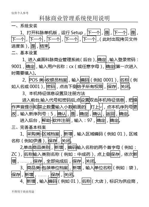
科脉商业管理系统使用说明一、系统安装二、基本设置1(后台)9001cx第一次进入2如人名或0001)3三、完善基本档案1),区域),4四、业务工作(一)库存管理12345、查实时库存输入编码(或直接在后侧选择相应类别)。
6。
78即自动计算出现差错(二)销售相关1734查找,(三)前台POS端设置1、前台零售操作步骤1POS,按的数字,完成一次交易。
(2,再按入条码,按,再按。
)会员卡收款:先输入所购买商品,按,输入卡号,按,完成退货。
(7)退出POS在当前收款状态下,按号即为小票号。
销售状态,按,条码,店内码作废,退货结算,人民币,前台日结,会员卡上面提到的设置,都是指第一次进入时需要设置,再次进入时是指在键盘上对应的按键。
在收银界面按某键时,提示XXX键没有定义,只要按一下,就好了。
仅供个人参考仅供个人用于学习、研究;不得用于商业用途。
For personal use only in study and research; not for commercial use.Nur für den persönlichen für Studien, Forsc hung, zu kommerziellen Zwecken verwendet werden.Pour l 'étude et la recherche uniquement à des fins personnelles; pas à des fins commerciales.толькодля людей, которые используются для обучения, исследований и не должны использоваться в коммерческих целях.以下无正文。
科姆龙2000 变频器 参数表 说明书
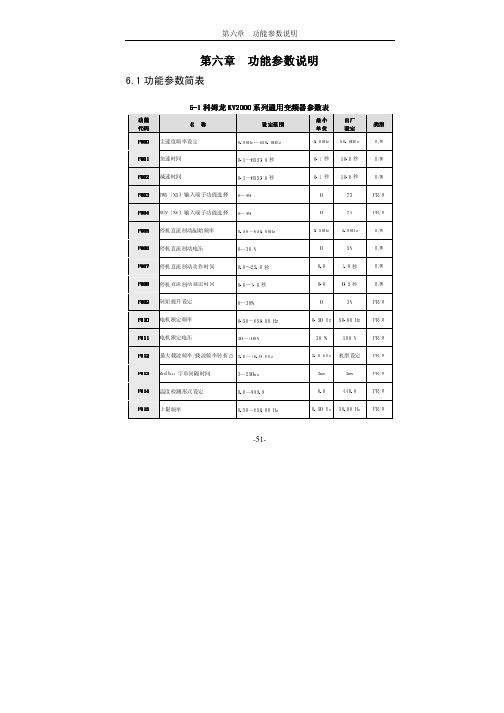
-51-第六章 功能参数说明功能参数说明6.1功能参数简表6-1科姆龙KV KV22000系列通用变频器参数表系列通用变频器参数表功能功能 代码代码 名 称称设定范围设定范围最小最小 单位单位 出厂出厂 设定设定 类型类型 F00F0000 主速度频率设定 0.00Hz~650.00Hz 0.00Hz 50.00Hz R/W F001F001 加速时间 0.1~6553.0秒 0.1秒 10.0秒 R/W F00F0022 减速时间0.1~6553.0秒 0.1秒 10.0秒 R/W F003F003 FWD(X5)输入端子功能选择 0~99 0 73 FR/W F00F0044 REV(X6)输入端子功能选择 0~990 74 FR/W F00F0055 停机直流制动起始频率 0.50~650.00Hz 0.50Hz 5.00Hz R/W F00F0066 停机直流制动电压 0~30 % 0 5% R/W F00F0077 停机直流制动动作时间 0.0~25.0秒 0.0 1.0秒 R/W F00F0088 停机直流制动延迟时间 0.0~1.0秒 0.0 0.5秒 R/W F00F0099 转矩提升设定 0~30%3%FR/W F0F0101010 电机额定频率 0.50~650.00 Hz 0.50 Hz 50.00 Hz FR/W F0F0111111 电机额定电压30~100%30 %100 %FR/W F0F0121212 最大载波频率/载波频率转折点 2.0~16.9 KHz 2.0 KHz 机型设定 FR/W F0F0131313 Modbus 字串间隔时间 3~250ms 3ms 3ms FR/W F0F0141414 温度检测形式设定 0.0~999.9 0.0440.8FR/W F0F0151515 上限频率0.50~650.00 Hz0.50 Hz 50.00 HzFR/WF0F0161616 下限频率 0.00~650.00 Hz 0.00 Hz 0.00 Hz FR/W F0F0171717 跳跃频率 0.00~650.00 Hz 0.00 Hz 0.00 Hz R/W F0F0181818 跳跃频率范围 0.00~5.00 Hz 0.00 Hz 0.00 Hz R/W F0F0191919 点动频率 0.00~650.00 Hz 0.00 Hz 10.00 Hz R/W F0F0202020 点动频率加减速时间 0.1~25.0秒 0.1秒 10.0秒 R/W F0F0212121 阶段1运行频率 0.00~650.00 Hz 0.00 Hz 0.00 Hz R/W F0F0222222 阶段1加速时间 0.1~6553.0秒 0.1秒 10.0秒 R/W F023 阶段1减速时间 0.1~6553.0秒 0.1秒 10.0秒 R/W F023F024 阶段2运行频率 0.00~650.00 Hz 0.00 Hz 0.00 Hz R/W F024F025 阶段2加速时间 0.1~6553.0秒 0.1秒 10.0秒 R/W F025F0F0262626 阶段2减速时间 0.1~6553.0秒 0.1秒 10.0秒 R/W F0F0272727 阶段3运行频率 0.00~650.00 Hz 0.00 Hz 0.00 Hz R/W F0F0282828 阶段3加速时间 0.1~6553.0秒 0.1秒 10.0秒 R/W F0F0292929 阶段3减速时间 0.1~6553.0秒 0.1秒 10.0秒 R/W F0F0303030 停机方式 0~1 0 0 R/W F0F0313131 禁止反转 0~1 0 0 R/W F0F0323232 功率因数/滤波常数 50.00~99.99 50.00 85.20 FR/W F0F0333333 启动放电刹车回路 0~2 0 0 R/W F0F0343434 低(过)电压故障后再启动 0~1 0 0 R/W-52-F0F03535失速过流点 10~200 10 200 % R/W F0F0363636 暂时停止输出时间 0.1~5.0秒 0.1秒 0.5秒 R/W F0F0373737 模拟输出AM 0~17 0 0 R/W F0F0383838 模拟输出AM增益 0~255 0 255 R/W F0F0393939 运行控制方式选择 0.0~9.9 0.0 0.0 R/W F0F0440频率设定选择 0.00~99.99 0.00 8.08 R/W F0F0414141 X1输入端子功能选择 0~99 0 0 R/W F042 X2输入端子功能选择 0~99 0 0 R/W F042F043 X3输入端子功能选择 0~99 0 0 R/W F043F044 X4输入端子功能选择 0~99 0 0 R/W F044F0F0454545 开路集电极输出Y1功能选择 0~99 0 0 R/W F0F0464646 开路集电极输出Y2功能选择 0~99 0 0 R/W F0F0474747 继电器输出端子功能选择 0~99 0 4 R/W F0F0484848 输出电流检出水平 0~150% 0 100 % R/W F0F0494949 频率检出水平 0.00~650.00 Hz 0.00 Hz 30.00 Hz R/W F0F0505050 频率检出允许范围 0.00~25.0 Hz 0.00 Hz 5.0 Hz R/W F0F0515151 电子热继电器动作时间 0~120秒 0 60秒 R/W F0F0525252 电机极数 2~12极 2极 4极 FR/W F0F0535353 齿轮比例 0~250% 0 100 % R/W-53-F0F05454监视模式选择 0~250 0 0 R/W F0F0555555 模拟转换器输入信号选择 0~250 0 0 R/W F0F0565656 模拟转换器输出资料 0~1023 0 M F0F0575757 输出频率(Hz) 0.00~650.00 Hz 0.00 Hz Hz M F0F0585858 输出转速(rpm) 0 rpm rpm/ Krpm M F0F0595959 直流母线电压 Vdc M F0F0606060 输出电压 Vrms M F061 电流及其他状态显示 M F061F062 散热器温度 0~100℃ ℃ M F062F063 数字输入端子状态 0.0.0.0~1.1.1.1 0.0.0.0 0.0.0.0 M F063F0F0646464 控制端子状态 0.0.~1.1 0.0. 0.0. M F0F0656565 数字输出端子状态 0.0.0~1.1.1 0.0.0 0.0.0 M F0F0666666 保留F0F0676767 运行模式选择 0~4 0 1 FR/W F0F0686868 无感矢量电压补偿 0~30 0 10 FR/W F0F0696969 滑差补偿系数F1/F2 0.0~99.99 0.0 50.50 % FR/W F0F0707070 模拟输入增益 0.0~100 0.0 50 % R/W F0F0717171 计时器(TIMER)动作时间 0.2~6553.0 0.2 5.0秒 R/W F0F0727272 简易PLC自动运行选择 0~6 0 0 R/W-54-F0F0737373 自动运行第一段时间设定 0.1~6553.0秒 0.1秒 15.0秒 R/W F0F0747474 自动运行第二段时间设定 0.1~6553.0秒 0.1秒 15.0秒 R/W F0F0757575 自动运行第三段时间设定 0.1~6553.0秒 0.1秒 15.0秒 R/W F0F0767676 自动运行第四段时间设定 0.1~6553.0秒 0.1秒 15.0秒 R/W F0F0777777 自动运行第五段时间设定 0.1~6553.0秒 0.1秒 15.0秒 R/W F0F0787878 电机额定容量 10~100 % 10 100 % FR/W F0F0797979 再启动方式选择 0~3 0 0 R/W F080 速度寻找动作水平 10~200 % 10 150 % R/W F080F081 速度寻找时减速时间 0.1~25.0秒 0.1秒 2.0秒 R/W F081F0F0828282 速度寻找时电压恢复时间 0.1~5.0秒 0.1 0.5秒 R/W F0F0838383 IGBT保护时间 2.0~25.0us 2.0us 3.0us FR/W F0F0848484 输入交流电压 40~1000 V 40 380V FR/W F0F0858585 变频器额定电流 0.5~3000.0 A 0.5 机型设定 FR/W F0F0868686 电流显示值的增益调整 70~140 70 100 FR/W F0F0878787 电压显示值的增益调整 70~140 70 100 FR/W F0F0888888 最大输出电压 30~100 30 100 % FR/W F0F0898989 V1端子输入最低值 0~1023 0 12 FR/W F0F0909090 V1端子输入最高值 0~1023 0 1012 FR/W F0F0919191 V2端子输入最低值 0~1023 0 12 FR/W-55--56-F0F09292 V2端子输入最高值 0~1023 0 780 FR/W F0F0939393 通讯格式/通讯地址 0.01~99.99 0.01 0.01 FR/W F0F0949494 数据初始化 0~250 0 0 R/W F0F0959595 参数写保护 0~2 0 0 R/W F0F0969696 开放特殊参数设定 0~1 0 0 R/W F0F0979797 软件版本机型设定 R F0F0989898 I 灯亮时欲监视的参数 0~99 0 61 R/W F099F099 Hz 灯亮时欲监视的参数0~9957R/W-57-6.2 参数功能详细说明F000 F000 主速度频率设定主速度频率设定主速度频率设定设定范围设定范围::0.00 0.00 ~~ 650.00Hz 650.00HzF000是存储器内的主要运行频率设定。
科脉实施手册(新)

收银管理制度。包括收银工作时间、班次安排、常见业务处理方法、敏感操作权限管理、收银对帐、后台报表统计等
退换货处理流程。换货作一退一销处理。
减价品处理流程。应加强电脑系统之外的审批控制。
大宗购物/批发流程。不同客户需求不同,百货零售店在门店销售出库,而电器、家俱经销商对大件商品一般由配送中心送货。制订流程时应考虑用户的业态、收款规定等。
乙方项目经理应由具有较丰富商业经验和电脑系统知识的人员担任,必须具备一定的沟通表达能力,可以和甲方业务人员顺利交流看法,协助甲方制订管理制度,培训软件系统的使用方法。
2.
项目实施组的人员组成和职责确认之后,可以开始制定项目实施计划,示例如下:
项目实施计划表
项目名称:制表时间:
实施阶段
工作内容
承担人
备注
2.
为保障项目顺利实施,贴近用户的实际需求,乙方项目经理应积极与甲方业务、财务负责人沟通,组建项目小组,成员一般是商场各部门的负责人或业务骨干,熟悉本部门的情况。乙方项目经理召集项目小组的成员,对他们进行深度的培训,增加他们对科脉系统的理解。让这些主要使用者了解这个系统是如何运作,可以提供哪些功能;在此基础上,分析、对比科脉系统流程和商场目前操作流程的差异,讨论现有的手工操作流程如何在科脉系统中实现,用科脉系统的业务流程来要求和规范各个部门的业务。
IT部工作制度。一个重要的方面是制订日常和月度数据维护计划,包括日结、月结、数据备份与数据删除等。
以上内容可视用户的经营管理方式的不同有所增减。
如果用户方已有这些流程的制度文件,可以考虑对原文件作适当的变更,加入有关电脑系统的内容,将原流程中涉及电脑操作的内容、步骤、方法、注意事项、异常处理等等作出统一明确的规定。
科脉

科脉·PDA仓储系统用户手册目录1、责任声明 (1)2、适读对象 (1)3、手册简介 (1)4、手册字体和符号规范 (1)第一章系统初始化及配置 (1)1.1、网络配置 (1)1.2、系统的配置 (2)1.2.1、参数配置 (2)1.2.2.业务配置 (3)1.2.3.打印配置 (4)1.2.4.系统信息 (5)第二章:入库 (7)2.1、验收入库 (8)2.2、采购退货 (11)2.3、单据下载 (15)2.4、单据上传 (15)第三章:批发 (15)3.1、客户 (15)3.2、批发订单 (19)3.3、批发销售 (21)3.4、批发退货 (26)3.5、单据上传 (27)3.6、单据下载 (27)3.7、客户上传 (27)第四章:调拨 (27)4.1、调拨 (27)4.2、调拨转入 (29)4.3、要货申请 (30)4.4、单据下载 (32)4.5.单据上传 (32)第五章:配送收货 (32)5.1、配送管理 (32)5.2、收货管理 (34)5.3、单据下载 (35)5.4、单据上传 (35)第六章:盘点 (35)6.1、批次盘点 (35)6.2、快速盘点 (38)6.3、参数设置 (39)6.4、盘点上传 (39)6.5、批次下载 (39)第七章:信息查询 (40)7.1、库存查询 (40)7.2、商品查询 (40)7.3、会员价查询 (41)7.4、零售特价查询 (42)第八章:系统管理 (43)8.1、数据管理 (43)8.2、系统配置 (47)8.3、系统升级 (47)8.4、数据上传 (47)8.5、资料下载 (48)8.6、设置时间 (49)8.7、打开网络 (50)8.8、关闭网络 (50)前言1、责任声明本手册包含的信息代表科脉公司目前对手册所涉及内容的观点,由于用户需求、市场和产品情况的不断变化,手册中的信息并不代表科脉公司未来的观点,科脉公司不能保证本手册信息在未来时间的有效性。
CTT2000LM操作台手册资料

CTT2000L/M专用数字通信系统操作台手册中国计算机软件与技术服务总公司电话:市电(010) 62174278 , 62173406路电(021) 49580 , 74666,1 CTT-2000L/M 调度台 (4)2 调度台硬件结构介绍 (4)2.1 键盘调度台板面介绍 (4)2.2 键盘调度台侧面介绍 (6)2.3 键盘调度台内部结构介绍 (6)3 调度台操作说明 (7)3.1 启动或关闭系统 (7)3.2 系统运行主屏幕 (7)3.2.1 菜单操作预说明 (8)3.2.2 进入运行 (8)3.2.3 调节音量 (9)3.2.4 调节亮度 (10)3.2.5 查看数据 (10)3.2.5.1 退出 (11)3.2.5.2 未接电话 (11)3.2.5.3 通话记录 (11)3.2.5.4 系统数据 (12)3.2.5.5 清未接电话 (12)3.2.5.6 清理全部记录 (13)3.2.6 播放录音 (13)3.2.6.1 顺序播放录音 (14)3.2.6.2 选择播放录音 (14)3.2.7 设置数据 (15)3.2.7.1 退出 (16)3.2.7.2 修改单呼键 (16)3.2.7.3 修改组呼键 (17)3.2.7.4 增加单呼键 (18)3.2.7.5 增加组呼键 (19)3.2.7.6 删除呼叫键 (19)3.2.7.7 修改口令 (20)3.2.8 设置数据 (21)3.2.8.1 退出设置系统 (21)3.2.8.2 调度台请求加载数据 (21)3.2.8.3 调度台数据初始化 (22)3.2.9 测试系统 (22)3.2.9.1 0.退出设置系统 (23)3.2.9.2 1. LED灯测试 (23)3.2.9.3 2. 键盘测试 (23)3.2.9.4 3. U接口环回测试 (24)3.2.9.5 4. 数据FLASH测试 (24)3.2.9.6 5. 录音FLASH测试 (25)3.2.9.7 6. 系统复位 (25)3.3 功能键说明(12个) (25)3.3.1 自动 (25)3.3.2 键权 (25)3.3.3 转移 (26)3.3.4 强制 (26)3.3.5 录音 (26)3.3.6 放音 (26)3.3.7 主辅 (26)3.3.8 保留 (26)3.3.9 会议 (27)3.3.10 全呼 (27)3.3.11 挂机 (27)3.3.12 应答 (27)3.4 系统基本工作 (28)4 附录 (29)1CTT-2000L/M 调度台调度台是调度员进行调度指挥的操作平台,调度员通过调度台上的各种按键进行各种调度操作,如应答来话、转移或保持来话、呼叫用户、召集会议等。
科脉及秤软件操作步骤
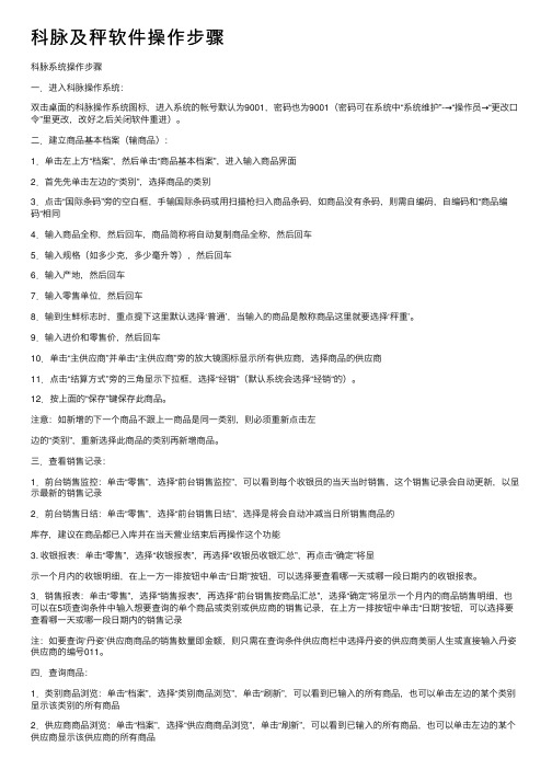
科脉及秤软件操作步骤科脉系统操作步骤⼀.进⼊科脉操作系统:双击桌⾯的科脉操作系统图标,进⼊系统的帐号默认为9001,密码也为9001(密码可在系统中“系统维护”-→“操作员→“更改⼝令”⾥更改,改好之后关闭软件重进)。
⼆.建⽴商品基本档案(输商品):1.单击左上⽅“档案”,然后单击“商品基本档案”,进⼊输⼊商品界⾯2.⾸先先单击左边的“类别”,选择商品的类别3.点击“国际条码”旁的空⽩框,⼿输国际条码或⽤扫描枪扫⼊商品条码,如商品没有条码,则需⾃编码,⾃编码和“商品编码“相同4.输⼊商品全称,然后回车,商品简称将⾃动复制商品全称,然后回车5.输⼊规格(如多少克,多少毫升等),然后回车6.输⼊产地,然后回车7.输⼊零售单位,然后回车8.输到⽣鲜标志时,重点提下这⾥默认选择‘普通’,当输⼊的商品是散称商品这⾥就要选择‘秤重’。
9.输⼊进价和零售价,然后回车10.单击“主供应商”并单击“主供应商”旁的放⼤镜图标显⽰所有供应商,选择商品的供应商11.点击“结算⽅式”旁的三⾓显⽰下拉框,选择“经销”(默认系统会选择“经销“的)。
12.按上⾯的“保存”键保存此商品。
注意:如新增的下⼀个商品不跟上⼀商品是同⼀类别,则必须重新点击左边的“类别”,重新选择此商品的类别再新增商品。
三.查看销售记录:1.前台销售监控:单击“零售”,选择“前台销售监控”,可以看到每个收银员的当天当时销售,这个销售记录会⾃动更新,以显⽰最新的销售记录2.前台销售⽇结:单击“零售”,选择“前台销售⽇结”,选择是将会⾃动冲减当⽇所销售商品的库存,建议在商品都已⼊库并在当天营业结束后再操作这个功能3. 收银报表:单击“零售”,选择“收银报表”,再选择“收银员收银汇总”,再点击“确定”将显⽰⼀个⽉内的收银明细,在上⼀⽅⼀排按钮中单击“⽇期”按钮,可以选择要查看哪⼀天或哪⼀段⽇期内的收银报表。
3.销售报表:单击“零售”,选择“销售报表”,再选择“前台销售按商品汇总”,选择“确定”将显⽰⼀个⽉内的商品销售明细,也可以在5项查询条件中输⼊想要查询的单个商品或类别或供应商的销售记录,在上⽅⼀排按钮中单击“⽇期”按钮,可以选择要查看哪⼀天或哪⼀段⽇期内的销售记录注:如要查询‘丹姿’供应商商品的销售数量即⾦额,则只需在查询条件供应商栏中选择丹姿的供应商美丽⼈⽣或直接输⼊丹姿供应商的编号011。
电源专家仪表2000网关卡套件快速起始指南说明书

Power Xpert® Meter 2000 GatewayCard KitT able of ContentsRemove the Meter From Service . . . . . . . . . . . . .2Disconnect Power Connections, CTs, andModbus . . . . . . . . . . . . . . . . . . . . . . . . . . . . . . .2Remove Meter from Panel. . . . . . . . . . . . . . . . .2Locate the Meter on the Bench. . . . . . . . . . . . .2Install the Gateway Card . . . . . . . . . . . . . . . . . . . .3Check Meter Firmware . . . . . . . . . . . . . . . . . . .4Connect to the Meter for Firmware Upgrade . .4Upgrade the Firmware . . . . . . . . . . . . . . . . . . . .4Configure the Gateway Card . . . . . . . . . . . . . . . .5Check Gateway Card Indicators . . . . . . . . . . . . .5Configure Network Access for the Gateway Card using a Local PC . . . . . . . . . . . . . . . . . . . . . . . . .5Verify the IP Address . . . . . . . . . . . . . . . . . . . . .7Network Access . . . . . . . . . . . . . . . . . . . . . . . . .7If Y ou Need to Restart The Gateway Card . . . . .7Additional Information . . . . . . . . . . . . . . . . . . . .8Reinstall the Meter . . . . . . . . . . . . . . . . . . . . . . . .82Quick Start Guide IL02601011EEffective December 2011Power Xpert® Meter 2000 Gateway Card KitEATON CORPORATION Remove the Meter From ServiceTurn power off at the breaker feeding the meter . There may be more than one breaker . Use local safety procedures such as “Lock out/ Tag out” to ensure the breaker(s) is not inadvertently energized . Ensure the high power connections on the meter are de-energized .•Current sensing wires may be connected directly to the load by simply passing the current carrying conductors (load or Current Transformers) directly through the meter . There is no physical connection to the meter .•Current sensing wires may be connected directly to the meter by attaching the current carrying conductors to “current gills” or quick connect terminals on the meter .Then remove or disconnect the current sensing wires from the meter .H WARNING!USE CAUTION TO ENSURE THE CURRENT THROUGH THE CTS IS OFF OR SUIT-ABLE PROTECTION IS IN PLACE TO PREVENT CONTACT WITH THE LEADS FROM THE CT.ENSURE THE CONTROL OR LOGIC POWER TO THE METER IS DE-ENERGIZED. THE VOLTAGE AT THESE TERMINALS IS THE LOCAL AC VOLTAGE.Disconnect Power Connections, CTs, and Modbus1 . Remove the large 13 position connector on the back of the meter .2 . If the installation is being done on an operational meter, this connector must be removed before installing the Gateway Card . Removing this connector will remove power to the meter . The Gateway Card is not designed to be hot-pluggable (installed with power on) .3 . If an extra 13 position connector is not available, make note of where the wires are connected to the 13 pin connector . Y ou will need this information when re-connecting the wires . Then remove the wires from the 13 position connector and replace the connector into the meter .Figure 1. 13 and 6 position connectors13 position GND L(+) 6 position Remove Meter from PanelWhen removing the meter keep the mounting hardware (screws, washers, etc .) in a safe place for use when re-installing the meter .For ANSI installations remove the four nuts and washers .Figure 2. Removing the four nuts and washersFor DIN installations remove the two screws and mounting brackets .Figure 3. Removing the DIN mounting bracketsFor DIN rail installations pull down on the mounting clips to release the meter .Figure 4. T ransducer version of meter mounted on DIN railLocate the Meter on the BenchThe installation procedure requires local power and an activeEthernet connection . To provide power to the meter, it may be usefulFour mounting nuts and lock washersMounting brackets and screws3Quick Start Guide IL02601011EEffective December 2011Power Xpert® Meter 2000 Gateway Card KitEATON CORPORATION to build an Aux cable to GND, L(+) and N(-) using a 13 position con-nector . This is particularly useful if installing many Gateway Cards .The Gateway Card must be installed in slot 2. If slot 2 is occu-pied, remove the card in slot 2 and place it into slot 1 . Otherwise,remove the option card cover over slot 2 . Retain the screws .Install the Gateway CardI C AUTION!USE LOCAL ELECTROSTATIC DISCHARGE PROTECTION OR TOUCH A SUITABLY GROUNDED METAL SURFACE TO DISCHARGE ANY STATIC ELECTRICAL CHARGE. FAILURE TO FOLLOW THESE GUIDELINES COULD CAUSE DAMAGE TO THE GATEWAY CARD.1 . Remove the Gateway Card from the protective wrap .2 . Locate the MAC address printed on the card . Record it here . MAC Address:_________________________________________The MAC address is on a small label and consists of 14 letters and numbers . It looks something like: 0020808500EF3 . Another MAC address label is included in that kit and should be applied to the flat area on top of the meter (above the meter’s infor-mation label) .Figure 5. Area for MAC address label4 . Verify the switch settings on the card . All switches should be in the off position .Figure 6. Card Switches Shown in the Off Position5 . Insert the Gateway Card into meter slot 2 using the meter’s built-in card guides (see the following figure) . Use care to correctly locate the card in the guides . Slide the card carefully into the meter until it stops . Gently push on the card until it “clicks” into place .Figure 7. Install Gateway Card into slot 26 . Secure the card by replacing the screws removed while removing the cover .7 . If available, connect the building Ethernet cable to the jack on the Gateway Card . Otherwise use a local Ethernet equipped PC and the seven-foot Ethernet cable shipped with this kit .8 . If available, connect the Modbus connector (6 position connector) that is attached to the Modbus network .9 . Attach the power cord . If an AUX power cord was assembled then insert the connector into the socket . Otherwise connect GND, L(+) and N(-) to the 13 position connector as indicated in the figure on page 2 .10 . A pply power to the power cord .11 . There are four indicator LEDs on the Gateway Card labeled:Status , DHCP , Ident , and Power . When power is first applied all the lights should be off for a few seconds and then the Power light will illuminate . This indicates the card has power and is running .12 . T here are two lights (LEDs) located on the Ethernet cable jack . If the Ethernet cable has an active Ethernet connection the light labeled Act may be flickering . The light labeled 100 will be lit if the Ethernet connection is active at 100 Mbps .Put MAC address I/O Card Guide Track4Quick Start Guide IL02601011EEffective December 2011Power Xpert® Meter 2000 Gateway Card KitEATON CORPORATION Figure 8. Location of LEDsCheck Meter FirmwareIf the meter firmware is lower than version 14, you must upgrade the firmware . Y ou can check the firmware version of a powered meter from the front panel .1 . Press menu .2 . Press the down button until Info is flashing (line A) .3 . Press enter .4 . An initial three-line display of values appears . After a few sec-onds, a second set of values appears . The firmware version number is in the middle line .5 . If the meter firmware version is 14 or greater, you do not needto upgrade the firmware and can proceed to Configure the Gateway Card on page 5 .6 . If you must upgrade the firmware, continue on with this proce-dure .7 . Press menu .8 . Press the down button until CfG is flashing (line A) .9 . Press enter .10 . P ress the down button until POrt is flashing (line A) .11 . Press enter .12 . T he Adr (address) screen appears . Record the address:13 . A ddress___________14 . P ress enter . The bAUD screen appears . Record the baud rate:15 . B aud rate:_________16 . P ress menu twice .Connect to the Meter for Firmware UpgradeThis procedure requires an RS-232 to RS-485 serial adapter, as you must connect to the meter through the RS-485 port .1 . Place the CD that accompanied your upgrade kit into the PC’s CD/DVD drive .2 . Install the Eaton Meter Configuration Software (double-click EatonMCSSetup .exe in the root folder of the Eaton Meter Configuration Software CD) .3 . After installation, launch the Configuration Software .4 . Click the Connect icon on the title bar or Connection > Quick Connect .5 . Make sure the Serial Port radio button is selected .6 . Enter the Device Address you previously recorded .7 . Select Baud Rate you previously recorded from the pull-down menu .8 . Select the port you are using from the pull-down menu . The Available Ports/All Ports radio buttons determine which port selec-tions the menu displays .9 . Select Modbus RTU from the Protocol pull-down menu .10 . S elect Flow Control: None .11 . Select Echo Mode: No Echo .Figure 9. Connection screen12 . C lick the Connect button . Y ou will see the Device Status screen .Figure 10. Device Status ScreenUpgrade the Firmware1 . At the Eaton Meter Configuration screen, select Tools > FlashMe. Y ou will see the following screen .Power LEDStatus LED5Quick Start Guide IL02601011EEffective December 2011Power Xpert® Meter 2000 Gateway Card KitEATON CORPORATION Figure 11. Firmware Update Dialog Box2 . Click Browse to locate the firmware update file on the CD .3 . Click Flash to update the firmware .4 . When the update is complete, click Exit to close the screen .otee:N If Flash Update fails, you will see a message to that effect . CheckDevice Status to see if your meter is in Boot Mode .•If the meter is in Boot Mode, clear the Starting from Run Mode box in the Flash Me screen and try flash updating the firmware again .•If the meter’s status is not displayed in the Device Status screen, the meter may be stuck in Boot Mode . If you are certain the com-munication settings are correct for the meter, try connecting to the meter using the following defaults:Address 001Baud Rate 9600ProtocolModbus RTUOnce you connect to the meter, you can try flash upgrading again .This concludes the firmware update . Y ou can now proceed to con-figure the Gateway Card .Configure the Gateway CardAn Ethernet connection is used for configuring the meter’s Gateway Card communication settings via a web browser . Y ou may need to contact your network administrator for some network and configura-tion information . In preparation, you will need to decide if the meter will be manually assigned a fixed (static) IP address or will be auto-matically assigned a fixed IP address by a DHCP server somewhere on the network . With either method the assigned network address must not change once the meter has been deployed . Changing the IP address will cause loss of communication until the associated cli-ent PCs change the corresponding meter’s IP addresses .Discuss with your network administrator whether you should manu-ally configure the meter with a static IP address (the dafault) or whether the DHCP server will assign one . For the DHCP server to provide a fixed IP address, your network administrator will need to know the MAC address assigned to the meter .H CAUTIONEATON STRONGLY RECOMMENDS USING A FIXED IP ADDRESS (THE DEFAULT) IF AN EATON PXS SYSTEM WILL BE ACCESSING THE METER. OTHERWISE,SHOULD THE IP ADDRESS CHANGE (AFTER A POWER OUTAGE, FOR EXAMPLE), PXS WILL NO LONGER BE ABLE TO ACCESS DATA FROM THE METER.Is DHCP going to be used to assign the IP address to your meter? ___ Y es ___ NoIf Yes :Provide the MAC address (previously noted on page 3) to the net-work administrator and record the fixed IP address the network administrator will assign to your meter in the DHCP server here:IP Address:The card will be configured remotely . Skip to the section entitled Verify the IP addressIf No :Record the following information provided by the network adminis-trator here:IP Address: _______________________________________________ Subnet Mask:______________________________________________ Default Gateway:___________________________________________ Primary DNS Server IP Address______________________________Secondary DNS Server IP Address____________________________Check Gateway Card IndicatorsFirst, ensure power is applied to the meter .There are four indicator LEDs on the Gateway Card labeled: Status , DHCP , Ident , and Power . When power is first applied all the lights should be off for a few seconds and then the Power light will illumi-nate . This indicates the card has power and is running .Configure Network Access for the Gateway Card using a Local PCY our network administrator either provided an IP address, a subnet mask, and a default gateway (which you entered in the previous sec-tion) or has decided to assign an address via DHCP . This information must be entered into the Gateway Card using a local PC, such as a laptop .This method requires a PC with the following:• an Ethernet port• an Ethernet cable (a seven-foot cable is provided in the kit) •a Java-enabled web browser, such as Microsoft Internet Explorer versions 7, 8, or 9 .•an installed version 6 or greater JAVA J2SE JRE (Java Runtime Environment) . If not already installed, when you connect to the meter you’ll be given the option to navigate to the Sun Java web-site and download the JRE .1 . On the PC, launch the Java Control Panel screen (available through the Windows Control Panel ) .2 . On the General tab, click the Settings button under Temporary Internet Files .6Quick Start Guide IL02601011EEffective December 2011Power Xpert® Meter 2000 Gateway Card KitEATON CORPORATION Figure 12. Settings Button3 . Ensure the Keep Temporary Files on My Computer check box is cleared .Figure 13. Keep Temporary Files on My Computer check box4 . Connect the PC to the Gateway Card through the seven-foot Ethernet cable shipped with the kit .There are two green lights (LEDs) located on the Gateway Card’s Ethernet port . If the Ethernet cable is connected to an activeEthernet port on the PC both lights should be illuminated (the light labeled Act may be flickering reflecting network activity) .5 . The card’s default Ethernet IP address is 192 .168 .1 .1 . Set the PC’s address to an address on the same subnet, such as 192 .168 .1 .100 .To do this, use the following steps:1 . Click Window’s Start .2 . Choose either Settings > Control Panel (Windows 2000) or Control Panel (Windows XP) .3 . In the Control Panel , click Network Connections and right-click Local Area Connection . Select Properties from the shortcut menu .4 . Click the Properties button .5 . In the Properties dialog box, select Internet Protocol (TCP/IP) and click the Properties button .6 . In the Internet Protocol (TCP/IP) Properties dialog box, select Use the following IP address and enter the following in the IP address field: 192.168.1.1007 . Click OK throughout the various dialog boxes .6 . Launch your Java-enabled web browser and navigate to the fol-lowing IP address: 192.168.1.1If an information screen appears stating the certificate cannot be verified and asking if you want to run anyway, select run.Java will load and then the meter’s Home page will appear .Figure 8. Loading Page7 . Click the Setup button or the Setup Meter link . The Setup page will appear .7Quick Start Guide IL02601011EEffective December 2011Power Xpert® Meter 2000 Gateway Card KitEATON CORPORATION Figure 9. Meter Home Page8 . Locate and click the open icon to the left of the Quick Setup fold-er . The folder opens to show two subfolders: Meter and Network .Figure 10. Opening the Quick Setup Folder9 . Click the Network folder . 10 . C lick the Edit button .Figure 11. Edit Button (on the right of the page)11 . A Login dialog box appears .12 . T he default Username is admin and the default Password is admin . Log in using these credentials .Figure 12. Login dialog13 . Configure the card for the settings specified by your network administrator . Y ou can also enter such optional information as the meter’s location, who to contact in case of problems, etc .14 . W hen you’ve completed configuration, click the OK button .15 . T he new IP address will take effect shortly after clicking OK . Communication with the PC will then be lost . Y ou can continue to configure the meter after it is connected to your LAN .16 . R efer to the PXM 2000 Meter User and Installation Guide (IM02601001E) for additional configuration details .17 . Disconnect the Ethernet cable to the PC and connect the meter to the LAN .otee:N Remember to reconfigure the PC’s network settings for your LAN .Verify the IP Address1 . If the meter has power the display should be showing normal data, such as voltage, current, etc .2 . Push the menu button on the face of the meter . The main menu screen appears .3 . Push down repeatedly until IP blinks .4 . Push enter and the meter’s IP address appears, which should appear something like the following:010.2 22.05 1.066In this example the IP address is 010.222.051.066 . This should match the address the network administrator provided for this meter . 5 . Push menu to return to the main menu .Network AccessOnce the network IP address is known, most meter functions and configuration can be done via the network . Use a networked client PC running version 6 or greater of the JAVA J2SE JRE and a Java enabled browser such as Internet Explorer version 7, 8, or 9 to navi-gate to the meter’s IP address . See the meter’s complete user’s manual for additional information .If You Need to Restart The Gateway CardY ou can restart the Gateway Card through a momentary push-button switch accessed through a small hole in the face plate of the Gateway Card . Although this is not used in normal operations, this switch allows you to restart the Gateway Card in the meter . The Gateway Card restart push-button switch is located behind the hole in the card face plate closest to the LED labelled DHCP . This switch is used to restart just the Gateway Card (not the meter) should it be necessary to recover from some abnormal condition .Momentarily press the switch by pushing a small device into the hole to activate the switch .Notee: It may take around five minutes before the meter pages begin to display values .Quick Start Guide IL02601011EEffective December 2011Power Xpert® Meter 2000 Gateway Card KitEaton CorporationElectrical Group1000 Cherrington ParkwayMoon Township, PA 15108United States877-ETN-CARE (877-386-2273)© 2011 Eaton Corporation All Rights Reserved Printed in USA Publication No. IL02601011E December 2011PowerChain Management is a registered trademark of Eaton Corporation.All other trademarks are property of theirrespective owners.PXM 2000 Meter User and Installation Guide (IM02601001E) on theThe guide can also be found at http://Reinstall the MeterRefer to the meter documentation for a more detailed description of installing and wiring the meter . The following is merely an overview of the steps you’ll need to perform .1 . Turn power off to the 13 position connector . If an AUX cable was used then remove the 13 position connector . Else, disconnect the GND, L(+), and L(-) wires from the 13 position connector . See the figure on page2 .2 . If a Modbus network was connected remove the six position net-work connector .3 . Return the meter to the mounting panel using any hardware removed in previous steps . See the figures on page 2 .4 . Reconnect the current sensing (CT or direct connections) wires .5 . If an AUX cable was not used, reconnect the wires to the 13 position connector . Otherwise plug the wired connector into the meter .6 . Reconnect the Modbus network using the six position Modbus connector .7 . Insert the Ethernet cable into the socket on the new Gateway Card . Be sure to route the cable away from any high voltage wires . Secure the cable in compliance with local electrical codes .8 . Take any necessary safety precautions in preparation for restoring power .9 . Turn the power on at the breaker(s) .10 . W atch the LEDs on the back of the Gateway Card . They should all turn off for a few seconds and then the right (Status) and the left (Power) lights should be illuminated to indicate the card has power and has started correctly . See the figure on page 4 for the location of the LEDs .。
XK-2000 显示控制器使用手册

XK-2000 显示控制器使用手册本手册用于皮带机积算系统在安装和操作前请仔细阅读本手册并严格遵守设备操作规范南京文佳机电设备有限公司目录1、仪表概述 (2)2、技术规范 (5)3、仪表安装 (9)4、仪表接线 (10)5、操作运行 (20)6、系统校准 (31)7、控制调整 (49)8、参数说明 (50)第一章 XK-2000 概述1.1 功能简介:XK-2000 是以美国CYGNAL公司推出的高速、高性能混合信号处理单片计算机为核心而设计的多功能显示控制仪表,可以配合螺旋给料机、皮带机、称重料斗等使用。
仪表检测来自控制设备上的各种传感器信号,经过处理后在液晶显示器(4行汉字显示器)上显示、远程显示或通过数字通讯口传输给上位计算机显示,也可输出模拟量mA信号、继电器工作状态及报警输出信号。
XK-2000 仪表可应用于计量(控制)皮带机、固体流量计、质量流量计、质量加料机、称重加料机、减量喂料机。
XK-2000带两个隔离的RS485通讯接口:采用独立的多功能通信协议,并支持MODBUS 协议(附数据地址表)。
1.2 性能特点:●汉字显示菜单式用户操作界面:128×64点阵液晶显示器,四行汉字显示,六键操作系统。
●丰富的I/O资源:六个可编程开关量输入六个可编程继电器输出一路可用于PID控制的模拟量输入二路16位D/A(PWM)用于控制、流量、重量、速度的电流选择输出。
二路PID(0 ~ 20mA)电流控制输出●双路数字通讯接口:二个隔离的RS-485接口,用于:通讯口1、2,皆可选择专用独立的多功能通信协议及兼容的标准MODBUS 通讯协议。
通讯机器号:0 ~ 999数据传输率:0.3kbit/s ~ 115.2kbit/s。
多功能控制系统:软件集成多功能控制系统,可根据不同的工艺应用要求及称重方式选择不同的控制系统功能。
仪表控制具有手、自动选择。
自动清零(皮带秤自动整圈)、称重传感器满量程校准、流量校准功能。
KM V2 IC卡版本的升级和使用

KMJXC V2.0非IC卡版本升级为IC卡版KMJXC V2.0/V3.0 IC卡版本有关IC卡功能的使用说明1,设备支持1.1 IC卡读写器明华RD系列接触式IC卡读写器,软件测试用的具体型号为“M&W RD-ET 外置推推式读写器(MEMORY卡)”。
德生科技TSW-F2-21.2 IC卡SIEMENS 4442。
2,IC卡读写器挂接主机的端口COM1, COM2, COM3, COM43,科脉后台软件的使用使用科脉后台软件主要完成:设置IC卡的客户密码,初始化IC卡,发卡,充值,查询余额,相关查询报表等功能。
3.1设置IC卡的客户密码在‘基本档案’-‘会员卡浏览’中,先设置IC卡读写器所接的主机端口,按Ctrl+(即同时按下Ctrl 和 + 键)则出现按钮‘初始化密码’,点击此按钮进入‘设置IC卡的客户密码’窗口。
在工作密码中录入 T!E@C#H$ 共8个字符(即按下Shift 键后,再依次按T1E2C3H4键),然后点‘确定’按钮,则出现以下按钮初始化客户库密码:在工作密码中录入6位数字密码,然后点此按钮来设置客户自己的IC卡密码,此密码设定后即不能再更改,此功能也只需要设置一次。
恢复到出厂密码:此功能完成将已使用了客户IC卡密码的一张卡,恢复其密码到出厂密码。
插入IC卡后点此按钮即可,此功能正常情况下不使用。
核对出厂密码:此功能完成核对一张卡的密码是否是出厂密码,此功能正常情况下不使用。
核对客户密码:此功能完成核对一张卡的密码是否是客户自己设的密码,此功能正常情况下不使用。
3.2初始化IC卡在‘基本档案’-‘会员卡浏览’中,按Ctrl+(即同时按下Ctrl 和 + 键)则出现按钮‘初始化密码’,点击此按钮进入‘设置IC卡的客户密码’窗口。
在工作密码中录入 K!M@T#E$ 共8个字符(即按下Shift 键后,再依次按K1M2T3E4键),然后点‘确定’按钮,则出现按钮‘初始化卡’。
LK2000使用说明书

使用说明书
V1.0
武汉朗开电气有限公司 2014年4月
目录
1. 概述...........................................................................................................................................1 1.1. 关于本说明书 ...............................................................................................................1 1.2. 产品清单 .......................................................................................................................1
4. 接线说明.................................................................................................................................14 4.1. 接线要求 .....................................................................................................................14 4.2. 典型接线图 .................................................................................................................14
F200说明书

安装指南
型号:F200
neidnl [选取日期]
炥莱茵科技有限公司
目录
炥莱茵科技有限公司
一、产品概述及功能简介 ......................................................................................................................2 二、技术指标.........................................................................................................................................3 三﹑包装清单.........................................................................................................................................3
PICO 2000用户手册

PICO2000目录1 简介………………………………………………………… (2)1.1 概述 (2)1.2 标准功能 (2)1.3 可选功能 (2)1.4 存档备份系统模式 (3)1.5 音频记录选项 (3)2 总体概览…………………………………………………………43 启动PICO2000 监控系统 (4)3.1 登录 (4)3.2 主屏 (5)4 功能介绍………………………………………………………… (5)4.1 显示(多路复用功能) (5)4.1.1 显示控制面板 (5)4.1.2 1-画面显示模式 (6)4.1.3 4-画面显示模式 (6)4.1.4 8-画面分割模式 (8)4.1.5 16-画面显示模式 (8)4.1.6 快速缩放 (9)4.1.7 全屏显示 (9)4.2 序列 (9)4.3 远程在线观察和回放录象 (9)4.3.1 智能远程播放 (9)4.4 录像 (131)4.4.1存储驱动 (131)4.4.2 录象控制面板 (131)4.4.3 现行状态录象 (12)4.4.4 报警录象 (13)4.4.5 预置报警录象 (13)4.4.6 预定录象 (13)4.5 回放 (14)4.5.1 视频回放 (14)4.5.2 视频播放器 (14)4.5.3 视频回放控制 (15)4.5.4 回放速度控制 (16)4.5.5 帧模式打印和保存帧 (16)4.5.6 回放当前文件 (17)4.6 视频移动动态检测 (17)4.6.1 视频移动动态检测 (17)4.6.2 设置检测区域 (18)4.6.3 设置动态检测灵敏度 (18)4.6.4 检测间隔 (19)4.6.5 动态检测功能设为有效 (19)4.7 设置功能访问 (20)5 摄象机配置…………………………………………………………215.1 摄象机名称分配 (21)5.2 选中活动的已连接摄象机 (21)5.3 摄象机名称应用 (21)6 录象机设置…………………………………………………………226.1 录象参数 (22)6.1.1 帧速率 (22)6.1.2 预定录象的开始和结束时间 (22)6.1.3 现行状态录象 (22)6.1.4 报警录象 (23)6.2 预置报警录象 (23)6.3 工作日调度录象 (24)6.4 周末调度录象 (25)7 选项设定…………………………………………………………277.1 显示时序 (27)7.2 所有录象的图象分辨率 (28)7.3 录象模式选择 (28)7.4 连接摄象机音频 (29)7.5 操作设置 (30)7.6 口令设置 (31)8 备份功能…………………………………………………………318.1 通常模式 (31)8.2 存档模式 (31)8.3 更换驱动器仅用于操作中存档模式 (33)8.4 可移动驱动器的重新插入 (34)9 例行事务管理 (34)9.1 删除视频文件 (35)9.2 例行事务处理工具 (37)9.3 系统信息 (37)10 文件过多警告………………………………………………………3810.1 过多文件警告信息 (38)11 退出方式………………………………………………………… (39)11.1 退出 (39)11.2 在退出后录象 (39)11.3 关掉设备 (39)12 系统维护…………………………………………………………4012.1 时间表备份并删除视频文件 (40)13 报警输入连接 (40)14 云台控制解码器 (42)物件清单请确认您所购买的PICO2000王牌多媒体数字监控保安系统包装盒是否完整,如果包装有所损坏、或是有任何配件短缺的情况,请尽快与您的经销商联系。
点货宝在科脉软件中的相关设置(不带数字键盘)-liux-20100420

功能键介绍
• 按住“扫描/开机”键2秒。听到“滴”提示音后,显示开 机致词。进入显示初始界面。 • 按“入库/出库”键,可以切换入库和出库模式。 • 按“入库/出库”键2秒,进入“高级”模式,在高级模式 下,按“入库/出库”键2秒,进入普通模式。 • 按“盘点”键,进入盘点模式。 • 按“报损”键,进入报损模式。 • 按“发送/存储”键,则可切换传输模式,有实时、批量、 存储三种模式。 • 按“删除/关机”键3秒,点货宝关机。当商品扫描数量错 误时,按“删除/关机”键,右下角由普通变成删除,此 时再扫描商品,则数量会减少。 • 注:科脉软件中全部选择入库模式进行扫描。
• 存储模式:当连接不上或超过有效距离等,可以采用存储 模式扫描。按“发送/扫描”键可以从实时切换到存储模 式,商品扫描完后去电脑边进行导入,连接上以后,按 “发送/扫描”键,切换到批量模式,显示器显示“按扫 描键开始”,按“扫描/开机”键开始数据传输,传输完 成后在软件中进行导入。 • 如果某商品同样有上百或数量较多,要切换到高级模式, 按“入库/出库”键2秒,则右下角显示高级,进入高级模 式,按“发送/扫描”键,切换到存储模式,此时扫描完 商品后,可以手动增加或减少商品数量,按“盘点/”可以 递增,“报损/”递减,数量调好后按“扫描/开机”键,扫 描完后按“发送/存储”键切换到批量模式,显示器显示 “按扫描键开始”,再按“扫描/开机”键,然后再去软 件中导入。
科脉无线点货宝3K-T2000
使用说明
科脉无线点货宝3K-T2000
• 点货宝硬件介绍
• 点货宝设置 • 点货宝使用
点货宝硬件介绍
• 硬件:点货宝硬件包括便携式点货宝一台,无线 USB迷你接收器一台,充电器一个。(具体硬件 介绍摄像录制) • 功能键:入库/出库 • 盘点/ • 报损/ • 删除/关机 • 扫描/开机 • 发送/存储
Tek Know TC2000 温度测量系统说明书

TC2000COMBINES BENEFITS OF DRY BLOCK,LIQUID BATH,REFERENCE THERMOMETER ANDUP TO 20-POINT AUTOMATED CALIBRATION IN ONE UNITProbably the most complete temperature calibration system ever built, Tek Know’s TC2000 is designed to combine a dry block calibrator, a liquid bath calibrator and a reference thermometer in one uniquely portable design. Get all the advantages of both dry blocks and liquid baths in one calibrator.With the onboard WINDOWS CE computer and full graphic LCD display, the TC2000 is incredibly user friendly. Set up of an automated 20 point comparison calibration is menu driven and the TC2000 clearly displays temperature of both your sensor under test and if desired an optional external reference probe. In addition a graph of the sensor temperature and block temperature is displayed to accurately verify when stability is reached.The massive 2” diameter well allows for multiple probes to be inserted in either a liquid bath or metal block. The large calibration volume provides the TC2000 with excellent stability and accuracy. The TC2000 offers a temperature range of -40°C below ambient to +150°C.• Field Portability with Laboratory Accuracy• Largest Well Capacity 2” x 6”, (50mm X 155mm)• Stability Better than 0.005°C with Liquid Bath Option• Saves Time with Up To 20-Point Automated Comparison Calibration• Built Into Its Own Carrying CaseAs Dry Block• Quick change in well temperature• No mess or liquids• Good stability, <±0.02°C• Large well capacityAs Liquid Bath• Excellent stability, <±0.005°C• Excellent repeatability• Better capacity: accommodates sensors’ differentsizes and shapes• No need to make fittings for sensors• Small temperature gradientsWith Built-In Reference Thermometer• Easy to set up 20 point automatic calibration• Graphical 1/4 VGA display• RTD, T/C, V and mA test sensor inputs• Calibration reports produced according to ISO 9000• Comparison method optimizes possible thermometeraccuracy• Programmable correction tables for external references1.3.2.1. Main Menu — Calibration Mode•Calibration set-up from numeric keyboard or softkeys•Graphical or Numerical display for internal or external reference sensor and sensor under test•Switch test indication•When using TC2000 as a stirred liquid bath, you may set an appropriate impeller speed from this window2. Main Menu — ConfigurationIn this mode, the following set-ups are made:•20-Point automatic calibration•Temperature units in °C, °F and °K•Reference sensor internal or external•External reference sensor correction table•Sensor under test: T/C, Pt100 or 4-20mA•The TC2000 Helper guides you throughall configurations3. Main Menu — InformationIn this mode, you will get all necessaryinformation about the calibrator.•Next calibration date can be setby userEASY-TO-USE GRAPHICAL LCD DISPLAY WITH GUIDING MENUSTC2000Temperature Calibrator, -40°C below ambient to 150°C (302°F)$ 6,995TC2000-INS-L Liquid Insert for TC2000395TC2000-INS-B Undrilled metal block for custom probe diameters 210935-14-82Standard Reference Probe, -50°to 250°C (482°F)395FIELD TEMPERATURE RANGE -40°C below ambient to 150°C (-80°F below ambient to 302°F)RESOLUTION0.01°C GRADIENTS AT 95°C W/ WATER±0.06°CBETWEEN BOTTOM AND 25 MM FROM TOP STABILITY (30 MIN. AFTER NORMAL STABILIZATION)AS A DRY BLOCK±0.02°C AS A STIRRED LIQUID BATH ±0.005°C AS A STIRRED ICE BATH±0.001°C ACCURACY (WITH INTERNAL REF .)±0.3°CUNCERTAINTY (BEST)≤0.03°C (depending on ext. reference)WELL DEPTH 155 mm (6”)WELL DIAMETER 50 mm (2”)THERMOSTAT TEST yes INTERFACE RS232POWER SUPPLY110 VAC or 240 VAC (50/60Hz) (field selectable)OPERATING TEMPERATURE 0 to 40°C (32 to 104°F)DIMENSIONS16 x 10 x 14 in.WEIGHT (WITHOUT INSERTS)35 lb.SPECIFICATIONSINPUTS PORT ARANGE RES.ACCURACY PT100 2, 3 AND 4-WIRE*-50 to 800°C 0.01°C ±0.05°C ±0.009% rdg INPUTS PORT BPT100 2, 3 AND 4-WIRE*-50 to 800°C 0.01°C ±0.05°C ±0.009% rdg TYPE K -100 to 1370°C 0.1°C ±0.25°C ±0.03% rdg TYPE J -200 to 1200°C 0.1°C ±0.25°C ±0.03% rdg TYPE E -200 to 1000°C 0.1°C ±0.25°C ±0.04% rdg TYPE T -200 to 400°C 0.1°C ±0.25°C ±0.03% rdg TYPE S 0 to 1760°C 0.1°C ±0.25°C ±0.03% rdg TYPE R 0 to 1760°C 0.1°C ±0.25°C ±0.03% rdg TYPE B 400 to 1820°C 0.1°C ±0.25°C ±0.03% rdg TYPE N -200 to 1300°C 0.1°C ±0.25°C ±0.05% rdg VOLTAGE 0 to 10V 1µV ±2µV ±0.02% rdg CURRENT0 to 22mA 1µA ±2µA±0.02% rdg COLD JUNCTION**0 to 40°C0.1°C±0.25% rdgTC INPUT TEMPERATURE DRIFT ±0.009%/°C or 90 ppm/°C V AND MA INPUT TEMPERATURE DRIFT±0.0027%/°C or 27 ppm/°C* Pt100 conforms to IEC751 and temperature scaling of ITS-90** All thermocouple inputs are cold junction compensatedELECTRICAL SPECIFICATIONSORDERING INFORMATIONStandard Delivery includes: Metal Block Insert with 1/8”, 3/16”, 3/8” holes, RS-232 interface, tool for changing insert, NISTcalibration certificate, instruction manual, thermal switch test leads, and all necessary connectors for the reference thermometer.。
科脉
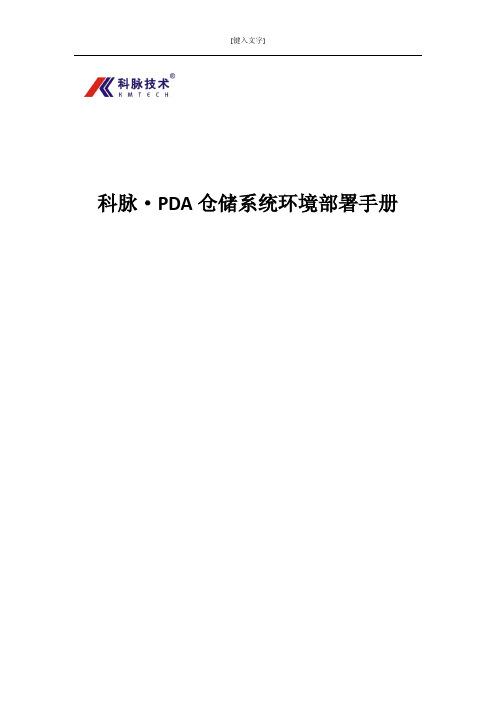
2.2、在安装包里找到相应的文件,进行安装
第一步:在仓储 PDA 安装包下,找到 Setup Cab 文件夹,并打开;
科脉•PDA 仓储系统环境部署手册 V1.0 第 5 页
第二步:在 Setup Cab 文件夹下找到 SQLserverCE31-EN.ExE,双击打开它;
第三步:计算机桌面状态下,点击左下角“开始”按钮,在里面找到“控制面板”并点击;
打开控制面板后,在里面找到“添加或删除程序” ,并双击打开:
科脉•PDA 仓储系统环境部署手册 V1.0 第 10 页
打开添加或删除程序界面后, 在该界面下找到 “添加/删除 windows 组件 (A) ” , 单击打开它;
©本手册的著作权属于深圳市科脉技术有限公司 版权所有,翻印必究。
手册版本
V1.0(2013-11-18)
公司信息
深圳市科脉技术有限公司 地 址:中国广东省深圳市南山区蛇口南海大道1057 号科技大厦二期A栋202 邮 编:518067 电 话:(+86-755) 82048690 传 真:(+86-755)82046886 网 址: E-mail:service@
第二步: 在 IIS 文件夹下根据客户自己服务器的操作系统解压对应文件在当前文件夹下, (注: 如果您的系统是 XP 的,请解压 iiS5.1-winxp.rar;如果您的系统是 server 2003,请解压 iis 6.0-win2003.zip)
科脉•PDA 仓储系统环境部署手册 V1.0 第 9 页
第一章 服务器配置安装
1、安装向导
1.1、进入科脉-3K-M9200 仓储安装包/升级包
CTT2000LM用户手册(维护分册)

CTT2000L/M专用数字通信系统用户手册(维护分册)中软网络技术股份有限公司路电:021-66002~66005市电:010-51866002~51866005传真:021-66001目录第一章 CTT2000L/M系统简介 (3)1.1 系统特点 (3)1.1.1 处理能力及可靠性 (3)1.1.3 接口丰富,组网能力强 (3)1.1.4 完善的测试和告警功能 (4)1.1.5 系统可维护性好 (4)1.2 系统功能 (5)1.2.1 接入铁路各项专用业务 (5)1.2.2 调度功能 (6)1.2.3 调度电话的组网方式 (6)1.2.4 通道保护功能 (6)1.2.5 集中管理维护功能 (8)1.2.6 用户交换机功能 (9)1.2.7 会议汇接机功能 (9)1.2.8 录音功能 (9)第二章系统组成 (10)2.1 后台主机 (10)2.2 操作台(前台) (15)2.3 集中维护管理终端 (16)2.4 录音系统 (17)2.4.1 数字集中录音系统 (17)2.4.2 键控操作台录音系统 (17)2.5 主要性能指标 (19)2.5.1 结构尺寸(单位mm) (19)2.5.2 工作电源 (19)2.5.3 环境要求 (21)2.5.4 接口指标 (21)第三章系统的安装与配置 (24)3.1、机柜的安装 (24)3.1.1、机架的安装 (24)3.1.2、子框的安装 (24)3.2、外线的连接 (25)3.2.1、电源线配置与连接 (25)3.2.2、接口外线配置与连接 (26)3.2.3、2M线配置与连接 (31)3.2.4、RS232串行通信口的连接 (31)3.3、单板的配置 (33)3.3.1、线路板的插接 (34)3.3.2、单板的开关调整 (34)3.3.3、模块跳线说明 (36)3.4、单板状态指示及调整 (37)3.4.1、单板状态指示 (37)3.4.2、单板按键说明 (40)3.4.3、背板开关的调整 (40)3.5、操作台的安装与配置 (40)第四章常见问题及注意事项 (41)4.1、调度台故障 (41)4.2、模拟用户故障 (42)4.3、其它注意事项 (43)附录一: 音选分机呼叫频率对应表 (44)第一章CTT2000L/M系统简介1.1 系统特点1.1.1 处理能力及可靠性●模块化设计,分布式集中控制方式,使系统具有很高的稳定性、可靠性和很强的话务处理能力,保证铁路专用通信畅通无阻。
SUMMIT-2000新手册知识交流
第一章SUMMIT 2000顶峰控制箱简介1.1技术规格输入电源:15-16.5Vac,22-30V A变压器后备电池:12V ac,3.2AH输出电源:辅助电源—13.6-14V(AC工作)10.0-12.0V(电池工作)警号输出—13.6-14V(AC工作)10.0-12.0V(电池工作)最大电流600mA。
警号输出端子必须由2.2K末端电阻监控。
防区:主板配4个防区,防区由2.2K末端电阻监控,还有一个防拆/开关布撤防防区,3个紧急按键键盘:监控最多3个具有独立地址的键盘驱动电流—每个键盘的驱动电流100 mA,若安装了三个键盘最大驱动电流200 mA。
用户密码:6个(1个主码、3个标准用户密码、1个挟持密码、1个安装密码),每个用户码为4位。
工作温度:0°C —50°C尺寸:26 X 26 X 8.3 cm1.2防区ST 2000顶峰控制箱主板上有四个标准防区与一个防拆防区,该防拆防区也可用作开关锁布/撤防。
主板上的四个防区可编程并用末端电阻监控。
2000控制箱可提供五种防区类型以适应各种安装情况。
防区可编程为报警时触发警号或报警时只产生一个无声报警信号并发送到中心站。
以下是各种防区类型的特性:* 周边防区当防区开路时,周边防区立即产生一个报警信号。
建议使用:磁控管或探测器保护门窗,该门窗被设置为无延时周边防区的。
* 有延时的周边防区:当防区开路时,有进入延时,允许用户在规定的时间内撤防系统而不报警。
建议使用:有探测器保护的区域,在该区域内安装了键盘或用户必须穿过该区域。
* 条件防区如果有延时的周边防区首先触发,条件防区在进入延迟内触发不会产生报警。
如果条件防区首先被触发,将会立即产生报警。
建议使用:有探测器保护的区域,在该区域内安装了键盘或用户必须穿过该区域。
* 内部防区:当系统用命令“*、9”留守布防时,内部防区自动旁路。
建议使用:有探测器保护的内部区域,当布防后该防区内的用户仍需要自由活动的区域。
KY-2000数显同步定点仪技术说明书-新图

KY-2000数显同步定点仪使用说明书一、用途:本产品用于埋地动力电缆绝缘故障点的快速、精确定位及电缆埋设路径和埋设深度的准确探测。
二、主要特点:本仪器用特殊结构的声波振动传感器及低噪声专用器件作前置放大,大大提高了仪器定点和路径探测的灵敏度。
在信号处理技术上,用数字显示故障点与传感探头间的距离,极大地消除了定点时的盲目性。
对电缆沟内架空的故障电缆,过去定点时,全电缆的振动声使任何定点仪束手无策,无法判定封闭性故障的具体位置。
如今,只要将本仪器传感器探头接触故障电缆或近旁的电缆上,便可精确显示故障距离及方向,毫不费力地快速确定故障位置。
另外,应用工频自适应对消理论及高Q工频陷波技术,大大加强了在强工频电场环境中对50Hz工频信号的抑制及抗干扰能力,缩小了定点盲区。
在仪器功能上,利用声电同步接收显示技术,有效地克服了定点现场环境噪音干扰造成的定点困难问题。
尤其是故障距离的数字显示省去了操作员对复杂波形的分析判断,在相当程度上替代了闪测仪的粗测距离功能。
对于数百米长的故障电缆,一般不用粗测便可实施定点,真正实现了高效、快速、准确。
利用15KHz幅度调制电磁波和幅度检波技术作路径探测和电缆埋设深度测定,避免了原等幅15KHz信号源时电视机行频对定点仪的干扰。
仪器操作极其简便,打开电源开关即可,无须换挡和功能选择。
仪器的另一显著特点是结构紧凑、小巧、模块化,便于携带维修,功能强大,成本低廉。
三、板示意图,如图1所示:1.音量调节2.距离显示屏3.电压指示表4.电源开关5.欠压指示灯6.充电指示灯7.耳机插座8.定点/路径图1 面板示意图四、主要性能指标:1.数显距离:最大500米,最小0.1米。
2.粗测误差小于10%,定点误差为零。
3.电磁通道增益>110dB (30万倍)。
4.电磁通道接收机灵敏度<5μV 。
3 4 5 6 7 81 25.声音通道音频放大器增益<120dB (信噪比4:1时100万倍)。
