DVI COnnector Specification
光学术语中英文对照

平面镜 Flat Mirrors球面凹面镜,球面凸面镜 Spherical Concave and Convex Mirrors 抛物面镜,椭圆面镜 Off-Axis Paraboloids and Ellipsoids Mirrors 非球面镜 Aspheric Mirrors多面镜 Polygonal Mirrors热镜 Hot Mirrors冷镜 Cold Mirrors玻璃,玻璃/陶瓷面镜 Glass and Glass-Ceramic Mirrors双色向面镜 Dichroic Mirror金属面镜 Metal Mirrors多层面镜 Multilayer Mirrors半涂银面镜 Half-Silvered Mirrors激光面镜 Laser Mirrors天文用面镜 Astronomical Mirrors棱镜系列术语中英文对照Nicol棱镜 Nicol PrismsGlan-Thomson棱镜 Glan-Thomson PrismsWollaston棱镜 Wollaston PrismsRochon棱镜 Rochon Prisms直角棱镜 Right-Angle; Rectangular Prisms五面棱镜 Pentagonal Prisms脊角棱镜 Roof Prisms双棱镜 Biprisms直视棱镜 Direct Vision Prisms微小棱镜 Micro Prisms滤光镜系列术语中英文对照尖锐滤光镜 Sharp Cut (off) Filters色温变换滤光镜,日光滤光镜 Colour Conversion/Daylight Filters 干涉滤光镜 Interference Filters中性密度滤光镜 Neutral Density Filters空间/光学匹配滤光镜 Spatial/Optical Matched Filters双色向滤光镜 Dichroic Filters偏光滤光镜 Polarizing Filters排除频带滤光镜 Rejection Band Filters可调式滤光镜 Turnable Filter超窄频滤光镜 Ultra Narrowband Filters色吸收滤光镜 Absorption Filters红外吸收/反射滤光镜 Infrared Absorbing/Reflecting Filters 红外透过滤光镜 Infrared Transmitting Filters紫外吸收滤光镜 Ultraviolet Absorbing Filters紫外透过滤光镜 Ultraviolet Transmitting Filters针孔滤光镜 Pinhole Filters有色玻璃滤光镜 Colored-Glass Filters塑胶滤光镜 Plastic Filters照像用滤光镜 Photographic Filters全像滤光镜 Holographic Filters微小干涉滤光镜 Micro Interference Filters光学词汇Iris – aperture stop虹膜孔径光珊retina视网膜Color Blind 色盲weak color 色弱Myopia – near-sighted 近视Sensitivity to Light感光灵敏度boost推进lag behind落后于Hyperopic – far-sighted 远视Dynamic Range 动态范围critical fusion frequency 临界融合频率CFF临界闪变频率visual sensation视觉Chromaticity Diagram色度图Color Temperature色温HSV Model色彩模型(hue色度saturation饱和度 value纯度CIE Model 相干红外能量模式Complementary Colors补色Bar Pattern条状图形Heat body 热稠化approximate近似violet紫罗兰Body Curve人体曲线Color Gamut色阶adjacent邻近的normal illumination法线照明Primary colors红黄蓝三原色Color saturation色饱和度Color Triangle颜色三角Color Notation颜色数标法Color Difference色差TV Signal Processing电视信号处理Gamma Correction图像灰度校正Conversion Tables换算表out of balance失衡wobble摇晃back and forth前后clear (white) panel白光板vibrant震动fuzzy失真quantum leap量子越迁SVGA (800x600)derive from起源自culprit犯人render呈递inhibit抑制,约束stride大幅前进blemish污点obstruction障碍物scratch刮伤substance物质实质主旨residue杂质criteria标准parameter参数adjacent邻近的接近的asynchrony异步cluster串群mutually互助得algorithm运算法则Chromatic Aberrations色差Fovea小凹Visual Acuity视觉灵敏度Contrast Sensitivity对比灵敏度Temporal (time) Response反应时间rendition表演,翻译animation活泼又生气ghost重影Parallax视差deficient缺乏的不足的Display panel显示板NG.( Narrow Gauge)窄轨距dichroic mirror二色性的双色性的Brewster Angle布鲁斯特角Polarized Light极化光Internal reflection内反射Birefringence 双折射Extinction Ratio 消光系数Misalignment 未对准Quarter Waveplates四分之一波片blemish污点瑕疵Geometric几何学的ripple波纹capacitor电容器parallel平行的他tantalum钽(金属元素)exsiccate使干燥exsiccate油管,软膏furnace炉子镕炉electrolytic电解的,由电解产生的module模数analog类似物out of the way不恰当pincushion针垫拉lateral侧面得rectangle长方形fixture固定设备control kit工具箱DVI connector DVI数局线Vertical垂直的horizontal 水平的interlace隔行扫描mullion竖框直楞sawtooth锯齿toggle套索钉keypad数字按键键盘tangential切线diagnostic tool诊断工具sagittal direction径向的cursor position光标位置ray aberration光线相差weighting factor权种因子variables变量for now暂时,目前.眼下check box复选框Airy disk艾里斑exit pupil出[射光]瞳optical path difference光称差with respect to关于diffraction limited衍射极限wavefront aberration波阵面相差spherical aberration球面象差paraxial focus傍轴焦点chromatic aberration象差local coordinate system局部坐标系统coordinate system坐标系orthogonal直角得,正交的conic sections圆锥截面account for解决,得分parabolic reflector拋物面反射镜radius of curvature曲率半径spherical mirror球面镜geometrical aberration几何相差incident radiation入射辐射global coordinate总体坐标in terms of根据按照reflected beam反射束FYI=for your information供参考Constructive interference相长干涉phase difference相差achromatic singlet消色差透镜Interferometer干涉仪boundary constraint边界约束,池壁效应radii半径Zoom lenses变焦透镜Beam splitters分束器discrete不连续的,分离的objective/eye lens物镜/目镜mainframe主机rudimentary根本的,未发展的photographic照相得摄影得taxing繁重的,费力得algebra代数学trigonometry三角学geometry几何学calculus微积分学philosophy哲学lagrange invariant拉格朗日不变量spherical球的field information场信息Standard Lens标准透镜Refracting Surface折射面astigmatism散光HDTV高清晰度电视DLV ( Digital Light Valve)数码光路真空管,简称数字光阀diffraction grating衍射光珊field angle张角paraxial ray trace equations近轴光线轨迹方称back focal length后焦距principal plane主平面vertex顶点,最高点astigmatism散光,因偏差而造成的曲解或错判medial中间的,平均的variance不一致conic圆锥的,二次曲线field of view视野collimator瞄准仪convolution回旋.盘旋,卷积fuzzy失真,模糊aberrated异常的asymmetry不对称得indicative可表示得parabolic拋物线得suffice足够,使满足specification规格,说明书straightforward易懂的,直接了当的solidify凝固,巩固.Constraints 约束,限制metrology度量衡field coverage视场,视野dictate口述, 口授, 使听写, 指令, 指示, 命令, 规定irradiance发光, 光辉,辐照度aerial空气得,空中得halide卤化物的monochromatic单色的,单频的polychromatic多色的aspherical非球面的spherical球面的alignment列队,结盟power(透镜)放大率equiconvergence 同等收敛EFL(effective focal length)有效焦距workhorse广为应用的设备biconvex两面凸的global optimization整体最优化concave凹得,凹面得cylindrical圆柱得solid model实体模型Modulation Transfer Function调制传递函数in the heat of在最激烈的时候protocol协议,规定triplet三重态sanity心智健全zinc锌,涂锌的selenide 硒化物,硒醚miscellaneous各色各样混在一起, 混杂的, 多才多艺的versus与...相对polynomial多项式的coefficient系数explicit function显函数distinct清楚的,截然不同的emanate散发, 发出, 发源rudimentary根本的,未发展的intersection角差点PRTE=paraxial ray trace equation旁轴光线轨迹方程 achromats 消色差透镜cardinal points基本方位separations分色片dashed 虚线blow up放大overlay覆盖,覆盖图 multiplayer 多层的humidity 湿度float glass浮法玻璃square one 出发点,端点square up to 准备开打,坚决地面对reflecting telescope 反射式望远镜 diagnostic tools诊断工具Layout plots规划图Modulation transfer function调制转换功能FFT快速傅里叶变换Point spread function点传播功能wavelength波长angle角度absorption吸收system aperture系统孔径lens units透镜单位wavelength range 波长范围singlet lens单业透镜spectrum光谱diffraction grating 衍射光栅asphere半球的LDE=Lens data editor Surface radius of curvature表面曲率半径surface thickness表面厚度material type 材料种类semi-diameter半径focal length焦距aperture type孔径类型aperture value孔径值field of view视场microns微米F, d, and C= blue hydrogen, yellow helium, red hydrogen lines, primary wavelength主波长sequential mode连续模式object surface物表面The front surface of the lens透镜的前表面stop 光阑The back surface of the lens透镜的后表面The image surface 像表面symmetric相对称的biconvex两面凸的The curvature is positive if the center of curvature of the surface is to the right of the vertex. It is negative if the center of curvature is to the left of the vertex.如果曲率中心在最高点的右边,曲率值为正,如果曲率中心在最高点的左边,则曲率为负image plane像平面Ray Aberration光线相差tangential direction切线方向sagittal direction径向paraxial focus旁轴的Marginal边缘的spherical aberration球面像差Optimization Setup最优化调整variable变量mathematical sense数学角度MFE= Merit Function Editor, Adding constraints增加约束focal length焦矩长度operand操作数the effective focal length有效焦矩primary wavelength主波长initiate开始spot diagram位图表Airy disk艾里斑axial chromatic aberration轴向色差with respect to关于至于exit pupil出射光瞳OPD=optical path difference光学路径差diffraction limited衍射极限chromatic aberration色差chromatic focal shift色焦距变换paraxial focus傍轴焦点axial spherical aberration轴向球差(longitudinal spherical aberration 纵向球差:沿光轴方向度量的球差)lateral spherical aberration垂轴球差(在过近轴光线像点A‵的垂轴平面内度量的球差)coma、comatic aberration彗差meridional coma子午彗差sagittal coma弧矢彗差astigmatism像散local coordinate system 本地坐标系统meridional curvature of field子午场曲sagittal curvature of field弧矢场曲decentered lens偏轴透镜orthogonal 直角的垂直的conic section圆锥截面account for说明,占有,得分stigmatic optical system无散光的光学系统Newtonian telescope牛顿望远镜parabolic reflector抛物面镜foci焦距chromatic aberration,色差superpose重迭parabola抛物线spherical mirror球面镜RMS=Root Mean Square均方根wavefront 波阵面spot size光点直径Gaussian quadrature高斯积分rectangular array矩阵列grid size磨粒度PSF=Point Spread Function点扩散函数FFT=Fast Fourier Transform Algorithm快速傅里叶变换Cross Section横截面Obscurations昏暗local coordinates局部坐标系统vignette把…印为虚光照Arrow key键盘上的箭头键refractive折射reflective反射in phase同相的协调的Ray tracing光线追迹diffraction principles衍射原理order effect式样提出的顺序效果energy distribution能量分配Constructive interference相长干涉dispersive色散的Binary optics二元光学phase advance相位提前achromatic single消色差单透镜diffractive parameter衍射参数Zoom lenses变焦透镜Athermalized lenses绝热透镜Interferometers干涉计Beam splitter分束器Switchable component systems可开关组件系统common application通用symmetry对称boundary constraint边界约束multi-configuration (MC) MC Editor (MCE) perturbation动乱,动摇index accuracy折射率准确性index homogeneity折射率同种性index distribution折射率分配abbe number离差数Residual 剩余的Establishing tolerances建立容差figure of merit质量因子tolerance criteria公差标准Modulation Transfer Function (MTF)调制传递函数boresight视轴,瞄准线Monte Carlo蒙特卡洛Tolerance operands误差操作数conic constant ]MC1"{_qT .ueg g 圆锥常数astigmatic aberration像散误差Mechanical tilt机械倾斜,机械倾角Tolerance Data Editor (TDE)公差资料编辑器compensator补偿棱镜estimated system performance预估了的系统性能iteratively反复的,重迭的statistical dependence统计相关性sequential ray trace model连续光线追迹模型imbed埋葬,埋入multiple多样的,多重的,若干的Non-Sequential Components 不连续的组件Corner cube角隅棱镜,三面直角透镜Sensitivity Analysis灵敏度分析Faceted reflector有小面的反射镜emit发射,发出nest嵌套overlap交迭outer lens外透镜brute force强力seidel像差系数aspect ratio长宽比MRA边缘光线角MRH边缘光线高度asynchronous不同时的,异步 Apodization factor变迹因子hexapolar六角形dithered高频脉冲衍射调制传递函数(DMTF),衍射实部传递函数(DRTF),衍射虚部传递函数(DITF),衍射相位传递函数(DPTF),方波传递函数(DSWM)logarithmic对数的parity 奇偶 % Uc,I e ,17]3NnoClongitudinal aberrations 纵向像差赛得系数: 球差(SPHA,SI),彗差(COMA,S2),像散(ASTI,S3),场曲(FCUR,S4),畸变(DIST,S5),轴向色差(CLA,CL)和横向色差(CTR,CT).横向像差系数:横向球差(TSPH),横向弧矢彗差(TSCO),横向子午彗差(TTCO),横向弧矢场曲(TSFC),横向子午场曲(TTFC),横向畸变(TDIS)横向轴上色差(TLAC)。
网赢视讯VOPEX-USBH-2 4 DVI HDMI USB KVM 分频器使用说明书

Front and Rear View of VOPEX-USBH-2TRADEMARKVOPEX and the NTI logo are registered trademarks of Network Technologies Inc in the U.S. and other countries. All other brand names and trademarks or registered trademarks are the property of their respective owners.COPYRIGHTCopyright © 2004-2023 by Network Technologies Inc. All rights reserved. No part of this publication may be reproduced, stored in a retrieval system, or transmitted, in any form or by any means, electronic, mechanical, photocopying, recording, or otherwise, without the prior written consent of Network Technologies Inc, 1275 Danner Drive, Aurora, Ohio 44202.CHANGESThe material in this guide is for information only and is subject to change without notice. Network Technologies Inc reserves the right to make changes in the product design without reservation and without notification to its users.TABLE OF CONTENTS INTRODUCTION (1)LIMITATIONS (2)MATERIALS (2)CONNECTORS AND LEDS (2)INSTALLATION (3)Monitor Connection (3)Mouse Connection (3)Keyboard Connection (3)CPU Connection (4)Hub Ports (5)Power-Up (6)OPERATION (7)Keyboard Command Mode (7)Mice and Trackballs with MACs (8)International SUN Keyboards (8)Hub Ports (9)SPECIFICATIONS (9)TROUBLESHOOTING (9)WARRANTY INFORMATION (9)TABLE OF FIGURESFigure 1- Connect User 1 Keyboard, Mouse, and Monitor (3)Figure 2- Connect the VOPEX to the CPU (4)Figure 3- Example of configuration with HDMI extenders on input and output (5)Figure 4- Connect other devices to Hub Ports (5)Figure 5- Connect the AC adapter to the VOPEX (6)INTRODUCTIONThe VOPEX-USBH-2 (VOPEX) is a DVI/HDMI and USB KVM Splitter and 3-Port Hub. It enables the control of one USB enabled CPU through two separate USB keyboards, USB mice, and DVI or HDMI monitors and it enables the connection of 3 additional USB devices (other than keyboards or mice). Each user is able to have complete control of a CPU (although it is not recommended to access the CPU more than one at a time as unpredictable results may occur). While the user access is controlled by three (3) separate modes of operation, both user monitors will show the same image at all times. The 3 hub ports (for printer, scanner, camera, etc.) will be connected to the CPU at all times.Options:∙ A 4-port model (VOPEX-USBH-4) is available supporting up to 4 users.Types of User Input Devices Supported:∙USB keyboard with Windows layout∙USB keyboard with SUN layout∙USB keyboard with MAC layout∙USB Mouse - (up to 3 buttons)∙USB IntelliMouse (scroll wheel)∙Mouse-Trak trackball∙Logitech, Kensington and Microsoft Wheelmouse or Trackball on Mac CPUs with special drivers∙Logitech Cordless Elite Duo keyboard and mouse∙Crystal Vision keyboard with touchpad∙Gyration keyboard/mouse∙NTI USB-PS/2 Adapter∙NTI USB-SUN Adapter∙Logitech Comport MK345Types of Shared Devices Supported:∙Both low-speed and full speed USB devices are supported.∙USB 1.1 (low/full speed) standards.Video Support:∙Compliant with HDMI 1.2, HDCP 1.1 and DVI 1.0 standards. Plug-n-Play specification supported∙Supports HDMI CEC∙Supports HDTV resolutions up to 1080i and computer resolutions up to 1920x1200.Types of CPUs Supported:Any USB CPU supporting USB version 1.0 or above including:∙USB WINxx∙USB MAC∙USB SUNNTI Extenders Supported:∙ST-C6USBH-300 300 Foot HDMI USB KVM Extender∙ST-C6USBH-HDBT 328 Foot HDMI USB KVM Extender over HDBase-TLIMITATIONS∙The USB ports on the VOPEX are USB 1.1 compatible. Any USB 2.0 device connected to the VOPEX will be regulated to USB 1.1 speeds.MATERIALSMaterials included with this kit:∙VOPEX-USBH-2/4 2/4-Port DVI/HDMI USB KVM Splitter∙USB2-AB-1M-5T 1 Meter Transparent USB A-B Device Cable∙DVI-HD-3-MM 3' M-M DVI-to-HDMI Video Cable∙120 or 240VAC @ 50 or 60Hz-5VDC/3.0A AC Adapter (2-Port Model)or∙120 or 240VAC @ 50 or 60Hz-5VDC/6.0A AC Adapter (4-Port Model)∙URL Slip with path to this manualCONNECTORS AND LEDSLABEL CONNECTOR/LED DESCRIPTIONO Power Switch To power up or power down the VOPEX1 I/2 Power Green LED Illuminates to indicate proper power to the unitx Green LED For visual indication of the splitter’s operating mode3 UserSelect Push Button Press to manually switch between operating modes4 ModeIN HDMI Type A female for connecting the video cable from the CPU5 VIDEOx HDMI Type A female for connection of the user video monitors6 MONITOR3.0A 2.1x5.5mm Power Jack for connection of power supply7 5VDCPORTS USB type A female for connection of the cables from USB devices8 HUB9 USER x DEVICES USB type A female for connection of user USB device(s) (keyboard and mouse)10 CPU USB type B female for connection of the devices cable from the CPUINSTALLATIONFYI: It is not necessary to disconnect power to the CPU and monitor(s) before installation.Monitor Connection1.Disconnect the monitor cable at the CPU and reconnect it to the "MONITOR 1" port on the VOPEX. (See Fig. 1)(A second DVI-HDMI-x-MM cable may be required (sold separately)- one has been supplied for connection to the CPU.)2.Plug a second monitor into the "MONITOR 2" port on the VOPEX.Mouse Connection1. Disconnect the mouse at the CPU and reconnect it to one of the female USB type A 'USER 1 DEVICES" ports on theVOPEX.2. Connect a second mouse (or optional USB extension cable NTI USB-A+A-5M) to the female USB type A "USER 2 DEVICES"ports on the VOPEX.Keyboard Connection1. Disconnect the keyboard at the CPU and reconnect the keyboard to the remaining female USB type A "USER 1 DEVICES"port on the VOPEX.2.Connect a second keyboard (or optional USB extension cable NTI USB-A+A-5M) to the remaining female USB type A "USER2 DEVICES" ports on the VOPEX.Figure 1- Connect User 1 Keyboard, Mouse, and MonitorCPU Connection1. Connect the male USB type A connector end of the USB2-AB-1M-5T cable into the device port on the CPU.2. Connect the male USB type B connector of the same cable to the "CPU" port on the VOPEX.3.Connect the male DVI-D connector end of the DVI-HD-3-MM into the CPU’s video port. (See Fig. 2)4.Connect the male HDMI connector end of the DVI-HD-3-MM into the "VIDEO" port on the VOPEX.Figure 2- Connect the VOPEX to the CPUNote: If your CPU has an HDMI video port instead of DVI, an HD-xx-MM cable can be purchased separately from NTI. Contact your NTI salesperson or visit our web site at for details.Figure 3- Example of configuration with HDMI extenders on input and outputHub PortsIf desired, connect additional USB devices toeach of the three "Hub Ports". These portswill be powered and operational anytime the VOPEXand CPU are powered ON. See Fig. 3.Figure 4- Connect other devices to Hub PortsPower-UpConnect the AC adapter to the VOPEX and power ON the VOPEX. If not already ON, power ON the CPU and monitors.Figure 5- Connect the AC adapter to the VOPEXOPERATIONMode SelectionThe VOPEX comes equipped with three (3) modes of operation- INSTANT AUTO, DELAYED AUTO, and USERx. To manually toggle between modes, depress the MODE button once each time a mode change is desired. Select the mode according to the chart below.INSTANTANEOUSAll users have control of the CPU simultaneously.DELAYThe first user with an activedevice gets control of CPU. The second user is locked out until after 5 seconds of inactivity from the first user.USER 1"USER 1" has sole access. Other users are locked out.USER 2 "USER 2" has sole access. Other users are locked out.USER 3 "USER 3" has sole access. Other users are locked out. ------USER 4"USER 4" has sole access. Other users are locked out.------Note: In Instantaneous Mode all users have control of the CPU simultaneously, but it is recommended that only one user take control at a time. Movements from multiple mice at the same time will cause unpredictable movements on the monitor.Keyboard Command ModeIn order to control the other features of the VOPEX with the keyboard, Command Mode must be enabled. To enter Command Mode from the keyboard:PressWhen the Command Mode is enabled, all 3 status lights on the keyboard will illuminate and both LED’s on the VOPEX will blink continuously to indicate Command Mode is enabled. See the table below for functions that are available while in Command Mode.NOTE: The user must exit Command Mode in order for the CPU to switch to the selected mode. To exit Command Mode, press ESC on the keyboard. The mouse will not operate while in Command Mode.NOTE: While in Command Mode, when a proper programming command is entered and is recognized by the switch, the hiLED’s on the keyboard will flash once to indicate acceptance. The user must exit Command Mode (by pressing ESC) to see a change take effect in the switch operation .NOTE: The VOPEX will automatically exit Command Mode after 5 seconds of inactivity by the user if the user does not manually exit Command Mode.+Ctrl ~(ACCENT KEY)`U1U2U3U4U1U2U1U2U3U4U1U2U1U2U1U2U3U4U1U2U3U4U1U2U1U2U3U4U1U2U3U4The following functions exist while in Command Mode:<X>-<key>-<Y> Select a new key sequence to use to enter Command Mode – Replace <key> with the desired keyto follow <Ctrl> with. Note: <Ctrl> + <'> will still function as a method to enter Command Mode<L> - <x> - <x> Select the country code of the keyboard being used with a USB SUN CPU (see Country Codeschart below)<V> - <Enter> This will print the version of the code in the VOPEX to a text editor window (i.e. Windows Notepad)for use when troubleshooting the VOPEX. Note: The text editor should be open and active prior toentering Command Mode.<M> Configure the CPU port to connect to a MAC CPU (see "Mice and Trackballs with MACs" below.)<W> Configure the CPU port to connect to a Windows or SUN CPU<D> - <x> Select the operating mode, x=1 for Instantaneous Mode, x=2 for Delay Mode, x=3 User 1Mode, x=4for User 2 mode. x= 5 for User 3 Mode, x=6 for User 4 Mode. (Modes are described in the table onpage 6.)<P> - <x> Select the default mode to have the VOPEX enter upon power-up.<Esc> Exit Command ModeMice and Trackballs with MACsThe VOPEX can be configured to enable full functionality between mice and trackballs having two or more buttons and a USB MAC CPU. By default, the CPU port on the VOPEX is configured for use with a WINDOWS or SUN CPU and has no special translation for using multi-function mice and trackballs when a MAC CPU is connected. Using the commands in Command Mode above, either enable or disable this feature as needed.NOTE: Be sure to re-configure the port for connection to a WINDOWS or SUN CPU if a MAC CPU is removed and a WINDOWS or SUN CPU is then connected.International SUN KeyboardsThe VOPEX can recognize international layouts for Sun keyboards. To use an international Sun keyboard, follow this procedure:1. Disconnect the CPU from the VOPEX2. Connect the international keyboard to be used to the VOPEX3. Power down the VOPEX for at least 3 seconds4. Power up the VOPEX5. Reconnect the CPU to the VOPEXIt is also possible to configure the VOPEX to emulate a specific international Sun keyboard regardless of what actual keyboard is connected. This is recommended when the CPU needs the layout code (i.e. a SUN CPU) and the keyboard doesn't have an explicit layout code (i.e. some Windows keyboards). To do this, manually set the VOPEX to indicate the international keyboard identification number to the CPU using the following procedure:1. Connect the keyboard to be used to the VOPEX2. Power down the VOPEX for at least 3 seconds3. Power up the VOPEX4. Enter Command Mode (<Ctrl> + <`>)5. Type Lxx, where xx is the number from the list below that corresponds to the desired country code6. Exit Command Mode7. Power down the VOPEX for at least 3 seconds8. Power up the VOPEX9. Reboot the CPU connected to the VOPEXCountry CodesNetherlands/Dutch 27 Swiss/French Supported 09 German 1800 NotNorwegian 28 Swiss/German 01 Arabic 10 Greek 19(Farsi) 29 Switzerland02 Belgian 11 Hebrew 20PersianPoland 30 Taiwan03 Canadian-Bilingual 12 Hungary 2104 Canadian-French 13 International (ISO) 22 Portuguese 31 TurkishRussia 32 UK Republic 14 Italian 2305 CzechSlovakia 33 US06 Danish 15 Japan(Katakana) 24Spanish 34 Yugoslavia07 Finnish 16 Korean 25Swedish 35-99 Reserved08 French 17 LatinAmerican 26Hub PortsThe three connections labeled "Hub Ports" can be used to connect any USB device, such as a printer, scanner, camera, etc. for continuous operation at USB 1.1 compliant speeds. These ports are not controlled by the VOPEX.SPECIFICATIONSSize: Each unit is 8.5”W x 6”D x 2.6”HPower: VOPEX-USBH-2- Powered by 120 or 240VAC @ 50 or 60Hz-5VDC/3.0A AC AdapterVOPEX-USBH-4- Powered by 120 or 240VAC @ 50 or 60Hz-5VDC/6.0A AC AdapterConnections: HDMI Type A- supports HDTV resolutions to 1080i and computer resolutions to 1920x1200. VGA & SGAcompatibleUSB Type A female device connectorsUSB Type B female CPU connectorTROUBLESHOOTINGPROBLEM SOLUTION∙Keyboard error ∙Check cable connections on CPU and VOPEX∙Mouse not working ∙Check cable connections on CPU and VOPEXWARRANTY INFORMATIONThe warranty period on this product (parts and labor) is two (2) years from the date of purchase. Please contact Network Technologies Inc at (800) 742-8324 (800-RGB-TECH) or (330) 562-7070 or visit our website at for information regarding repairs and/or returns. A return authorization number is required for all repairs/returns.Man123 Rev 1/17/23。
STDP4020 DisplayPort转DVI输出用户指南说明书
Reference Design Eval KitSTDP4020-RD1STDP4020DisplayPort to DVI Output User GuideKinetic Technologies cannot assume responsibility for use of any circuitry other than circuitry entirely embodied in a Kinetic Technologies product. No intellectual property or circuit patent licenses are implied. Kinetic Technologies reserves the right to change the circuitry and specifications without notice at any time.Contents1.Purpose and Scope (4)2.Description (4)3.Set Up Instructions (5)3.1.I2C Host Port (5)3.2.In-System Programming (ISP) (6)4.Diagnosis (6)4.1.Board Description (7)4.2.Principal Components and Functions (9)4.3.Connector Descriptions (10)4.4.Switches (14)4.5.Stuffing Options (14)4.5.1.Single/dual TTL (14)4.5.2.IROM/SPI-Flash (14)List of TablesTable 4.2-1. Principal Components and Functions (9)List of FiguresFigure 1. Connection Diagram: PC DP Signal to Dual link DVI Output (5)Figure 2. Block Diagram (7)Figure 3. Board Picture (8)1. Purpose and ScopeThis document provides description and setup instructions for the DisplayPort™ Receiver STDP4020 reference design board [RD1-4020_400-530] targeted for DP to DVI conversion applications.2. DescriptionThe STDP4020 is an integrated circuit featuring a four lane DisplayPort receiver, quad LVDS & LVTTL transmitter with I2S and SPDIF audio outputs for digital audio-video conversion application. This device also includes SPI interface, I2C Slave (Host Interface), I2C Master Interface, UART (GProbe) interface, and general-purpose IO pins. The RD1-4020 is a low cost compact four layer board that includes necessary interfaces and features to fully demonstrate the STDP4020 receiver functionalities. The RD1-4020 board includes discrete TMDS transmitter chips, converting LVTTL output from STDP4020 into DVI. This board is capable of handling both single link and dual link DVI output supporting video resolution from 640 x 480 up to 2560 x 1600. The RD1-4020 also features digital audio outputs SPIDIF and I2S up to 8 Ch.This reference design meets the following objectives:1. Stand-alone operation: Includes the necessary firmware (either IROM or external SPI) to workindependently; this means the intended functionalities are performed without depending onexternal (Host) controllers.2. Slave configuration: Provision to configure the device by an external Host controller through t heHost Interface to I2C (most likely when no SPI Flash is used).3. Set Up InstructionsThe picture below [Figure 1] is a connection diagram showing the RD1-4020 board used for transferring a PC DisplayPort signal into a dual link DVI output. Software utility: GProbe tool (ver 5.7.X.X), WinI2C toolFigure 1. Connection Diagram: PC DP Signal to Dual link DVI OutputThis board uses the standard DisplayPort connector recommended in the DP specification to connect the DisplayPort output from the PC to the input of the RD1-4020 board, and a dual link DVI connector to interface with a commercial DVI monitor.1. Connect the DisplayPort output from a PC source to the RD1-4020 reference board using a DPcable.2. Connect the output to a DVI monitor using a DVI cable. Connect the 12 V (4A) DC power bricksupplied for powering the board. A DisplayPort source that supports DP-Audio transmission isrecommended for testing digital audio output of the RD1-4020 board.3. Once the connection is established, power ON the PC, DVI display, and the RD1-4020 (DPreceiver) board. An image should pop up on the screen within 5-6 seconds.3.1. I2C Host PortHost connector (CN401) allows configuration of the STDP4020 IC from an external host (microcontroller) through conventional I2C interface. User can plug two wires into pin 5 and pin 6 of this connector to access the I2C port of the chip. STDP4020 default device ID is 0xE6/0xE7, but can be changed through bootstrap settings. Refer to the STDP4020 datasheet for further details.3.2. In-System Programming (ISP)RD1-4020 uses SPI Flash to store the firmware. In case of a new firmware upgrade, one of the following methods can be used.1. ISP through DisplayPort connector: Allows programming the SPI Flash through DisplayPort inputconnector. Requires DP ISP board and GProbe software tool (contact Kinetic).2. ISP through UART connector: Allows programming the SPI Flash through UART (RS232)connector. Requires GProbe board (RS232 converter circuit) and GProbe software tool (contactKinetic).4. DiagnosisIf the image does not come up, follow the steps below for diagnosis.Note: The diagnosis requires the Kinetic GProbe software and hardware tool. Contact Kinetic for the GProbe software and board.1. Install the GProbe diagnostic tool on a computer and set the baud rate to 115,200.2. Connect Kinetic GProbe board (not supplied) to the serial port (or USB port if using USBversion) of the computer.3. Connect the other end of the GProbe board to connector (CN403) on the RD1-4020 board using4-wire cable (part of the GProbe board).Note: CHECK POLARITY while connecting the cable; Pin 1 is marked on the board. The 4-wire cable connection from CN403 to GProbe board is 1 to 1.4. Hit the Reset button on the board (RESET SW402). You will see the firmware version and date offirmware in the GProbe window. This indicates the DP receiver IC is functional. If the messagedoes not appear, reprogram the Flash using the ISP method described in the GProbe user g uide.5. Using an oscilloscope, check the video input and output from the STDP4020.Note: Refer to the STDP4020 datasheet for pin out descriptions.DPTTL/60bitsDVIAUX I2CDDCEDIDSPI FlashSTDP4020DVI Transmitter SIL7172DVI Transmitter SIL7172gProbe Crystal12V supplySwitch regulatorLDOAudio Conn4.1. Board DescriptionDVI-D connectorHost ConnDP Ext. Connector Figure 2. Block DiagramFigure 3. Board Picture4.2. Principal Components and FunctionsBelow is a summary of all necessary connectors, switches, and other components. Please refer to the latest board schematics for further details.Table 4.2-1. Principal Components and Functions4.3. Connector DescriptionsThe RD1-4020 has the following connectors. The locations of these connectors are shown in the board picture in Figure 3.CN301 – +12 V DC 4A Power Input JackCN403 – GProbe Interface (4x1 pin keyed header) connects to the UART port of the STDP4020. Use the Kinetic GProbe board and interface cable for connecting the board to an external PC that has GProbe software running.CN401 – I2C Host Interface (header 17X2) connector for connecting external host. This is used only whenan external host controller accesses the DisplayPort receiver; not used for normal operation. In normal operation, internal MCU controls the overall functioning of the DisplayPort receiver (refer to the schematicsfor complete pin description for the Host Interface).CN404 – SPDIF output connector.CN402 – I2S Digital Audio Output (52 pin) connector. Pinout details are shown below.CN1101 – Dual-Link DVI-D connector.CN701 – IR inputCN501 – DisplayPort connector4.4. SwitchesHost Interface Switch: (SW401): This switch selects the use of GProbe connector or Host Interface connector.4.5. Stuffing Options4.5.1. Single/dual TTLSingle TTL configuration: stuff R609, unstuff R608Dual TTL configuration: stuff R608, unstuff R6094.5.2. IROM/SPI-FlashOCM boot from IROM code: stuff R607, unstuff R606OCM boot from external ROM code: stuff R606, unstuff R607。
诺瓦科技全彩LED视频拼接器视频切换器N9参数说明书英文版
N9Multi-Screen VideoSpecificationsCopyright © 2018 Xi ’an NovaStar Tech Co., Ltd. All Rights Reserved.No part of this document may be copied, reproduced, extracted or transmitted in any form or by any means without the prior written consent of Xi ’an NovaStar Tech Co., Ltd.Trademarkis a trademark of Xi ’an NovaStar Tech Co., Ltd.i1 Overview1OverviewThe N9 is a high-performance multi-screen video switcher independently developedby NovaStar. Using high-performance video processing technologies, it is capable of processing and outputting ultra-high quality images. The N9 also provides powerful video signal receiving capability. It can support 9 inputs and 4 DVI outputs at the same time. A single N9 can load up to an 8KK screen, and multiple N9 units can be cascaded for output.The N9 can work with NovaStar's desktop console C1 and make the operation of N9 on stage more convenient. It is also equipped with brand-new smart management software V-Can from NovaStar to provide richer image mosaic effects.Thanks to the powerful capabilities of receiving and processing a variety of video signals, the N9 can be widely used in various scenarios, such as intermediate and high-end rental, stage control, media centers, big conference sites, exhibition sitesStatementYou are welcome to use the product of Xi ’an NovaStar Tech Co., Ltd. (hereinafter referred to as NovaStar). This document is intended to help you understand and use the product. For accuracy and re liability, NovaStar may make improvements and/or changes to this document at any time and without notice. If you experience any problems in use or have any suggestions, please contact us via contact info rmation g ivenin document. We will do our best to solve a ny issues, as well as evaluate and implement any suggestions. Website : www.novastar.tec hSpecificationsNovaStarTech2 Features2Features● Up to 9 inputs, including 1 × dual-link DP 1.1 (can be replaced by HDMI 1.4, DP 1.1 or dual-link DVI), 2 × HDMI 1.3 (can be replaced by DVI/VGA/CVBS), 4 × DVI, 1 × DP 1.2 and 1 × 3G-SDI.● Up to 7 layers supported at the same time. Max. resolution of each layer: 3840×2160, 7680×1080 or 1920×4320. ● Customized BKG settingsYou can load an image file from the control computer or capture an input source image displayed on the screen as the BKG image. ● Shaped layer, layer mask and color keying supported● Layer cloning and Z-order layer sorting supported ● Input source image cropping supported ● Quick mosaic and custom mosaic ● EDID management supportedSupports custom EDID and standard EDID. ● 4 × DVI mosaic output, 4 × DVI backup output, 1 × HDMI preview output, and 2 × Aux output● Output resolution settable. The mosaic width of 4 outputs can be up to 15360x600.● 4 × single-link mosaic output, or 2 × dual-link mosaic output● Input, PVW, PGM and prompter monitoring supported by MVR connector ●Layer position and size adjustableLayers can be added with borders of custom widths and colors. ●32 presetsA total of 32 user presets can be created and saved as templates which can be used directly and conveniently.●Intuitive color LCD screen and clear button indicator prompt on the front panel, simplifying system control and operation.●Genlock synchronization and synchronization with any input source supported,achieving output vertical synchronization.3Layer shortcut buttons Press a button to enter the corresponding layer property menu for quick settings.●On: Layer is open.●Flashing: Property menu of the corresponding layer is opened and being edited.●Off: Layer is closed.●On the home screen, hold down a layer button to close the layer.●BKG: Open or close the BKG.Preset button Press it to enter the preset menu. A total of 32 presets can be loaded, saved and deleted, etc.Fn button A custom function buttonRear Panel3Specifications4 DimensionsUnit: mm5 ApplicationsConnector SpecificationsResolution 5Applicatio 4DimensioSpecifications 6 Specifications6 Specifications。
三芯DVI-D单链接信号扩展器说明书
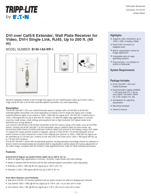
DVI over Cat5/6 Extender, Wall Plate Receiver for Video, DVI-I Single Link, RJ45, Up to 200 ft. (60 m)MODEL NUMBER:B140-1A0-WP-1Receiver wallplate extends a DVI-D single-link signal via one Cat5e/6 patch cable up to 200 ft. with a Tripp Lite B140-002 or B140-004 extender/splitter transmitter unit (sold separately).DescriptionThe B140-1A0-WP-1 DVI over Cat5/6 Extender works in tandem with a B140-002 or B140-004extender/splitter transmitter unit (sold separately) to extend a DVI-D single-link signal over a singleCat5e/6 Ethernet cable. It can extend a 1920 x 1080 (60 Hz) signal up to 150 feet (45.7 meters) and a 1024 x 768 signal (60 Hz) up to 200 feet (61 meters). It's ideal for digital sign applications in schools, churches, trade shows, retail settings and anywhere else a high-resolution DVI signal needs to be delivered over a long distance.Just connect a B140-002 or B140-004 transmitter to the DVI source using a DVI cable, such as the P561-Series. Connect the B140-1A0-WP-1 to the transmitter using a Cat5e/6 cable (for best results, we recommend N202-Series 24 AWG solid-wire Cat5e/6 cable) and connect to the display using a DVI cable. To expand the range and the number of displays, add up to three B140-110 remote repeaters and an active receiver to each channel for a total of four displays per channel. A 1920 x 1080 (60 Hz) signal can be extended up to 125 feet (38.1 meters) to the next unit in the chain and a 1024 x 768 signal (60 Hz) up to 175 feet (53.3 meters).The B140-1A0-WP-1 works with all operating systems. Its plug-and-play technology means no software or drivers need to be downloaded and installed. Built-in equalization control allows for manual adjustment of the video image. Complies with the Federal Trade Agreements Act (TAA) for GSA Schedule purchases.FeaturesExtend DVI-D Signal via Cat5e/6 Patch Cable Up to 200-ft. (61 m)Ideal for digital sign applications in schools, churches, trade shows and retail settingsqWorks in tandem with B140-002 or B140-004 extender/splitter transmitters (sold separately)qExtends a 1920 x 1080 (@ 60 Hz) signal up to 150-ft. (45.7 m)qExtends a 1024 x 768 signal (@ 60 Hz) up to 200-ft. (61 m)qEven More Distance and FlexibilityAdd up to 3 B140-110 remote repeaters and an active receiver for total of 4 displays per channelqCan extend 1920 x 1080 (@ 60 Hz) signal up to 125-ft. (38.1 m) to next unit in chainqCan extend 1024 x 768 (@ 60 Hz) signal up to 175-ft. (53.3 m) to next unit in chainq HighlightsSupports video resolutions up to 1920 x 1080, including 1080pqEasy RJ45 connector onwallplate backqBuilt-in equalization control forimage adjustmentqCompatible with all majoroperating systemsqPlug and play—no software ordrivers to downloadqSystem RequirementsPackage IncludesB140-1A0-WP-1 DVI overCat5/6 ExtenderqExternal power supply w/NEMA 1-15P plug and 5-ft. (1.52 m)cord (Input: 100-240V, 50/60Hz, 0.5A; Output: 5V, 2A)qScrewdriver for adjustingequalizationqMounting hardwareqOwner's manualqSpecificationsConvenient Plug-and-Play Setup No software or drivers requiredq Compatible with all major operating systemsq Easy RJ45 connector on back—no 110 punchdown necessary q HDCP compatibleq Built-in equalization control for image adjustmentqTAA CompliantComplies with the Federal Trade Agreements Act (TAA) for GSA Schedule purchasesq© 2023 Eaton. All Rights Reserved. Eaton is a registered trademark. All other trademarks are the property of their respective owners.。
HDMI连接器专用英语对照

HDMI连接器专用英语对照HDMI连接器专用英语词汇符合HDMI标准的连接器 Connectors to HDMI Standard高清多媒体接口 High Definition Multimedia Interface (HDMI)HDMI A型连接器 HDMI Type A ConnectorHDMI B型连接器 HDMI Type B ConnectorHDMI C型连接器 HDMI Type C Connector一体式数字音频和视频 Digital Audio and Video in one数字电视 Digital Television (DVI)覆盖范围 Scope要求 Rating额定电流 Contact Current Rating温度范围 Temperature Range湿度 Humidity Range大气压力 Atmospheric Pressure控制信息 Preamble数据包 Data Island视频信息 Video Data测试方法和要求 Test Methods and Requirements最小化传输差分信号 Transition Minimized Differential Signaling (TMDS) 高清数字内容保护 High-Bandwidth Digital Content Protection(HDCP) 低电压差分讯号 Low-Voltage Differential Signaling (LVDS)扩展显示标识数据 Extended Display Identification Data(EDID)显示数据信道 Display Data Channel(DDC)全屏蔽提供静电放电保护 Full shielding for electrostatic discharge protection全屏蔽防静电 Full shielding for ESD protection提供无铅工艺 Lead-free process available带或不带面板凸缘 Offered with or without panel flange面板凸缘 Panel flange点对点 Point-to-point分支 Multi-drop热插拔检测 Hot Plug DetectTMDS屏蔽线 TMDS Shield Lines消费电子控制 Consumer Electronics Control(CEC)视频游戏主机 Video game consoles光缆组件 Cable assembliesHDMI连接器专用英语句子高清多媒体接口是将视频和音频合并到单一数字接口的一种规范。
各种线材接口

1. A V Connector --- Audio and video connector2. VGA Connector3. Mini-VGA Connector4. DVI Connector --- Digital Visual Interface5. Mini-DVI Connector6. Micro-DVI Connector7. HDMI --- High-Definition Multimedia Interface8. BNC9. DisplayPort10. Mini DisplayPort11. RCA connector12. S-Video13. Component video & component video connecor/out --- YPbPr14. Composite Video15. VIVO ---- Video In Video Out16. SCART17. D-Terminal18. Digital Flat Panel19. RS232C串口20. Banana connector21. Binding post 接线柱/接线螺母22. D-subminiature23. Speakon connector24. TRS connector25. XLR connector26. VESA Plug and Display27. TV aerial plug28. EVC --- Enhanced Video Connector26. IEEE 1394 interface1. AV Connector --- Audio and video connectorAV接口又称(RCARCA),是指目前一些车载GPS设备,通过自身携带的音、视频端子,连接AV 线路将自身的数据图像声音等,输出到其它显示及视听设备上,如外接显示器或耳机等,接口主要有AV复合端子,S-VIDEO端子,耳机接口等。
DVI1.0测试规范
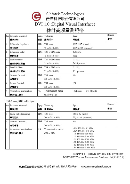
DVI 1.0 (Digital Visual Interface)線材高頻量測規格Item Parameter Measured 量測參數Equip.儀器Test set up量測條件Spec.規格值Remark備註1Differential Impedance 差分阻抗TDR TDR mode75 ps Tr (10-90%)100±Ω10Ω(cable)100Ω±20Ω(assembly)2Differential Delay 差動延遲TDR TDR or TDT mode75 ps Tr (10-90%)5.05ns/mmax3Inter-Pair Skew差分對間延遲差TDR TDR or TDT mode75 ps Tr (10-90%)0.4 T Pixel2424 ps max4Intra-Pair Skew差分對內延遲差TDR TDR or TDT mode75 ps Tr (10-90%)0.25 T Bit151 ps max5Near-end Crosstalk 近端串音TDR TDT mode330 ps Tr (10-90%)4%6Far-end Crosstalk 遠端串音TDR TDT mode330 ps Tr (10-90%)3%7Attenuation/ Insertion Loss 衰減/插入損失NA Transmission mode(S21 or S12)-8 dB/max @1~825MHzDVI-Analog RGB cable Spec.Item Parameter Measured 量測參數Equip.儀器Test set up量測條件Spec.規格值Remark備註1Single-ended Impedance 單端阻抗TDR TDR mode700 ps Tr (10-90%)75±Ω4Ω(cable)75Ω±10% (connector)2Near-end Crosstalk 近端串音TDR TDT mode700 ps Tr (10-90%)3%3Attenuation/ Insertion Loss 衰減/插入損失NA Transmission mode(S21 or S12)-0.14 dB/cable @1 MHz-0.45 dB/cable @10 MHz-1.0 dB/cable @50 MHz-1.5 dB/cable @100 MHz-2.1 dB/cable @200 MHz-3.0 dB/cable @400 MHz-4.3 dB/cable @700 MHz-5.4 dB/cable @1000 MHz參考文件:DDWG- DVI Rev 1.0 ( 1999/04/02 )DDWG-DVI Test and Measurement Guide rev. 1.0( 01/02/25 )桃園縣龜山鄉光明街巷號桃園縣龜山鄉光明街巷號DVI 每對高頻信號線的像素頻寬BW (pixel/sec) 公式如下:BW =H ╳V ╳f ╳〔 〕 1-b1。
各种接口
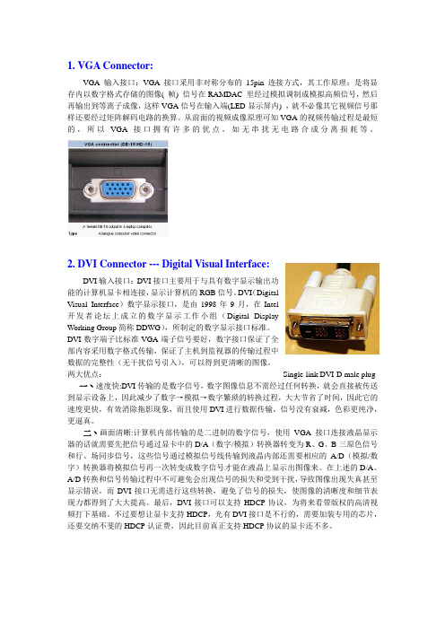
1. VGA Connector:VGA输入接口:VGA 接口采用非对称分布的15pin 连接方式,其工作原理:是将显存内以数字格式存储的图像( 帧) 信号在RAMDAC 里经过模拟调制成模拟高频信号,然后再输出到等离子成像,这样VGA信号在输入端(LED显示屏内) ,就不必像其它视频信号那样还要经过矩阵解码电路的换算。
从前面的视频成像原理可知VGA的视频传输过程是最短的,所以VGA 接口拥有许多的优点,如无串扰无电路合成分离损耗等。
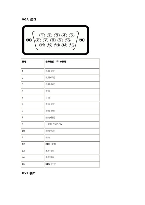
2. DVI Connector --- Digital Visual Interface:DVI输入接口:DVI接口主要用于与具有数字显示输出功能的计算机显卡相连接,显示计算机的RGB信号。
DVI(DigitalVisual Interface)数字显示接口,是由1998年9月,在Intel开发者论坛上成立的数字显示工作小组(Digital DisplayWorking Group简称DDWG),所制定的数字显示接口标准。
DVI数字端子比标准VGA端子信号要好,数字接口保证了全部内容采用数字格式传输,保证了主机到监视器的传输过程中数据的完整性(无干扰信号引入),可以得到更清晰的图像。
两大优点:Single-link DVI-D male plug 一丶速度快:DVI传输的是数字信号,数字图像信息不需经过任何转换,就会直接被传送到显示设备上,因此减少了数字→模拟→数字繁琐的转换过程,大大节省了时间,因此它的速度更快,有效消除拖影现象,而且使用DVI进行数据传输,信号没有衰减,色彩更纯净,更逼真。
二丶画面清晰:计算机内部传输的是二进制的数字信号,使用VGA接口连接液晶显示器的话就需要先把信号通过显卡中的D/A(数字/模拟)转换器转变为R、G、B三原色信号和行、场同步信号,这些信号通过模拟信号线传输到液晶内部还需要相应的A/D(模拟/数字)转换器将模拟信号再一次转变成数字信号才能在液晶上显示出图像来。
DisplayPort和eDP物理层兼容性测试中必须考虑的因素

Getting down to One data lane…
5 Pins1 data
lane
4 data lanes
AUX+/-, HPDConfig1/2
1 low
MyDP speed line
DisplayPort20 Pins
Power, Ground
Power, Ground
HDMI
Something Good is Happening…
MyDP
Standard DisplayPortComputing
eDP
Embedded Systems
Consumer Electronics
Portables
VESA: 200 members strong!
DisplayPort Technology Rollouts
The AUX Channel enables Link setup and maintenance as well as control for testing.
Tx
Driver
Logic
Decode
Main Link
AUX
Hot Plug Detect
Image buffer
EDID
DPCD
Sink
Key Features of DisplayPort
Hot Plug Detect
TransmitterAUX
Receiver (Sink)
AUX ChannelVery robust channel Setup Link/Maintain Link Test Assistance
uPacket BasedNot based on Raster timings Fixed bit rates
Display Port 连接器专业英语句子翻译总结

Display Port 连接器(1)根据 Display Port 标准设计的音频/视频连接器。
这些新产品有助于在计算机和音频可视化组件上呈现高清媒体内容。
Our audio/video connectors designed to the Display Port standard. These new products enable high-definition media content on computers and audio visual components.(2)我们的电缆组件通过了由独立 VESA 授权测试中心开展的全面电池测试,从而获得 Display Port 规范 1.1a 版中定义的全面认证。
Our cable assemblies have achieved full certification as defined in Display Port Specification Version 1.1a, passing a thorough battery of tests performed by an independent VESA authorized test center.(3)这些认证电缆组件基于通过 1 个、2 个或 4 个主链路通道进行的一致数字数据传输,传输速率为每通道 1.62 Gbps(低比特率)或每通道 2.7 Gbps(高比特率)。
These certified cable assemblies are based on consistent transmission of digital data through 1, 2, or 4 main link lanes at the reduced bit rate of 1.62 Gbps per lane or high bit rate of 2.7 Gbps per lane.(4)这将为计算机和消费类应用带来高清晰度的高品质视频。
VGA DVI DP HDMI 接口及DP面板接口定义
VGA 接口针号信号线的15 针针端1视频-红色2视频-绿色3视频-蓝色4接地5自检6接地-红色7接地-绿色8接地-蓝色9计算机5V/3.3V10接地-同步11接地12DDC 数据13水平同步14垂直同步15DDC 时钟DVI 接口针号信号线的24 针针端1 TMDS RX2-2 TMDS RX2+3TMDS 接地4浮点5浮点6DDC 时钟7DDC 数据8浮点9 TMDS RX1-10 TMDS RX1+11TMDS 接地12浮点13浮点14 +5V/+3.3V 电源15自检16热插拔检测17 TMDS RX0-18 TMDS RX0+19TMDS 接地20浮点21浮点22TMDS 接地23TMDS 时钟+24TMDS 时钟- DisplayPort 接口针脚号码已连接信号线的 20 针针侧HDMI 接口针脚号码已连接信号线的19 针针侧1 TMDS 数据2+2 TMDS 数据2 屏蔽线3 TMDS 数据2-4 TMDS 数据1+5 TMDS 数据1 屏蔽线6 TMDS 数据1-7 TMDS 数据0+8 TMDS 数据0屏蔽线9 TMDS 数据0-10 TMDS 时钟信号11 TMDS 时钟信号屏蔽线12 TMDS 时钟信号-13 悬空14 悬空15 DDC 时钟信号(SDA)16 DDC 数据(SDA)17 接地18 +5V 电源19 热插拔检测。
DVI控制台USB接口计算机控制集说明书
q One DVI console controls up to four USB interface computers qDVI-D KVM cable set - Includes two 44-pin Custom KVM cables (4ft & 6ft) to connect up to four computers q Fully compliant with DVI specification (Digital only) q Supports multi-function and wireless mouse/keyboard qAudio enabled – full bass response provides a rich experience for 2.1 channel surround sound systems q Video resolution – up to 1920 x 1200 @60Hz; 1080p Full HD q Auto Scan Mode for monitoring all computers qMultiplatform support – Windows®, Linux®, Mac, FreeBSD and Oracle® Solaris q Console mouse port emulation/bypass feature supports most mouse drivers andmultifunction miceq Hot Pluggable - Add or remove computers for maintenance without powering down the switchq HDCP compliant q Video DynaSync™q Power on Detection - Automatically switches to the next powered-on computer when the other is turned offq Computer selection via front panel pushbuttons, hotkeys, and mouse switching function qUSB 2.0 mouse port can be used for USB hub and USB peripheral sharing q Complete keyboard emulation for error-free booting q Mac/Sun keyboard support and emulation q Firmware Upgradableq Plug & Play - No software installation required4-Port DVI KVM SwitchThis IOGEAR DVI KVM Switch GCS1004 allows users to access up to four computers from a single USB keyboard, USB mouse, and DVI monitor. It supports resolutions up to 1920 x 1200 @60Hz. With IOGEAR's DynaSync™, there is no more delay or change of video resolution when switching between or booting the computers. It also comes equipped with an audio line out and has power on detection – it will automatically switch to the next powered-on computer when the other is turned off. It also allows each computer to access any peripherals connected to the USB 2.0 port and with its audio enabled, users can listen to the audio output of each computer on one set of speakers.The setup is quick and easy; users just need to plug the cables into their appropriate ports. There is no software to configure. Since GCS1004 intercepts keyboard input directly, it supports multiple computing platforms (PC x86 / x64, Macintosh PowerPC, and Oracle® Solaris Microsystems Sparc).There are three convenient methods users can use to access the computers: port selection push buttons located on the unit's front panel; hotkey combinations entered from the keyboard;and mouse port-switching by simply double-clicking on the scroll wheel of a USB mouse to change the ports.4-Port USB DVI KVM SwitchGCS1004SpecificationsqConsole:q 1 DVI displayq 1 set of USB keyboard and mouseq Speakers (optional)qq Computers:q 1 DVI Portq 2 USB Portsq Audio ports (optional)q Computers with sound supportqq Operating Systems:q Windows® XP, Windows Vista®,Windows® 7, Windows® 8,Windows® 8.1q Mac OS 9 to 10.xq Oracle® Solarisq Linux®, Unix and other USBsupported systems**Additional drivers and support may beneededProduct Requirementsq 1 x GCS1004 4-Port USB DVI KVMSwitchq 1 x 4ft 44-pin Custom KVM Cable setq 1 x 6ft 44-pin Custom KVM Cable setq 1 x Power Adapterq 1 x User Manualq 1 x Warranty CardPackage ContentsFunction GCS1004Dimensions GCS1004Unit DimensionsHeight 1.06" (2.69cm)Depth 3.25" (8.26cm)Length7.88" (20.02cm)Unit Package DimensionsWidth11.25" (28.58cm)Height 6.94" (17.63cm)Depth 4.00" (10.16cm)Master CartonWidth12.81" (32.54cm)Height15.06" (38.18cm)Depth11.81" (30.00cm)Master Carton Qty.6WeightMaster Carton Wt.24.50lbs (11.11kg)Unit Pack Wt. 3.85lbs (1.75kg)Unit Wt. 1.10lbs (0.499kg)19641 Da Vinci, Foothill Ranch, CA 92610 GCS1004© 2014 IOGEAR®IOGEAR, the IOGEAR logo, are trademarks or registered trademarks of IOGEAR. Microsoft and Windows are registered trademarks of Microsoft Corporation. All other brand and product names are trademarks or registered trademarks of their respective holders. IOGEAR makes no warranty of any kind with regards to the information presented in this document. All information furnished here is for informational purposes only and is subject to change without notice. IOGEAR assumes no responsibility for any inaccuracies or errors that may appear in this document.4-Port USB DVI KVM Switch。
DVI协会规范
视频各种接口解释

视频各种接口解释HDMI(高清晰多媒体接口)是惟一一个支持工业、非压缩、全数字视频和音频的接口S端子指能输入或输出Y信号和C信号的接口,可以提高图像清晰度A V端子指多组音频(Audio)/视频video输入/输出接口VGA接口就是显卡上输出模拟信号的接口分量视频接口你从字面上理解一下就是综合接口的集合TV接口电视接口DVI接口一样高清晰的视频接口用于液晶显示器或平板电视等等D-Sub接口和VGA接口是一样的含义YPbPr接口业界推崇的最为标准的高清晰数字视频接口。
能将模拟的Y、PB、PR信号分开,使用三条线缆来独立传输RF接口每接触过大概是无线技术了解没?不用太深究端口的含义!实际上他们都是视频输出端口只是不同类型罢了在新推出的一些电脑显示卡上,我们可以发现形状和规格与熟悉的VGA完全不同的白色端口,其实就是未来的数字接口DVI。
DVI是Digital Visual Interface 的缩写,全称是数字视频介面。
DVI是个非常重要的数字视频新标准,这个标准是由数字视频工作组(Digital Display Working Group,简称DDWG)推出的,其中的主要成员包括电脑和数字视频业界的领导者Intel和Silicon Image。
传统的视频接口都是模拟方式的复合视频(Video)、S视频(S-Video)、色差(Y/Cr/Cb)和VGA等形态,对于目前日益增多的DVD、PC、HDTV等数字视频信号传输来说,必然会带来数模转换过程的损失和传输失真,也不利于发挥数字电视和DLP、LCD等点阵显示设备的优势,DDWG从成立开始就致力于显示设备的数字化,DVI就是由DDWG所发展的数字视频传输介面。
DVI的数据传输采用TMDS协议,由Silicon Image所开发,业界也称之为Panel Link,主要这种传输协议当初的目的就是针对各种新型的平面数字显示新器件而设计。
正因为如此,Silicon Image 的IC芯片也更为常见。
光学术语中英文对照
透镜系列术语中英文对照单透镜 Simple (Single) Lenses球透镜 Ball Lenses歪像透镜 Anamorphic Lenses圆锥透镜 Conical Lenses柱状透镜,环形透镜 Cylindrical & Toroidal Lenses非球面透镜 Aspheric Lenses反射折射透镜 Catadioptric Lenses绕射极限透镜 Diffraction-Limited LensesGRIN透镜 GRIN Lenses (Graduated Refractive Index Rod)微小透镜阵列 Micro Lens Arrays准直透镜 Collimator Lenses聚光透镜 Condenser Lenses多影像透镜 Multiple Image Lenses傅利叶透镜 Fourier Lenses菲涅尔透镜 Fresnel Lenses替续透镜 Relay Lenses大口径透镜(直径150mm以上) Large Aperture Lenses (150mm) 复合透镜 Complex Lenses红外线透镜 Infrared Lenses紫外线透镜 Ultraviolet Lenses激光透镜 Laser Lenses望远镜对物镜 Telescope Objectives Lenses显微镜对物镜 Microscope Objectives Lenses接目镜 Eyepieces Lenses向场透镜 Field Lenses望远镜头 Telephoto Lenses广角镜头 Wide Angle Lenses可变焦伸缩镜头 Variable Focal Length Zoom LensesCCTV镜头 CCTV Lenses影印机镜头 Copy Machine Lenses传真机镜头 Facsimile Lenses条码扫描器镜头 Bar Code Scanner Lenses影像扫描器镜头 Image Scanner Lenses光碟机读取头透镜 Pick-up Head LensesAPS相机镜头 APS Camera Lenses数位相机镜头 Digital Still Camera Lenses液晶投影机镜头 Liquid Crystal Projector Lenses镜面系列术语中英文对照平面镜 Flat Mirrors球面凹面镜,球面凸面镜 Spherical Concave and Convex Mirrors 抛物面镜,椭圆面镜 Off-Axis Paraboloids and Ellipsoids Mirrors 非球面镜 Aspheric Mirrors多面镜 Polygonal Mirrors热镜 Hot Mirrors冷镜 Cold Mirrors玻璃,玻璃/陶瓷面镜 Glass and Glass-Ceramic Mirrors双色向面镜 Dichroic Mirror金属面镜 Metal Mirrors多层面镜 Multilayer Mirrors半涂银面镜 Half-Silvered Mirrors激光面镜 Laser Mirrors天文用面镜 Astronomical Mirrors棱镜系列术语中英文对照Nicol棱镜 Nicol PrismsGlan-Thomson棱镜 Glan-Thomson PrismsWollaston棱镜 Wollaston PrismsRochon棱镜 Rochon Prisms直角棱镜 Right-Angle; Rectangular Prisms五面棱镜 Pentagonal Prisms脊角棱镜 Roof Prisms双棱镜 Biprisms直视棱镜 Direct Vision Prisms微小棱镜 Micro Prisms滤光镜系列术语中英文对照尖锐滤光镜 Sharp Cut (off) Filters色温变换滤光镜,日光滤光镜 Colour Conversion/Daylight Filters 干涉滤光镜 Interference Filters中性密度滤光镜 Neutral Density Filters空间/光学匹配滤光镜 Spatial/Optical Matched Filters双色向滤光镜 Dichroic Filters偏光滤光镜 Polarizing Filters排除频带滤光镜 Rejection Band Filters可调式滤光镜 Turnable Filter超窄频滤光镜 Ultra Narrowband Filters色吸收滤光镜 Absorption Filters红外吸收/反射滤光镜 Infrared Absorbing/Reflecting Filters红外透过滤光镜 Infrared Transmitting Filters紫外吸收滤光镜 Ultraviolet Absorbing Filters紫外透过滤光镜 Ultraviolet Transmitting Filters针孔滤光镜 Pinhole Filters有色玻璃滤光镜 Colored-Glass Filters塑胶滤光镜 Plastic Filters照像用滤光镜 Photographic Filters全像滤光镜 Holographic Filters微小干涉滤光镜 Micro Interference Filters光学词汇Iris – aperture stop虹膜孔径光珊retina视网膜Color Blind 色盲weak color 色弱Myopia – near-sighted 近视Sensitivity to Light感光灵敏度boost推进lag behind落后于Hyperopic – far-sighted 远视Dynamic Range 动态范围critical fusion frequency 临界融合频率CFF临界闪变频率visual sensation视觉Chromaticity Diagram色度图Color Temperature色温HSV Model色彩模型(hue色度saturation饱和度value纯度CIE Model 相干红外能量模式Complementary Colors补色Bar Pattern条状图形Heat body 热稠化approximate近似violet紫罗兰Body Curve人体曲线Color Gamut色阶adjacent邻近的normal illumination法线照明Primary colors红黄蓝三原色Color saturation色饱和度Color Triangle颜色三角Color Notation颜色数标法Color Difference色差TV Signal Processing电视信号处理Gamma Correction图像灰度校正Conversion Tables换算表out of balance失衡wobble摇晃back and forth前后clear (white) panel白光板vibrant震动fuzzy失真quantum leap量子越迁SVGA (800x600)derive from起源自culprit犯人render呈递inhibit抑制,约束stride大幅前进blemish污点obstruction障碍物scratch刮伤substance物质实质主旨residue杂质criteria标准parameter参数adjacent邻近的接近的asynchrony异步cluster串群mutually互助得algorithm运算法则Chromatic Aberrations色差Fovea小凹Visual Acuity视觉灵敏度Contrast Sensitivity对比灵敏度Temporal (time) Response反应时间rendition表演,翻译animation活泼又生气ghost重影Parallax视差deficient缺乏的不足的Display panel显示板NG.( Narrow Gauge)窄轨距dichroic mirror二色性的双色性的Brewster Angle布鲁斯特角Polarized Light极化光Internal reflection内反射Birefringence 双折射Extinction Ratio 消光系数Misalignment 未对准Quarter Waveplates四分之一波片blemish污点瑕疵Geometric几何学的ripple波纹capacitor电容器parallel平行的他tantalum钽(金属元素) exsiccate使干燥exsiccate油管,软膏furnace炉子镕炉electrolytic电解的,由电解产生的module模数analog类似物out of the way不恰当pincushion针垫拉lateral侧面得rectangle长方形fixture固定设备control kit工具箱DVI connector DVI数局线Vertical垂直的horizontal 水平的interlace隔行扫描mullion竖框直楞sawtooth锯齿toggle套索钉keypad数字按键键盘tangential切线diagnostic tool诊断工具sagittal direction径向的cursor position光标位置ray aberration光线相差weighting factor权种因子variables变量for now暂时,目前.眼下check box复选框Airy disk艾里斑exit pupil出[射光]瞳optical path difference光称差with respect to关于diffraction limited衍射极限wavefront aberration波阵面相差spherical aberration球面象差paraxial focus傍轴焦点chromatic aberration象差local coordinate system局部坐标系统coordinate system坐标系orthogonal直角得,正交的conic sections圆锥截面account for解决,得分parabolic reflector拋物面反射镜radius of curvature曲率半径spherical mirror球面镜geometrical aberration几何相差incident radiation入射辐射global coordinate总体坐标in terms of根据按照reflected beam反射束FYI=for your information供参考Constructive interference相长干涉phase difference相差achromatic singlet消色差透镜Interferometer干涉仪boundary constraint边界约束,池壁效应radii半径Zoom lenses变焦透镜Beam splitters分束器discrete不连续的,分离的objective/eye lens物镜/目镜mainframe主机rudimentary根本的,未发展的photographic照相得摄影得taxing繁重的,费力得algebra代数学trigonometry三角学geometry几何学calculus微积分学philosophy哲学lagrange invariant拉格朗日不变量spherical球的field information场信息Standard Lens标准透镜Refracting Surface折射面astigmatism散光HDTV高清晰度电视DLV ( Digital Light Valve)数码光路真空管,简称数字光阀diffraction grating衍射光珊field angle张角paraxial ray trace equations近轴光线轨迹方称back focal length后焦距principal plane主平面vertex顶点,最高点astigmatism散光,因偏差而造成的曲解或错判medial中间的,平均的variance不一致conic圆锥的,二次曲线field of view视野collimator瞄准仪convolution回旋.盘旋,卷积fuzzy失真,模糊aberrated异常的asymmetry不对称得indicative可表示得parabolic拋物线得suffice足够,使满足specification规格,说明书straightforward易懂的,直接了当的solidify凝固,巩固.Constraints 约束,限制metrology度量衡field coverage视场,视野dictate口述, 口授, 使听写, 指令, 指示, 命令, 规定irradiance发光, 光辉,辐照度aerial空气得,空中得halide卤化物的monochromatic单色的,单频的polychromatic多色的aspherical非球面的spherical球面的alignment列队,结盟power(透镜)放大率equiconvergence 同等收敛EFL(effective focal length)有效焦距workhorse广为应用的设备biconvex两面凸的global optimization整体最优化concave凹得,凹面得cylindrical圆柱得solid model实体模型Modulation Transfer Function调制传递函数in the heat of在最激烈的时候protocol协议,规定triplet三重态sanity心智健全zinc锌,涂锌的selenide 硒化物,硒醚miscellaneous各色各样混在一起, 混杂的, 多才多艺的versus与...相对polynomial多项式的coefficient系数explicit function显函数distinct清楚的,截然不同的emanate散发, 发出, 发源rudimentary根本的,未发展的intersection角差点PRTE=paraxial ray trace equation旁轴光线轨迹方程achromats 消色差透镜cardinal points基本方位separations分色片dashed虚线blow up 放大overlay覆盖,覆盖图multiplayer 多层的humidity 湿度float glass 浮法玻璃square one 出发点,端点square up to 准备开打,坚决地面对reflecting telescope 反射式望远镜diagnostic tools诊断工具Layout plots规划图Modulation transfer function调制转换功能FFT快速傅里叶变换Point spread function点传播功能wavelength波长angle角度absorption吸收system aperture系统孔径lens units透镜单位wavelength range波长范围singlet lens单业透镜spectrum光谱diffraction grating衍射光栅asphere半球的LDE=Lens data editor Surface radius of curvature表面曲率半径surface thickness表面厚度material type材料种类semi-diameter半径focal length焦距aperture type孔径类型aperture value孔径值field of view视场microns微米F, d, and C= blue hydrogen, yellow helium, red hydrogen lines, primary wavelength主波长sequential mode连续模式object surface物表面The front surface of the lens透镜的前表面stop光阑The back surface of the lens透镜的后表面The image surface像表面symmetric相对称的biconvex两面凸的The curvature is positive if the center of curvature of the surface is to the right of the vertex. It is negative if the center of curvature is to the left of the vertex.如果曲率中心在最高点的右边,曲率值为正,如果曲率中心在最高点的左边,则曲率为负image plane像平面Ray Aberration光线相差tangential direction切线方向sagittal direction 径向paraxial focus旁轴的Marginal边缘的spherical aberration球面像差Optimization Setup最优化调整variable变量mathematical sense数学角度MFE= Merit Function Editor, Adding constraints增加约束focal length焦矩长度operand操作数the effective focal length有效焦矩primary wavelength主波长initiate开始spot diagram位图表Airy disk 艾里斑axial chromatic aberration轴向色差with respect to关于至于exit pupil出射光瞳OPD=optical path difference光学路径差diffraction limited衍射极限chromatic aberration色差chromatic focal shift色焦距变换paraxial focus傍轴焦点axial spherical aberration轴向球差(longitudinal spherical aberration 纵向球差:沿光轴方向度量的球差)lateral spherical aberration垂轴球差(在过近轴光线像点A‵的垂轴平面内度量的球差)coma、comatic aberration彗差meridional coma子午彗差sagittal coma弧矢彗差astigmatism像散local coordinate system 本地坐标系统meridional curvature of field子午场曲sagittal curvature of field弧矢场曲decentered lens偏轴透镜orthogonal直角的垂直的conic section圆锥截面account for说明,占有,得分stigmatic optical system无散光的光学系统Newtonian telescope牛顿望远镜parabolic reflector抛物面镜foci焦距chromatic aberration,色差superpose重迭parabola抛物线spherical mirror球面镜RMS=Root Mean Square均方根wavefront波阵面spot size光点直径Gaussian quadrature高斯积分rectangular array矩阵列grid size磨粒度PSF=Point Spread Function点扩散函数FFT=Fast Fourier Transform Algorithm快速傅里叶变换Cross Section横截面Obscurations昏暗local coordinates局部坐标系统vignette把…印为虚光照Arrow key键盘上的箭头键refractive折射reflective反射in phase同相的协调的Ray tracing光线追迹diffraction principles衍射原理order effect式样提出的顺序效果energy distribution 能量分配Constructive interference相长干涉dispersive色散的Binary optics二元光学phase advance相位提前achromatic single消色差单透镜diffractive parameter衍射参数Zoom lenses变焦透镜Athermalized lenses绝热透镜Interferometers干涉计Beam splitter分束器Switchable component systems可开关组件系统common application通用symmetry 对称boundary constraint边界约束multi-configuration (MC) MC Editor(MCE) perturbation动乱,动摇index accuracy折射率准确性index homogeneity折射率同种性index distribution折射率分配abbe number 离差数Residual剩余的Establishing tolerances建立容差figure of merit 质量因子tolerance criteria公差标准Modulation Transfer Function (MTF)调制传递函数boresight视轴,瞄准线Monte Carlo蒙特卡洛Tolerance operands误差操作数conic constant ]MC1"{_qT .ueg g圆锥常数astigmatic aberration像散误差Mechanical tilt机械倾斜,机械倾角Tolerance Data Editor (TDE)公差资料编辑器compensator补偿棱镜estimated system performance预估了的系统性能iteratively反复的,重迭的statistical dependence统计相关性sequential ray trace model 连续光线追迹模型imbed埋葬,埋入multiple多样的,多重的,若干的Non-Sequential Components不连续的组件Corner cube角隅棱镜,三面直角透镜Sensitivity Analysis灵敏度分析Faceted reflector有小面的反射镜emit发射,发出nest嵌套overlap交迭outer lens外透镜brute force强力seidel像差系数aspect ratio长宽比MRA边缘光线角MRH 边缘光线高度asynchronous不同时的,异步Apodization factor变迹因子hexapolar六角形dithered高频脉冲衍射调制传递函数(DMTF),衍射实部传递函数(DRTF),衍射虚部传递函数(DITF),衍射相位传递函数(DPTF),方波传递函数(DSWM)logarithmic对数的parity奇偶% Uc,I e ,17]3NnoClongitudinal aberrations 纵向像差赛得系数: 球差(SPHA,SI),彗差(COMA,S2),像散(ASTI,S3),场曲(FCUR,S4),畸变(DIST,S5),轴向色差(CLA,CL)和横向色差(CTR,CT).横向像差系数:横向球差(TSPH),横向弧矢彗差(TSCO),横向子午彗差(TTCO),横向弧矢场曲(TSFC),横向子午场曲(TTFC),横向畸变(TDIS)横向轴上色差(TLAC)。
HDMI接口与DVI接口
DVI接口详解DVI全称为Digital Visual Interface,是1999年由Silicon Image、Intel(英特尔)、Compaq(康柏)、IBM、HP(惠普)、NEC、Fujitsu(富士通)等公司一起组成的数字显示工作组DDWG(Digital Display Working Group)推出的接口标准,其外观是一个24针的接插件。
显示设备采纳DVI接口具有要紧有以下两大优势:一、速度快:DVI传输的是数字信号,数字图像信息不需通过任何转换,就会直接被传送到显示设备上,因此减少了数字→模拟→数字繁琐的转换进程,大大节省了时刻,因此它的速度更快,有效排除拖影现象,而且利用DVI进行数据传输,信号没有衰减,色彩更纯净,更传神。
二、画面清楚:运算机内部传输的是二进制的数字信号,利用VGA接口连接液晶显示器的话就需要先把信号通过显卡中的D/A(数字/模拟)转换器转变成R、G、B三原色信号和行、场同步信号,这些信号通过模拟信号线传输到液晶内部还需要相应的A/D(模拟/数字)转换器将模拟信号再一次转变成数字信号才能在液晶上显示出图像来。
在上述的D/A、A/D转换和信号传输进程中不可幸免会显现信号的损失和受到干扰,致使图像显现失真乃至显示错误,而DVI接口无需进行这些转换,幸免了信号的损失,使图像的清楚度和细节表现力都取得了大大提高。
区分不同DVI标准DVI接口有多种规格,分为DVI-A、DVI-D和DVI-I,它是以Silicon Image公司的PanalLink 接口技术为基础,基于TMDS(Transition Minimized Differential Signaling,最小化传输差分信号)电子协议作为大体电气连接。
TMDS是一种微分信号机制,能够将象素数据编码,并通过串行连接传递。
显卡产生的数字信号由发送器依照TMDS协议编码后通过TMDS通道发送给接收器,通过解码送给数字显示设备。
DVI连接器专用英语对照
DVI连接器专用英语对照DVI连接器专用英语词组数字显示工作组 Digital Display Working Group(DDWG)产品 Product浏览产品 View Product行业和解决方案 Industries & solutionDVI连接器 DVI ReceptacleDVI母端连接器 DVI Receptacle Connector机顶盒 Set-top boxes高端电视/显示器 High-end TVs/ Monitors高清视频High-resolution Video视频图形应用 Video graphics application工作站 Workstations个人计算机 Personal computer零售商业设备 Retail business equipment游戏系统和设备 Game systems and devices电磁干扰 Electromagnetic Interference(EMI)专为实现可靠的高性能而设计 Digital visual interface engineered for reliable high performanceDVI连接器专用英语句子我们的数字视频接口连接器旨在满足数字显示工作组的DVI规范,同时提供易于使用的即插即用连接功能以及可降低电磁干扰和串扰的串行数字数据传输功能。
Our DVI connectors are designed to meet the Digital Display Working Group’s DVI specification, while also providing plug-and-playconnectivity for ease of use and serial digital data transmission for reduced electromagnetic interference and crosstalk.我们的高清视频应用可满足PC行业各方面的要求,允许采用单一显示器接口规范。
DVI CABLE 说明
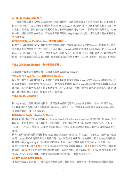
2. Digital Display Cable 简介高速传输及数字化是信息及通讯产品共同的趋势,因此在显示器及其屏幕的应用上,为了确保不同显示器(如CRT,LCD等)及不同的屏幕应用(如VGA,XGA或HDTV等)可以在不同的主机( Host ) 平台上执行其功能,目前有一些非营利单位致力于标准规格的制定与推广。
有的着眼于纯数字化,有的维持以前模拟显示器的兼容性,有的加上即插即用线( Plug & Play )的功能。
以下是几个现在著名的单位与其规格。
DDWG-DVI( Digital Visual Interface –数字视讯接口)以数字显示器的需求为主,但也提供之前模拟阴极射线管屏幕( Analog CRT Monitor )的兼容性。
所以其连接器亦分为纯数字( DVI- DOC : Digital Only Connector)或数字/模拟兼具的( DVI- CC : Combined Connector) 连接器。
不过DVI并没有提供其它输出入I/O,如USB,IEEE-1394a的功能。
此标准亦考虑到了数字显示器长远的发展。
因此,连接器的定义已含括了两个T.M.D.S 连结的( two links ) 功能。
VESA-DFP( Digital Flat Panel - 数字平面显示器)主要着眼于纯数字平面显示器。
使用的连接器为标准的MDR 20。
VESA-P&D( Plug & Display –即插即用与显示器)除了制订数字显示器的需求外,也提供之前模拟阴极射线管屏幕( Analog CRT Monitor )的兼容性。
所以其连接器可分为纯数字( P&D-Digital ),数字/模拟兼具的( P&D- Analog/Digital)或纯模拟(P&D-Analog)连接器。
其中的数字视讯之传输技术是使用一对TMDS link,当然,也为了提供更多输出入( I/O )的功能,此标准也加入了USB 及IEEE-1394a 的功能。
FDX-2000单链接DVI-D信号扩展器说明书
3. Using compatible cables, connect the DVI, mouse, keyboard , and sound from the PC to the FDX-TX2000.
4. Connect and run 2 SC fiber from the FDX-TX2000 to the FDX-RX2000’s location.
audio up to 1400 feet using multimode fiber optics.
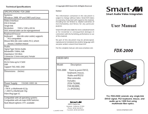
Introduction
The FDX-2000 extends any DVI-D signal, keyboard, mouse and audio up to 1400 feet with fiber cable.
Installing and preparing the
Fiber
1. Fiber used, SC type 2. 62.5μ fiber optic cable , 800 ft. 3. 1400μ fiber optic cable, 1,4Mouse Mini din color coded, PS/2, wheel
mouse, 5-button mouse Audio Signal Type Stereo Audio Bandwidth 15MHz, 0dB Impedance 100 Ohm Connector 3.5mm mini jack, Female RS232 RS232 Data up to 57,600 DB9 Support TXD, RXD, GND
Dimensions (Inches)
- 1、下载文档前请自行甄别文档内容的完整性,平台不提供额外的编辑、内容补充、找答案等附加服务。
- 2、"仅部分预览"的文档,不可在线预览部分如存在完整性等问题,可反馈申请退款(可完整预览的文档不适用该条件!)。
- 3、如文档侵犯您的权益,请联系客服反馈,我们会尽快为您处理(人工客服工作时间:9:00-18:30)。
DVI ConnectorSpecification Foxconn International6125 Phyllis Drive Phone: (714) 890-8628 Cypress, CA 90630Fax: (714) 892-8668 PERFORMANCE CHARACTERISTICS OFDIGITAL VISUAL INTERFACE (DVI)CONNECTORS AND CABLE ASSEMBLIESRelease AJune 27, 2000SummaryThis document defines the performance characteristics of Foxconn DVI plugs, receptacles and cable assemblies.PrefaceIntellectual PropertyCopyright © 2000 Foxconn International. All rights reserved.While every precaution has been taken in the preparation of this specification, Foxconn International and its contributors assume no responsibility for errors or omissions, and make no warranties, expressed or implied, of functionality or suitability for any purpose.TrademarksAll trademarks used within this document are the property of their respective owners. VESA, EDDC and EDID are trademarks of the Video Electronics Standard Association. I2C is a trademark owned by Philips. DVI is a trademark of the Digital Display Working Group.Support for this SpecificationClarifications and application notes to support this specification may be written. To obtain the latest standard and any support documentation, contact Foxconn.If you have a product, which incorporates DVI, Foxconn can assist you with any clarification you may require. All comments or reported errors should be submitted in writing to Foxconn using one of the following methods.•Fax:+1-714-892-8668, direct this note to DVI Technical Support at Foxconn•e-mail:don.chambers@•mail:DVI Technical SupportFoxconn International6125 Phyllis DriveCypress, CA 90630Revision HistoryR elease Draft June 6, 2000 I nitial draftI nitial Release June 27, 2000 I nitial releaseT able of ContentsREVISION HISTORY (3)1.OVERVIEW (6)1.1S UMMARY (6)1.2B ACKGROUND (6)1.3R EFERENCE D OCUMENTS (6)1.4P ART N UMBER B REAKDOWN (6)1.5T YPES OF C ONNECTORS (6)1.5.1DVI Family of Connectors (7)1.5.2DVI-I per DDWG (7)1.5.3DVI-I per ATX (7)1.5.4DVI-I Vertical (7)1.5.5DVI-D per DDWG (8)1.5.6DVI-D per ATX (8)1.5.7DVI-D Vertical (8)1.6F EMALE S CREWLOCKS (8)2.MECHANICAL DETAILS (9)2.1DDWG L AYOUT DVI-I R ECEPTACLE (9)2.2ATX L AYOUT DVI-I R ECEPTACLE (9)2.3V ERTICAL M OUNT DVI-I R ECEPTACLE (10)2.4DDWG L AYOUT DVI-D R ECEPTACLE (11)2.5ATX L AYOUT DVI-D R ECEPTACLE (11)2.6V ERTICAL M OUNTING DVI-D R ECEPTACLE (12)2.7R ECOMMENDED PCB L AYOUTS (13)2.7.1PCB Layout for DVI-D per DDWG (13)2.7.2PCB Layout for DVI-D per ATX (13)2.7.3PCB Layout for DVI-D Vertical Mounting (14)2.7.4PCB Layout for DVI-I per DDWG (15)2.7.5PCB Layout for DVI-I per ATX (15)2.7.6PCB Layout for DVI-I Vertical Mounting (16)3.REQUIREMENTS (17)3.1S TANDARD P ART D OCUMENTS (17)3.2M ATERIALS (17)3.2.1Metals (17)3.2.2Components (17)3.3D ESIGN AND C ONSTRUCTION (17)3.4S IGNAL A SSIGNMENTS (17)Digital Pin Assignments (18)Combined Digital and Analog Pin Assignments (18)4.QUALITY ASSURANCE PROVISIONS (19)4.1M ECHANICAL P ERFORMANCE (19)4.2E LECTRICAL P ERFORMANCE (20)4.3E NVIRONMENTAL P ERFORMANCE (23)4.4T EST S EQUENCES (24)4.4.1Group I: Mated Environment (24)4.4.2Group II: Mated Mechanical (25)4.4.3Group III: Mechanical Mate/Unmate Forces (26)4.4.4Group IV: Insulator Integrity (27)4.4.5Group V: Cable Flexing (28)4.4.6Group VI: Electrostatic Discharge (28)5.APPENDIX A – EYE PATTERN TEST DATA (29)List of FiguresFigure 1-1 Receptacle Part Number Breakdown (6)Figure 5-2 Eye Pattern at 1.25 GHz (29)Figure 5-3 Eye Pattern at 1.65 GHz (30)Figure 5-4 Eye Pattern at 1.85 GHz (31)Figure 5-5 Eye Pattern at 2.20 GHz (32)1.OVERVIEW1.1SummaryT he Digital Visual Interface (DVI) described in this document, is an interface structure providing a high-speed digital connection for visual data types, with optional variants. To support legacy display transducer technology, analog signals may optionally be included in the same connector. Plug and play features are supported through the implementation of VESA EDID and VESA EDDC standards. Hot plug detection is provided to ensure industry compliance.1.2BackgroundT he DVI specification was created to ensure that a high-speed digital interface standard existed to transfer video data in a lossless digital domain and is licensed under the terms and conditions of the Digital Display Working Group, Digital Visual Interface Specification Revision 1.0 Adopter’s Agreement.1.3Reference DocumentsN ote: Versions identified here are current, but users of this standard are advised to ensure they have the latest versions of referenced standards and documents.•DDWG Digital Visual Interface, Revision 1.0, April 2, 1999•DDWG, Digital Visual Interface Specification Revision 1.0 Adopter’s Agreement.•ANSI/EIA Electrical Connector/Socket Test Procedures Including Environmental Classifications, Revision C, December 1994 (EIA-364-C)•VESA Enhanced Display Data Channel, Version 1, September 2, 1999 (EDDC)•VESA Enhanced Extended Display Identification Data Standard, Release A, September 2, 1999 (EEDID)1.4Part Number BreakdownThe DVI connector is available in a multiplicity of combinations, which will be detailed in this specification. Due to the difficulty in properly terminating the DVI plug, Foxconn does not sell plugs. For part numbers of DVI cable assemblies with plugs, please contact Foxconn sales. The Foxconn part number for ordering DVI receptacles is as follows:Figure 1-1 Receptacle Part Number Breakdown1.5Types of ConnectorsThe standardization effort leading to the DVI specification created two different interfaces, one that is digital only, known as DVI-D, and one that combines both analog and digital known as DVI-I.1.5.1 DVI Family of ConnectorsDVI compliant host systems may provide either a digital only interface or a combined analog and digital interface.The system-side (host) connector distinguishes the system capabilities. The two defined connectors have the same physical outer dimensions. In each case the digital signals are present, allowing a monitor with a digital interface to attach directly to either system connector. Because the digital only receptacle does not have sockets for the analog pins of an analog monitor, the plug of an analog monitor will not mate with the digital only system.The DVI-D plug connects to the digital only DVI-D receptacle and the DVI-I receptacle. The DVI-I plug only connects to the DVI-I receptacle. The relationship between the plug connectors and the corresponding host receptacles is shown below:Monitor: Plug Host: Receptacle DVI-I DVI-IAnalog video interfaceDVI-D DVI-DDigital video interface Digital Only HostThe DVI family of connectors uses physical features to ensure that displays using a given interface type (either analog or digital) will not be connected to hosts that cannot support them and will connect to interfaces.Analog interface monitors will use the DVI-I, which provides both analog and digital support.In order to accommodate the requirements of the ATX specification a variation of the PCB layout is also provided.The ATX layouts do not have the plastic locating posts and the grounding clip is a latching type that is designed to retain the connector into the board prior to soldering. For illustration of installation impact, compare the PCB patterns of DDWG versus the ATX, Section 2.7.1 versus 2.7.2 and 2.7.4 versus 2.7.5.1.5.2 DVI-I per DDWGThe combined digital and analog capable, right angle mounting receptacle with the PCB footprint as defined in the DDWG specification, is shown in Section 2.1; the associated PCB layout is shown in Section 2.7.4. Example of Foxconn part number is QH11121-CP0.1.5.3 DVI-I per ATXThe combined digital and analog capable, right angle mounting receptacle with the PCB footprint as modified in accordance with the design parameters of the ATX specification, is shown in Section 2.2; the associated PCB layout is shown in Section 2.7.5. Example of Foxconn part number is QH11121-CB0.1.5.4 DVI-I VerticalThe combined digital and analog capable, vertical mounting receptacle with a PCB footprint similar to that defined in the DDWG specification, is shown in Section 2.3; the associated PCB layout is shown in Section 2.7.6. Example of Foxconn part number is QH11121-CW0.1.5.5DVI-D per DDWGThe basic, digital only, right angle mounting receptacle with the PCB footprint as defined in the DDWG specification, is shown in Section 2.4; the associated PCB layout is shown in Section 2.7.1. Example of Foxconn part number is QH11121-DP0.1.5.6DVI-D per ATXThe basic, digital only, right angle mounting receptacle with the PCB footprint as modified in accordance with the design parameters of the ATX specification, is shown in Section 2.5; the associated PCB layout is shown in Section 2.7.2. Example of Foxconn part number is QH11121-DB0.1.5.7DVI-D VerticalThe basic, digital only, vertical mounting receptacle with a PCB footprint similar to that defined in the DDWG specification, is shown in Section 2.6; the associated PCB layout is shown in Section 2.7.3. Example of Foxconn part number is QH11121-DW0.1.6Female ScrewlocksTo facilitate the many needs of Foxconn customers, DVI connectors are available without female screwlocks or with them installed in the connector. Determination of whether or not to have female screwlock supplied with the connector is specified by the last digit of the part number (see Figure 1-1). Female screwlocks may be ordered as a loose piece item, P/N 062-0004-049. Contact your Foxconn/Hon Hai sales person to determine availability.2.Mechanical Details2.1DDWG Layout DVI-I ReceptacleT he DVI-I receptacle is shown with the female screw locks installed.2.2ATX Layout DVI-I ReceptacleShown without female screwlocks installed.2.3Vertical Mount DVI-I ReceptacleShown with female screwlocks installed.2.4DDWG Layout DVI-D ReceptacleShown without female screwlocks installed.2.5ATX Layout DVI-D ReceptacleShown without female screwlocks installed.2.6Vertical Mounting DVI-D ReceptacleShown without female screwlocks installed.2.7Recommended PCB LayoutsOn the following pages are the recommended PCB layouts for each configuration of Foxconn DVI receptacle.2.7.1PCB Layout for DVI-D per DDWGThis layout is required for Foxconn P/N QH1112*-DP*2.7.2PCB Layout for DVI-D per ATXThis layout is required for Foxconn P/N QH1112*-DB*2.7.3PCB Layout for DVI-D Vertical Mounting This layout is required for Foxconn P/N QH1112*-DW*2.7.4PCB Layout for DVI-I per DDWG This layout is required for Foxconn P/N QH1112*-CP*2.7.5PCB Layout for DVI-I per ATXThis layout is required for Foxconn P/N QH1112*-CB*2.7.6PCB Layout for DVI-I Vertical Mounting This layout is required for Foxconn P/N QH1112*-CW*3.Requirements3.1Standard Part DocumentsThe individual item requirements shall be as specified herein. In event of a conflict between this specification and the specified test requirement document, this specification shall govern.3.2Materials3.2.1MetalsMetals shall be plated to resist corrosion and to assure the performance and compatibility of the mating interfaces of the plugs and receptacles from different sources. The following standardized electroplatings are most common, but other thicknesses and compositions may be used, provided that they meet the performance test criteria of Section 4. See Figure 1.1 - Part Number Breakdown.a)0.76 micrometer (30 micro-inch) minimum gold, over 1.27 micrometer (50 micro-inch) nickel underplate.b)Gold flash, over 1.27 micrometer (50 micro-inch) nickel underplateTermination area of connector contacts shall be plated with 2.54 micrometer (100 micro-inch) minimum Tin/Lead over 1.27 micrometer (50 micro-inch) nickel underplate. Connector shells shall be plated with nickel to ensure corrosion resistance and to meet the electrical test criteria of Section 4.23.2.2ComponentsMaterials for specific components of the connector shall be as follows:a.Shell – Steel Alloy, Nickel Plated.b.Contact – Copper Alloy.c.Insert – Glass Filled Thermoplastic, White material meeting UL 94V-0 requirements.13.3Design and ConstructionConnector shall be designed and constructed to withstand normal handling incident to installation and maintenance in service. Connectors shall be designed to meet or exceed the performance and quality requirements enumerated in Section 4.3.4Signal AssignmentsDVI compliant host systems may provide either a digital only interface or a combined analog and digital interface. DVI is a defined interface connector. Variations of this signal assignment are not permitted.Note: Alteration of the pin assignments shown could result in the monitor and/or the host graphic board being damaged or destroyed. Due to the higher sensitivity of the digital receiver chipsets used in monitors, attention to connection details is very important.1 White color of insert in accordance with color requirements of Section 4 of PC ‘99/PC2001 Design Guide.3.4.1Digital Pin Assignments3.4.2Combined Digital and Analog Pin Assignments4. Quality Assurance ProvisionsIn accordance with the Digital Display Working Groups performance requirements, all DVI connectors and cable assemblies must pass the following test criteria in order to ensure proper operation. The results of the testing performed by Foxconn are provided in the Result column on the following pages.4.1Mechanical PerformanceItem Test Condition Requirement ResultVibration ANSI/EIA-364-28, Condition III,Method 5A, 15 minutes/axis No discontinuity at 1 µs or longer (each contact) when continuity is tested perANSI/EIA-364-46.PassMechanical Shock ANSI/EIA-364-28, Condition A,(specified pulse)No discontinuity at 1 µs or longer (each contact) when continuity is tested perANSI/EIA-364-46.PassDurability ANSI/EIA-364-09Automatic cycling in 100 cyclesRate: 100 ± 50 cycles per hour Low Level contact resistance perANSI/EIA-364-23, 10 milliohmmaximum change from initial per contactpair. All samples to be matedPass(Actual -0.50 Max)Mating & Unmating Force ANSI/EIA-364-13Insert and extract at a speed of25mm/minuteUnmating force: 1kg force minimum4 kg force maximumMating force: 4.5 kg force maximumPassCable Flexing ANSI/EIA-364-41 Condition IDimension X=3.7 x cable diameter100 cycles in each of 2 planes Dielectric Withstanding Voltage testedper requirements of section 5.3. Insulation Resistance tested per requirements ofsection 5.3. Continuity tested perANSI/EIA-364-46 with no discontinuitieson contacts or shield greater than 1 µsallowed during flexing.Pass4.2Electrical PerformanceItem Test Condition Requirement ResultContact Resistance ANSI/EIA-364-2320 milliohm, maximum, initial per contactmated pair, 10 milliohm, maximumchange from original per contact matedpair.Pass(Actual –9.1 max –initial)Shell Resistance ANSI/EIA-364-06A-83Contact resistance measured fromreceptacle shell leg to plug cablebraid. Test current = 100milliampere; Test voltage = 5 VDCopen circuit maximum.50 milliohm, maximum initial50 milliohm, maximum change fromoriginalPassDielectric Withstanding Voltage ANSI/EIA-364-20, Test voltage500 VDC 50 V Method C,unmated and unmounted,Barometric pressure of 15 psiNo flashover, No sparkover, No excessleakage, No breakdownPassInsulation Resistance ANSI/EIA-364-21, Test voltage500 VDC 50 V Method C,unmated and unmounted1 gigaohm minimum between adjacentcontacts and contacts and shell.PassContact Current Rating ANSI/EIA-364-70, TP-70, 55 C,maximum ambient, 85 C,maximum temperature change1.5 A minimum PassApplied Voltage Rating 40 VAC (rms) continuous maximum, onany signal pin with respect to the shieldPassElectrostatic Discharge IEC 801-2 , Test unmated from1KV to 8KV in 1KV steps using8mm ball probeNo evidence of discharge to contacts.Discharge to the shell is acceptable.PassTMDS Signal Time Domain Impedance ANSI/EIA-364-108Risetime = 330pS (10%-90%)S:G ratio per DVI pin designationDifferential MeasurementSpecimen Environment Impedance= 100 ohm differentialSource-side receptacle connectormounted on controlled impedancePCB fixture.100 ohm ± 15%PassTMDS Signal Time Domain Crosstalk: FEXT ANSI/EIA-364-90Risetime = 330pS (10%-90%)S:G ratio per DVI pin designationDifferential MeasurementSpecimen Environment Impedance= 100 ohm differentialSource-side receptacle and the loadside plug connector are mountedon controlled impedance PCBfixture.(1) Driven pair and (1) victim pair.5% Maximum PassTMDS Signal Rise Time Degradation ANSI/EIA-364-102S:G ratio per DVI pin designationDifferential MeasurementSpecimen Environment Impedance= 100 ohm differentialSource-side receptacle and the loadside plug connector are mountedon a controlled impedance PCBfixture.160 pS Maximum (see note)PassNote: Converting bandwidth of 160pS signal rise time, using BW=0.35/t rise yields 2.2 GHz BW.Analog RGB Coaxial Signal Time Domain Impedance ANSI/EIA-364-108Risetime = 700pS (10%-90%)S:G ratio per DVI pin designationSingle-ended MeasurementSpecimen Environment Impedance= 75 ohm single-endedSource-side receptacle connectormounted on a controlledimpedance PCB fixture.75 ohm ± 10%PassAnalog RGB Coaxial Signal Time Domain Crosstalk: FEXT ANSI/EIA-364-90Risetime = 700pS (10%-90%)S:G ratio per DVI pin designationSingle-ended MeasurementSpecimen Environment Impedance= 75 ohm single-endedSource-side receptacle connector ismounted on a controlledimpedance PCB fixture and theload side plug connector isterminated to semi-rigid coax.(1) Driven pair and (1) victim pair.3% Maximum PassAnalog RGB Coaxial Signal Rise Time Degradation ANSI/EIA-364-102S:G ratio per DVI pin designationSingle-ended MeasurementSpecimen Environment Impedance= 75 ohm single-endedSource-side receptacle connector ismounted on a controlledimpedance PCB fixture and theload side plug connector isterminated to semi-rigid coax. .140 pS Maximum (see note)PassNote: Converting bandwidth of 160pS signal rise time, using BW=0.35/t rise yields 2.5 GHz BW.Item Test Condition Requirement Result Analog RGBSignal ConductorImpedance75 ohm ± 4 ohm PassAnalog RGBSignal ConductorDC ResistanceAt 20 °C 1.8 ohm Maximum PassAnalog RGB Signal Attenuation Frequency (MHz)1105010020040070010000.14 dB Maximum0.45 dB Maximum1.0 dB Maximum1.5 dB Maximum2.1 dB Maximum3.0 dB Maximum4.3 dB Maximum5.4 dB MaximumPass4.3Environmental PerformanceItem Test Condition Requirement ResultThermal Shock ANSI/EIA-364-32, Condition 110 cycles mated Low Level contact resistance perANSI/EIA-364-23, 10 milliohmmaximum change from initial per contactpair. All samples to be matedPassCyclic Humidity ANSI/EIA-364-31, Condition Aand BMethod III, omit 7A and 7B Low Level contact resistance perANSI/EIA-364-23, 10 milliohmmaximum change from initial per contactpair. All samples to be matedPassTemperature Life ANSI/EIA-364-17, Condition 4105°C for 250 hoursMethod A, mated Low Level contact resistance perANSI/EIA-364-23, 10 milliohmmaximum change from initial per contactpair. All samples to be matedPassTemperatureRatingOperating-20 °C to +85 °C PassTemperatureRatingNon-Operating-20 °C to +85 °C Pass4.4Test Sequences4.4.1Group I: Mated EnvironmentNumber of Samples:5 – Receptacles assembled to printed circuit board.5 – Cable assemblies with a plug assembled to one end, 25.4 cm long.4.4.2Group II: Mated MechanicalNumber of samples:2 – Receptacles, assembled to printed circuit board.2 - Cable assemblies with a plug assembled to one end, 25.4 cm long.Note: Connector is to be mounted on a fixture that simulates the typical application. The receptacle connector shall be mounted to a panel, per the receptacle panel cutout shown in Figure 5-7 of DVI specification, which is permanently affixed to the fixture. The plug shall be mated to the receptacle with jackscrews fully engaged and the other end of the cable shall be permanently clamped to the fixture.4.4.3Group III: Mechanical Mate/Unmate ForcesNumber of Samples:2 – Receptacles assembled to printed circuit board.2 – Cable assemblies with a plug assembled to one end, 25.4 cm long.4.4.4Group IV: Insulator IntegrityNumber of Samples:2 – Receptacles assembled to printed circuit board.2 – Cable assemblies with a plug assembled to one end, 25.4 cm long.4.4.5Group V: Cable Flexing2 – Cable assemblies.4.4.6Group VI: Electrostatic DischargeNumber of Samples:1 – Receptacle connector.5. APPENDIX A – Eye Pattern Test DataThe following are actual eye pattern measurement data derived from testing of DVI connectors in accordance with the DVI specification. Testing was performed at clock frequencies of 1.25 GHz, 1.65 GHz, 1.85 GHz and 2.20 GHz.Figure 5-2 Eye Pattern at 1.25 GHzFigure 5-3 Eye Pattern at 1.65 GHzFigure 5-4 Eye Pattern at 1.85 GHzFigure 5-5 Eye Pattern at 2.20 GHz。