Bearing selection new normal user(3)
os-c102_2012-10 DNV海洋结构物设计规范 Structural Design of Offshore Ships

• Sec.5 Hull Strength — C400: Design loading conditions for the hull girder longitudinal strength for the survival condition. Table D1 moved from Sec.11 and Sec.12. — E: Local detail stress analysis. Tables modified and moved from Sec.11 and Sec.12. — F: fatigue strength moved to Sec.8. • — — — Sec.6 Strength of Topside Structures F: Global dynamic loads for topside structure is modified and combination tables moved to Sec.4 C800. H: Table H1 modified. Coefficient for global strength for topside load bearing set to 1.0. Old G “Hull Deformation” moved to F200 and item F205 regarding sliding supports has been added.
OFFSHORE STANDARD
DNV-OS-C102
Structural Design of Offshore Ships
OCTOBER 2012
The electronic pdf version of this document found through is the officially binding version
轴承专业英语大全

轴承专业英语(一)滚动轴承总论1. 滚动轴承 rolling bearing ['rəuliŋ]2. 单列轴承 single row bearing [rau]3. 双列轴承 double row bearing4. 多列轴承 multi-row bearing ['mʌlti]5. 满装滚动体轴承 full complement bearing [ful] ['kɔmplimənt]6. 角接触轴承 angular contact bearing ['æŋɡjulə]7. 自动调心轴承 automatic self-aligning bearing [ə‘lainiŋ]8. 可分离的轴承 separable bearing ['sepərəbl]9. 不可分离轴承 non-separable bearing10. 英制轴承 inch bearing inch [intʃ]11. 开型轴承 open bearing open ['əupən]12. 密封圈轴承 sealed bearing sealed [si:ld]13. 防尘盖轴承 shielded bearing shielded ['ʃi:ldid]14. 闭型轴承 capped bearing15. 预润滑轴承 prelubricated bearing [pri:‘ljubrikeitid]16. 仪器精密轴承instrument precision bearing ['instrumənt] [pri'siʒən]17. 组配轴承 matched bearing(二)向心轴承1. 向心轴承 radial bearing ['reidiəl]2. 径向接触轴承 radial contact bearing contact ['kɔntækt]3. 角接触向心轴承 angular contact radial bearing ['æŋɡjulə]4. 外球面轴承 insert bearing insert [in'sə:t]5. 锥孔轴承 tapered bore bearing ['teipəd]6. 凸缘轴承 flanged bearing [flændʒ] flanged adj. 带凸缘的;装有法兰的;带法兰的;折边的7. 滚轮(滚动)轴承 track roller (rolling bearing) ['rəulə]8. 万能组配轴承 universal matching bearing [,ju:ni'və:səl](三)球轴承1. 球轴承 ball bearing2. 向心球轴承 radial ball bearing3. 深沟球轴承 deep groove ball bearing4. 装填槽球轴承 filling slot ball bearing5. 三点接触球轴承 three point contact ball bearing6. 四点接触球轴承 four point contact ball bearing7. 推力球轴承 thrust ball bearing8. 单列双向推力球轴承 single row double-direction thrust ball bearing9. 双排单向推力球轴承 doubel row single-direction thrust ball bearing10. 特种轴承 special bearing11. 带止动环球轴承 ball bearing with snap ring12. 外球面体球轴承 external sphere ball bearing(四)轴承零件1. 轴承零件 bearing part [pɑ:t]2. 轴承套圈 bearing ring [riŋ]3. 轴承垫圈 bearing washer4. 止动环 snap ring [snæp] [riŋ]5. 隔圈 spacer ['speisə]6. 密封圈 seal [si:l]7.防尘盖 shield8. 挡圈 slinger ['sliŋə]9. 滚动体 rolling element ['rəuliŋ] ['elimənt]10. 保持架 cage or retainer [ri'teinə]11. 内圈 inner ring ['inə]12. 外圈 outer ring ['autə]13. 油脂 grease [ɡri:s]14. 钢球 steel ball steel [sti:l] : 钢,钢的15. 偏心套 eccentric collar [ik'sentrik]16. 锁紧套 locking collar17. 止动销钉 anti-rotation pin [pin]18. 轴承座 housing ['hauziŋ]19. 橡胶套 rubber grommet ['ɡromit]20. 紧定衬套 adapter sleeve [ə'dæptə(r)] [sli:v]21、尺寸:dimension [di'menʃən]22、直径:diameter [dai'æmitə]23、宽度:width [widθ, witθ]24、长度:length [l eŋθ]25、高度:height [hait]26、角度:angle ['æŋɡl]27、半径:radius ['reidiəs]28、厚度:thickness ['θiknis]29、轴向的:axial ['æksiəl]30、径向的:radial ['reidjəl]31、外圆(外径) outside surface32、内圆(内径) inner surface33、沟道 raceway(五)技术常用词1、公差:tolerance ['tɔlərəns] n. 公差;容忍;宽容;公差2、游隙:clearance ['kliərəns] 清除;清理;出清,出空【机械】余隙,间隙3、噪音:noise [nɔiz] n. 响声;杂音;噪音4、扭矩:torque [tɔ:k] n. 转矩,扭矩;项圈,金属领圈5、硬度:hardness ['hɑ:dnis] n. 硬度;坚硬;困难;冷酷6、倒角: chamfer ['tʃæmfə] vt. 去角;挖槽;斜切 n. 斜面;凹槽7、精度:precision [pri'siʒən] n. 精确;精度,精密度 adj. 精密的,精确的8、残磁:residual magnetism [ri'zidjuəl] n. 剩余;残渣 adj. 剩余的;残留的['mæɡnitizəm] n. 磁性,磁力;磁学;吸引力9、表面质量:surface quality ['sə:fis] n. 表面;外观;表层 adj. 表面的,肤浅的['kwɔləti] n. 质量,品质;特性;才能10、注脂量:grease fill [ɡri:s] vt. 涂脂于;贿赂 n. 油脂;贿赂 grease volume11、打字:marking ['mɑ:kiŋ] n. 做记号;打分;标志;斑纹v. 作记号于;注意;给…打分数12、包装:packaging ['pækidʒiŋ] n. 包装;包装业,包装风格v. 包装(package的ing形式)13、表面处理:surface finishing ['sə:fis] ['finiʃiŋ] 表面精加工,表面修整14、螺钉:set screw [set] [skru:] 固定螺钉;定位螺钉15、公称尺寸:nominal dimension ['nɔminəl] [di'menʃən]15、振动/偏差:vibration [vai'breiʃən]16、钢球等级:ball grade [ɡreid]17、清洁度:cleanliness ['klenlinis]18、毛刺:burr [bə:] 毛口,毛边,毛头,毛刺19、锈蚀:rust [rʌst] n. 锈;生锈;锈病vt. 使生锈;腐蚀 vi. 生锈;成铁锈色;变迟钝20、极限转速:limiting speed(六)工序常用词1、割料 cutting ['kʌtiŋ] n. 切断;剪辑;开凿 adj. 严寒的;锋利的;尖酸刻薄的 v. 切开;采伐;削减(cut的ing形式)2、锻造 forging ['fɔ:dʒiŋ]n. 锻件,锻造(法)3、铸造casting ['kɑ:stiŋ]n. 投掷;铸造;铸件;角色分配v. 投掷;铸造;投向;选派演员;扔掉(cast的ing形式)4、热处理heat treatment[hi:t] ['tri:tmənt]5、车加工 turning ['tə:niŋ]【机械工程】车削工作,车工工艺6、光饰 tumbling ['tʌmbliŋ]【工程】滚筒抛光7、磨加工 grinding ['ɡraindiŋ] 磨制;研磨:8、粗磨 rough grinding [rʌf] ['ɡraindiŋ] 粗研磨9、软磨 soft grinding10、精磨 precision grinding [pri'siʒən]【机械工程】精磨 fine grinding11、修磨 correct grinding12、光磨(无进给磨,即静止状态磨削)13、超精 superfinishing [,sju:pə'finiʃiŋ] 【冶金学】超级研磨14、磨孔 bore grinding15、清洗 washing ['wɔʃiŋ] 洗;洗涤,洗濯;洗净16、装配 assembly [ə'sembli] n. 装配;集会,集合17、采购 purchase18、原材料 raw material19、坯件冲压(成型) blank punching20、抛光 polish21、整形 truing22、包装 packing / packaging23、纸板盒 carton / cardboard24、抽检 / 取样 sampling inspection / sampling25、全检 full inspection26、终检 final inspection27、巡检 tour inspection28、镀黄锌 yellow zine plated29、热处理前软磨非基准面non-reference face grinding before heat treatment30、热处理前软磨两端面 double face grinding before heat treatment31、车孔及一端外角 bore and one side outer corner turning32、车两面防尘槽 double-side shields groove turning33、车沟及另一外角 raceway and receive of grinding34、磨削收发 dispatch and receive of grinding35、定期防锈处理 periodically anti-rust treatment(七)机械常用词1、Instrument ['instrumənt] n. 仪器;器械;工具;手段;乐器2、Efficiency [i'fiʃənsi]a. 有效的,生效的 n. 效率3、Usage ['ju:zidʒ] n. 用法;使用;惯例4、Straight [streit] adj. 直的;正直的;整齐的;连续的;笔直的 adv. 直接地;坦率地;立即;不断地 n. 直线;直5、Horizontal adj. 水平的;地平线的;同一阶层的 n. 水平线,水平面;水平位置['hɔri'zɔntəl]6、Vertical ['və:tikəl] adj. 垂直的,直立的;头顶的,顶点的 n. 垂直线,垂直面7、Incline [in'klain] vi. 倾斜;倾向;易于vt. 使倾斜;使倾向于n. 斜面;斜坡;倾斜8、Angle ['æŋgl] n. 角度,角9、Arc [ɑ:k] n. 弧(度);弧形物;天穹;adj. 圆弧的;反三角函数的vt. 走弧线;形成电弧10、Scale [skeil] n. 刻度;比例;数值范围;天平;规模;鳞 vi. 攀登;衡量;生水垢;剥落vt. 攀登;测量;刮鳞;依比例决定11、Tolerance ['tɔlərəns]n. 宽容,容忍 n.公差12、Interchangeable [,intə'tʃeindʒəbl]adj. 可互换的;可交换的;可交替的13、Mechanism ['mekənizəm]n. 机械装置;机制;技巧;原理,途径;进程14、Individual [,indi'vidjuəl]adj. 个别的;个人的;独特的 n. 个人,个体15、Impractical [im'præktikəl]adj. 不切实际的,不现实的;不能实行的16、Perfect ['pə:fikt]adj. 完美的;最好的;精通的vt. 使完美;使熟练n.完成式17、Worn [wɔ:n]adj. 用旧的;疲倦的 v. 穿;佩戴;磨损(wear的过去分词)18、Slight [slait]adj. 轻微的,少量的;脆弱的;细长的;不重要的vt.怠慢;轻视,忽略n. 怠慢;轻蔑19、Variation [,vεəri'eiʃən] n. 变异,变种;变化20、Minus ['mainəs]prep. 减,减去n. 不足;负号,减号;负数adj. 负的;减的.21、shaft [ʃɑ:ft] n. 拍杆;轴;箭杆;杆状物22、steady ['stedi] adj. 稳定的;不变的;沉着的23、rotary ['rəutəri] adj. 旋转的,转动的;轮流的24、friction ['frikʃən] n. 摩擦,摩擦力25、component [kəm'pəunənt] n. 成分;组件;元件26、efficiency [i'fiʃənsi] n. 效率;效能;功效27、assembly [ə'sembli] n. 装配;集会,集合28、groove[ɡru:v] n. 凹槽,槽;最佳状态;惯例29、installation [,instə'leiʃən] n. 安装,装置;就职30、transmission [trænz'miʃən] n. 传动装置,变速器;传递;传送;播送密封的轴承系统减少夹持力并增加轴承寿命。
SKF滚动轴承基础知识说明书
Bearing basicsSpecial Notes for iPad UsersFor iPad users, this course plays in the “Articulate mobile player app”, available free from the App store.The app offers a download option for offline learning, but please note that:1. An on-line connection is required to use the links on the “resources” tab2. If you wish to be able to print your course completion certificate then you need to be on-line when you take the end-of-course testTo continue, you can click the Home icon on the screen to return to the Welcome page of the course.WelcomeWelcome to the Basic introduction to rolling bearings course. This course will give you an introduction to SKF bearings and consists of three sections: Functions and parts,Applications and bearing types,and Designations.Module 1: Functions and partsWhy bearings?Bearings are an essential component of almost all machinery. They transmit loads between, support, guide and locate, machine elements that are required to move relative to each other with a minimum of friction, e.g.a rotating or oscillating shaft, pivot or wheel.Friction: Page 1Friction counteracts the movement between two surfaces. It is essential for the success of many operations, such as a car tyre gripping a road. In most machines however, friction is undesirable since it causes power loss, heat generation, wear and noise. SKF bearings help reduce friction.Friction: Page 2The earliest bearings were mostly made of wood and consisted of a shaft rotating in a hole in a housing, or a wheel rotating on a stationary shaft. Because the components were sliding over each other, friction was relatively high and wear rather rapid.This type of bearing is called a plain bearing and, made of modern materials, is still used in some applications today where speeds and loads are relatively low.Friction: Page 3The introduction of rolling elements between the shaft and the housing greatly reduces friction.Friction: Page 4Today, typical SKF rolling bearings combine maximum load capacity with minimum friction, using hardened steel or ceramic rolling elements, hardened steel inner and outer rings and a cage to guide and separate the rolling elements.Loads: Page 1A bearing can be under radial load, perpendicular to the shaft, or under axial load, acting in the direction along the shaft, or a combination of both radial and axial load, a combined load.Loads: Page 2Large bearings support heavier loads than small bearings can support, and roller bearings support heavier loads than ball bearings can support. Raceway contactThe basic difference between ball bearings and roller bearings is in the contacts between the rolling elements and the raceways. Balls have point contact; rollers have linear contact with relatively larger area.Bearing partsA typical rolling bearing consists of an inner ring, an outer ring and rolling elements contained by a cage. The most common type of rolling bearing is the deep groove ball bearing. These bearings can, as shown here, be supplied with integral seals to retain the lubricant and resist the ingress of contamination.Selection factorsThere are many factors, which will affect the choice of a bearing. These are: Available space, load, required service life, misalignment, speed, stiffness, axial displacement and clearance.Selection factors: SpaceSpace can be an important factor in bearing selection. Where radial space is limited a bearing with small diameter rolling elements, such as a needle roller bearing, may be needed.Selection factors: LoadWhen selecting a bearing, it is important to consider the direction of the load, and the amount of load the bearing will have to carry. A bearing can be under radial load, axial load, or a combination of both.Selection factors: Required service lifeThe life of a bearing can be expressed in terms of: the number of revolutions before failure, the number of operating hours before failure, or the distance covered (for cars and trucks). A bearing is considered to have failed when it shows the first sign of fatigue in a rolling element or raceway, or damage to other parts such as the cage or the seals. Service life is the real life that an individual bearing achieves in a particular application before it has to be replaced. It depends on a variety of influencing factors, including lubrication, the degree of contamination, misalignment, proper installation, and environmental conditions.Because service life cannot be calculated or predicted, bearings are selected using calculated rating life. SKF rating life L10m, a reference value calculated according to statistical methods, using modification factors for lubrication conditions and degree of contamination, and applying the same concept of a fatigue load limit as used in ISO 281, to estimate the life, with 90% reliability, that a sufficiently large population of apparently identical bearings might achieve when all are operating in an identical application.Selection factors: MisalignmentWhere a bearing is likely to be subject to angular misalignment, for example the shaft might bend due to operating loads, appropriate bearings need to be selected. Self-aligning bearings can accept a degree of operational misalignment and can also compensate for limited initial alignment errors in mounting.Selection factors: SpeedThe maximum speed that a bearing can be run in an application is limited by the maximum operating temperature for the materials used in its manufacture, or the lubricant. For high-speed applications minimum possible friction is important, so ball bearings are generally used. Selection factors: StiffnessElastic deformation occurs under load. Usually this deformation is very small and can be ignored. However, in some applications, stiffness is an important factor. Roller bearings have higher stiffness than ball bearings due to the larger area of the line contact.Selection factors: Axial displacementSome applications require bearings that allow the shaft to move axially relative to the bearing. This is called axial displacement. Most often, a shaft is supported by a locating bearing and a non-locating bearing. The locating bearing does not allow axial displacement and keeps the shaft in position. The non-locating bearing supports the shaft and allows displacement to prevent the bearings from being stressed. Cylindrical and CARB toroidalroller bearings can accommodate a limited degree of axial internal displacement.Selection factors: ClearanceThe amount of initial internal radial clearance required in a bearing depends mainly on the fits and temperature gradient between the inner and outer rings of the bearing in the particular application. Operational internal radial clearance is almost always less than initial internal clearance. SKF manufactures bearings with the following ranges of radial internal clearances:•C1 radial internal clearance less than C2•C2 radial internal clearance less than Normal•-- Normal radial internal clearance•C3 radial internal clearance greater than Normal•C4 radial internal clearance greater than C3SummaryIn this lesson, you have learnt about the functions of a bearing. These are: reducing friction, transmitting loads, locating and guiding moving parts. You have also been introduced to the different parts of a bearing: outer and inner rings, rolling elements, cage, and seals and their respective functionalities.Finally, you have also explored the different selection factors, which will affect your choice of bearing: available space, load, required service life, misalignment, speed, stiffness, axial displacement and clearance.Module 2: ApplicationsIntroductionIn this section you will be introduced to the most common bearing types offered by SKF.Electrical motors can be found almost anywhere there is mechanical movement.Motor: Page 2In this drawing you can see that the shaft is supported by two different bearings.Motor: Page 3Cylindrical roller bearings are simply bearings with cylindrical rollers. They can usually accommodate heavy radial loads and can operate at relatively high speeds.Motor: Page 4It is now time to choose the right side bearing.Motor: Page 5Deep groove ball bearings have deep uninterrupted raceways and close osculation between balls and raceways. This enables them to take axial loads in both directions.Pump: Page 1A pump is a device for lifting, transferring or moving fluids by suction or pressure from one position to another. This picture shows a medium-duty process pump, which is often used in refineries.Pump: Page 2In this drawing you can see that the shaft, which is running the impeller, is supported by one deep groove ball bearing to the right, and another bearing or bearings to the left.Single row angular contact ball bearings are widely used in medium and heavy-duty centrifugal pumps. They have raceways arranged at an angle to the bearing axis.Pump: Page 4Single row angular contact ball bearings can only take axial load in one direction. Therefore they are nearly always mounted as pairs in back to back or face to face arrangement at either end of a shaft, or as shown here, universally matchable bearings mounted immediately adjacent to each other.Fan: Page 1This is an industrial fan, in which SKF bearings are commonly used. Industrial fans can either be designed for light loads and high speeds, or for heavy loads and moderate speeds.Fan: Page2A fan is designed with two bearings along its shaft, placed between the fan and the motor. Both bearings carry radial loads and the bearing closest to the fan (on the left hand side here) also needs to be a locating bearing, keeping the shaft and the fan in a fixed position.Fan: Page 3Spherical roller bearings have two rows of rollers with a common raceway in the outer ring. The two inner ring raceways are inclined at an angle to the bearing axis.Fan: Page 4Returning to the fan application again, you now know which bearing is suitable as the locating bearing and here you have to make a guess concerning the non-locating bearing.CARB [ka:b] is a single row toroidal roller bearing with long, slightly crowned, rollers and concave raceways in both the inner and outer rings. Fan: Page 6The complete application looks like this with one spherical roller bearing and one CARB toroidal roller bearing.Separator: Page 1Alfa Laval, a Swedish company, has developed a range of machines specifically designed for rigorous oil processing duties. An example of this would be separators.Separator: Page 2The separation process creates imbalance due to the mud, which is distributed unevenly inside the separator and this makes the spindle bend. Separator: Page 3Self-aligning ball bearings have two rows of balls and a common concave sphered raceway in the outer ring. This makes the bearing insensitive to angular misalignments of the shaft relative to the housing. Self-aligning ball bearings accommodate high speeds due to the point contact between balls and raceways.Refiner: Page 1SKF bearings can be used in refiners in the production of mechanical pulp and other high-yield pulps.Refiner: Page 2In the process wood chips are ground at high mechanical pressure between a stationary disc and a rotating disc, which is powered by an electrical motor. The shaft between the motor and the grinding discs is supported by three bearings.Refiner: Page 3The high production capacity of the refiners is directly related to the demands on the bearing arrangement. The bearings have to provide high stability, operate at high speed, carry high thrust loads and handle deflections of the shaft.Refiner: Page 4The spherical roller thrust bearing incorporates a large number of asymmetrical, spherical rollers and has specially designed raceways. The load is transmitted from one raceway to the other at an angle to the bearing axis and the bearing can carry heavy axial load in one direction and some simultaneously applied radial load as well.Refiner: Page 5This is how the spherical roller thrust bearings are situated in the refiner application.Screw conveyor: Page 1Machines used in the agricultural industry often require bearings that can easily be changed and that can handle misalignments.Screw conveyor: Page 2This is a drawing of a screw conveyor attached to an agricultural machine. The bearings are the only contact between the screw conveyor and the machine.Screw conveyor: Page 3A Y-bearing unit consists of two parts: a housing and a bearing. The bearing is based on the deep groove ball bearing and can carry light radial and axial loads. It has a convex-sphered outside diameter, which allows the bearing to take up misalignment between the shaft and housing at the assembly stage. They are available with a wide range of highly effective,integral seals and a range of different methods for easy mounting to the shaft.Screw conveyor: Page 4This is what the Y-bearing unit looks like in the screw conveyor.Front wheel: Page 1SKF bearings are used in front wheels of commercial vehicles. These applications require bearings that can handle very heavy loads.Front wheel: Page 2This drawing shows how a truck front wheel arrangement is designed and where its bearings are situated. The bearings must carry a large part of the weight of the vehicle and the induced forces when driving, which means that they have to handle heavy loads in both radial and axial directions.Front wheel: Page 3Tapered roller bearings have tapered rollers running in tapered inner and outer ring raceways. This design makes them suitable for handling heavy combined loads.A tapered roller bearing can only carry axial loads in one direction and, for this reason, they are generally fitted in pairs.Front wheel: Page 4See how the tapered roller bearings are mounted in the front wheel of a commercial vehicle.SummaryIn this lesson, you have studied the most common SKF bearing types. Now click on each bearing picture to repeat the most important characteristics of each type. If you want to read more about SKF bearings, enter the SKF Interactive Engineering Catalogue on line at .Module 3: DesignationsIntroductionSKF bearing designations describe a bearing’s or component’s type, design, and variants. The designation can be found both on the box and on the bearing itself.Basic designations: Page 1A bearing designation for metric size bearings can either consist of a basic designation alone or a basic designation plus one or more supplementary designations, called prefixes and suffixes.The basic designation identifies the product type and size, while the supplementary designations identify design, special variants and bearing components.Basic designations: Page 2Each SKF bearing of standard metric design is given a basic designation, which normally consists of three, four or five figures.Basic designations: Page 3For example, the basic designation 22206 denotes a spherical roller bearing with the width series 2, diameter series 2 and a bore diameter of 30 mm.Supplementary designations: Page 1The supplementary designations consist of both prefixes and suffixes. Supplementary designations: Page 2Prefixes are used to identify component parts of a bearing and are usually followed by the designation of the complete bearing.Supplementary designations: Page 3Suffixes are used to identify designs, which differ in some way from the original design. The suffixes are divided into four main groups: Internal design, external design, cage design and variants, all of which are added to the basic designation in this order.End of course testNow it’s time to see what you learned.If you pass the test on-line then you’ll be able to print your course completion certificate.。
示教器操作手册最终版
民航专业词汇缩写

OFST
Route Offset
航路偏移
OFT
Often
经常
OFZ
Obstacle Free Zone
无障碍物地带
OG
On Ground
在地面
OGV
Outlet Guide Vanes
出口导向活门
OH
On Hand
现有
OH
Overheat
过热
OH
Office Hour
办公时间
O/H
Overhaul
OK
It Is Correct
对,正确
OKLA
Oklahoma
OBD
Objection
反对,异议
OBGD
Obliged
感激的
OBJ
Object
物品,反对,目的
OBJ
Objection
反对,导言
OBL
Obstruction Light
障碍灯
OBLD
Obliged
感激的
OBLG
Obligation
义务
OBLGD
Obliged
感激的
OBND
Out Bound
离场,背台
O
O
One Way
单程,单向
O
Our
我们的
O2
Oxygen
氧气
OA
Outside Air Temperature
外界大气温度
O/A
On Or Above
在或以上(指高度)
O/A
On Or About
在或大约
OAC
Oceanic Area Control
海洋区域管制
佳明飞耐时3(fenix3)手表菜单中英文对照

mass stor. 存储器 garmin 佳明
page1 page2 page3可分别设置在记录航迹时
、导航时和室内模式时行程信息页面的数量以
及每个页面想要显示的行程信息内容
on demand 实时数据 always on累积数据
display 显示
letters/deg.字母角度 Letters/mils字母密位 degrees角度数 mils 军用幅角单位
hddd'mm'ss.s' WGS84 WGS84
birth year 出生年份weight 体重height 身高 gender 性别lifetime athlete 运动员生涯
on/off on/off
四级菜单/选项
normal正常每秒钟更新 ultratrac省电模式每分
钟更新 indoor室内关闭 demo mode模拟GPS
开启
on off
off start/stop开始结束记录航迹 lap计圈 mob紧
急地点 flashlight手电筒 timer时间页面
setnogpliwshatc英h语
找到航点后有导航、 浏览地图、信息、编 辑、删除、位置平均 (累积平均提供精准 度)、投影航点(输 入目标点的方位与距 离)和移到当前位置 当前航迹
浏览航迹
tracback航迹返航,返回到航迹的起点 save保存当前位置 save part分段保存 details信息 view map浏览地图 clear删除当前航迹 go导航 view map浏览地图 details信息 display显示 rename重命名 reverse创建反向数据 delete删除
auto自动 5米8米 show hide bearing目标方位随之改变/course航线方向不 随位置改变 normal 正常 marine 航海 auto自动记录 distence按距离间隔 time按时间 间隔 normal正常less often频率少 least often频率最
SKF润滑油选择表(英文版)
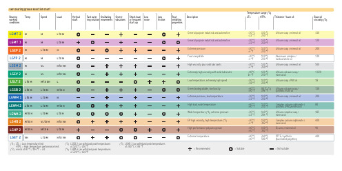
LGEV 2LGLT 2LGGB 2LGWM 1LGWM 2LGWA 2LGHB 2LGMT 2Bearing Temp Speed Load workingconditionsSKF bearing grease selection chartM M L to M (*1) L TL = Low-temperature limit HTPL = High-temperature performance limit (*2) mm 2/s at 40 °C / 104 °F = cSt.(*3) LGGB 2 can withstand peak temperatures of 120 °C / 250 °F(*4) LGWA 2 can withstand peak temperaturesof 220 °C / 428 °F(*5) LGHB 2 can withstand peak temperatures of 200 °C / 392 °FGeneral purpose industrial and automotive–30 °C120 °C Lithium soap / mineral oil 110 –22 °F 250 °F Description LTLHTPL Thickener / base oil Base oilviscosity (*2)Vertical Fast outer Oscillating SevereShock load Low Low Rust shaft ring rotation movements vibrations or frequent noise friction inhibitingstart-uppropertiesTemperature range (*1) = Recommended = Suitable = Not suitableM VL H to VH L to M M to EH L L to M L to M M to H L to M L to M H L to M L to M M to H M to H L to M L to H M to H VL to M H to VH Extremely high viscosity with solid lubricants –10 °C 120 °C Lithium-calcium soap / 1 020 14 °F 250 °F mineral oilLow temperature, extremely high speed –50 °C 110 °C Lithium soap / PAO oil 18 –58 °F 230 °F Green biodegradable, low toxicity –40 °C 90 °C (*3) Lithium-calcium soap / 110 –40 °F 194 °F synthetic ester oil Extreme pressure, low temperature –30 °C 110 °C Lithium soap / mineral oil 200 –22 °F 230 °F High load, wide temperature –40 °C 110 °C Complex calcium sulphonate / 80–40 °F 230 °F synthetic (PAO)/mineral oil Wide temperature (*4), extreme pressure –30 °C 140 °C Lithium complex soap / 185 –22 °F 284 °F mineral oilEP high viscosity, high temperature (*5) –20 °C 150 °C Complex calcium sulphonate / 400 –4 °F 302 °F mineral oilLGMT 2Basic bearing grease selectionSKF bearing greasesHighest quality grease for bearing lubrication Guarantee of consistent quality as each product is manufactured at one location to the same formulation A complete product programme for general and specific bearing lubrication requirements International standardisation of theSKF grease testing methods and equipment Worldwide product availability through the SKF dealer networkNote: – For areas with relatively high ambient temperatures, use LGMT 3 instead of LGMT 2– For special operating conditions, refer to the SKF bearing grease selection chartGenerally use if: Speed = M, Temperature = M and Load = M General purposeUnless:High temperatureExtremely high temperatureLow temperature High load Food processing “Green” biodegradableSKF SYSTEM 2435 g tube 200 g tube 420 ml cartridge 1 kg can 5 kg can 18 kg can 50 kg drum 180 kg drum 50 g (25 ml)syringe25 kg can Available pack sizes• • • • • • • • • • • • • • • • • • • • • • • • • • • • • • • • • • • • • • • • • • • • • • • • • • • • • • • • • • • • • • • • ••••• • • • • • • •••。
有关电子海图航线设计的一些认识
有关电子海图航线设计的一些认识作者:和新占来源:《珠江水运》2019年第07期摘要:本文讲述了电子海图(TOKYO KEIKI)的海图选取,航线设计及领海基线、低硫油区域、报告线的绘制。
关键词:海图航线设计由于电子海图的普及和使用,二副的航线设计也由传统的手写笔画变成了现在的鼠标键盘操作,中远海运船舶电子海图机器型号多为为TOKYO KEIKI EC-8000K/EC-8500K,下面是本人对电子海图航线设计的一些个人经验和大家分享。
1.航次海图的选取收到航次任务后,打开GATEWAY软件,在Catelogue界面内,左侧[Product Selection]界面选择 [AVCS Charts],通过点击[Route]-[New]大致画出计划航线,然后通过点击鼠标右键,弹出覆盖该点的所有海图,移动鼠标依次选取从始发港到目的港的最大比例尺海图。
后续操作在GATEWAY软件使用说明书均有说明,在次不再赘述。
下面是申请电子海图时的一些注意事项:(1)海图主管一般将电子海图Permit有效期设定为3个月,根据航次的长短的具体情况,申请海图,如果是长航线,如美洲航线,可分两段而分段申请,第一段从航次第一装货港至第一卸货港。
第二段从第二卸货港至航次结束港,在预抵第一卸货港10天前左右申请。
如果是短航线,可一次性申请航次全部海图。
一般情况下,应尽量减少申请海图的次数,其一是为了减少海图出错的概率,其二也可以减少工作负担。
(2)电子海图Permit的有效期是按整月计算的,而不是以申请的日期顺延3个月。
例如2018年9月28日申请电子海图Permit,则其有效期至2018年11月30日,而不是2018年12月28日。
所以应尽量避免在月底申请电子海图,长航线应特别注意。
(3)有些海区电子海图没有覆盖,特别是一些港口﹑海峡﹑运河,如智利港口HUASCO,查英版Catelogue NP131,港口区域有大比例尺纸质港图覆盖,而电子海图没有覆盖。
ABAQUS常见问题汇总
ABAQUS 常见问题汇总 - 2.0 版
目录 点击小节标题,可以跳到相应的内容(有些 WORD 版本可能需要按住 ctrl 键)
0. ABAQUS 入门资料.......................................................................................................................... 4
6.1 ABAQUS 安装方法 ................................................................................................................. 12 6.2 ABAQUS 显示异常(无法显示栅格、显卡冲突、更改界面颜色).......................................... 21 6.3 Document 无法搜索................................................................................................................. 21 6.4 磁盘空间不足 ........................................................................................................................... 22 6.5 Linux 系统................................................................................................................................ 22 6.6 死机后恢复模型 ....................................................................................................................... 23
论数控系统中常用的英语单词
数控系统中常用的英语单词目前数控系统大多使用英语,为方便使用数控设备时查找,在下面列出了数控系统中比较常用的英文词汇。
其中的汉语解释只侧重于它们在数控系统中的含义,而对其它含义则予以忽略。
单词词义board n.板卡fine adj.精密的word n.字ABS(absolute) adj.绝对的absolute adj.绝对的AC n.交流accelerate v.加速acceleration n.加速度active adj.有效的adapter n.适配器,插头address n.地址adjust v.调整adjustment n.调整advance v.前进advanced adj.高级的,增强的alarm n.报警ALM(alarm) n.报警alter v.修改amplifier n.放大器angle n.角度APC n.绝对式脉冲编码器appendix n.附录,附属品arc n.圆弧argument n.字段,自变量arithmetic n.算术arrow n.箭头AUTO n.自动automatic adj.自动的automation n.自动auxiliary function 辅助功能axes n.轴(复数)axis n.轴background n.背景,后台backlash n.间隙backspace v.退格backup v.备份bar n.栏,条battery n.电池baudrate n.波特率bearing n.轴承binary adj..二进制的bit n.位blank n.空格block n.撞块,程序段blown v.熔断bore v.镗boring n.镗box n.箱体,框bracket n.括号buffer n.v.缓冲bus n.总线button n.按钮cabient n.箱体calbe n.电缆calculate v.计算calculation n.计算call v.调用CAN(cancel) v.清除cancel v.清除canned cycle 固定循环capacity n.容量card n.板卡carriage n.床鞍,工作台cassette n.磁带cell n.电池CH(chanel) n.通道change v.变更,更换channel n.通道check v.检查chop v.錾削chopping n.錾削circle n.圆circuit n.电路,回路circular adj.圆弧的clamp v.夹紧clear v.清除clip v.剪切clip board n.剪贴板clock n.时钟clutch n.卡盘,离合器CMR n.命令增益CNC 计算机数字控制code n.代码coder n.编码器command n,v.命令communication n.通讯compensation n.补偿computer n.计算机condition n.条件configuration n.配置configure v.配置connect v.连接connection n.连接connector n.连接器console n.操作台constant n.常数,adj.恒定的contour n.轮廓control v.控制conversion n.转换cool v.冷却coolant n.冷却coordinate n.坐标copy v.拷贝corner n.转角correct v.改正,adj.正确的correction n.修改count v.计数counter n.计数器CPU n.中央处理单元CR n.回车cradle n.摇架create v.生成CRT n.真空射线管CSB n.中央服务板current n.电流,当前的,缺省的current loop n.电流环cursor n.光标custom n.用户cut v.切削cutter n.(元盘形)刀具cycle n.循环cylinder n.圆柱体cylindrical adj.圆柱的data n.数据(复数)date n.日期datum n.数据(单数)DC n.直流deceleration n.减速decimal point n.小数点decrease v.减少deep adj.深的define v.定义deg. n.度degree n.度DEL(delete) v.删除delay v,n.延时delete v.删除deletion n.删除description n.描述detect v.检查detection n.检查device n.装置DGN(diagnose) v.诊断DI n.数字输入DIAG(diagnosis) n.诊断diagnosis n.诊断diameter n.直径diamond n.金刚石digit n.数字dimension n.尺寸,(坐标系的)维DIR n.目录direction n.方向directory n.目录disconnect v.断开disconnection n.断开disk n.磁盘diskette n.磁盘display v,n.显示distance n.距离divide n,v除,v.划分DMR n.检测增益DNC 直接数据控制DO n.数字输出dog switch n.回参考点减速开关DOS n.磁盘操作系统DRAM n.动态随机存储器drawing n.画图dress v.修整dresser n.修整器drill v.钻孔drive v.驱动driver n.驱动器dry run 空运行duplicate v.复制duplication n.复制dwell n,v.延时edit v.编辑EDT(edit) v.编辑EIA n.美国电子工业协会标准electrical adj.电气的electronic adj.电子的emergency n.紧急情况enable v.使能encoder n.编码器end v,n.结束enter n.回车,v.输入,进入entry n.输入equal v.等于equipment n.设备erase v.擦除error n.误差,错误,故障Esc=escape v.退出exact adj.精确的example n.例子exchange v.更换execute v.执行execution n.执行exit v.退出external adj.外部的failure n.故障FANUC n.(日本)法那克fault n.故障feed v.进给feedback v.反馈feedrate n.进给率figure n.数字file n.文件filt(filtrate) v.过滤filter n.过滤器Fin(finish) n.完成(应答信号)fine adj.精密的fixture n.夹具FL (回参考点的)低速flash memory n.闪存flexible adj.柔性的floppy adj.软的foreground n.前景,前台format n.格式,v.格式化function n.功能gain n.增益GE FANUC GE法那克gear n.齿轮general adj.总的,通用的generator n.发生器geometry n.几何gradient n.倾斜度,梯度graph n.图形graphic adj.图形的grind v.磨削group n.组guidance n.指南,指导guide v.指导halt n,v.暂停,间断handle n.手动,手摇轮handy adj.便携的handy file 便携式编程器hardware n.硬件helical adj.螺旋上升的help n,v.帮助history n.历史HNDL(handle) n.手摇,手动hold v.保持hole n.孔horizontal a.水平的host n.主机hour n.小时hydraulic adj.液压的I/O n.输入/输出illegal adj.非法的inactive adj.无效的inch n.英寸increment n.增量incremental adj.增量的index 分度,索引initial adj.原始的initialization n.C523初始化initialize v.初始化input n.v.输入INS(insert) v.插入insert v.插入instruction n.说明interface n.接口internal adj.内部的interpolate v.插补interpolation n.插补interrupt v.中断interruption n.中断intervent n.间隔,间歇involute n.渐开线ISO n.国际标准化组织jog n.点动jump v.跳转key n.键keyboard n.键盘label n.标记,标号ladder diagram 梯形图language n.语言lathe n.车床LCD n.液晶显示least adj.最小的length n.长度LIB(library) n.库library n.库life n.寿命light n.灯limit n.极限limit switch n.限位开关line n.直线linear adj.线性的linear scale n.直线式传感器link n,v.连接list n,v.列表load n.负荷,v.装载local adj.本地的locate v.定位,插销location n.定位,插销lock v.锁定logic n.逻辑look ahead v.预,超前loop n.回路,环路LS n.限位开关LSI n.大规模集成电路machine n.机床,v.加工macro n.宏macro program n.宏程序magazine n.刀库magnet n.磁体,磁magnetic a.磁的main program n.主程序maintain v.维护maintenance n.维护MAN(manual) n.手动management n.管理manual n.手动master adj.主要的max adj.最大的,n.最大值maximum adj.最大的,n.最大值MDI n.手动数据输入meaning n.意义measurement n.测量memory n.存储器menu n.菜单message n.信息meter n.米metric adj.米制的mill n.铣床,v.铣削min adj.最小的,n.最小值minimum adj.最小的,n.最小值minus v.减,adj.负的minute n.分钟mirror image n.镜像miscellaneous function n.辅助功能MMC n.人机通讯单元modal adj.模态的modal G code n.模态G代码mode n.方式model n.型号modify v.修改module n.模块MON(monitor) v.监控monitor v.监控month n.月份motion n.运动motor n.电机mouse n.鼠标MOV(移动)v.移动move v.移动movement n.移动multiply v.乘N number n.程序段号N.M n.牛顿.米name n.名字NC n.数字控制NCK n.数字控制核心negative adj.负的nest v,n.嵌入,嵌套nop n.空操作NULL n.空number n.号码numeric adj.数字的O number n.程序号octal adj.八进制的OEM n.原始设备制造商OFF adv.断offset n.补偿,偏移量ON adv.通one shot G code 一次性G代码open v.打开operate v.操作operation n.操作OPRT(operation) n.操作origin n.起源,由来original adj.原始的output n,v.输出over travel 超程over voltage 过电压overcurrent 过电流overflow v,n.溢出overheat n.过热overload n.过负荷override n.(速度等的)倍率page n.页page down 下翻页page up 上翻页panel n.面板PARA(parameter) n.参数parabola n.抛物线parallel adj.平行的,并行的,并联的parameter n.参数parity n.奇偶性part n.工件,部分password n.口令,密码paste v.粘贴path n.路径pattern n.句型,式样pause n.暂停PC n.个人电脑PCB n.印刷电路板per prep.每个percent n.百分数pitch n.节距,螺距plane n.平面PLC n.可编程序逻辑控制器plus n.增益,prep.加,adj.正的PMC n.可编程序逻辑控制器pneumatic adj.空气的polar adj.两极的,n.极线portable adj.便携的POS(position) v,n.位置,定位position v,n.位置,定位position loop n.位置环positive adj.正的power n.电源,能量,功率power source n.电源preload v.预负荷preset v.予置pressure n.压力preview v.予览PRGRM(program) v.编程,n.程序print v.打印printer n.打印机prior adj.优先的,基本的procedure n.步骤profile n.轮廓,剖面program v.编程,n.程序programmable adj.可编程的programmer n.编程器protect v.保护protocol n.协议PSW(password) n.密码,口令pulse n.脉冲pump n.泵punch v.穿孔puncher n.穿孔机push button n.按钮PWM n.脉宽调制query n.问题,疑问quit v.退出radius n.半径RAM n.随机存储器ramp n.斜坡ramp up v.(计算机系统)自举range n.范围rapid adj.快速的rate n.比率,速度ratio n.比值read v.读ready adj.有准备的ream v.铰加工reamer n.铰刀record v,n.记录REF(reference) n.参考reference n.参考reference point n.参考点register n.寄存器registration n.注册,登记relative adj.相对的relay v,n.中继remedy n.解决方法remote adj.远程的replace v.更换,代替reset v.复位restart v.重启动RET(return) v.返回return v.返回revolution n.转rewind v.卷绕rigid adj.刚性的RISC n.精简指令集计算机roll v.滚动roller n.滚轮ROM n.只读存储器rotate v.旋转rotation n.旋转rotor n.转子rough adj.粗糙的RPM n.转/分RSTR(restart) v.重启动run v.运行sample n.样本,示例save v.存储save as 另存为scale n.尺度,标度scaling n.缩放比例schedule n.时间表,清单screen n.屏幕screw n.丝杠,螺杆search v.搜索second n.秒segment n.字段select v.选择selection n.选择self-diagnostic 自诊断sensor n.传感器sequence n.顺序sequence number 顺序号series n.系列,adj.串行的series spindle n.数字主轴servo n.伺服set v.设置setting n.设置shaft n.轴shape n.形状shift v.移位SIEMENSE (德国)西门子公司sign n.符号,标记signal n.信号skip v,n.跳步slave adj.从属的SLC n.小型逻辑控制器slide n.滑台,v.滑动slot n.槽slow adj.慢soft key n.软键盘software n.软件space n.空格,空间SPC n.增量式脉冲编码器speed n.速度spindle n.主轴SRAM n.静态随机存储器SRH(search) v.搜索start v.启动statement n.语句stator n.定子status n.状态step n.步stop v.停止,n.挡铁store v.储存strobe n.选通stroke n.行程Subprogram n.子程序sum n.总和surface n.表面SV(servo) n.伺服switch n.开关switch off v.关断switch on v.接通symbol n.符号,标记synchronous adj.同步的SYS(system) n.系统system n.系统tab n.制表键table n.表格tail n.尾座tandem adv.一前一后,串联tandem control n.纵排控制(加载预负荷的控制方式)tank n.箱体tap n,v.攻丝tape n.磁带,纸带tape reader n.纸带阅读机tapping n.攻丝teach in 示教technique n.技术,工艺temperature n.温度test v,n.测试thread n.螺纹time n.时间,次数tolerance n.公差tool n.刀具,工具tool pot n.刀杯torque n.扭矩tower n.刀架,转塔trace n.轨迹,踪迹track n.轨迹,踪迹tranducer n.传感器transfer v.传输,传送transformer n.变压器traverse v.移动trigger v.触发turn v转动,n转,回合turn off v.关断turn on v.接通turning n.转动,车削unclamp v.松开unit n.单位,装置unload n.卸载unlock v.解锁UPS n.不间断电源user n.用户value n.值variable n.变量,adj.可变的velocity n.速度velocity loop n.速度环verify v.效验version n.版本vertical a.垂直的voltage n.电压warning n.警告waveform n.波形wear n,v.磨损weight n.重量,权重wheel n.轮子,砂轮window n.窗口,视窗workpiece n.工件write v.写入wrong n.错误,adj.错的year n.年zero n.零,零位zone n.区域。
(完整word版)全新版大学进阶英语第三册第三单元答案解析
Key to ExercisesOpenerSuggested answers for reference:1。
In China it is a familiar scene that grandparents take their grandchildren to or from school every day, which, however,seldom happens in the West. There parenting responsibility mainly rests with the parents rather than others。
2。
In general there is not much difference between Western and Chinese tourists。
If any, it seems that Chinese like to pose for photos with the scenery as the background,whereas Westerners often just shoot pictures of scenic spots。
3. Well,it’s true that many Western employees see them and their boss as equals, but anywhere,anytime,you and your boss are never equals in its truest sense. There always exists a gap in between. Compared with Westerners, Chinese employees might tend to be more forbearing (克制) towards their boss and seldom air their grievances publicly.Reading & InteractingI。
LCR22 LCR30系列产品说明书
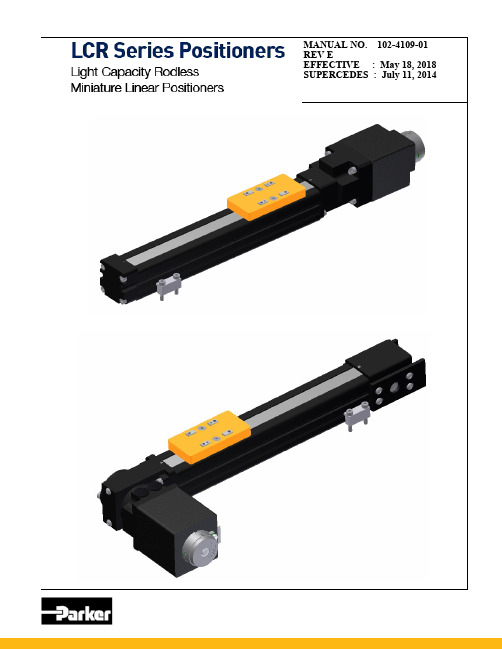
MANUAL NO. 102-4109-01 REV EEFFECTIVE : May 18, 2018 SUPERCEDES : July 11, 2014For assistance contact:Parker Hannifin Corporation Electro Mechanical Division 1140 Sandy Hill Road Irwin , PA 15642Ph 724-861-8200 800-245-6903E -mail:***************** LCR22/LC30 Series Product ManualChapter 1 Introduction (5)Product Description (5)Unpacking (5)Warranty Repair (6)Warnings Precautions (6)Specification Conditions (7)Chapter 2 LCR Specifications (9)Configurable Part Number (9)LCR22 Screw Drive Dimensional Drawing (10)LCR30 Belt Drive Dimensional Drawing (11)LCR22 Screw Drive Dimensional Drawing (12)LCR30 Belt Drive Dimensional Drawing (13)LCR22 Idler Dimensional Drawing (14)LCR30 Idler Dimensional Drawing (14)LCR22 Screw Drive Performance Specifications (15)LCR30 Screw Drive Performance Specifications (15)LCR22 Belt Drive Performance Specifications (17)LCR30 Belt Drive Performance Specifications (17)Chapter 3 Component Specifications (19)Motor Specifications (20)Stepper Motor Encoder Specifications (21)Limit Home Switch Specifications (22)LCR22 Screw Drive Reflected Inertias (23)LCR22 Maximum Allowable Speeds (23)LCR30 Screw Drive Reflected Inertias (23)LCR30 Screw Drive Maximum Allowable Speeds (23)Chapter 4 Set up and Usage (25)Base Mounting (25)Coupling Installation Screw Drives (25)Payload Mounting (26)Moment Load Pre-Cautions (26)Limit/Home Adjustment (27)Chapter 5 Maintenance and Repair (28)Lubrication (28)LCR22 Belt Drive Motor Mounting (28)LCR30 Belt Drive Motor Mounting (29)LCR Belt Drive Tensioning (30)Strip Seal Replacement (33)Accessories & Spare Parts List (34)Chapter 6 Compliance Documents (36)REVISON NOTES_____________________________________________________________________ REV 1 INITIAL RELEASE 5-15-11REV 2 Rebranded drive as P23/2013REV 3 Fixed some missed Ion references, added CE warnings 1/29/14REV 4 Wrap update, LCR changes 7/14/14REV E C slot sensor update - p. 22,27,34Chapter 1 - IntroductionProduct DescriptionLCR PositionerUnpackingUnpackingCarefully remove the positioner from the shipping container and inspect the unit for any evidence of shipping damage. Report any damage immediately to your local authorized distributor. Please save the shipping con-tainer for damage inspection or future transportation.Incorrect handling of the positioner may adversely affect the performance of the unit in its application. Stand-ard handling and lifting practices should be employed, product may be heavy.Please observe the following guidelines for handling and mounting of your new positioner.DO NOT allow the positioner to drop onto the mounting surface. Dropping the positioner can generate im-pact loads that may result in flat spots on bearing surfaces or misalignment of drive components.DO NOT drill holes into the positioner. Drilling holes into the positioner can generate particles and machin-ing forces that may effect the operation of the positioner. Parker will drill holes if necessary; contact your local authorized distributor.DO NOT subject the unit to impact loads such as hammering, riveting, etc. Impacts loads generated byhammering or riveting may result in flat spots on bearing surfaces or misalignment of drive compo-nents.DO NOT lift the positioner by cables or cable management system. Lifting positioner by cables or cablemanagement system may effect electrical connections and/or cable management assembly. The unit should be lifted by the base structure only.DO NOT expose positioner to mist, spray or submersion in liquids.DO NOT disassemble positioner. Unauthorized adjustments may alter the positioner ’s specifications andvoid the product warranty.Thank you for your interest in the Light Capacity Rodless (LCR) series miniature actuators. The LCR is designed for maximum flexibility to deliver the most value for the customer. The LCR is ideal for Maldiplate, Titer tray, and slide automation , as well as any light weight payload. The “off the shelf ” product will significantly reduce design , procurement, inspection, and handling time; in turn bringing your product to market faster. The following user guide will direct you in any needed maintenance items and basic features of the LCR series. If you have any questions or challenges please call our factory support team at 800-245-6903.Return InformationReturnsAll returns must reference a “R eturn M aterial A uthorization” (RMA) number. Please call your local author-ized distributor or Parker Customer Service Department at 800-245-6903 to obtain a “RMA” number. Repair InformationOut-of-Warranty RepairOur Customer Service Department repairs Out-of-Warranty products. All returns must reference a “RMA”number. Please call your local authorized distributor or Parker Customer Service Department at 800-245-6903 to obtain a “RMA” number. You will be notified of any cost prior to making the repair. Warnings and PrecautionsHot SurfacesDO NOT touch rotary motor coils located on the MX45S after high duty operation. Motortemperature may approach 60°C. The unit itself may become warm or hot to the touch.Electrical ShockDO NOT take apart or touch any internal components of the positioner while unit is pluggedinto an electrical outlet. SHUT OFF power before replacing components to avoid electricalshock.Pinch PointsUnit may have a pinch point because the top extends over the base of the table. Proper careshould be exercised.Vertical OperationDepending upon your load and screw selection the carriage and load may ‘backdrive’ in pow-er loss situations potentially causing product damage or personal injury.General SafetySometimes positioners move without warning, keep all personnel away from dynamic travelrange of positioner.Strain Relieve Electrical ComponentsAll electrical components (such as motor, encoders and limit/home switches) must be strainrelieved. Failure to strain relieve electrical wires or cables may result in component failureand/or possible personal injury.High Magnetic FieldUnit may be HAZARDOUS to people with Pace Makers or any other ‘magnetically-sensitive’medical devices. Unit may have an effect on ‘magnetically-sensitive’ applications.Moving CablesIf the LCR cables are to be moving, the use of high flex cabling to insure long life isrecommended.Specification ConditionsSpecifications Are Temperature DependentCatalog specifications are obtained and measured at 20 Degrees C. Specifications at any othertemperature may deviate from catalog specifications. Minimum to maximum continuous operatingtemperature range (with NO guarantee of any specification except motion) of a standard unit beforefailure is 5 - 40 degrees C.Specifications Are Mounting Surface DependentCatalog specifications are obtained and measured when the positioner is fully supported, bolteddown, and is mounted to a work surface that has a maximum flatness error of:0.001mm/300mm (0.00004”/ft)Table will operate with work surface of 0.100mm/300mm flatness or worse, but performance speci-fications will be significantly effected.Specifications Are Point of Measurement DependentCatalog specifications and specifications in this manual are measured from the center of the car-riage, 38 mm above the carriage surface. All measurements taken at any other location may devi-ate from these values.Specifications Are Load Mounting DependentCatalog specifications are obtained and measured when the customer load is fixed to the carriagemounting surface(s) and has a flatness of equal to or less than 0.0025mm (0.0001”). The table willoperate with customer load surface greater than 0.0025mm (0.0001”) flatness, but performancespecifications will be significantly effected.P2 DRIVEChapter 2 - LCR Specifications LCR–How to OrderLCR22/LCR30 SERIES PRODUCT MANUAL__________________Dimensional Drawings– LCR22 Leadscrew DriveDimensional Drawings–LCR30 Leadscrew DriveDimensional Drawing– LCR22 Belt DriveDimensional Drawings–LCR30 Belt DrivePerformance Specifications–LCR Screw Driven• Moment loading : Moment ratings are reduced ,when multiple moments/forces are applied , see page 26.LCR Screw -Driven SpecificationsLinear Speed Versus Thrust GraphsPerformance Graph Notes:To simplify application, the different aspects of positioner performance including motor torque, motor speed, screw efficiency, friction, safety margin, etc. have been consolidated into these speed versus thrust graphs. To make a selection first use the X axis scale of the different graphs to identify a screw lead that will deliver the desired peak velocity. Next, using the specific screw lead graph, identify the motor with enough torque to deliver the needed thrust to lift or accelerate the load.*Maximum speed with Parker P2 stepper drive at 24 VDC. To achieve faster speeds, motor must be connected to a drive with active damping, electronic viscosity or other advanced anti -resonance zone features.Performance Specifications–LCR Belt Driven* Moment loading : Moment ratings are reduced ,when multiple moments/forces are applied , see page 26.Performance Graph Notes:To simplify application, the different aspects of positioner performance including motor torque, motor speed, efficiency, friction, safety margin, etc. have been consolidated into these speed versus thrust graphs. To make a selection first use the X axis scale of the different graphs to identify a screw lead that will deliver the desired peak velocity. Next, using the specific screw lead graph, identify the motor with enough torque to deliver the needed thrust to lift or accelerate the load.Chapter 3– Component SpecificationsServo Motor Connector Pin OutsStepper Motor Wire Color CodeMotor Information006-2357-(1.0/3.0) Stepper Motor Power Extension CableConnector PinFunction Pin 1 A+ Pin 2 A - Pin 3 B+ Pin 4B -Motor Cable Connector Pin OutLCR Stepper Motor EncoderLimit/Home Switch Information* P/N 003-2918-01 5m flying lead extension cable is availableLCR22/LCR30 SERIES PRODUCT MANUAL__________________ LCR Motor Sizing Information : Screw DrivesLCR Motor Sizing information : Belt Drive InformationChapter 4– Setup and UsageInstallation of coupling half onto Motor Shaft: (LCR 22/30 Screw Drive option only. See Chapter 5 for Belt Drive motor mounting .)Screw driven actuators : To provide coupling engagement and avoid preloading motor bearing, the coupling half Must be accurately placed on motor shaft. See chart below.Set screw of coupling should be aligned to flat on motor and torque to 0.5 N -mBase MountingSecuring the LCR22/LCR30 is done by toe clamp mountingProper mounting of the LCR is essential to optimum product performance and to ensure safety.Toe clamp centers “C ”:“C ”= 28.5MM LCR22 “C ”= 36.5MM LCR30Tap depth recommended to be M3 x 0.5 x 7.0LG. minimumPayload Mounting–LCR22/30Payload mounting to LCR using the M3 x0.5 (LCR30) M2.0 x 0.4 (LCR22) in the load plate. When fastening to load take precaution in using screws with no more than 5.5mm of thread engagement, as to not damage positioner.The LCR30 contains 2.5 diameter H7 (slip fit) dowel holes for repeatable mounting to customer load plate if desired.See pages 10 thru 13 for detailed carriage specifications.WARNING : To avoid damage to nut-carriage assemblyDo not back drive (push by hand) the carriage. Carriage should be only moved by input to thedrive shaft via motor or hand crank.Moment loading pre-cautions :The LCR positioners have rated individual moment and load ratings. When multiplemoments are applied to carriage these rating must be reduced use the equation below as a guideline.Moment Factor:Take each existing moment/ corresponding maximum allowable moment = moment factor.Sum all the moment factors and result must be less than 1.8Example : LCR30 screw drive sq rail version with the following:Mroll =0.5 N-m = 0/2.6 (0.00)Mpitch =2.5 N-m = 2.5/8.2 (0.30)Myaw =1.0 N-m =1.0/6.5 (0.15)SUM THE ABOVE=(0.00+0.30+0.15)=0.45 WHICH IS LESS THAN 1.8Moment loading is acceptable.Limit/Home Switch Mounting/AdjustmentTravel limit sensors signal the motor to stop whenever the carriage is approaching end of travel. The home sensor provides a fixed reference point to which the carriage can be commanded to return repeatedly.If equipped the LCR limit home switches are installed at factory but not set. To adjust the switches . Loosen the flat head screw by turning (CCW) and position the switch to desired location and then retighten.Insert the switch into c-slot ( screw head facing up and then rotate 90’) and mountThe limit switches must be inserted into the top c-slot for the magnet in carriage to trigger.The limit switches can be mounted to either side of unitSee page 22 for detailed switch specificationsChapter 5–Maintenance and Repair LubricationNo lubrication is required in standard operating conditions.LCR BELT DRIVE INFORMATION:Mounting Motor to LCR22 belt drivesMount motor to motor block by inserting the motor /motor shaft into input shaft of table. Secure motor with its mounting hardware to motor block.Tighten the clamp collar(003-2604-08) to secure to 1.9 N-m (16 in-lbs).Mounting Motor to LCR30 belt drives1.Mount Oldham coupling half onto motor shaft according to table below.Torque coupling bolt to 11.0 in-lbs (1.24 Nm).Note: To provide proper coupling engagement and avoid preloading the motor bearing, the coupling half must be accurately placed on the motor shaft.2.Insert Plastic Torque Disc onto coupling.3.Note: Orientation of Torque Disc “key way” and corresponding “key” on hub shaft inside LCR 30 housing.Rotate motor shaft to align both parts.4.Insert motor with coupling and torque disc into LCR30 housing, making sure coupling “key” and “key way” are aligned.5. Tighten motor mounting bolts to secure motor to mounting blockLCR BELT DRIVE INFORMATION:Replacing Belt :One should remove the idler cover plate and drive end cover plate.Remove strip seal per instruction page 32.*Extra care should be taken when coming into contact with strip seals as they are very sharp.Remove the carriage load plateRemove belt from UnitDo not discard belt. One should use this belt as a guide to cutting the replacement belt to proper length.Cut new/replacement belt to match old belt. Put to sideNext go to idler end and loosen the 8 (4 each side) button head screws attaching the belt tension plates to allow the tension plate to slide , one will also have to back out the set screws in the end of plates to allow the tension plate to be pushed to a position that puts the plate and idler pulley closest to base extrusion. And then lightly tighten the 8button heads so tension plates and pulley are fixed.Replace beltRun belt under drive pulley and into pocket of base. The use of screw driver /allen key can assiat into assuring the belt enters the pocket in base and does not raise up into main body extrusion. Push belt through extrusion and use same screw driver/allen key to assist in allowing belt to go under idler pulley and out the idler end.Wrap the belt around the drive and idler pulleys and bring belt ends to carriage. Make sure the tension plates are fixed as stated on previous page( pushed toward the base extrusion.) . Lay Belt teeth on carriage teeth as shown. Make sure to achieve at least 5 teeth engament of belt on each side and then place/mount top of carriage to clamp belt utilizing the Qty2 socket head fasteners..LCR22 Bushing carriage employs clamping nuts and requires the belt be punched with 2.0mm hole.Once the belt is clamped via the carriage top . Next is to tension the belt. Replace the cover plate on idler endBELT TENSION CONTINUEDNow tighten the qty button heads that secure the tension plates into position. Remove the belt tension fixture Re -insert the flat head set screws.Remove the flat head set screws in the tension plates Utilize belt tension fixture to provide uniform tension/pull force on tension plates/belt. P/N 005-3044-01 LCR 22 provides pull force of 80N and a belt tension of 40N P/N 005-3044-02 LCR 30 provides pull force of 120N and a belt tension of 60NStrip Seal ReplacementREPLACEMENT OF STRIP SEAL AS FOLLOWS:1. Remove the yellow load plate , QTY 2 M3 X 0.5 X 6.0 LG Socket flat heads w 2mm allen key.2. Loosen the QTY 2 M2 X 0.4 X 6LG socket head set screws with 1.27mm alleny key3. Remove and replace strip seal.4.Reverse the steps above*Extra care should be taken when coming into contact with strip seals as they are very sharp.Accessories & Spare PartsLCR22/LCR30 SERIES PRODUCT MANUAL__________________ Accessories :XYZ BracketryLCR22/LCR30 SERIES PRODUCT MANUAL__________________Compliance DocumentsWe hereby certify that the LCR product line, produced by Parker Hannifin Corporation, complies with the requirements of the EU Directive 2011/65/EU on the restriction ofLCR22/LCR30 SERIES PRODUCT MANUAL__________________。
313轴承尺寸参数
313轴承尺寸参数引言313轴承是一种常见的机械零件,广泛应用于各种旋转设备中。
为了确保轴承能够正常运转,我们需要了解313轴承的尺寸参数。
本文将对313轴承的尺寸参数进行全面、详细、完整且深入地探讨。
313轴承的基本结构313轴承由内外圈、滚动体和保持架组成。
其中,内圈和外圈的直径决定了轴承的尺寸大小,滚动体的直径决定了轴承的承载能力,保持架则起到固定滚动体的作用。
313轴承的主要尺寸参数313轴承的尺寸参数包括内圈直径、外圈直径、滚动体直径和保持架尺寸等。
内圈直径内圈直径是指313轴承内圈的直径。
内圈直径的大小直接影响着轴承的安装和使用。
内圈直径通常以毫米(mm)为单位进行表示。
外圈直径外圈直径是指313轴承外圈的直径。
外圈直径的大小决定了轴承在外部设备中的安装空间。
外圈直径通常以毫米(mm)为单位进行表示。
滚动体直径滚动体直径是指313轴承滚动体的直径。
滚动体直径的大小与轴承的承载能力有直接关系。
滚动体直径通常以毫米(mm)为单位进行表示。
保持架尺寸保持架尺寸包括保持架的宽度和长度。
保持架的尺寸大小会影响轴承的稳定性和使用寿命。
保持架尺寸通常以毫米(mm)为单位进行表示。
313轴承尺寸参数的选择在选择313轴承尺寸参数时,需要考虑以下几个因素:轴承负荷轴承的尺寸参数应能够承受所施加的负荷。
负荷包括径向负荷和轴向负荷,轴承的尺寸参数应能够满足负荷的需求。
轴承速度轴承的尺寸参数还应能够适应所需的转速。
根据轴承的尺寸和材料,轴承的行程可以适应不同的转速。
轴承的可用空间轴承的尺寸参数应能够适应安装空间的限制。
在选择轴承时,要确保轴承的尺寸与设备的空间要求相匹配。
轴承的使用寿命轴承的尺寸参数还要符合设备的使用寿命要求。
过小的尺寸可能导致轴承寿命过短,过大的尺寸可能导致设备结构的不稳定。
313轴承尺寸参数的标识方法313轴承的尺寸参数通常以数字或字母的形式进行标识。
常见的标识方法包括:1.内圈直径以字母“d”表示,外圈直径以字母“D”表示,滚动体直径以字母“B”表示,保持架尺寸以字母“C”表示。
轴承方面专业单词英日对照

Deep groove ball brgs 深溝玉軸受けAngular contact ball brgs アンギュラ玉Self-aligning ball brgs自動調心Cylindrical roller brgs 円筒ころTaper e d roller brgs円錐ころSpherical roller brgs 自動調心ころThrust brgsスラストNeedle roller brgs針状ころSingle-row deep groove ball bearing 単列深溝玉軸受Snap ring とめ輪Cage 保持器Rivet リベット铆钉Inner ring raceway内輪軌道Outer ring raceway外輪軌道Chamfer dimension 面取寸法Side face 側面Shield シールド防尘盖Outside dia 軸受け外径Pitch diameterピッチ円径Bore dia軸受内径Single-row angular contact ball bearing 単列アンギュラ玉軸受Contact angle 接触角Outer ring front face外輪正面Inner ring back face内輪背面Effective load center作用点Outer ring back face 外輪背面Inner ring front face内輪正面Cross face width組み立て幅(内輪のは背面から外輪の背面までの寸法)Cylindrical roll bearing 円筒ころ軸受Outer ring rib外輪つば外圈挡边L –shaped thrust collar L形つば輪斜挡边Roller inscribed circle dia ころ内接円径滚子内接圆径Cylindrical roller 円筒ころTapered roller bearing 円錐ころ軸受Stand out 差幅Tapered roller 円錐Cone back face rib 大つばCone back face 内輪の背面Cup front face 外輪の正面Cup back face 外輪の背面Cone front face 内輪の正面Contact angle 接触角Cone front face rib小つばSpherical roller bearing 自動調心ころ軸受Tapered bore テ-パ穴圆锥孔Inner ring 内輪Spherical roller 球面ころOuter ring 外輪Lock washer 座金垫圈Nut ナット螺母Sleeve スリープ套筒Adapter アダプタ紧定套Type and features of rolling bearingBearing Selection procedure(程序步骤)Load capacity 荷重Permissible speed 許容回転数Misalignment of inner/outer rings 内輪と外輪の傾きRigidity 鋼性Noise and torque of various bearing 音響トルクと軸受形式Running accuracy and bearing types 回転精度Mounting and dismounting of various bearing types 取りつけ取り外しと軸受形式Fixed end and free end bearings固定側及び自由側軸受Bearing arrangementRolling fatigue life and basic rating life 転がり疲れ寿命基本定格寿命Destination 目的地Validity 确认允许Inspection 检查Prior 有限的在。
泵产品拆卸说明书

Refer to appropriate model instruction sheet before beginning procedures.Disassembly Instructions:Prepare a clean location free of debris. Carefully handle all components. Disassembled pump should be placed on a clean lint free cloth. If a keyed drive shaft is used the key should be removed at this time. Observe for and correct any sharp edges on keyway.Clamp front body in a soft jaw vice. For reference, scribe a line parallel with the shaft across the front body and rear cover. Remove hex head body bolts (see table 1) and pull rear cover over cartridge assembly.Table 1:Pump Socket Size Nominal TorquePFV*253/4 in. socket45 ft-lbsPFV*3515/16 in. socket70 ft-lbsPFV*451-1/8 in. socket250 ft-lbsGrasp cartridge assembly and pull it out of front body and over drive shaft. To change direction of rotation proceed to Direction of Rotation. Unseat spiral ring from front body by inserting a flat blade screw driver at slot in spiral ring. Guide the screw driver blade around ring to uncoil. Pull shaft out of front body. Remove washer from shaft seal and set aside. With snap ring pliers spread snap ring outward and remove from shaft. Remove bearing from shaft with an arbor bearing press. Inspect and replace any items as required.Direction of Rotation:Change of pump rotation is accomplished by converting the cartridge assembly. Note: Rotation is specified as viewed from pump shaft end. Vane tip leads direction of rotation (see figure 2).Remove the two socket head cap screws (see table 2) and interchange the location of inlet support plate and outlet support plate. Flex plate version must have the bronze surfaces toward rotor/vane assembly (see figure 1). Insert the two socket head cap screws finger tight.T o insure alignment of the assembly, place the cartridge into the front body and adjust as needed. If available, “V” blocks will be useful in reassembly. Tighten socket head cap screws to specified torque values.Table 2:Pump Wrench Size Nominal TorqueCK20PFVI9/64 in30 in-lbsCK20PFVH 3 mm30 in-lbsCK25PFV*5/32 in45 in-lbsCK35PFV*3/16 in105 in-lbsCK45PFV*3/16 in105 in-lbsSeal Replacement:Note the shape and orientation of all seals and seal back up rings beforeand during removal.With a blunt tip instrument (don’t use an awl or knife etc...) remove o-ringseal from front body, sealing ring, o-ring and back-up ring from outlet supportplate. A socket or dowel (see table 3) may be used to drive the shaft seal outof the front body.Table 3:PFV*25 1.475" (37mm) approximate outer diameterPFV*35 1.750" (44mm) approximate outer diameterPFV*45 2.0" (50mm) approximate outer diameterInspect and clean any foreign material from sealing areas. Install new back-up ring (back-up ring will be located outboard of o-ring) and o-ring ontooutlet support plate (see figure 1). Apply a film of clean oil on the replacementshaft seal inner and outer seal diameter and sealing ring. Gently tap withplastic hammer into front body with open end (spring visible) facing the rearcover. It may be helpful to use a socket or dowel to seat the shaft seal (seetable 3). Install sealing ring into front body. Run a finger around seals toinsure seating of all items. Flex plate versions have four (4) seals and back-up pack. Refer to Direction of Rotation for disassembly.Reassembly Instructions:Insert drive shaft into bearing with arbor bearing press. Press bearing until itstops against shoulder on shaft. Position snap ring in groove against bearinginner race. Place washer over shaft seal in front body.Lubricate drive shaft end with clean oil and carefully insert shaft throughshaft seal and into bearing seat in front body. Caution! The shaft can cutshaft seal. Some adjustment during positioning may be required. Do notstrike with hammer or force assembly into front body. Place uncoiled spiralring against bearing outer diameter and guide into slot in body with screwdriver until fully engaged. Shaft should now turn freely.Guide cartridge into front body (outlet support plate toward shaft) and pressfirmly until engaged. Inspect that sealing ring is seated between cartridgeand front body. Do not strike with hammer or force cartridge into front body.Rotate cartridge so that the two (2) pins in inlet, support plate align withholes on rear cover. Note the position of the scribe mark across the frontbody and rear cover. Place rear cover over cartridge and engage pins onsupport plate. Insert body bolts and torque to specification (see table 1).Mounting and Alignment:This pump may be mounted in any position. Preferred orientation is withdrive shaft horizontal. The mounting pilot and bolt hole location conform toSAE B and C, 2 bolt standards in both the spline and keyed shaft options.For maximum life the drive shaft must align with the power source shaft. Fordirect coupled drive the shafts must align with .004 total indicator reading.Avoid shaft end thrust and applications that impose radial loading.!WARNINGFAILURE OR IMPROPER SELECTION OR IMPROPER USE OF THEPRODUCTS AND/OR SYSTEMS DESCRIBED HEREIN OR RELA TEDITEMS CAN CAUSE DEATH, PERSONAL INJURY AND PROPERTYDAMAGE.This document and other information from Parker Hannifin Corporation, itssubsidiaries and authorized distributors provide product and/or systemoptions for further investigation by users having technical expertise. It isimportant that you analyze all aspects of your application includingconsequences of any failure, and review the information concerning theproduct or system in the current product catalog. Due to the variety ofoperating conditions and applications for these products or systems, theuser, through its own analysis and testing, is solely responsible for makingthe final selection of the products and systems and assuring that allperformance, safety and warning requirements of the application are met.The products described herein, including without limitation, product features,specifications, designs, availability and pricing, are subject to change byParker Hannifin Corporation and its subsidiaries at any time without notice.Offer of SaleThe items described in this document are hereby offered for sale by ParkerHannifin Corporation, its subsidiaries or its authorized distributors. T his offerand its acceptance are governed by the provisions stated in Catalog 0108-3 on the page entitled “Offer of Sale”.Figure 1Figure 2InletPlateVane TipPFVH/PFVI Vane PumpService InstructionsPM 2650-03HydraulicsEffective:January, 2000Supersedes:May, 19962Start-up:Before running pump the following checks and procedures should be followed:•Verify that the rotation of power source matches direction of rotation indicated by model code designation on nameplate.•Lubricate spline shaft models with an anti-fretting grease or similar lubricant.•Fill pump case with fluid. The pump should never be started dry or run without lubrication. Observe the filtration precautions indicated.•Check inlet and outlet ports to assure all connections are properly installed.•Check all mounting bolts and flanges to be sure they are tight and properly aligned.•Reduce pressure setting of relief valve on pressure line during initial start-up.•Start rotation by jogging until pump primes.•Bleed off entrapped air until a steady output flow is observed.Operation:Slowly adjust relief valve to original pressure setting for normal operation.Fluid Recommendations:A premium quality hydraulic fluid with an operating viscosity range between 150-250 SSU (30-50 cST) at 100°F (38°C) is recommended. Normal operating range is between 80-1000 SSU (17-180 cST). Maximum start-up viscosity is 4000 SSU (1000 cST).Petroleum based antiwear fluids with rust and oxidation inhibitors are preferred.Synthetic fluids, water glycol fluids and water-in-oil emulsions may be applied with appropriate de-rating.Filtration:For maximum pump and system component life the pump should be protected from contamination. Filter fluid before filling and during operation to maintain or exceed ISO 18/15 contamination level. Appropriately size suction filter,with cold start bypass, of 149 micron absolute (100 mesh) and 10 micron absolute return line filter is recommended. Replaceable elements should be changed after the first 48 hours of operation in a new installation and every 500 hours thereafter (or follow filter supplier instructions).3PFVH 35 & PFVI 35PFVH 45 & PFVI 45PM 2650-03 1/2000IGS Printed in USAParker Hannifin Corporation Hydraulic Pump/Motor Division 2745 Snapps Ferry Road Greeneville, TN 37745 USA T el:(423) 639-8151Fax:(423) 787-2418Web site: /pumpmotorHydraulics。
三相异步电动机的维护与保养

三相异步电动机的维护与保养摘要:本文通过解析我公司在生产过程中使用三相异步电动机存在的,影响三相异步电动机正常运行的因素及出现的三相异步电动机故障的原因,主要针对三相异步电动机在安装找正调试运行,三相异步电动机轴承的选型、润滑及安装拆卸,三相异步电动机的日常点检维护方面的标准和方法进行简单阐述。
对方便企业根据自身条件制定三相异步电动机维护与保养制度,降低设备停机率,减少设备维修成本更,具有重要意义。
关键词:三相异步电动机找正轴承维护保养Maintenance and maintenance of the three-phase asynchronousmotorAbstract:In this paper through the analysis of our company in the process of the production of using three-phase asynchronous motor normal operation of the factors and the cause of three-phase asynchronous motor failure,mainly for the three-phase asynchronous motor in the installation of debugging,three-phase asynchronous motor bearing selection,lubrication and installation of daily maintenance standards and methods.It is of great significance to be convenient for enterprises to formulate the maintenance and maintenance system of three-phase asynchronous motor according to their own conditions,to reduce the equipment shutdown rate and reduce the equipment maintenance cost.Key words:three-phase asynchronous motor alignment bearing maintenance前言:交流三相异步电动机具有结构简单,维护、维修方便等优点,被广泛应用于工矿企业的各个方面。
轴承专业英语
一、轴承(一)滚动轴承总论1. 滚动轴承rolling bearing ['rəuliŋ]2. 单列轴承single row bearing [rau]3. 双列轴承double row bearing4. 多列轴承multi-row bearing ['mʌlti]5. 满装滚动体轴承full complement bearing [ful] ['kɔmplimənt]6. 角接触轴承angular contact bearing ['æŋɡjulə]7. 调心轴承self-aligning bearing [ə…lainiŋ]8. 可分离的轴承separable bearing ['sepərəbl]9. 不可分离轴承non-separable bearing10. 单列深沟球轴承是球轴承中最普通的种类,应用及其广泛。
Single row deep groove ball bearings are the most common type of rolling bearing and are used in a wide variety [və'raiəti] of applications.The moment of friction of high-speed grease-lubricated rolling bearing determines its power consumption and heat output,and the heat output has a direct effect on its temperature rise.在高速脂润滑滚动轴承中,摩擦力矩的大小决定了轴承的功率消耗和发热量的大小,发热量的大小直接影响轴承的温升失效。
轴承英语基础知识培训(二)(10.4.29) 一、轴承(一)滚动轴承总论10. 英制轴承inch bearing inch [intʃ]11. 开型轴承open bearing open ['əupən]12. 密封圈轴承sealed bearing sealed [si:ld]13. 防尘盖轴承shielded bearing shielded ['ʃi:ldid]14. 闭型轴承capped bearing15. 预润滑轴承prelubricated bearing [pri:…ljubrikeitid] 16. 仪器精密轴承instrument precision bearing ['instrumənt] [pri'siʒən] 17. 组配轴承matched bearingSealed bearing system reduces clamping pressure and increases bearing life.密封的轴承系统减少夹持力并增加轴承寿命。
NLO型凝结水泵电子版样本

N L O 400 - 500 × 4 S 首级叶轮双吸 叶轮级数 叶轮名义直径 出口管径 筒袋型 立式布置 凝结水泵
结构介绍
NLO 型凝结水泵为筒袋型立式多级离心泵: 1) 为使泵具有良好的抗汽蚀性能,首级叶轮作特殊设计,并
与诱导轮联合使用,也可采双吸结构。 2) 在满足性能要求和保证足够刚度的前提下,采用轴向导
General Description
NLO Type Condensate Pump is new product which designed and developed base on imported technology. The pump is used for pumping condensated water in system form 50MW to 1000MW power plant, or other similar situations and it will operate in high efficiency and reliability. The temperature of medium is up to 100℃.
NLO 型
7
上海水泵制造有限公司
SHANGHAI PUMP MANUFACTURE CO. LTD.
NLO 型
8
上海水泵制造有限公司
SHANGHAI PUMP MANUFACTURE CO. LTD.
NLO 型
9
上海水泵制造有限公司
SHANGHAI PUMP MANUFACTURE CO. LTD.
1
上海水泵制造有限公司
SHANGHAI PUMP MANUFACTURE CO. LTD.
NLO 型
- 1、下载文档前请自行甄别文档内容的完整性,平台不提供额外的编辑、内容补充、找答案等附加服务。
- 2、"仅部分预览"的文档,不可在线预览部分如存在完整性等问题,可反馈申请退款(可完整预览的文档不适用该条件!)。
- 3、如文档侵犯您的权益,请联系客服反馈,我们会尽快为您处理(人工客服工作时间:9:00-18:30)。
应用自对心产品
32
选择配合
不同条件下剩余的游隙影响 运行中游隙 安装后游隙 安装前游隙
应用自对心产品
33
SRB中为什么存在游隙 中为什么存在游隙
• 在安装时进行干涉配合
• 在启动时补偿游隙减少 • 有些情况会产生轴向位移
应用自对心产品
34
径向游隙和轴向游隙
∆ r, 径向游隙 ∆ a, 轴向游隙 ∆ a = 2,3 x Yo x ∆ r 例如:22320 CC/W33的剩余游隙为0.05 mm 轴向游隙为多少? ∆ r = 0.05 Yo = 2 ∆ a = 2,3 x 2 x 0.05 = 0.23 mm
应用自对心产品
35
轴公差
在使用紧定套或退卸套时
轴公差h9和圆柱度IT5/2
应用自对心产品
36
应用知识
• • • • • 轴承寿命 不同的轴承布局 在选择配合时的考虑 在选择润滑时的考虑 在选择密封件时的考虑
应用自对心产品
37
为什么进行润滑
分离轴承表面
排除磨损 降低摩擦
保护轴承
免受腐蚀 免受外部杂质损害
46
应用自对心产品
油润滑油位
D1
贮油处
W33孔
在这个弧度范围内无W33孔
最小 最大
应用自对心产品
47
油润滑
矿物油的老化
润滑油寿命,年数
100 °C 时,润滑油 只保持三个月有效!
32
应用自对心产品
50
68
°C 86 104 122 140 158 176 194 212 230°F
运行温度
48
应用知识
旋转内圈负荷或未定负荷方向 轻型和可变负荷 (P ≤ 0,06 C) 传送带、轻型负荷 的变速箱轴承 (18) 到 100 (100) 到 140 ≤ 40 (40) 到 100 – –
普通和重型 负荷 (P > 0,06 C)
轴承应用: 一般用于 电机、涡轮机、 水泵、内燃机、 传动装置、 木材加工机器
20%
• 润滑油润滑
润滑脂的补充润滑间隔时间太短, 润滑脂润滑的速度和/或运行温度过高, 轴承位置的热量必须散去, 相邻的元件使用润滑油润滑。
应用自对心产品
40
Mapro选择指导 选择指导
常规惯例
轴承润滑脂选择的基本原则
普通用途 以下情况例外: 预计轴承温度持续 > 100 °C/ 212 °F 低环境温度- 50° C/-58 °F,预计轴承温 度< 50°C/ 122 °F 冲击负荷、重型负荷、振动 食品加工业 “绿色”生物可降解,适合低毒性要求 注: - 在环境温度相对较高的区域, 使用LGMT 3 替代LGMT 2 - 在特殊运行条件下,使用SKF 特殊轴承润滑脂系列 高温 低温 高负荷 食品加工 绿色 全效
旋转内圈负荷或未定负荷方向 轻型和可变负荷 (P ≤ 0,06 C) 传送带、轻型负荷 的变速箱轴承 (18) 到 100 (100) 到 140 ≤ 40 (40) 到 100 – –
普通和重型 负荷 (P > 0,06 C)
轴承应用: 一般用于 电机、涡轮机、 水泵、内燃机、 传动装置、 木材加工机器
应用自对心产品
41
润滑脂润滑
自调心球轴承, 自调心球轴承,补充润滑
定期补充润滑的润滑脂用量 Gp = 0,005 D B [g] = 0,005 x 110 x 40 = 22 g
应用自对心产品
42
温度对润滑脂寿命的影响
轴承外圈的温度
润滑时间间隔
85 °C时,补充润滑时间间隔加倍 我们的建议适用于70 °C时
应用自对心产品
52
问题 ????
应用自对心产品
53
极重和冲击负荷 (P > 0,12 C)
重型铁路车辆、 牵引发动机
(50) 到 140 (140) 到 200
(50) 到 100 (100) 到 140
应用自对心产品
29
选择配合
轴公差
表 1d:轴公差和合成配合 : 轴 径 d 公称 尺寸 包括 低 高 轴承 孔 直径 ∆dmp 直径偏差, 直径偏差,综合配合 公差 k5 k6 m5 m6 n5
外圈必须具备压配合,并且建议内圈也具有压配合 外圈必须具备压配合,
应用自对心产品
23
选择配合
圆柱孔
应用自对心产品
24
选择配合
圆锥孔和锥形轴
应用自对心产品
25
选择配合
旋转类型
径向负荷 = Fr 轴向负荷 = Fa
内圈旋转/ 外圈固定 / 负荷方向不变
应用自对心产品
26
选择配合
应用于配合的ISO公差体系 公差体系 应用于配合的
蜂蜜: 蜂蜜: 粘度高 时约为1200 cSt) (40 °C、105 °F时约为 、 时约为 )
应用自对心产品
6
Kappa, κ
全油膜
混合润滑
边界润滑
κ ≥4
κ <4
υ κ=υ 1
κ < 1 .0
υ = 运行粘度 υ1 = 要求粘度
应用自对心产品
7
应用知识
应用自对心产品
8
应用知识
• • • • • 轴承寿命 不同的轴承布局 在选择配合时的考虑 在选择润滑时的考虑 在选择密封件时的考虑
SKF产品
内部设计 产品公差 生产质量 SKF的产品 的产品 使用指南
密封件
材料 效率 摩擦 磨损
磨损元件
应用自对心产品
1
应用知识
• • • • • 轴承寿命 不同的轴承布局 在选择配合时的考虑 在选择润滑时的考虑 在选择密封件时的考虑
应用自对心产品
2
轴承选择因素
可用空间 不对心
速度
寿命
负荷/方向 负荷 方向
1. 圆柱孔 2. 圆锥孔和圆柱轴 - 轴套安装 3. 圆锥孔和锥形轴
3.
旋转类型
1. 内圈旋转/ 外圈固定/ 负荷方向不变 2. 外圈旋转/ 内圈固定/ 负荷方向不变 3. 内圈旋转/ 外圈固定/ 负荷随内圈旋转
4. 5.
轴承负荷水平 轴承运行温度(温度渐变曲线) 轴承运行温度(温度渐变曲线)
19
偏差(轴直径) 理论干涉(+)/游隙(-) 可能干涉(+)/游隙(-)
应用自对心产品
30
风机中的配合
h9/G7
应用自对心产品
31
不同的初始游隙
安装前的游隙 • 轴承可生产出不同的游隙,从而获得正确的 运行油隙
– – – – – C2 - 小于常规游隙 CN - 常规游隙(一般不标出) C3 - 大于常规游隙 C4 - 大于C3游隙 C5 - 大于C4游隙
应用自对心产品
44
润滑脂润滑
密封的球面滚子轴承, 密封的球面滚子轴承,补充润滑
定期补充润滑的润滑脂用量: 定期补充润滑的润滑脂用量: Gp = 0,0015 D B [g]
应用自对心产品
45
油润滑
SABB、SRB和CARB内 、 和 内 油槽润滑或油循环润滑的油位
最大: 最大: 最小: 最小:
最下面滚子的中间 外圈最小直径最低点以上2到3毫米, 产品表格中的D1
• 定位 非定位轴承 定位/非定位轴承 • 调整的轴承布局 • 交叉固定
应用自对心产品
13
轴承布局
轴承布局调整的各种类型
背对背
面对面
应用自对心产品
14
不同的轴承布局
• 定位 非定位轴承 定位/非定位轴承 • 调整的轴承布局 • 交叉固定
应用自对心产品
15
轴承布局
交叉固定
Fa
Fa
应用自对心产品
16
• • • • • 轴承寿命 不同的轴承布局 在选择配合时的考虑 在选择润滑时的考虑 在选择密封件时的考虑
应用自对心产品
49
密封轴承布局
角度通路的迷宫槽密封
径向通路的迷宫槽密封
径向轴密封
应用自对心产品
角岩密封
50
拆卸轴承
从圆柱轴上拆卸
使用拉拔器
应用自对心产品
使用注油方法
51
可靠和收益
SKF产品 安装 监测 维护 培训 清洁度 轴承应用 润滑
运行条件
应用自对心产品
3
轴承疲劳失效
应用自对心产品
4
SKF额定寿命 额定寿命 C p Lmn = askf * a1 * ( ) P askf : •清洁度 (ηc) •Kappa (ν/ν1) •负荷 (pu)
应用自对心产品
5
润滑油粘度范围
液体的“可流动性” 粘度 = 液体的“可流动性”
水: 粘度低 时为1 (40 °C、105 °F时为 cSt) 、 时为 )
≤ 18 (18) 到 100 (100) 到 140 (140) 到 200 (200) 到 280 – – – – – –
– ≤ 40 (40) 到 100 (100) 到 140 (140) 到 200 (200) 到 400 – –
– ≤ 40 (40) 到 65 (65) 到 100 (100) 到 140 (140) 到 280 (280) 到 500 > 500
公差表
应用自对心产品
27
选择配合
建议的配合( 建议的配合(SKFIEC或GC5000) 或 )
表T1:实心钢轴配合 : 带有圆柱孔的径向轴承(除精度轴承外) 带有圆柱孔的径向轴承(除精度轴承外) 条件 举例 轴直径, 轴直径,毫米 球 轴承1) 公差 圆柱、滚针2) 和圆锥 滚子轴承 CARB 和球面 滚子轴承
应用自对心产品
机器制造建议
