Jue-85-设备安装说明书(英文)
AT851 说明书 RevB

4
AT851 用户手册
目录
安全须知 .........................................................................................................................................................................................2 安全信息 .........................................................................................................................................................................................2 有限担保和责任范围 .....................................................................................................................................................................3 目录 .................................................................................................................................................................................................4 1. 安装和设置向导 ...........
阀门的安装说明书(中英文)

阀门的安装说明书(中英文对照)焊接与银钎焊SOLDERING AND SILVER BRAZING务必记住所推荐的阀门的用途是什么,并对所应用的环境进行分析,这样才能决定选用最适合安装什么样的阀门。
在安装正确的阀门之前,为了防止损坏阀门,并保证充分发挥阀门的工作性能,请阅读一下安装指南:Analyze the application to determine which valve is best suited for installations, keeping in mind the service for which the valve is recommended. Before installing the correct valve, review the installation instructions to prevent damage to the valve and to assure its maximum efficiency:先沿着垂直方向切割管道,并修整、去除毛刺,测量管径。
Cut tube end square. Ream, burr and size.使用纱布或钢丝刷清除管道和切割部位,使其金属表面发光发亮。
建议不要使用钢丝绒。
Use sand cloth or steel wire brush to clean both ends to a bright metal finish. Steel wool is not recommended.在管道的外面和焊接罩的内部涂上焊剂,焊剂必须完全覆盖焊接表面。
请有节制地使用焊剂。
Apply flux to outside of tube and inside of solder cup. Surfaces to be joined must be completely covered. Use flux sparingly.要确保阀门处于开启状态。
NETGEAR Powerline 85 Adapter Kit XETB1001 安装指南说明书

Installation GuideCompatible Powerline and HomePlug certified devices include the NETGEAR XET1001 and XE104. For a complete list of Homeplug certified devices, go to /certified_products .123456Powerline 85 Adapter Kit XETB1001Package ContentsPowerline 85 AdaptersEthernet Cables Resource CDAugust 2010This symbol was placed in accordance with the European Union Directive 2002/96 on the Waste Electrical and Electronic Equipment (the WEEE Directive). If disposed of within the European Union, this product should be treated and recycled in accordance with the laws of your jurisdiction implementing the WEEE Directive.©2010 by NETGEAR, Inc. All rights reserved. NETGEAR and the NETGEAR logo are registered trademarks of NETGEAR, Inc. in the United States and/or other countries. Other brand and product names are trademarks or registered trademarks of their respective holders. Information is subject to change without notice.LED and Button DescriptionsEthernet portPowerline LEDPower LEDPowerline LEDEthernet LEDUsing the Power ButtonThe Powerline Adapter’s normal state is power on mode. When you first plug it into an electrical outlet, it will be in power on mode.To power it off, push the button. When the power is off, the Power LED turns amber. Pressing the button again returns it to power on. You can also unplug and plug in the adapter to restore it to power on.Troubleshooting TipsSafety Information• AC input: 100-240V~, 100mA • Operating temperature: 0C~40C• The socket-outlet shall be installed near the equipment and should be easilyaccessible.Technical SupportThank you for selecting NETGEAR products.After installing your device, locate the serial number on the label of your product and use it to register your product at /register . Registration is required before you can use the telephone support service. Registration via the NETGEAR website is strongly recommended.Go to for product updates and Web support .For additional information about setting up, configuring, and using your Powerline 85 Adapter Kit, see the User Manual .For complete DoC please visit the NETGEAR EU Declarations of Conformity website at: /app/answers/detail/a_id/11621/。
ICS-85 86 手枪说明书
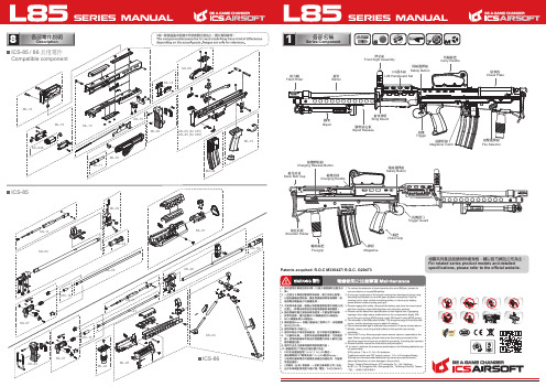
2-1裝BB彈方式Load BBs將彈匣上蓋依箭頭方向推開再倒入BB彈。
Open the cover to load BBs.建議使用 6mm BB彈。
6mm caliber BBs are recommended for optimum performance.依箭頭方向旋緊彈匣底下旋鈕,即可將BB彈順利送出。
To charge BB feed spring, please rotate the gear under the magazine.2-2裝卸彈匣Magazine Loadingand Unloading1.直接將彈匣插入彈匣插槽。
2.按壓退彈匣鈕即可將彈匣卸下。
1. Load the magazine directly into the magazine slot.2. Press the magazine catch to unload the magazine.2彈匣使用方式Magazine Attachment3可動部的說明Movable Parts1.將腳架固定板往後拉。
2.手抓住腳架使之併齊。
3.將腳架兩卡勾裝進護木上的定位孔。
4.放開固定板以收合腳架。
1. Pull the bipod releasing plate.2. Grab the bipod to align them together.3. Insert the hook on the stands into the positioning hole under the handguard.4. Release the releasing plate to store the bipod.1.將腳架固定板往後拉。
2.手抓住腳架使之併齊。
3.將腳架脫離護木定位孔。
4.放開腳架,腳架即可自然打開完成部署。
1. Pull the bipod releasing plate.2. Grab the bipod to align them together,3. Remove the stands from the positioning hole under the handguard.4. The bipod will be deployed automatically once you released it.3-1L86腳架調整L86 Store Bipod腳架收合To store the Bipod腳架佈署To deploy the Bipod3-2彈簧簧力調整Spring Adjustment1.將彈簧固定結合銷拉出。
英文安装说明书[1]
![英文安装说明书[1]](https://img.taocdn.com/s3/m/cb8afdda240c844769eaeefc.png)
2.4The mutual inductor secondary lines draw out with the4m㎡polyvinyl-chloride baling wire ,Is convenient for the wiring, gets "S1" on the wiring ear, "S2", "S3" and so on the mark..
2.5The entire mutual inductor soaks the insulating paint after the seasoning, after but dries, by guards against is affected with damp.
3.Techical Date
2.3On the post mutual inductor has the data plate and the polar symbol sign,symbolized on the sign the sign has "on" the inscription."On" indicated primary current in the mutual inductor the direction,Namely the expression works as when primary current by "on" end inflow, the secondary current then flows out from the S1 end after exterior load return route flows in the S2 end (or S3, S4, S5 end) .
C站JUE-85中文操作说明书 07-9-10
明进行了简单的翻译。如有不详之处,请参考原英文说明书,以原厂家英文说明书为准。
美特顿198534产品说明书

Eaton 198534Eaton Moeller® series Rapid Link - Reversing starter, 6.6 A,Sensor input 2, 230/277 V AC, AS-Interface®, S-7.A.E. for 62modules, HAN Q5, with manual override switchAllgemeine spezifikationEaton Moeller® series Rapid LinkReversing starter198534120 mm270 mm220 mm1.8 kg RoHSUL 60947-4-2CCCUL approvalIEC/EN 60947-4-2CEAssigned motor rating: for normal internally and externally ventilated 4 pole, three-phase asynchronous motors with 1500 rpm at 50 Hz or 1800 min at 60 Hz 4015081964093RAMO5-W202A32-512RS1Product Name Catalog NumberProduct Length/Depth Product Height Product Width Product Weight CertificationsCatalog Notes EANModel CodeParameterization: drivesConnect mobile (App) Parameterization: drivesConnectParameterization: FieldbusParameterization: KeypadDiagnostics and reset on device and via AS-InterfaceThermo-clickTwo sensor inputs through M12 sockets (max. 150 mA) for quick stop and interlocked manual operationManual override switchKey switch position HANDKey switch position AUTOElectronic motor protectionShort-circuit releaseThermistor monitoring PTCKey switch position OFF/RESETFor actuation of motors with mechanical brakeExternal reset possibleTemperature compensated overload protection CLASS 10 AIP65NEMA 12Class A10,000,000 Operations (at AC-3)10,000,000 Operations (at AC-3)Reversing starter0.3 A6.6 AIIIMotor starterASIAS-Interface profile cable: S-7.4 for 62 modules4000 VAC voltageCenter-point earthed star network (TN-S network) Phase-earthed AC supply systems are not permitted.Reversing starterDCFeatures Fitted with: Functions ClassDegree of protectionElectromagnetic compatibility Lifespan, electricalLifespan, mechanicalModelOverload release current setting - min Overload release current setting - max Overvoltage categoryProduct categoryProtocolRated impulse withstand voltage (Uimp) System configuration typeTypeVoltage typeVertical15 g, Mechanical, According to IEC/EN 60068-2-27, 11 ms, Half-sinusoidal shock 11 ms, 1000 shocks per shaftResistance: 10 - 150 Hz, Oscillation frequencyResistance: 6 Hz, Amplitude 0.15 mmResistance: 57 Hz, Amplitude transition frequency on accelerationResistance: According to IEC/EN 60068-2-6Max. 2000 mMax. 1000 mAbove 1000 m with 1 % performance reduction per 100 m -10 °C55 °C-40 °C70 °C< 95 %, no condensationIn accordance with IEC/EN 501780.3 - 6.6 A, motor, main circuit Adjustable, motor, main circuit6.6 A (at 150 % Overload)Maximum of one time every 60 seconds380 - 480 V (-15 %/+10 %, at 50/60 Hz)20 - 35 ms20 - 35 ms50/60 HzAC-53a 3 HP≤ 0.6 A (max. 6 A for 120 ms), Actuator for external motor brake230/277 V AC -15 % / +10 %, Actuator for external motor brake10 kA0 AType 1 coordination via the power bus' feeder unit, Main circuitMounting position Shock resistance Vibration AltitudeAmbient operating temperature - min Ambient operating temperature - max Ambient storage temperature - min Ambient storage temperature - max Climatic proofingCurrent limitationInput currentMains switch-on frequency Mains voltage tolerance Off-delayOn-delayOutput frequency Overload cycleRated frequency - min Assigned motor power at 460/480 V, 60 Hz, 3-phaseBraking currentBraking voltageRated conditional short-circuit current (Iq)Rated conditional short-circuit current (Iq), type 2, 380 V, 400 V, 415 VShort-circuit protection (external output circuits)47 Hz63 Hz6.6 A6.6 A0.09 kW3 kW0 kW3 kW400 V AC, 3-phase 480 V AC, 3-phase 50/60 Hz, fLN, Main circuit AC voltageCenter-point earthed star network (TN-S network) Phase-earthed AC supply systems are not permitted.0 V0 V0 V0 V0 V0 V24 V DC (-15 %/+20 %, external via AS-Interface® plug) 230/277 V AC (external brake 50/60 Hz)Connections pluggable in power section Specification: S-7.A.E. (AS-Interface®)Max. total power consumption from AS-Interface® power supply unit (30 V): 190 mANumber of slave addresses: 62 (AS-Interface®)010 m, Radio interference level, maximum motor cable lengthMeets the product standard's requirements.Meets the product standard's requirements.Rated frequency - max Rated operational current (Ie) at 150% overload Rated operational current (Ie) at AC-3, 380 V, 400 V, 415 V Rated operational power at 380/400 V, 50 Hz - min Rated operational power at 380/400 V, 50 Hz - max Rated operational power at AC-3, 220/230 V, 50 Hz Rated operational power at AC-3, 380/400 V, 50 Hz Rated operational voltage Supply frequencySystem configuration type Rated control supply voltage (Us) at AC, 50 Hz - min Rated control supply voltage (Us) at AC, 50 Hz - max Rated control supply voltage (Us) at AC, 60 Hz - min Rated control supply voltage (Us) at AC, 60 Hz - max Rated control supply voltage (Us) at DC - min Rated control supply voltage (Us) at DC - max Rated control voltage (Uc)ConnectionInterfacesNumber of auxiliary contacts (normally closed contacts)Number of auxiliary contacts (normally open contacts)Cable length10.2.2 Corrosion resistance10.2.3.1 Verification of thermal stability of enclosuresMeets the product standard's requirements.Meets the product standard's requirements.Meets the product standard's requirements.Does not apply, since the entire switchgear needs to be evaluated.Does not apply, since the entire switchgear needs to be evaluated.Meets the product standard's requirements.Does not apply, since the entire switchgear needs to be evaluated.Meets the product standard's requirements.Does not apply, since the entire switchgear needs to be evaluated.Does not apply, since the entire switchgear needs to be evaluated.Is the panel builder's responsibility.Is the panel builder's responsibility.Is the panel builder's responsibility.Is the panel builder's responsibility.Is the panel builder's responsibility.The panel builder is responsible for the temperature rise Generationentausch RA-SP zu RASP4.0Generation change from RA-MO to RAMO 4.0 Generationenwechsel RA-SP zu RASP5Generation change from RA-SP to RASP 4.0Generation change RAMO4 to RAMO5Elektromagnetische Verträglichkeit (EMV)Anschluss von Frequenzumrichtern an GeneratornetzeFirmware Update RASP 4.0Generationentausch RAMO4 zu RAMO5Generationswechsel RASP4 zu RASP5Generation Change RASP4 to RASP5Configuration to Rockwell PLC Rapid Link 5Configuration to Rockwell PLC for Rapid Link Generationentausch RA-MO zu RAMO4.0Generation Change RA-SP to RASP5MN040003_DEMN034004_DERapid Link 5 - brochureDA-SW-drivesConnect - installation helpDA-SW-USB Driver DX-COM-STICK3-KITDA-SW-drivesConnectDA-SW-Driver DX-CBL-PC-3M0DA-SW-drivesConnect - InstallationshilfeDA-SW-USB Driver PC Cable DX-CBL-PC-1M5Material handling applications - airports, warehouses and intra-logistics ETN.RAMO5-W202A32-512RS1.edzIL034084ZUDE | Rapid Link 5Sortimentskatalog Antriebstechnik-DE10.2.3.2 Verification of resistance of insulating materials to normal heat10.2.3.3 Resist. of insul. mat. to abnormal heat/fire by internal elect. effects10.2.4 Resistance to ultra-violet (UV) radiation10.2.5 Lifting10.2.6 Mechanical impact10.2.7 Inscriptions10.3 Degree of protection of assemblies10.4 Clearances and creepage distances10.5 Protection against electric shock10.6 Incorporation of switching devices and components10.7 Internal electrical circuits and connections10.8 Connections for external conductors10.9.2 Power-frequency electric strength10.9.3 Impulse withstand voltage10.9.4 Testing of enclosures made of insulating material10.10 Temperature rise Anmerkungen zur AnwendungBenutzerhandbücherBroschüreneCAD model Installationsanleitung InstallationsvideosKatalogeEaton Konzern plc Eaton-Haus30 Pembroke-Straße Dublin 4, Irland © 2023 Eaton. Alle Rechte vorbehalten. Eaton ist eine eingetrageneMarke.Alle anderen Warenzeichen sindEigentum ihrer jeweiligenBesitzer./socialmediacalculation. Eaton will provide heat dissipation data for thedevices.Is the panel builder's responsibility. The specifications for the switchgear must be observed.Is the panel builder's responsibility. The specifications for the switchgear must be observed.The device meets the requirements, provided the information in the instruction leaflet (IL) is observed.ramo5_v10.dwgramo5_v10.stpeaton-bus-adapter-rapidlink-reversing-starter-dimensions-002.eps eaton-bus-adapter-rapidlink-speed-controller-dimensions-003.eps eaton-bus-adapter-rapidlink-speed-controller-dimensions-002.eps eaton-bus-adapter-rapidlink-reversing-starter-dimensions-003.eps10.11 Short-circuit rating10.12 Electromagnetic compatibility 10.13 Mechanical function mCAD model Zeichnungen。
2.INMARSAT-C JUE85站操作说明
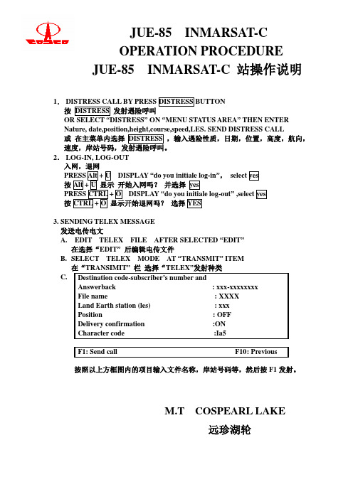
1. DISTRESS CALL BY PRESS DISTRESS BUTTON 按 DISTRESS 发射遇险呼叫 OR SELECT “DISTRESS” ON “MENU STATUS AREA” THEN ENTER Nature, date,position,height,course,speed,LES. SEND DISTRESS CALL 或 在主菜单内选择 DISTRESS ,输入遇险性质,日期,位置,高度,航向, 速度,岸站号码,发射遇险呼叫。 2. LOG-IN, LOG-OUT 入网,退网 PRESS Alt + U DISPLAY “do you initiale log-in”, select yes 按 Alt + U 显示 开始入网吗? 并选择 yes PRESS CTRL + O DISPLAY “do you initiale log-out” ,select yes 按 CTRL + O 显示开始退网吗? 选择 YES 3. SENDING TELEX MESSAGE 发送电传电文 A. EDIT TELEX FILE AFTER SELECTED “EDIT” 在选择“EDIT” 后编辑电传文件 B. SELECT TELEX MODE AT “TRANSMIT” ITEM 在“TRANSIMIT” 栏 选择“TELEX”发射种类 C. Destination code-subscriber’s number and Answerback : xxx-xxxxxxxx File name : XXXX Land Earth station (les) : xxx Position : OFF Delivery confirmation :ON Character code :Ia5 F1: Send call F10: Previous
设备安装技术要求-英文翻译

TECHNICAL SPECIFICATIONS FORINSTALLATION OF MECHNICAL EQUIPMENT1 HIGHLIGHTS OF CONSTRUCTION1.1 Construction preconditions of Equipment InstallationThe design document and other technical documents are all ready, the constructiondrawings have been jointly checked up, technique clarification and necessarytechnical training shall have been accomplished.Relative foundation and trench work shall have been finished,the concrete strengthshall not be lower than 75% of design strength.1.2 Acceptance of Equipment Foundation1.2.1 Acceptance of Civil DataQuality certificate.Survey Record and other construction data shall be ready.1.2.2 Foundation checkingThe position, geometry dimension and quality requirements of the equipmentfoundation shall comply with the construction drawings and the Code forConstruction and Acceptance of Concrete Structures (GB50204-92).Both the foundation surface of the equipment and the reserved holes of anchor boltsshall be cleaned up, the screw thread and the nut of the embedded anchor bolt shallbe kept in good condition.The allowable tolerance of equipment foundation dimensions refer to table 1:Table 11.3 Unpacking Inspection of EquipmentUnpacking inspection of equipment shall be executed under the supervision of theOwner’s personnel, Contractor shall inspect the following items:Appearance , quantity, specification and model of the equipmentPacking list and other technical dada.During the inspection Contractor shall keep all the records.Equipment , spare parts and special tools shall be carefully kept.1.4 Installation of Equipment1.4.1 Positioning and Aligning of EquipmentThe baseline of installation shall be designated accord with construction drawing andrelating axis, edge line or elevation line before equipment positioning.The allowable tolerance of of the distance from plane installation bench mark toactual foundation axis or between actual shop wall axis and edge line is ±20mm.Refer to Table 2 for the allowable tolerance of plane position and elevation of thepositioning plane, line or point to bench mark:Table2The allowable tolerance of equipment installation refers to table 3: Table 3D2000,±5Center-to-centerD2000,±10Measure alongcircumference of baseD2000,10D>2000,151.4.2 Anchor BoltThe Anchor bolt in the reserved hole shall accord with the requirement ofconstruction drawing and design document; the requirement below must be followedif no other special instructions are available:(1) Anchor bolt shall be vertical in reserved hole free of inclining.(2) The distance between any part of anchor bolt to the hole wall shall be largerthan 15mm, and the bolt end shouldn’t touch hole bottom.(3) The oil dirt and oxidized surface of anchor bolt shall be clear away, a littlegrease shall be applied to the screw thread of the anchor bolt.(4) There shall be no distance between the nut and the gasket, and so are thegasket and the pedestal of the equipment.(5) Bolt shall extend out of nut after nut fastening; the exposed length is about1/3-2/3 of the diameter value of the bolt.(6) The anchor blot shall be fastened while concrete strength in reserved reachesmore than than 75% designed value, the fastening strength shall be evenly.1.4.3 Iron ShimThe shim size for level adjusting of equipment shall accord with the requirement ofconstruction drawings or technical documents.The common wedge shim and flat shim shall be selected according to Appendix 5 ofthe Construction & Acceptance Criterion of Machine & Equipment Installation Works(GB50231-98).1.4.4 GroutingThe grouting between the foundation and pedestal of the equipment/the reservedhole of the anchor bolt shall comply with the Code for Construction and Acceptanceof Concrete Structures (GB50204-92).The grouting place shall be cleaned up before grouting. The concrete grade used forgrouting is one grade higher than that used for foundation or ground. Groundingshouldn’t make anchor bolt inclined or affect installing precision of the equipment.The thickness of grouting layer shall accord with design requirement, commonly notless than 25mm.The outer forms shall be laid before grouting, the distance of outer forms from outeredge of equipment base shouldn’t less than 60mm; Float coat shall be applied to thesurface after removal of forms.The inner forms shall be laid when complete grouting is not needed under equipmentbase and grouting layer would bear load of equipment.1.4.5 Assembly of EquipmentThe assembly of equipment shall accord with the requirement of constructiondrawings, technical documents of manufacturer and Code for Construction &Acceptance of Machine & Equipment Installation Works (GB50231-98).Before the equipment assembly, the Contractor shall be familiar with the equipmentstructure and the technical requirements of equipment assembly. Recheck andcleaning treating on match dimension, relating precision, match face and sliding faceof assembly parts shall be done, and the assembly shall be performed according tomarks and assemble sequence.As to equipment or parts have inner cavity, careful check and clearance must bedone before concealing avoid any foreign substance contained in it.As to oil tank or water tank that difficult to disassembly, check and fix, leakageexamination must be done before assembly.1.4.6 Installation of Equipment AccessoriesThe installation of tower and inner parts of equipment shall accord with therequirement of construction drawings and Code for Construction & Acceptance ofMachine & Equipment Installation Works (GB50231-98).The installation of inner parts of pump shall accord with the requirement ofconstruction drawings and Construction, Code for Construction and Acceptance ofCompressor, Fan and Pump Installation Works (GB50275-98).The installation, pressure testing of accessory pipe shall accord with the requirementof construction drawings and Code for Construction and Acceptance of IndustrialPiping Works (GB50236-98).The installation of accessory ladder, platform shall accord with the requirement ofconstruction drawings and Code for Construction and Acceptance of Steel StructureWorks (GB50205-95).1.4.7 Equipment TestAfter the installation completed, all the welding seams of pressure vessel shall bechecked according to the Assessment on Welding Technology of Pressure Vessel(JB4708-92) and make record.Pressure experiment shall be performed to pressure container accord withconstructing instructions and design requirement after installation.The pressure & leakage test shall be executed according to the ConstructionExplanation and the Design Requirements after the installation of stove type andfamiliar equipments that have water double layer.1.4.8 Cleaning and Purging of EquipmentWhen the installation of pump equipment completed, cleaning and purged of suchequipment must be carried out according to construction drawings and Construction,Checking and Construction, Code for Construction and Acceptance of Compressor,Fan and Pump Installation Works (GB50275-98).The cleaning and purging of static equipment must be performed after installationaccording to construction drawings and Code for Construction & Acceptance ofMachine & Equipment Installation Works (GB50231-98).1.4.9 Test-run of EquipmentThe conditions, contents and procedure shall be ready before equipment test-run, asspecified in Code for Construction & Acceptance of Machine & EquipmentInstallation Works (GB50231-98).Make good test-run record during the test-run operation.After test-run of equipment, turn off power supply, drain out water and vent air andclean as per Code for Construction & Acceptance of Machine & EquipmentInstallation Works (GB50231-98).1.4.10 Taking-over, Inspection and Acceptance of the Equipment Installation WorksAfter all the working procedure of equipment have finished, the Contractor shall packup all the construction documents and perform inspection & acceptance of theEquipment Installation Works under the supervision of relative personnel if thetest-run of equipment is successful and meet the requirements of Design and Relative Specifications.At last the Contractor shall go through the formalities of taking-over procedure.ATTACHED ILLUMINATION:This Standard Is Kept By Technique Department.This Standard Was Prepared By Construction Management Department.THE MAIN DRAFTSMAN OF THIS STANDARD:Xu QingChecked by :Xu Xingguo / Wu BenlunApproved by :。
E60E68+连接维护说明书

2.安装相关事项
注意
控制单元·操作板请安装在不可燃物上。直接安装在可燃物上,或安装在可燃物附近,可能会导致火灾。
请务必要遵守安装方向上的要求。
请不要安装、运转损伤、缺少部件的制单元、操作板。
请注意不要让螺丝·金属片等导电性异物及油等可燃性异物混入控制单元·操作板内部。
控制单元·操作板为精密设备,所以请注意不要让其跌落、受到强烈冲击。
3.2.1 操作箱的外形轮廓与尺寸 ............................................................................................................................................8 3.2.2 操作箱的散热对策 ......................................................................................................................................................10 3.3 防干扰对策 ...............................................................................................................................................................................11 3.3.1 机架接地(FG)的连接 .............................................................................
全自动订书机英文说明书

CB5000 Vehicular Baler Operation InstructionSafety Tips1、Please read this specification carefully before operation.2、Lowered cab should cover door closed when stop the machine, meanwhile steel grasp machine is placed on the bracket, and cut off all the power.3、Equipment shall not be maintained in the process of work. Also the worker should not stand on the fuselage and should not hand foot and other parts of body must not be placed in the door between the cover and the box body.4、If you need in packaging case for cleaning or maintenance, the device should be in a state of downtime, and the door covers is fixed in the fully open position, cut off the equipment power rear can be carried out. When piping system leak or failure occurs, please stop immediately, to run after trouble shooting. Equipment of diseased or overload operation is prohibited5、Remove the hydraulic valve replacement seals and check the pipeline, the pressure in the system, please state, avoid when remove the high pressure oil made hydraulic valve and pipeline damage in the body.6、The hydraulic nonprofessionals should not adjust the hydraulic system of hydraulic valve, avoid the equipment cannot run normally or damage to the hydraulic valves .7、When equipment running , it shall not live without operator in front of he operation stage .8、According to using frequency , you should often check the oil cylinder installation area and other connection key parts , may not have a screw loose or pin off accident hidden trouble.9、When it in work state, you must raise cab.10、If you can’t solve the problems, lease contact our nearest office, also can find our after-sales service department directly .Catalogue1. Usage and features------------------------------------------------------------ 42. General structure and working principle ---------------------------------- 43. Mainly technical specification------------------------------------------------ 64. General breakdown and solution ------------------------------------------- 75. Maintenance and serving ----------------------------------------------------- 86. Overall drawing ------------------------------------------------------------------ 91. Usage and features1) UsageThe equipment is mainly for baling low-carbon light and life scrap steel; scrap cars; light metal structural parts with steel material to bales for furnace. It is an ideal machine for steel factories; non-ferrous metal smelting industry; precision casting industry and raw materials factories.2)Features1、This machine with big volume; large open areas; amount of feeding capacity; high efficiency. It is very convenient for processing large shape materials, especially in gather feeding and capture scrap.2、Hydromechatronics control, easy to learning, and intuitive operation and convenient.3、PLC control, high reliability and easy for maintenance.4、Hydraulic drive; working smooth; high efficiency.2. General structure and working principle1). General structureMainly composed of mechanical systems (main machine), power systems, hydraulic systems. (see schematic layout)〈1〉、Mechanical systemBe composed of press box; hydraulic press cylinder and other assistant component. (see main machine structure diagram)1.Press boxBe made up of material body; level 1 lid; level 2 lid; main cylinder components. Material body is composed of pedestal, level 1 lid, level 2 lid, there are ware plates on it. Part of ware plates are import DILLINDUR which made by Germany. Compressed scrap material by wrapped work of level 1 lid and lever 2 lid so that increase density. After that, two main press cylinder will continues to compress scraps into blocks.2. Hydraulic cylinder is made up of main press cylinder; level 1 lid cylinder; lever 2 lid cylinder. Mainly turn hydraulic power into mechanical power, the cylinder mainly drive all parts of action, in order to complete compression and pressed actions.(1) Main press cylinders, totally two sets which installed on the bottom of press box. Piston rod connection with head of press plates to compress scraps inside by advance and forward of main press cylinders.(2). Level 1 lid cylinders, totally 3 sets which installed on the side of press box to compress scraps by piston rod advance action when scraps to be packaged.(3). Level 2 lid cylinder, totally 3 sets which installed on the other side of press box to complete open and close action for press lid by piston rod advance action and back action.The above are double acting single piston rod structure, and the liner with piston and seals, the cylinder body to form two oil chambers and small cavity. When the high pressure oil of the front chamber or the rear chamber, the push rod and piston within the cylinder for reciprocating liner motion, thereby driving the workpiece movements. Cylinder brim with guide sleeve, the above is also equipped with a ring, as the piston rod supporting, guiding and sealing.<2> The power system is composed of main engine circuit, engine start/stop control circuit and the PLC input and output control circuit, external line,pressing stroke control device, external stroke control system etc..<3> The hydraulic system, is composed of a hydraulic oil tank, hydraulic pump, valve, hydraulic station pipeline system, is the host of the central control system.<4> Pipeline system is connected to the host (Mechanical Systems) and between the hydraulic system, hydraulic oil for transfer.2). working principle and attention(1) working principle and processThe two main oil cylinders backhaul in place, the first and second level pressing door r\ opening, the operator use the grab machine to package materials into the pressing box in the cab. The first level pressing door close, the second level pressing door close , forming clips action, two main pressing oil cylinder forward, the material to the middle pressed into blocks. Then return in place, the first and second level pressing door open, the operator remove the bale by the grab, equipment repeat the above action until the end of the work.(2) attention1.The scrap’s density and rigidity greatly is not allowed to add too much, otherwise it will make the first and second pressing door is not in place, thus affecting the machine, or even destroy the machine.2.Mixed with pressure vessel, flammable items are not allowed in the waste3.This machine belongs to the hydraulic equipment, prolong the service life of hydraulic components, please ensure the cleanliness of the system.Technical ParametersGeneral failures and exclusionDuring shearing time,If abnormal situation be founded,you should stop working,After waiting for troubleshooting to continue shear, in use process may be the cause of theProblems in the practical work, may be caused by many factors, so in the event of a failure, should be carefully observed and carefully analyze the causes, and then start out.MaintenanceThe correct use of machinery and equipment, seriously implement the system of maintenance and strictly abide by rules of safe operation, is extending the service life of the machine, improve production efficiency and ensure the necessary conditions for production. Therefore, recommend that users establish a maintenance and safe operating procedures, operating personnel in addition to the machine should be familiar with the structure and operating procedures, also must pay attention to the following points:1.The oil in oil tank should pass strict filtering, and often should keep enough oil.2.Once every half a year should clean and replace the oil , but the first oil change time should be no more than three months, the oil can pass strict filtered using it again.3.Lubricating oil lubrication each machine should be according to the requirements listed. Before work and after work every day need to inspect again to check whether the machine is normal.4.Without learning, don't understand the machine structure, performance and operatingrules cannot do STH without authorization to start the machine.5.When the machine appear serious leak or abnormal phenomena occurred during work, you should immediately stop, analysis of causes and troubleshooting, shall not be forced to run .6.Machine in the process of operation or packaging, shall not carry out repair or touch themoving parts by hand , it is forbidden to use hands or feet press materials in feed box. 7.To adjust the valve, pressure gauge, must be conducted by experienced technical workers, in case of malfunctioning of a pressure gauge, should immediately check the repair or replacement of the new table.8.Sealing element should be changed regularly, if any, should be replaced immediately.。
ZF-815安装使用说明书 英文版
Installation Instruction Booklet1. Installation notes(1). To laying water pipes, it should in accordance with the specification of this Instructionbooklet.(2). There must be floor drain where you want to install the faucet.(3). The installation of faucet should after the decoration of the room, due to the painting andother gas would cause faucet surface to be corrosive.(4). Before installation, you should connect to water and need to clean the sand and other junk inthe pipe.(5). Please blind with Thread seal tape in the connecting part of thread and tighten with spanner.Using a soft cloth on wrench jaw in order to avoid tooling mark on the faucet. (Caution: if the pipe thread does not match, please check the reason first, do not force to tighten in order to avoid the damage of faucet accessory).(6). After finishing installation, please check all the fastness of all the connecting part, connectthe water, open and close repeatedly. Then check and ensure there is no leakage problem of the connecting part.(7). Please forward the installation instruction booklet to customers.2. Precaution for use(1). This product should be used in the following condition: water pressure 0.1-1.0Mpa, watertemperature 4-90℃.(2). Do not hang the heavy on the faucet.(3). If there is no water when you open the faucet, please remember to close the faucet(especially during cutting off the water supply, rooms under decorating or temporary out)(4). Please use neutral detergent and soft cloth to clean the faucet surface to ensure its bright.(5). When the room temperature is under 0 ℃, there is necessary to take anti freezing measuressuch as keep the room warm, close the windows and so on, in order to avoid to be frost cracking.(6). When you are doing cleaning or taking shower, please open the cold water first, then changeto hot water, and wait until the water temperature is fine for you. Please do not touch the hot water part of the faucet to avoid scalding.(7).Non professionals please do not disassemble this product without authorization.3. Installation instruction(1). Insert the faucet and panel into the sink.(2).Hand tighten both the locknuts onto the shanks from under the sink(3).Using the other locknuts and washers to connect the inlet shanks with pipe and hand tighten the locknuts or connect inlet shanks with the hoses directly without the locknuts and washers.。
SENLAN(森兰)变频器SB80系列说明书 免费下载

I感谢您购买SB80A/B/C ProDrive 系列工程型矢量控制变频器。
该产品主要用于对三相感应电机的转速和转矩进行控制。
本手册提供用户安装配线、参数设定、日常维护、故障诊断和排除方法等内容。
在安装、设置、运行和维护变频器之前,请务必详细阅读本产品用户手册的全部内容,熟记变频器的有关知识、安全注意事项,确保正确使用并充分发挥其优越性能。
本产品采用的产品技术规范可能发生变化,内容如有改动,恕不另行通知。
本产品用户手册应妥善保存至变频器报废为止。
如有需要,成都希望森兰变频器制造有限公司将为客户提供全方位的技术支持。
本手册根据与安全相关的内容,使用下列标记。
附有安全标记的内容,请务必遵守。
错误使用或不按要求操作,有造成人身伤亡的危险。
不按要求操作,可能造成中等程度伤害或轻伤,或造成变频器或机械系统等财产损失。
不按要求操作,可能造成系统工作不正常,严重时会引起变频器或机械损坏。
实用的说明和补充内容,特别是一些涉及特殊性能的调试要点和常见错误。
防止电击!! z 必须将变频器的接地端子可靠正确接地(对地电阻≤10Ω),否则有触电的危险。
z 上电前必须将变频器盖板盖好,否则有触电和爆炸的危险。
z 当输入电源接通时不能打开前端盖板;通电情况下,不要用手触摸控制端子,否则有触电的危险。
z 确认输入电源处于完全断开的情况下,才能进行配线作业,否则有触电的危险。
z 应在断开电源10分钟后进行维护操作,确认充电指示灯彻底熄灭且正负母线电压在36V 以下,否则有触电的危险。
z 不要用潮湿的手操作变频器,否则有触电的危险。
防止火灾!!z 不能将变频器安装在有易燃物或靠近易燃物的地方,否则会有发生火灾的危险。
z 不要安装在含有可燃性气体的环境里,否则有引发爆炸的危险。
z 当变频器发生故障时应立即排除故障原因,否则会有发生火灾的危险。
z 不要在直流端子DC(+)、DC(-)之间直接连接制动电阻,否则有发生火灾的危险。
防止损坏变频器!!z 输入电源端子电压不能超出额定电压范围,否则将导致变频器损坏。
METRACLIP 85 电压多功能仪说明书

Start GuideClamp Multimeter METRACLIP 85 EnglishYou have just acquired an METRACLIP 85 clamp multimeter and we thank you.For best results from your device :• read this user manual attentively, • observe the precautions for its use.Meanings of the symbols used on the deviceDanger. The operator agrees to refer to this data sheet whenever this dangersymbol is encountered.Application or withdrawal authorized on uninsulated or bare conductors atdangerous voltages.9 V battery.The CE marking indicates compliance with European directives.Double insulation or reinforced insulation.Selective sorting of wastes for the recycling of electrical and electronic equipment within the European Union.In conformity with directive DEEE 2002/96/EC: this equipment must not betreated as household waste.AC – Alternating current.AC and DC – Alternating and direct current.Earth.Risk of electric shock.English Clamp Multimeter METRACLIP 85PRECAUTIONS FOR USEThis device complies with safety standards IEC-61010-1 and 61010-2-032 for voltages of 1000V in category III or 600V in category IV at an altitude OF less than 2000m, indoors, with a degree of pollution not exceeding 2.These safety instructions are intended to ensure the safety of persons and proper operation of the device. If the tester is used other than as specified in this data sheet, the protection provided by the device may be impaired.▪The operator and/or the responsible authority must carefully read and clearly understand the various precautions to be taken in use.▪If you use this instrument other than as specified, the protection it provides may be compromised, thereby endangering you.▪Do not use the instrument in an explosive atmosphere or in the presence of flammable gases or fumes.▪Do not use the instrument on networks of which the voltage or category exceeds those mentioned.▪Do not exceed the rated maximum voltages and currents between terminals or with respect to earth.▪Do not use the instrument if it appears to be damaged, incomplete, or not properly closed.▪Before each use, check the condition of the insulation on the leads, housing, and accessories. Any element of which the insulation is deteriorated (even partially) must be set aside for repair or scrapped.▪Use leads and accessories rated for voltages and categories at least equal to those of the instrument. If not, an accessory of a lower category lowers the category of the combined Clamp + accessory to that of the accessory.▪Observe the environmental conditions of use.▪Do not modify the instrument and do not replace components with "equivalents". Repairs and adjustments must be done by approved qualified personnel.▪Replace the battery as soon as the symbol appears on the display unit. Disconnect all cords before opening the battery compartment cover.▪Use personal protective equipment when conditions require.▪Keep your hands away from the unused terminals of the instrument.▪When handling the test probes, crocodile clips, and clamp ammeters, keep your fingers behind the physical guard.▪As a safety measure, and to avoid repeated overloads on the inputs of the device, we recommend performing configuration operations only when the device is disconnected from all dangerous voltages.Clamp Multimeter METRACLIP 85 EnglishMEASUREMENT CATEGORIESDefinitions of the measurement categories :CAT II: Circuits directly connected to the low-voltage installation.Example: power supply to household electrical appliances and portable tools.CAT III: Power supply circuits in the installation of the building.Example: distribution panel, circuit-breakers, fixed industrial machines or devices.CAT IV: Circuits supplying the low-voltage installation of the building. Example: power lines, meters, and protection devices.1 PRESENTATIONItem Designation1Jaws with centring marks (see connection principles)2 Physical guard3 Switch4 Function keys5 Display unit6 Terminals7 TriggerEnglish Clamp Multimeter METRACLIP 85 1.1 THE SWITCHThe switch has six positions. To access the , , , , , functions, set the switch to the desired function. Each setting is confirmed by an audible signal. The functions are described in the table below.1.2 THE KEYS OF THE KEYPAD1 2 34 5 6Item Function1 OFF mode – Switches the clampmultimeter off2 AC, DC voltage measurement (V)3 Continuity testResistance measur ement ΩDiode test4 AC, DC current measurement (A)5 Temperature measurement (°C/°F)6 Adapter functionItem Function1 Storage of values, disabling of displayZero correction A DCCompensation of the resistance of the leadsin the continuity and ohmmeter function2 Selection of the type of measurement (AC,DC)3 Activation or de-activation of thebacklightingof the display unit4 Activation or de-activation of the MAX/MINmodeActivation or de-activation of the INRUSHmode in A5 Frequency measurements (Hz)6 Activation of ΔREL mode – Display ofdifferential and relative valuesClamp Multimeter METRACLIP 85 English1.3DISPLAY51.3.1The symbols of the display unitSymbol DesignationAC Alternating current or voltage DC Direct current or voltage∆REL Relative value, with respect to a reference ∆RefReference valueStorage of the values and hold of the display M ax Maximum RMS value Min Minimum RMS value V Volt Hz Hertz A Ampere % Percentage ΩOhmItem Function1Display of the modes selected (keys)2Display of the measurement value and unit3 Display of the MAX/MIN modes4 Type of measurement (AC or DC) 5Display of the selected modes (switch)6Spent battery indicationEnglish Clamp Multimeter METRACLIP 85m Milli- prefix kKilo- prefixCompensation of the resistance of the leadsContinuity testDiode testPermanent display (automatic switching off de-activated)Spent battery indicatorThe O.L (Over Load) symbol is displayed when the display capacity is exceeded.1.1THE TERMINALSThe terminals are used as follows:1 2Item Function 1 Cold terminal (COM) 2Hot terminal (+)Clamp Multimeter METRACLIP 85 English22 USE2.1 COMMISSIONINGInsert the battery supplied with the device as follows:1. Using a screwdriver, unscrew the screw of the battery compartment cover (item 1) onthe back of the housing and open it.2. Place the battery in the compartment (item 2), taking care to get the polarities right.3. Close the battery compartment cover and screw it to the housing.2_Ed1_1/212。
飞利浦电视85系列用户手册说明书

用户手册43PUS851750PUS851758PUS851765PUS8517Register your product and get support at /TVsupport内容1 主屏幕4 1.1 主屏幕和频道4 1.2 主屏幕更新4 1.3 应用程序和飞利浦电视系列41.4 打开主屏幕42 设置6 2.1 阅读安全说明6 2.2 电视支架和壁挂安装6 2.3 摆放提示6 2.4 电源线6 2.5 天线62.6 圆盘式卫星天线73 遥控器8 3.1 键概述8 3.2 将遥控器与电视配对10 3.3 语音搜索10 3.4 红外传感器11 3.5 电池113.6 清洁114 打开和关闭12 4.1 开机或待机124.2 电视上的按键125 频道13 5.1 安装频道13 5.2 频道列表13 5.3 频道列表排序13 5.4 观看频道13 5.5 收藏频道16 5.6 文本/图文电视175.7 互动电视186 频道安装19 6.1 卫星安装19 6.2 天线安装216.3 频道列表复制237 连接设备25 7.1 关于连接25 7.2 带智能卡的 CAM - CI+26 7.3 家庭影院系统 - HTS26 7.4 智能手机和平板电脑27 7.5 蓝光光盘播放机27 7.6 蓝牙27 7.7 耳机28 7.8 游戏控制台28 7.9 USB 硬盘驱动器28 7.10 USB 键盘29 7.11 USB 闪存盘29 7.12 照相机30 7.13 摄像机30 7.14 电脑308 连接 Android TV32 8.1 网络和互联网32 8.2 Google 帐户338.3 飞利浦电视系列应用程序339 应用程序35 9.1 关于应用程序35 9.2 Google Play35 9.3 启动或停止应用程序36 9.4 锁定应用程序36 9.5 管理应用程序379.6 存储3710 互联网38 10.1 启动互联网3810.2 互联网选项3811 快捷菜单3912 来源40 12.1 切换设备40 12.2 电视输入的选项40 12.3 设备名称和类型4012.4 重新扫描连接4013 网络41 13.1 网络4113.2 蓝牙4114 设置42 14.1 图片42 14.2 声音44 14.3 流光溢彩设置48 14.4 环保设置49 14.5 一般设置49 14.6 时钟、区域和语言设置51 14.7 Android 设置52 14.8 通用接入设置5214.9 锁定设置5215 视频、照片和音乐54 15.1 来自电脑或 NAS54 15.2 收藏夹菜单54 15.3 最流行菜单和最后播放菜单54 15.4 来自 USB 连接54 15.5 播放视频54 15.6 查看照片5515.7 播放音乐5616 电视指南58 16.1 您需要执行的操作58 16.2 电视指南数据5816.3 使用电视指南5817 录制和暂停电视60 17.1 录制6017.2 暂停电视6118 智能手机和平板电脑6318.1 飞利浦电视遥控应用程序6318.2 Google Cast6319 游戏64 19.1 您需要执行的操作64 19.2 游戏手柄64 19.3 通过游戏控制台玩游戏6419.4 游戏控制条6420 流光溢彩65 20.1 流光溢彩风格65 20.2 关闭流光溢彩65 20.3 流光溢彩设置65 20.4 Lounge Light 模式65 20.5 晨起闹钟66 20.6 Ambisleep66 20.7 流光溢彩扩展6620.8 Aurora6721 精品选择69 21.1 关于精品选择69 21.2 电视现有应用程序6921.3 随选视频6922 Freeview Play71 22.1 关于 Freeview Play7122.2 使用 Freeview Play7123 Netflix7224 Alexa73 24.1 关于 Alexa7324.2 使用 Alexa7325 软件74 25.1 更新软件74 25.2 软件版本74 25.3 自动软件更新74 25.4 查看软件更新历史记录74 25.5 开源软件7525.6 开源许可证7526 规格76 26.1 环境76 26.2 功率76 26.3 操作系统76 26.4 接收76 26.5 显示屏类型77 26.6 显示屏输入分辨率77 26.7 连接77 26.8 声音7726.9 多媒体7727 帮助与支持79 27.1 注册电视79 27.2 使用帮助79 27.3 故障检修79 27.4 在线帮助8127.5 支持和维修8128 安全与保养82 28.1 安全82 28.2 屏幕保养8329 使用条款84 29.1 使用条款 - 电视84 29.2 使用条款 - 智能电视8429.3 使用条款 - 飞利浦电视系列8430 版权85 30.1 HDMI85 30.2 HEVC 高级85 30.3 杜比视界和 Dolby Atmos85 30.4 DTS-HD85 30.5 DTS Play-Fi85 30.6 Wi-Fi Alliance85 30.7 Kensington8530.8 其他商标8631 关于第三方提供的服务和/或软件的免责声明87索引881主屏幕1.1主屏幕和频道要充分享受 Android电视的益处,请将电视连接至互联网。
杰特锐机械工具 GHB-1340A 和 BDB-1340A 头部装配指南说明书

Parts ListGHB-1340A / BDB-1340A(GHB-1340A shown with optional stand 321443K)JET P.O. BOX 1349 Phone: 253-351-6000 WMH Tool Group Auburn, WA 98071-1349 Fax: 1-800-274-6840 **********************M-321357A 06/02Table of ContentsTable of Contents (2)BDB-1340A Headstock Assembly I........................................................................................................3-4 BDB-1340A Headstock Assembly II.......................................................................................................5-6 BDB-1340A Headstock Assembly III......................................................................................................7-8 GHB-1340A Headstock Assembly I.....................................................................................................9-10 GHB-1340A Headstock Assembly II..................................................................................................11-12 GHB-1340A Headstock Assembly III.................................................................................................13-14 Bed Assembly I.................................................................................................................................15-17 Bed Assembly II................................................................................................................................18-19 Gear Assembly I...............................................................................................................................20-21 Gear Assembly II..............................................................................................................................22-23 Gear Assembly III.............................................................................................................................24-25 Apron Assembly I..............................................................................................................................26-27 Apron Assembly II.............................................................................................................................28-29 Apron Assembly III (30)Micro Carriage Stop Assembly (31)Top Slide, Tool Post, Saddle and Cross Slide Assembly I.................................................................32-33 Top Slide, Tool Post, Saddle and Cross Slide Assembly II................................................................34-35 Tailstock Assembly I.........................................................................................................................36-37 Tailstock Assembly II........................................................................................................................38-39 Follow Rest.. (40)Steady Rest......................................................................................................................................41-42 Additional Parts. (43)Additional Electrical Components (43)Electrical Schematic - GHB-1340A (44)Electrical Schematic - BDB-1340A (45)Wiring Photo GHB-1340A (46)Wiring Photo BDB-1340A (47)Index PartNo. No. Description Size Qty.1..........04101B........................Headstock Casting.. (1)10........TS-1482021.................Hex Socket Cap Screw..........................M6 x 12.. (4)11........04501A........................Inlet Plug. (2)13........BDB1340-H13..............Oil Sight Glass.. (2)14........TS-1503031.................Hex Socket Cap Screw..........................M6 x 12.. (3)15........TS-1490081.................Hex Cap Bolt.........................................M8 x 45.. (2)15-1.....TS-1540061.................Nut........................................................M8 (2)17........BDB1340-H17..............Screw....................................................1/8”.. (2)55........04733B........................Knob.. (1)83........04310...........................Cover. (1)84A......04723A........................Cover Hinge (1)84B......04723B........................End Cover Hinge. (1)85........04705...........................Strut (1)86........BDB1340A-02118A......Arm (1)87........TS-1523031.................Set Screw..............................................M6 x 10.. (2)88........04725B........................Plunger. (1)89........BDB1340-H89..............Cap Nut (1)90........04734B........................Spring Sleeve (1)91........BDB1340-H91..............Spring....................................................1x9x50 (1)92........04721...........................Idle Shaft. (2)93........BDB1340-H93..............Oil Nipple. (2)94........04719...........................Gear......................................................1.5m26T. (1)95........04303...........................Bushing (2)96........04720...........................Gear......................................................1.5m21T. (1)97........BDB1340A-02717A......Output Shaft.. (1)98........BB-6202ZR..................Ball Bearing...........................................6202ZR.. (2)99........BDB1340A-H99............Key........................................................5 x 5 x 50.. (1)100......TS-1540081.................Hex Nut.................................................M12.. (1)101......BDB1340-H93..............Oil Nipple. (1)102......04716...........................Spacer.. (1)103......04119A.........................Flange.. (1)104......BDB1340A-02718A......Gear......................................................1.5m50T. (1)105......GH1340A-05735..........Gear......................................................1.25m32T.. (1)............32A5726A....................Gear......................................................1.25m42T.. (1)............BDB1340A-32A5726A..Gear......................................................1.25m44T.. (1)106......BDB1340-H106............Washer. (1)107......04714...........................Bolt. (1)120......TS-1482021.................Cap Screw.............................................M6 x 12.. (4)121......BDB1340A-02722A......Stud (1)122......BDB1340A-02305A......End Cover.. (1)123......BDB1340-H123............Knob.. (1)124......BDB1340-H124............Knob.. (2)125......04724...........................Cover. (1)127......BDB1340-H127............Rubber Mat. (1)128......TS-1503081.................Hex Socket Cap Screw..........................M6 x 35.. (2)129......BDB1340-H129............C-Clip....................................................8 (1)133......BDB1340A-H133..........C-clip for Shaft.......................................19. (1)134......BDB1340A-02124........Spacer.. (1)135......BDB1340A-H135..........Plug.......................................................5 (1)136......BDB1340A-H136..........Sign Plate (1)137......BDB1340A-H137..........Half Round Cap Screw..........................M3x50. (8)138......BDB1340A-H138..........Sign Plate (1)Index PartNo. No. Description Size Qty.2..........TS-1503051.................Hex Socket Cap Screw..........................M6 x 20.. (4)3..........BB-30212.....................Taper Roller Bearing..............................60 x 110 x 22 (1)4..........BDB1340-H4................Oil Seal..................................................PG60 x 80 x 12.. (1)5..........OS-709012...................Oil Seal..................................................SG70 x 90 x 12.. (1)6..........BB-30211.....................Taper Roller Bearing..............................55 x 100 x 21.. (1)7..........TS-1503041.................Hex Socket Cap Screw..........................M6 x 16.. (4)18........04701...........................Spindle..................................................D1-4. (1)19........BDB1340-H19..............Key........................................................8 x 7 x 18.. (1)20........BDB1340-H20..............Key........................................................6 x 6 x 16.. (1)21........04102...........................Bearing Cover (front). (1)22........BDB1340-H22..............Oil Seal..................................................75 x 100 x 12.. (1)23........BDB1340-H23..............O-Ring...................................................125 x 3.1 (1)25........BDB1340-H25..............Shaft Pin................................................3 x 18.. (1)26........BDB1340-H26..............Spring....................................................0.8 x 11 x 18. (1)27........04703...........................Pin.. (1)28........04702...........................Nut. (1)29........04117A.........................Gear......................................................2m74T (1)30........04116...........................Pulley (1)31........TS-1523031.................Set Screw..............................................M6 x 10.. (2)32........04302...........................Bushing (1)33........04301...........................Bushing (1)34........04115...........................Gear......................................................2m44T (1)35........04114...........................Spacer.. (1)36........TS-1524021.................Set Screw..............................................M8 x 6. (1)37........BDB1340-H37..............O-Ring...................................................60 x 3.1.. (1)38........04112A.........................Spacer.. (1)39........04113...........................Bearing Cover (rear).. (1)40........BDB1340-H40..............Oil Seal..................................................W60 x 80 x 8 (1)41........BDB1340-H41..............O-Ring...................................................110 x 3.1 (1)42........04713...........................Gear......................................................1.5m50T. (1)43........04743...........................Locking Nut (2)110......04729...........................Cam.. (3)111.......04741...........................Pin.. (3)112......BDB1340-H112............Spring....................................................0.6 x 4 x 16.. (3)113......TS-1504041.................Hex Socket Cap Screw..........................M8 x 18.. (3)130......BDB1340-H130............O-Ring...................................................55 x 3.1.. (1)131Index PartNo. No. Description Size Qty.8..........TS-1524021.................Set Screw..............................................M8 x 10.. (1)15-1.....TS-1540061.................Nut........................................................M8 (1)44........04704...........................Eccentric Shaft. (1)45........04103A........................Bushing (1)46........04109A........................Gear......................................................2m52T, 2m22T (1)47........TS-1523011.................Set Screw..............................................M6 x 6. (1)48........04111A.........................Bushing (1)49........04110...........................Moving Arm (1)50........TS-1504071.................Hex Socket Cap Screw..........................M8 x 35.. (1)51........04726...........................Sleeve.. (1)52........BDB1340-H52..............Spring....................................................1 x 9 x 40.. (1)53........04725...........................Shaft.. (1)54........BDB1340-H54..............Cap Nut.................................................M6 (1)55........04733B........................Knob.. (1)56........04706...........................Shaft.. (1)57........04707...........................Handle.. (1)58........BDB1340-H58..............Knob.. (1)59........04104A........................Cam.. (1)60........BDB1340-H60..............Spring Pin..............................................5 x 30.. (1)61........04712...........................Input Shaft.. (1)62........BDB1340-H62..............Key........................................................6 x 6 x 40.. (1)63........BDB1340-H63..............Key........................................................5 x 5 x 25.. (1)64........TS-1550081.................Washer..................................................M12.. (1)65........TS-1540081.................Hex Nut.................................................M12.. (2)66........04708...........................Cam.. (1)68........04709...........................Strut (1)69........04105A........................Swing Arm.. (1)70........TS-1482021.................Hex Socket Cap Screw..........................M6 x 12.. (3)71........BB-6204ZR..................Ball Bearing...........................................6204ZR.. (1)72........04107...........................Pulley (1)73........TS-1524021.................Set Screw..............................................M8 x 8. (2)75........04106A........................Swing Arm.. (1)76........TS-1503051.................Hex Socket Cap Screw..........................M6 x 20.. (2)77........BB-6204.......................Ball Bearing...........................................6204. (1)78........BDB1340A-04108........Pulley (1)80........04711...........................Shaft.. (1)82........04710...........................Spacer.. (1)126......TS-1523011.................Set Screw..............................................M6 x 6. (1)131......TS-1490041.................Hex Cap Bolt.........................................M8 x 25.. (1)132......TS-1504041.................Hex Socket Cap Screw..........................M8 x 20.. (1)plate (not shown). (1)plate (not shown). (1)plate (not shown). (1)............VB-B32........................V-Belt (not shown).................................B32.. (1)............VB-B33........................V-Belt (not shown).................................B33.. (1)GHB-1340A Headstock Assembly IGHB-1340A Headstock Assembly IIndex PartNo. No. Description Size Qty.7..........GHB1340A-02101........Gear Box. (1)9..........04109...........................Shift Lever.. (1)10........04111...........................Shaft Housing (1)11........GHB1340A-02102........Cover. (1)12........GHB1340A-04117........Handle Hub (1)13........04121...........................Shaft Collar. (1)14........GHB1340A-04120........Handle Hub (1)15........GHB1340A-04119........Handle Block. (1)16........GHB1340A-04118........Hub (1)48........04232...........................Shaft.. (1)50........04234...........................Gear......................................................1.25m51T.. (1)51........04235...........................Collar. (1)52........04250...........................Shaft.. (1)56........04240...........................Washer. (2)57........04241...........................Gear Shaft.............................................1.25m17T.. (1)64........GHB1340A-04248........Handle.. (1)65........GHB1340A-04248-1.....Handle.. (1)66........GHB1340A-04249........Handle.. (1)68........04402...........................Shift Fork. (1)69........04403...........................Shift Fork. (1)78........GHB1340-4506............Gasket.. (1)87........TS-1503051.................Hex Socket Cap Screw..........................M6 x 20.. (4)88........TS-1503061.................Hex Socket Cap Screw..........................M6 x 25.. (2)93........TS-1523061.................Set Screw..............................................M6 x 18.. (1)95........TS-1524011.................Set Screw..............................................M8 x 8. (1)96........TS-1523041.................Set Screw..............................................M6 x 12.. (2)97........GHB1340A-97..............Plug.......................................................Z1/4. (1)97A......GHB1340A-97A...........Oil Drain Plug (1)99........TS-1490071.................Hex Cap Screw......................................M8 x 40.. (2)100......GHB1340-100..............Screw....................................................M4 x 8. (4)103......GHB1340-103..............Key........................................................5 x 15.. (2)114......GHB1340-114..............Pin.........................................................4 x 18.. (1)116......GHB1340-116..............Pin.........................................................5 x 30.. (2)129......SB-5MM.......................Steel Ball...............................................5 (1)130......SB-6MM.......................Steel Ball...............................................6 (2)132......GHB1340-132..............O-Ring...................................................10 x 1.9.. (1)133......GHB1340-133..............O-Ring...................................................14 x 2.4.. (2)134......GHB1340-134..............O-Ring...................................................20 x 2.4.. (2)136......GHB1340-136..............O-Ring...................................................30 x 3.1.. (1)139......GHB1340-139..............Spring....................................................1 x 6 x 7. (1)140......GHB1340-140..............Spring....................................................1 x 6 x 20.. (1)141......GHB1340-141..............Spring....................................................0.9 x 4.4 x 20.. (1)142......04235A........................Shift Fork. (1)147......GHB1340-147..............Knob......................................................M8 x 40.. (2)147A....GHB1340-147A............Knob.. (1)148......TS-1540061.................Nut........................................................M8 (2)149......GHB1340-120..............C-Clip....................................................30. (1)152......TS-1523041.................Set Screw..............................................M6 x 12.. (1)153......GHB1340A-153............Round Sign Plate. (1)bel. (1)155......GHB1340A-155............Screw....................................................M3 x 5. (8)156......GHB1340A-156............Screw....................................................M10 x 18 (1)157......GHB1340A-02502........Rubber Mat. (1)............GHB1340A-160............Oil Sight Glass (not show) (1)Index PartNo. No. Description Size Qty.4..........04104Z.........................Rear Cover. (1)5..........04105...........................Pulley (1)6..........GHB1340-4106............Plug (1)25........04209...........................Gear......................................................2m43T (1)26........GHB1340-4210............Gear......................................................2m51T (1)27........04211...........................Spacer.. (1)28........04212...........................Gear Shaft.............................................2.25m16T.. (1)29........04213...........................Cover. (1)30........04214...........................Washer. (1)31........04215...........................Shaft.. (1)32........04216...........................Washer. (1)33........04217...........................Collar w/Gear.........................................2m21T (1)34........04218...........................Gear......................................................2m29T (1)35........04219...........................Gear......................................................2m46T (1)36........04220...........................Gear......................................................2m38T (1)37........04221...........................Collar. (1)38........04222...........................Gear......................................................2m26T (1)39........04223...........................Gear......................................................2m34T (1)40........04224...........................Gear......................................................2.25m53T.. (1)41........04225...........................Plug (1)59........TS-1504041.................Socket Head Cap Screw........................M8 x 20.. (1)73........GHB1340-4501............Gasket.. (1)74........GHB1340-4502............Gasket.. (1)80........GHB1340-4508............Oil Seal..................................................20 x 40 (1)84........TS-1501041.................Hex Socket Cap Screw..........................M4 x 12.. (3)86........TS-1503031.................Hex Socket Cap Screw..........................M6 x 12.. (3)98........TS-1523031.................Set Screw..............................................M6 x 8. (4)105......GHB1340-105..............Key........................................................5 x 50.. (1)109......GHB1340-109..............Key........................................................6 x 120 (1)111.......GHB1340-111...............Key........................................................5 x 20.. (1)119......GHB1340-119N............C-Clip....................................................35. (1)124......GHB1340-124..............Bearing..................................................20 x 47 x 14. (1)125......GHB1340-125..............Bearing..................................................17 x 40 x 12. (1)126......GHB1340-126..............Bearing..................................................20 x 47 x 14. (2)137......GHB1340-137..............O-Ring...................................................40 x 3.1.. (1)138......GHB1340-138..............O-Ring...................................................47 x 3.1.. (1)150......GHB1340A-150............Key........................................................6 x 55.. (2)158......TS-1551061.................Lock Washer..........................................M8 (1)............VB-A31........................V-Belt (not shown).................................A31.. (2)Index PartNo. No. Description Size Qty.1..........GHB1340A-02103........Collar. (1)2..........04102...........................Collar. (1)3..........GHB1340-4103............Rear Cover. (1)8..........04108Z.........................Front Cover (1)17........04201...........................Gear......................................................2m37T (1)18........04202Z.........................Spacer.. (1)19........04203Z.........................Washer. (1)20........04204...........................Washer. (1)21........04205A........................Gear......................................................1.25m32T.. (1)22........04206...........................Washer..................................................12. (1)23........04207A........................Gear......................................................2m37T (1)24........04208...........................Lock Nut.. (2)42........04226...........................Gear......................................................2.25m74T.. (1)43........04227...........................Gear......................................................2.25m37T.. (1)44........GHB1340A-02702........Spindle. (1)45........04229...........................Spring....................................................0.6 x 4 x 16.. (3)46........04230...........................Pin.. (3)47........04231...........................Cam.. (3)53........04237...........................Gear......................................................2m30T (1)54........04238...........................Shaft.. (1)55........GHB1340A-02701........Shaft.. (1)67........04401...........................Collar. (2)67A......GHB1340-67A..............O-ring....................................................32 x 3.1.. (1)75........GHB1340-4503............Gasket.. (1)76........GHB1340A-02501........Gasket.. (1)77........GHB1340-4505............Gasket.. (1)79........GHB1340-4507............Oil Seal. (1)85........TS-1502041.................Hex Socket Cap Screw..........................M5 x 16.. (4)89........TS-1503061.................Hex Socket Cap Screw..........................M6 x 25.. (7)98........TS-1523031.................Set Screw..............................................M6 x 8. (1)102......TS-1540081.................Hex Nut.................................................M12.. (1)104......GHB1340-104..............Key........................................................5 x 18.. (1)106......GHB1340-106..............Key........................................................6 x 40.. (1)107......GHB1340-107..............Key........................................................6 x 50.. (1)108......GHB1340-108..............Key........................................................8 x 85.. (1)110......GHB1340-110..............Key........................................................8 x 18.. (1)113......GHB1340-113..............Pin.........................................................3 x 10.. (1)117......GHB1340-117N............C-Clip....................................................20. (2)120......GHB1340-120..............C-Clip....................................................50. (1)121......GHB1340-121..............C-Clip....................................................72. (1)122......GHB1340-122..............C-Clip....................................................42. (2)123......GHB1340-123..............Bearing..................................................20 x 42 x 8 (2)127......GHB1340-127..............Bearing..................................................50 x 90 x 20. (1)128......GHB1340-128..............Bearing..................................................60 x 110 x 22 (1)134......GHB1340-134..............O-Ring...................................................20 x 2.4.. (1)135......GHB1340-135..............O-Ring...................................................25 x 2.4.. (1)151......GHB1340A-151............Hex Socket Cap Screw..........................M8 x 18.. (3)159......GHB1340A-159............Pin.........................................................2 x 16.. (2)Index PartNo. No. Description Size Qty.1..........GHB1340A-01101........Bed. (1)2..........01110...........................Motor Base. (1)3..........TS-1550071.................Washer..................................................M10.. (3)4..........01102...........................Gap (1)5..........TS-149105...................Hex Cap Bolt.........................................M10 x 35 (3)6..........TS-1490041.................Hex Cap Bolt.........................................M8 x 25.. (4)7..........TS-1550061.................Washer. (4)8..........GHB1340A-02703........End Cover.. (1)9..........GHB1340A-9B.............Screw....................................................M5 x 8. (3)10........01112...........................Pulley (1)10A......TS-1523041.................Set Screw..............................................M6 x 12.. (1)11........01203...........................Rack.. (1)13........01204-2........................Rack.. (2)12........GHB1340A-12B...........Pin.........................................................5 x 35.. (2)14........32A1105.......................Collar. (1)15........32A1106.......................Collar. (1)16........GHB1340A-1701..........Lead Screw...........................................GHB-1340A.. (1)............BDB1340A-1701..........Lead Screw...........................................BDB-1340A.. (1)17........321728.........................Key. (1)18........321706.........................Collar. (1)19........GHB1340A-1702..........Feed Rod...............................................GHB-1340A.. (1)............BDB1340A-1702..........Feed Rod...............................................BDB-1340A.. (1)20........01707...........................Brake Ring.. (1)21........GHB1340A-21B...........Spring....................................................1 x 7.5 x 25.. (3)22........GHB1340A-1703..........Shaft......................................................GHB-1340A.. (1)............BDB1340A-1703..........Shaft......................................................BDB-1340A.. (1)23........32A1103A....................Bracket. (1)24........TS-1503061.................Hex Socket Cap Screw..........................M6 x 22.. (4)25........GHB1340A-25B...........Pin.........................................................6 x 25.. (1)26........32A1710......................Handle Hub (1)27........TS-1524061.................Screw....................................................M8 x 28.. (2)28........01710A........................Handle.. (1)28A......GHB1340A-77..............Pin.........................................................3 x 10.. (1)29........GHB1340A-29B...........Knob......................................................BM10 x 50. (1)30........TS-1522031.................Set Screw..............................................M5 x 8. (1)31........01708...........................Collar. (1)32........32A1104A....................Bracket. (1)33........GHB1340A-33B...........Pin.........................................................6 x 70.. (1)34........TS-1504131.................Hex Socket Cap Screw..........................M8 x 65.. (1)35........32A1502......................Plug (1)36........GHB1340A-36B...........Pin.........................................................6 x 65.. (2)37........TS-1504121.................Hex Socket Cap Screw..........................M8 x 60.. (2)38........32A1502......................Plug (1)39........GHB1340A-39B...........Oil Ball...................................................8 (3)40........32A1301......................Switch Box.. (1)41........TS-1504041.................Hex Socket Cap Screw..........................M8 x 20.. (4)42........TS-1523051.................Screw....................................................M6 x 16.. (1)43........32A1705......................Bushing (1)44........SB-6MM.......................Steel Ball...............................................6 (1)45........GHB1340A-45B...........Spring....................................................1X5X22.. (1)46........TS-1524041.................Screw....................................................M8 x 16.. (1)47A......TS-1525021.................Set Screw..............................................M10 x 12 (1)48........32A1504......................Switch Box Cover (1)。
ZN85安装使用说明书

设计文件名称 安装使用说明书 KR3816.0.400.101 产品型号 名称ZN85-40.5/T 系列户内高压交流真空断路器共 14 页第 1 页底图总号 签 字 编 制 资料来源1、概述ZN85-40.5/T 系列(3AV3)户内高压交流真空断路器(以下简称断路器)作为配电线路中的一个重要元件,承担着线路电力的接通、切断、故障保护等功能。
本断路器可以使用在三相交流50Hz 、额定电压为40.5kV 及以下的电力系统中,可供工矿企业、发电厂以及变电站作电气设备的控制和保护之用,并适用于频繁操作的场所。
1.1、产品名称、型号含义:Z N 85 –40.5/ T xxxx - xxx 型户内高压交流真空断路器额定短路开断电流(kA) 额定电流(A) 弹簧操动机构 额定电压(kV) 设计序号使用场所(户内) 真空1.2、环境条件a) 周围空气温度不超过40°C,日平均温度不超过35°C ,最低周围空气温度为-25°C.b) 日相对温度平均值不超过95﹪,日水蒸气压力的平均值不超过2.2kPa ;月相对湿度平均值不超过90﹪,月水蒸气压力的平均值不超过1.8kPa ; c) 海拔不超过1000m ;d) 周围空气没有明显的受到尘埃、烟、腐蚀性和/或可燃性气体、蒸汽或盐雾的污染; e) 来自开关设备和控制设备外部的振动或地动是可以忽略的。
特殊的使用环境条件,订货时请与制造厂协商。
底图总号签字3、产品结构及特点3.1、产品外型尺寸图ZN85-40.5/T系列绝缘筒式户内高压交流真空断路器7 合闸时间ms ≤1008 分闸时间ms ≤609 每极主回路直流电阻μΩ≤80(1600A及以下)≤35(2000A)≤25(2500A)10 动、静触头允许磨损累计厚度mm 3底图总号签字ZN85-40.5/T系列固封极柱式户内高压交流真空断路器3.2、动、静触头配合尺寸4、产品结构及工作原理4.1、产品结构断路器采用上下布置结构,有效地减小断路器的深度。
JUE-85(C站)调试 ( P7)
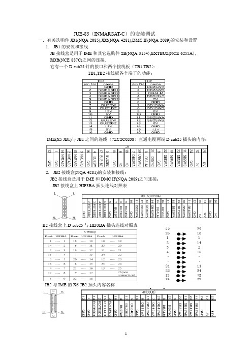
JUE-85(INMARSAT-C)的安装调试一.有关选购件JB1(NQA-2085),JB2(NQA-4281),DMC IF(NQA-2089)的安装和设置1.JB1的安装和接线:JB接线盒是用于IME和其它选购件SB(NQA-3154),EXTBUZ(NCE-6255A),RDB(NCE-887C)之间的连接,它有一个D-sub25针的接口和两个接线板(TB1,TB2):TB1,TB2接线板各个端子的功能:IME(X5 JB1)与JB1之间的连线(7ZCSC0208)直通电缆两端D-sub25插头的内容:2.JB2接线盒(NQA-4281)的安装和接线:JB2接线盒是用于IME和DMC IF(NQA-2089)之间连接:JB2接线盒上HIF3BA插头连线对照表B2接线盒上D-sub25与HIF3BA插头连线对照表JB2与IME的X6-JB2插头内容名称3.JB2 (NQA-4281)与DMC IF (NQA-2089)之间的连接关系3. 根据SB 按钮和RDB 盒的配置, IME(CU)PCB 上进行对应设置: 1).根据SB 按钮的配置,设定IME 部件内部CU 板(CMC-1257)的S1开关.打开IME 的上面顶盖,在CMC-1257板上设置S1开关,见下图:(工厂推荐设定) (SB1/SB2 ON) (SB1/SB2/SB3 ON) (SB1/SB2/SB3/SB4 ON) 2).根据RDB 盒的配置,设定IME 主机内部CU 板(CMC-1257)的S1的开关 打开IME 的上面顶盖,在CMC-1257板上设置S1开关DB1 ON(工厂推荐) DB1/RDB2 ON DB1/RDB2/RDB3 ON DB1/RDB2/RDB3/ RDB4IME (CU)PCB 板上S1 Dip 开关的设置主机的背后插座示意图:二.系统设置按照系统图连接各个部件 1.安装WinIST.exe 软件:PC 机;D-sub 9针电缆;软件WinIST.exe.将PC 机的COM 端口与JUE-85主机的<X3 MAIN DTE>的端口用D-sub 9针电缆连接,建立一个新的文件夹,并复制WinIST.exe 软件到这文件夹内,见下图:2.设置软件的启动和设置:双点击WinIST.exe,在屏幕窗口显示下面的报警字样时,点击〔OK 〕:在首次启动时的报警窗口 串行端口的报警窗口 选择与计算机连接的串行端口的号码,当显示下面窗口时,点击[OK]。
船舶地面站操作手册驾驶室仪器操作规程

INMARSAT-C船舶地面站操作规程
INMARSAT船舶地面站操作规程
中/高频/SSB无线电装置操作规程
甚高频无线电装置操作规程
高频无线电装置操作规程
NVATEX航行警告接收机操作规程
气象传真机操作规程
AIS船用全球自动识别系统操作规程
回声测深仪操作规程
GPS接收机操作规程
自动操舵仪操作规程
电罗经操作规程
磁罗经操作规程
电磁记程仪操作规程
VDR船载航行数据记录仪操作规程
操作规程
注意事项备注
双向无线电话操作规程
SART 操作规程
EPIRB 操作规程
INMARSAT-F 操作规程
RADAR 雷达操作规程
RADAR雷达操作规程
雷达操作规程
舵机操作程序
1、通知机舱舵机供电。
2、打开舵机开关,选择舵机组。
3、选择操纵方式,随动方式。
4、转动舵轮试验舵角指示。
5、最后舵角指示回零。
6、舵机备好。
应急舵操作规程。
- 1、下载文档前请自行甄别文档内容的完整性,平台不提供额外的编辑、内容补充、找答案等附加服务。
- 2、"仅部分预览"的文档,不可在线预览部分如存在完整性等问题,可反馈申请退款(可完整预览的文档不适用该条件!)。
- 3、如文档侵犯您的权益,请联系客服反馈,我们会尽快为您处理(人工客服工作时间:9:00-18:30)。
RADOME
Compass safe distance Standard compass: 0.1m Steering compass : 0.1m
INMARSAT-C EME
MODEL NAF-741GM SERIAL NO.
MADE IN JAPAN
<Type2>
WA R N I N G
Do not turn on the terminal under the primary power except the specific voltage (mentioned below).The primary power except the specific voltage may cause fire, electrical shock or malfunction. DC+24V(+19.2 V to +31.2 V) (When standard PSU, NBD-843A is used)
• Your communication data are transmitted via Inmarsat system and other global communications system, so unusually some errors may occur in communication theory same as the landlines. You are recommended to backup for your important data.
INMARSAT-C
MODEL JUE-85 SERIAL NO. DATE
IME
MODEL MASS
NTF-781GM 1.3kg
MADE IN JAPAN R 001VZAA1011
危険 D A N G E R
このカバーをはずすな 感電の恐れあり HIGH VOLTAGE DO NOT REMOVE THE COVER
This symbol denotes that improper handling poses a risk of causing injury or damage to the product and/or assets.
Example of symbols
The △ symbol denotes DANGER, WARNING or CAUTION. The inside illustration of the △symbol denotes meaning of the DANGER, WARNING or CAUTION more concretely. (This example warns of possible electrical shock.)
JUE-85
INMARSAT-C MOBILE EARTH STATION
INSTALLATION MANUAL
CODE NO. 7ZPSC0191
PREFACE
Thank you for purchase of the JRC Inmarsat-C, Mobile Earth Station, JUE-85. *Please read this Installation manual carefully and carry out proper installation. *Please keep the manual importantly to refer when it is necessary. *Please use it when questions and troubles are caused in installation, by any chance.
• Specifications of JUE-85 and its accessories may change without notice for improvement.
ii
BEFORE INSbols
This manual and the terminal are indicated the following safety symbols for your correct operation to prevent your and somebody’s injury or damage to the product and assets. The symbols and descriptions are as follows. You should understand well them before reading this manual and operating the terminal.
DANGER
Do not touch any internal parts with your hands or tools to avoid danger of electronic shock.
The lithium battery is built into JUE-85 (EME). Do not short-circuited of the terminal, do not give the high impact, and wet it to water. Those actions are dangerous against explosion.
• There is possibility that some functions of the terminal may not operate correctly depend on the hardware and software version of equipment connected to the terminal. Please confirm your equipment version before contact with the dealer or agent you purchased or JRC branches.
Do not approach the JUE-85(EME) while transmitting, It transmits microwave and strong microwave might be cause injury.
If a foreign substances, such as metal fragment, water, liquid and etc., are get into your JUE-85, turn off the power and contact with the agent you purchased or JRC branches. Continuous operation may cause fire, electrical shock or malfunction.
Technological, standard agreement proof and attestation number issued by Telecom Engineering Center Foundation in Japan.
iv
CAUTIONS DURING INSTALLATION
DANGER WARNING CAUTION
This symbol denotes that improper handling poses a high risk of causing death or serious injury.
This symbol denotes that improper handling poses a risk of causing death or serious injury.
IMPORTANT
Compass safe distance Standard compass: 0.2m Steering compass : 0.1m
Notes
R 001VZAA1011
Attestation number which means safe, high-quality product and suits EU instruction (Free circulation was permitted in the EU signatory).
The symbol denotes prohibited action. The inside illustration of the symbol denotes the specific prohibited action more concretely. (This example indicated disassembly is prohibited.)
CAUTIONS DURING INSTALLATION
WARNING
Do not bring JUE-85(EME) close to the fire, or put it in the fire. It causes the explosion, generation of heat, and the ignition of a built-in lithium battery.
The ● symbol denotes obligatory operation or instruction. The inside illustration of the ● symbol denotes obligatory operation or instruction more concretely. (This example indicates unplugging is the obligatory instruction.)
i
ATTENTIONS BEFORE USING
• JRC cannot accept responsibility for any loss due to incorrect operation, malfunction and other causes except product guarantee condition and liability by law.