JANS2N2218中文资料
2N2221-2N2222中文资料
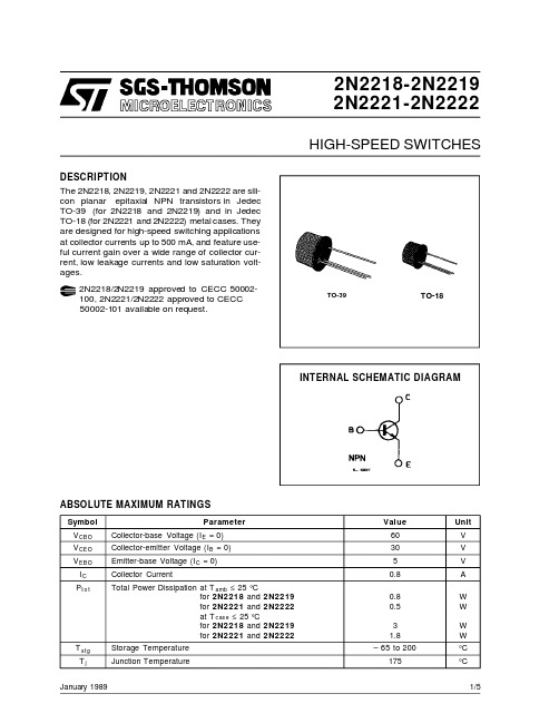
2N2218-2N22192N2221-2N2222January 1989HIGH-SPEED SWITCHESABSOLUTE MAXIMUM RATINGSSymbol ParameterValue Unit V CBO Collector-base Voltage (I E =0)60V V CEO Collector-emitter Voltage (I B =0)30V V EBO Emitter-base Voltage (I C =0)5V I C Collector Current0.8A P t o tTotal Power Dissipation at T amb ≤25°Cfor 2N2218and 2N2219for 2N2221and 2N2222at T c as e ≤25°C for 2N2218and 2N2219for 2N2221and 2N22220.80.531.8W W W W T st g Storage Temperature –65to 200°C T jJunction Temperature175°C DESCRIPTIONTO-18TO-39INTERNAL SCHEMATIC DIAGRAM2N2218/2N2219approved to CECC 50002-100,2N2221/2N2222approved to CECC 50002-101available on request.The 2N2218,2N2219,2N2221and 2N2222are sili-con planar epitaxial NPN transistors in Jedec TO-39(for 2N2218and 2N2219)and in Jedec TO-18(for 2N2221and 2N2222)metal cases.They are designed for high-speed switching applications at collector currents up to 500mA,and feature use-ful current gain over a wide range of collector cur-rent,low leakage currents and low saturation volt-ages.1/5ELECTRICAL CHARACTERISTICS (T amb =25°C unless otherwise specified)Symbol ParameterTest Conditions Min.Typ.Max.Unit I CBO Collector Cutoff Current (I E =0)V CB =50V V CB =50V T am b =150°C1010nA µA I E BO Emitter Cutoff Current (I C =0)V E B =3V 10nA V (BR)CBOColllector-base Breakdown Voltage (I E =0)I C =10µA 60V V (BR)CE O *Collector-emitter Breakdown Voltage (I B =0)I C =10mA 30V V (BR)EBOEmittter-base Breakdown Voltage (I C =0)I E =10µA 5VV CE (s at )*Collector-emitter Saturation VoltageI C =150mA I C =500mA I B =15mA I B =50mA 0.41.6V V V B E(s at )*Base-emitter Saturation VoltageI C =150mA I C =500mAI B =15mA I B =50mA 1.32.6V Vh F E *DC Current Gainfor 2N2218I C =0.1mA I C =1mA I C =10mA I C =150mA I C =500mA I C =150mA for 2N2219I C =0.1mA I C =1mA I C =10mA I C =150mA I C =500mA I C =150mA and 2N2221V CE =10V V CE =10V V CE =10V V CE =10V V CE =10V V CE =1V and 2N2222V CE =10V V CE =10V V CE =10V V CE =10V V CE =10V V CE =1V 2025354020203550751003050120300f T Transition Frequency I C =20mA f =100MHz V CE =20V 250MHz C CBO Collector-base Capacitance I E =0f =100kHz V CB =10V 8pF R e (h ie )Real Part of Input ImpedanceI C =20mA f =300MHzV CE =20V60Ω*Pulsed :pulse duration =300µs,duty cycle =1%.THERMAL DATA2N22182N22192N22212N2222R t h j-cas e R t h j-ambThermal Resistance Junction-case Thermal Resistance Junction-ambientMax Max50°C/W 187.5°C/W83.3°C/W 300°C/W2N2218-2N2219-2N2221-2N22222/5DIM.mminch MIN.TYP.MAX.MIN.TYP.MAX.A 12.70.500B 0.490.019D 5.30.208E 4.90.193F 5.80.228G 2.540.100H 1.20.047I 1.160.045L45o 45oLGI DAFE BHCTO-18MECHANICAL DATA00160432N2218-2N2219-2N2221-2N22223/5DIM.mminch MIN.TYP.MAX.MIN.TYP.MAX.A 12.70.500B 0.490.019D 6.60.260E 8.50.334F 9.40.370G 5.080.200H 1.20.047I 0.90.035L45o (typ.)LGI DAFE BHTO39MECHANICAL DATAP008B2N2218-2N2219-2N2221-2N22224/52N2218-2N2219-2N2221-2N2222 Information furnished is believed to be accurate and reliable.However,SGS-THOMSON Microelectronics assumes no responsability for the consequences of use of such information nor for any infringement of patents or other rights of third parties which may results from its use.No license is granted by implication or otherwise under any patent or patent rights of SGS-THOMSON Microelectronics.Specificationsmentioned in this publication are subject to change without notice.This publication supersedes and replaces all information previously supplied.SGS-THOMSON Microelectronics products are not authorized for use as critical components in life support devices or systems without express written approval of SGS-THOMSON Microelectonics.©1994SGS-THOMSON Microelectronics-All Rights ReservedSGS-THOMSON Microelectronics GROUP OF COMPANIESAustralia-Brazil-France-Germany-Hong Kong-Italy-Japan-Korea-Malaysia-Malta-Morocco-The Netherlands-Singapore-Spain-Sweden-Switzerland-Taiwan-Thailand-United Kingdom-U.S.A5/5。
2N2222AUB;中文规格书,Datasheet资料

Fea t ure•Ceramic surface mount package •Miniature package to minimize circuitboard area•Hermetically sealed•Qualification per MIL-S-19500/255•Same footprint and pin-out as many SOT-23 package transistorsDe s crip t ionThe JANTX/TXV2N2222AUB is a miniature hermetically sealed ceramic surface mount general purpose switching transistor. The miniature three pin ceramic package is ideal for upgrading commercial grade circuits to military reliability levels where plastic SOT-23devices have been used. The “UB” suffix denotes the 3 terminal chip carrier package, type “B” per MIL-PRF-19500/255.Typical screening and lot acceptance tests are provided on page 13-4. The burn-in condition is V CB = 30 V, P D = 200 mW, T A = 25o C, t =80 hrs. Refer to MIL-PRF-19500/255 for completerequirements. In addition, the TX and TXV versions are 100% thermal response tested.When ordering parts without processing,do not use a JAN prefix.Ab s o l ute Maxi m um Rat i ngs (T A = 25o C un l ess oth e r w ise noted)Collector- B ase Volt a ge ............................................. 75 V Collector- E mitter Volt a ge............................................ 50 V Emitter- B ase Volt a ge ............................................... 6.0 Col l ec t or Current- C ontinuous...................................... 800 mA Op e r a t i ng Junc t ion Tem p era t ure (T J )........................ -65o C to +200o C Stor a ge Junc t ion Tem p era t ure (T stg )........................ -65o C to +200o C Power Dis s i p a t ion @ T A = 25o C..................................... 0.3 W Power Dis s i p a t ion @ T C = 25o C .................................. 1.16 W (1)Sol d er i ng Tem p era t ure (va p or phase re f low for 30 sec.)................. 215o C Sol d er i ng Tem p era t ure (heated collet for 5 sec.)...................... 260o CNotes:(1) Der a te line a rly 6.6 mW/o C above 25o C.Prod u ct Bul l e t in JANTX, JANTXV, 2N2222AUB Sep t em b er 1996Surface Mount NPN General Purpose TransistorType JANTX, JANTXV, 2N2222AUBOp t ek Tech n ol o gy, Inc. 1215 W. Crosby Road Car r oll t on, Texas 75006 (972) 323- 2200 Fax (972) 323- 2396Types JANTX, JANTXV-2N2222AUBElec t ri c al Char a c t er i s t ics (T A = 25o C un l ess oth e r w ise noted)SYM B OL PA R AME T ER MIN MAX UNITS TEST CON D I T IONOff Char a c t er i s t icsV(BR)CBO Collector-Base Breakdown Voltage75V IC = 10 µA, I E = 0V(BR)CEO Collector-Emitter Breakdown Voltage50V I C = 10 mA, I B = 0V(BR)EBO Emitter-Base Breakdown Voltage 6.0V I E = 10 µA, I C = 0I CBO Collector-Base Cutoff Current10nA V CB = 60 V, I E = 010µA V CB = 60 V, I E = 0, T A = 150o CI EBO Emitter-Base Cutoff Current10nA V EB = 4 V, I C = 0I CES Collector-Emitter Cutoff Current50nA V CE = 50 VOn Char a c t er i s t icsh FE Forward-Current Transfer Ratio50-V CE = 10 V, I C = 0.1 mA75325-V CE = 10 V, I C = 1.0 mA100-V CE = 10 V, I C = 10 mA100300-V CE = 10 V, I C = 150 mA(2)30-V CE = 10 V, I C = 500 mA(2)35-V CE = 10 V, I C = 10 mA, T A = -55o C V CE(SAT)Collector-Emitter Saturation Voltage0.30V I C = 150 mA, I B = 15 mA(2)1.0V I C = 500 mA, I B = 15 mA(2)V BE(SAT)Base-Emitter Saturation Voltage0.60 1.20V I C = 150 mA, I B = 15 mA(2)2.0V I C = 500 mA, I B = 15 mA(2)Small-S ignal Char a c t er i s t icsh fe Small Signal Forward Current Transfer50-V CE = 10 V, I C = 1.0 mA, f = 1.0 kHz Ratio2.5-V CE = 20 V, I C = 20 mA, f = 100 MHzIh fe I Small Signal Forward Current TransferRatioC obo Open Circuit Output Capacitance8.0pF V CB = 10 V, 100 kHz ≤ f ≤ 1.0 MHzC ibo Input Capacitance (Output Open)25pF V EB = 0.5 V, 100 kHz ≤ f ≤ 1.0 MHzSwitch i ng Char a c t er i s t icst on Turn-On Time35ns V CC = 30 V, I C = 150 mA, I B1 = 15 mAt off Turn-Off Time300ns V CC = 30 V, I C = 150 mA, I B1 = I B2 = 15 mA (2) Pulse Width ≤ 300 µs, Duty Cycle ≤ 2.0%Op t ek Tech n ol o gy, Inc. 1215 W. Crosby Road Car r oll t on, Texas 75006 (972) 323- 2200 Fax (972) 323- 2396分销商库存信息: OPTEK-TECHNOLOGY 2N2222AUB。
JANSR2N7382中文资料
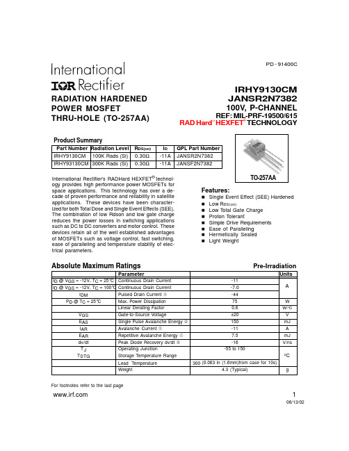
TO-257AA
Features:
n Single Event Effect (SEE) Hardened n Low RDS(on) n Low Total Gate Charge n Proton Tolerant n Simple Drive Requirements n Ease of Paralleling n Hermetically Sealed n Light Weight
300 (0.063 in (1.6mm)from case for 10s)
4.3 (Typical)
g
For footnotes refer to the last page
1
06/13/02
元器件交易网
IRHY9130CM, JANSR2N7382
— 70
6.8 —
nH Measured from drain lead (6mm/0.25in. from
package) to source lead (6mm/0.25in. from
package)
Ciss Coss Crss
Input Capacitance Output Capacitance Reverse Transfer Capacitance
Pre-Irradiation
Electrical Characteristics @ Tj = 25°C (Unless Otherwise Specified)
Parameter
Min
BVDSS
Drain-to-Source Breakdown Voltage -100
∆BVDSS/∆TJ Temperature Coefficient of Breakdown — Voltage
2N2218A中文资料

• Meets MIL 19500 /251• Collector - Base Voltage 75V • Collector - Current 800 mA• Medium Current, Bipolar TransistorMaximum RatingsRATINGSYMBOL VALUE UNIT Collector - Emitter Voltage V CEO 50Vdc Collector - Base Voltage V CBO 75Vdc Emitter - Base VoltageV EBO6Vdc Collector Current - ContinuousI C800mAdc Total Device Dissipation @ T A = 25 °C P D 0.8WATTS Derate above 25 °C4.6mW/°C Total Device Dissipation @ T C = 25 °C P D 3.0WATTS Derate above 25 °C17.0mW/°C Operating Junction&Storage Temperature RangeT J , T stg- 55 to +200°CThermal CharacteristicsCHARACTERISTICSYMBOL MAX UNIT Thermal Resistance, Junction to Ambient R θ JA 217°C/W Thermal Resistance, Junction to CaseR θ JC59°C/WSWITCHING TRANSISTOR JAN, JANTX, JANTXVElectrical Characteristics (T A = 25°C unless otherwise noted)OFF CHARACTERISTIC SYMBOL MIN MAX UNIT Collector - Emitter Breakdown Voltage (1)V(BR)CEO( I C = 10 mA dc, I B = 0 )50Vdc Collector - Base Breakdown Voltage V(BR)CBO( I C = 10 µAdc, I E = 0 )75Vdc Emitter - Base Breakdown Voltage V(BR)EBO( I E = 10 µAdc, I C = 0 ) 6Vdc Collector - Emitter Cutoff Current I CES( V CE = 50 Vdc )10nAdc Collector - Base Cutoff Current I CBO( V CB = 60 Vdc, I E = 0 )10nAdc ( V CB = 60 Vdc, I E = 0, T A = 150 °C )10µAdc Emitter - Base Cutoff Current I EBO( V EB = 4 Vdc )10nAdc ( V EB = 6 Vdc )10µAdc ON CHARACTERISTIC SYMBOL MIN MAX UNIT DC Current Gain h FE( I C = 0.1 mA dc, V CE = 10 Vdc ) (1)30( I C = 1 mA dc, V CE = 10 Vdc ) (1)35150( I C = 10 mA dc, V CE = 10 Vdc ) (1)40( I C = 150 mA dc, V CE = 10 Vdc ) (1)40120( I C = 500 mA dc, V CE = 10 Vdc ) (1)20( I C = 10 mA dc, V CE = 10 Vdc, T J =-55°C) (1)35Collector - Emitter Saturation Voltage V CE(sat)( I C = 150 mAdc, I B = 15 mAdc ) (1)0.3Vdc ( I C = 500 mAdc, I B = 50 mAdc ) (1) 1.0Vdc Base - Emitter Saturation Voltage V BE(sat)( I C = 150 mAdc, I B = 15 mAdc ) (1)0.6 1.2Vdc ( I C = 500 mAdc, I B = 50 mAdc ) (1) 2.0Vdc 1. Pulse Test: Pulse Width ≤ 300 µs, Duty Cycle ≤.2%Electrical Characteristics (T A = 25°C unless otherwise noted)SMALL - SIGNAL CHARACTERISTICS SYMBOL MIN MAX UNIT Output Capacitance C obo( V CB = 10 Vdc, I E = 0, 100kHz ≤ f ≤ 1 MHz )8.0pF Input Capacitance C ibo( V EB = 0.5 Vdc, I C = 0, 100kHz ≤ f ≤ 1 MHz )25pF SWITCHING CHARACTERISTICS SYMBOL MIN MAX UNIT Turn - On Time t on( V CC = 30 Vdc, I C = 150 mAdc,I B1 =15 mAdc) ( See FIGURE 1 )35ns Turn - Off Time t off( V CC = 30 Vdc, I C = 150 mAdc,I B1 = - I B2 = 15 mAdc) ( See FIGURE 2 )300ns Small - Signal AC Characteristics (T A = 25°C)LOW FREQUENCY SYMBOL MIN MAX UNIT Common - Emitter Forward Current Transfer Ratio h fe( I C = 1 mA, V CE = 10 V, f = 1kHz )35HIGH FREQUENCYCommon - Emitter Forward Current Transfer Ratio|h fe|( I C = 20 mA, V CE = 20 V, f = 100 MHz ) 2.512S p i c e M o d e l (based upon typical device characteristics) *1Q2N2218A NPN ( IS = 21.2f XTI = 3.0 EG = 1.11 VAF= 103.8 BF = 90.7 ISE = 3.34p + NE = 2.05 IKF = 1.255 NK = 0.9394 XTB = 1.5 BR = 1.031 ISC = 3.299p + NC = 1.605 IKR =0.8992 RC = 0.0 CJC = 19.4p MJC = 0.3333 VJC = 0.75 + FC = 0.5 CJE=29.6p MJE= 0.3333 VJE = 0.75 TR = 275.0n TF=564.5p + ITF = 1.0 XTF= 0.0 VTF=10.0 )*1. Microsemi Corp. claims no responsibility for misapplication of Spice Model information. Spice modeling should be used as a precursor guide to in-circuit performance. Actual performance is the responsibility of the user/designer.TO-39 CASE OUTLINEDIE OUTLINEFIGURE 1 Saturated Turn-on Time Test CircuitFIGURE 2 Saturated Turn-off Time Test CircuitFIGURE 3FIGURE 4.0001.001.01.11IC COLLECTOR CURRENT (A)255075100125h F E C U R R E N T G A I N255075100125DC CURRENT GAINVCE = 10 Vtyp @ 25Ctyp @ -55C.0001.001.01.11IB, BASE CURRENT (A)0.00.20.40.60.81.0V C E , C O L L E C T O R -E M I T T E R (V )0.00.20.40.60.81.0COLLECTOR SATURATION vs BASE CURRENTTJ = 25 CIC = 500 mAIC = 150 mAFIGURE 5FIGURE 6.001.01.11IB, BASE CURRENT (A)0.500.751.001.25V B E , B A S E -E M I T T E R V O L T A G E (V )0.500.751.001.25BASE SATURATION vs BASE CURRENTTJ = 25 CIC = 150 maIC = 500 ma.01.1110100REVERSE JUNCTION VOLTAGE (V)51015202530J U N C T I O N C A P A C I T A N C E (p F )051015202530JUNCTION CAPACITANCE TJ = 25 C 100 kHz < f < 1 MHzCOBOCIBOFIGURE 7FIGURE 8101001000COLLECTOR CURRENT (mA)10100t o n T I M E (n s )10100SWITCHING TURN - 0N TIMETJ = 25 C IC/IB = 10min.max.50010100COLLECTOR CURRENT (mA)1001000t o f f T I M E (n s )1001000SWITCHING TURN - OFF TIMETJ = 25 C IC/IB = 10min.max.FIGURE 91101001000FREQUENCY MHz.01.11N O R M A L I Z E D G A I N.01.11NORMALIZED GAIN VS FREQUENCY TJ = 25C IC = 20 mA VCE = 20 V。
2N2222中文资料_数据手册_参数

Product specification
2N2222; 2N2222A
SYMBOL
PARAMETER
CONDITIONS
MIN. MAX. UNIT
Switching times (between 10% and 90% levels); see Fig.2
DISCRETE SEMICONDUCTORS
DATA SHEET
M3D125
2N2222; 2N2222A NPN switching transistors
Product specification Supersedes data of September 1994 File under Discrete Semiconductors, SC04
DC current gain 2N2222A
IE = 0; VCB = 60 V IE = 0; VCB = 60 V; Tamb = 150 °C IC = 0; VEB = 3 V IC = 0.1 mA; VCE = 10 V IC = 1 mA; VCE = 10 V IC = 10 mA; VCE = 10 V IC = 150 mA; VCE = 1 V; note 1 IC = 150 mA; VCE = 10 V; note 1 IC = 10 mA; VCE = 10 V; Tamb = −55 °C
SYMBOL
PARAMETER
Rth j-a Rth j-c
thermal resistance from junction to ambient thermal resistance from junction to case
CONDITIONS in free air
JAN2N3821中文资料
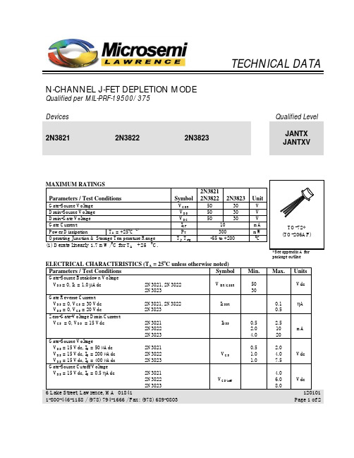
TECHNICAL DATA N-CHANNEL J-FET DEPLETION MODEQualified per MIL-PRF-19500/375Devices Qualified Level2N3821 2N3822 2N3823JANTX JANTXVMAXIMUM RATINGSParameters / Test Conditions Symbol 2N38212N3822 2N3823 UnitGate-Source Voltage V GSR50 30 V Drain-Source Voltage V DS50 30 V Drain-Gate Voltage V DG50 30 V Gate Current I GF 10 mA Power Dissipation T A = +250C (1)P T300 mW Operating Junction & Storage Temperature Range T j, T stg-55 to +200 0C(1) Derate linearly 1.7 mW/C for T A +25 C.package outline ELECTRICAL CHARACTERISTICS (T A = 250C unless otherwise noted)Parameters / Test Conditions Symbol Min. Max. Units Gate-Source Breakdown VoltageV DS = 0, I G = 1.0 µAdc 2N3821, 2N3822 2N3823 V(BR)GSSR5030VdcGate Reverse CurrentV DS = 0, V GS = 30 Vdc 2N3821, 2N3822 V DS = 0, V GS = 20 Vdc 2N3823 I GSSR0.10.5ηAZero-Gate-Voltage Drain CurrentV GS = 0, V DS = 15 Vdc 2N3821 2N3822 2N3823 I DSS0.52.04.02.51020mAGate-Source VoltageV DS = 15 Vdc, I D = 50 µAdc 2N3821V DS = 15 Vdc, I D = 200 µAdc 2N3822 V DS = 15 Vdc, I D = 400 µAdc 2N3823 V GS0.51.01.02.04.07.5VdcGate-Source Cutoff VoltageV DS = 15 Vdc, I D = 0.5 ηAdc 2N38212N3822 2N3823 V GS(off)4.06.08.0Vdc6 Lake Street, Lawrence, MA 018411-800-446-1158 / (978) 794-1666 / Fax: (978) 689-0803120101 Page 1 of 22N3821, 2N3822, 2N3823 JAN SERIESParameters / Test Conditions Symbol Min. Max. Units Small-Signal Common Source, Short-Circuit Forward Transfer AdmittanceV GS = 0, V DS = 15 Vdc, f = 1.0 kHz 2N38212N3822 2N3823 |y fs|1150030003500450065006500µSSmall-Signal Common Source, Short-Circuit Output AdmittanceV GS = 0, V DS = 15 Vdc, f = 1.0 kHz 2N38212N3822 2N3823 |y os|102035µSSmall-Signal, Common-Source Short-Circuit Input CapacitanceV GS = 0, V DS = 15 Vdc, 100 kHz ≤ f ≤ 1.0 MHz C iss 6.0 pF Small-Signal, Common-Source Reverse Transfer CapacitanceV DS = 15 Vdc, V GS = 0, 100 kHz ≤ f ≤ 1.0 MHz2N3821, 2N3822 2N3823C rss3.02.0pFSmall-Signal Common Source, Short-Circuit Forward Transfer AdmittanceV GS = 0, V DS = 15 Vdc, f = 100 MHz 2N3821f = 100 MHz 2N3822 f = 200 MHz 2N3823 |y fs|2150030003200µSSmall-Signal, Common-Source Short-Circuit Input ConductanceV GS = 0, V DS = 15 Vdc, f = 200 MHz 2N3823 (only)g is 800 µS Small-Signal, Common-Source Short-Circuit Output ConductanceV GS = 0, V DS = 15 Vdc, f = 200 MHz 2N3823 (only)g os 200 µS Common Source Spot Noise FigureV GS = 0, V DS = 15 Vdc, R G = 1MΩf = 10 Hz2N3821, 2N3822f = 1.0 kHz 2N3821, 2N3822, 2N3823NF1 5.02.0dBCommon Source Spot Noise FigureV GS = 0, V DS = 15 Vdc, R G = 1kΩf = 105 MHz2N3823 (only)NF22.5dB6 Lake Street, Lawrence, MA 018411-800-446-1158 / (978) 794-1666 / Fax: (978) 689-0803120101 Page 2 of 2。
JANSR2N7425中文资料
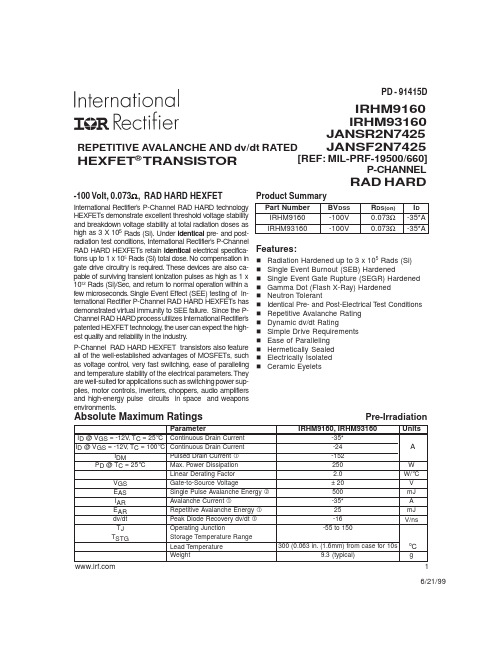
Pre- @ VGS = -12V, TC = 25°C Continuous Drain Current
ID @ VGS = -12V, TC = 100°C Continuous Drain Current
IDM
Pulsed Drain Current
* Current is limited by pin diameter. 2
Thermal Resistance
Parameter
RthJC RthCS RthJA
Junction-to-Case Case-to-Sink Junction-to-Ambient
Min Typ Max
— — 0.50 — 0.21 — — — 48
Units °C/W
Test Conditions Typical socket mount
Modified MOSFET symbol showing the internal inductances.
Ciss Coss Crss
Input Capacitance Output Capacitance Reverse Transfer Capacitance
— 6000 — — 1400 — pF — 400 —
Absolute Maximum Ratings
Product Summary
Part Number
BVDSS
IRHM9160
-100V
IRHM93160
-100V
RDS(on) 0.073Ω 0.073Ω
ID -35*A -35*A
Features:
n Radiation Hardened up to 3 x 10⁵ Rads (Si) n Single Event Burnout (SEB) Hardened n Single Event Gate Rupture (SEGR) Hardened n Gamma Dot (Flash X-Ray) Hardened n Neutron Tolerant n Identical Pre- and Post-Electrical Test Conditions n Repetitive Avalanche Rating n Dynamic dv/dt Rating n Simple Drive Requirements n Ease of Paralleling n Hermetically Sealed n Electrically Isolated n Ceramic Eyelets
2N2222A中文资料
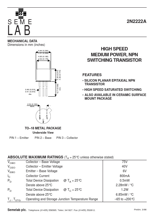
Semelab plc.
Telephone (01455) 556565. Telex: 341927. Fax (01455) 552612.
12.7 (0.500) min.
元器件交易网
LAB
ELECTRICAL CHARACTERISTICS (TA = 25°C unless otherwise stated)
Min.
40 75 6
Typ.
Max. Unit
V
V V 10 0.01 10 10 20 0.3 1 nA µA nA nA
V V
0.6 35 50 75 35 100 50 40 300
1.2 2
— 300
f = 100MHz f = 100kHz f = 100kHz f = 1kHz f = 1kHz
5.33 (0.210) 4.32 (0.170)
FEATURES
• SILICON PLANAR EPITAXIAL NPN TRANSISTOR • HIGH SPEED SATURATED SWITCHING • ALSO AVAILABLE IN CERAMIC SURFACE MOUNT PACKAGE
0.48 (0.019) 0.41 (0.016) dia.
2.54 (0.100) Nom.
3 2
1
TO–18 METAL PACKAGE
Underside View PIN 1 – Emitter PIN 2 – Base PIN 3 – Collector
ABSOLUTE MAXIMUM RATINGS (TA = 25°C unless otherwise stated)
Stabilization mechanisms of soil organic matter- Implications for C-saturation of soils
Plant and Soil241:155–176,2002.©2002Kluwer Academic Publishers.Printed in the Netherlands.155 ReviewStabilization mechanisms of soil organic matter:Implications forC-saturation of soilsJ.Six1,R.T.Conant,E.A.Paul&K.PaustianNatural Resource Ecology Laboratory,Colorado State University,Fort Collins,CO80523,U.S.A.1Corresponding author∗Received3January2001.Accepted in revised form13February2002AbstractThe relationship between soil structure and the ability of soil to stabilize soil organic matter(SOM)is a key element in soil C dynamics that has either been overlooked or treated in a cursory fashion when developing SOM models. The purpose of this paper is to review current knowledge of SOM dynamics within the framework of a newly proposed soil C saturation concept.Initially,we distinguish SOM that is protected against decomposition by various mechanisms from that which is not protected from decomposition.Methods of quantification and characteristics of three SOM pools defined as protected are discussed.Soil organic matter can be:(1)physically stabilized,or protected from decomposition,through microaggregation,or(2)intimate association with silt and clay particles, and(3)can be biochemically stabilized through the formation of recalcitrant SOM compounds.In addition to behavior of each SOM pool,we discuss implications of changes in land management on processes by which SOM compounds undergo protection and release.The characteristics and responses to changes in land use or land management are described for the light fraction(LF)and particulate organic matter(POM).We defined the LF and POM not occluded within microaggregates(53–250µm sized aggregates as unprotected.Our conclusions are illustrated in a new conceptual SOM model that differs from most SOM models in that the model state variables are measurable SOM pools.We suggest that physicochemical characteristics inherent to soils define the maximum protective capacity of these pools,which limits increases in SOM(i.e.C sequestration)with increased organic residue inputs.IntroductionMost current models of SOM dynamics assumefirst-order kinetics for the decomposition of various con-ceptual pools of organic matter(McGill,1996;Paus-tian,1994),which means that equilibrium C stocks are linearly proportional to C inputs(Paustian et al., 1997).These models predict that soil C stocks can, in theory,be increased without limit,provided that C inputs increase without limit,i.e.there are no as-sumptions of soil C saturation.While these models have been largely successful in representing SOM dynamics under current conditions and management practices(e.g.Parton et al.,1987,1994;Paustian et ∗FAX No:+1-970-491-1965.E-mail:johan@ al.,1992;Powlson et al.,1996),usually for soils with low to moderate C levels(e.g.<5%),there is some question of their validity for projecting longer term SOM dynamics under scenarios of ever increasing C inputs(e.g.Donigian et al.,1997).Such scenarios are particularly relevant with the development of new technology designed to promote soil C sequestration through increasing plant C inputs.Native soil C levels reflect the balance of C inputs and C losses under native conditions(i.e.productivity, moisture and temperature regimes),but do not neces-sarily represent an upper limit in soil C stocks.Empir-ical evidence demonstrates that C levels in intensively managed agricultural and pastoral ecosystems can ex-ceed those under native conditions.Phosphorous fer-tilization of Australian pasture soils can increase soil C by150%or more relative to the native condition156(Barrow,1969;Ridley et al.,1990;Russell1960). Soil C levels under long-term grassland(‘near native’) vegetation have also been exceeded in high productiv-ity mid-western no-tillage(NT)systems(Ismail et al., 1994)as well as in sod plots with altered vegetation (Follett et al.,1997).Hence,native soil C levels may not be an appropriate measure of the ultimate C sink capacity of soils.There are several lines of evidence that suggest the existence of a C saturation level based on physiochem-ical processes that stabilize or protect organic com-pounds in soils.While many long-termfield experi-ments exhibit a proportional relationship between C inputs and soil C content across treatments(Larson et al.,1972;Paustian et al.,1997),some experiments in high C soils show little or no increase in soil C content with two to three fold increases in C inputs (Campbell et al.,1991;Paustian et al.,1997;Solberg et al.,1997).Various physical properties(e.g.silt plus clay content and microaggregation)of soil are thought to be involved in the protection of organic materials from decomposer organism.However,these proper-ties and their exerted protection seem to be limited by their characteristics(e.g.surface area),which is con-sistent with a saturation phenomenon(Hassink,1997; Kemper and Koch,1966).A number of soil organic matter models have been developed in the last30years.Most of these mod-els represent the heterogeneity of SOM by defining several pools,typically three tofive,which vary in their intrinsic decay rates and in the factors which control decomposition rates(see reviews by McGill, 1996;Parton,et al.,1994;Paustian,1994).Alternat-ive formulations,whereby specific decomposition rate varies as a function of a continuous SOM quality spec-trum(i.e.instead of discrete pools),have also been developed(e.g.Bosatta and Agren,1996).However, in either case,the representation of the model pools (or quality spectrum)is primarily conceptual in nature. While such models can be successfully validated us-ing measurements of total organic carbon and isotopic ratios of total C(e.g.Jenkinson and Rayner,1977), the individual pools are generally only loosely associ-ated with measurable quantities obtained with existing analytical methods.Consequently,it is not straight-forward to falsify or test the internal dynamics of C transfers between pools and changes in pool sizes of the current SOM models with conceptual pool defin-itions because a direct comparison to measured pool changes is not possible.A closer linkage between theoretical and measur-able pools of SOM can be made by explicitly defining model pools to coincide with measurable quantities or by devising more functional laboratory fractiona-tion procedures or both.The phrases‘modeling the measurable’and‘measuring the modelable’have been coined as representing the two approaches towards a closer reconciliation between theoretical and experi-mental work on SOM(Christensen,1996;Elliott et al.,1996).Various attempts have been made to correlate ana-lytical laboratory fractions with conceptual model pools,with limited success.Motavalli et al.(1994) compared laboratory measurements of C mineraliza-tion with simulations by the Century model(Parton et al.,1994)for several tropical soils.When the active and slow pools in the model were initialized using laboratory determinations of microbial+soluble C for the active pool and light fraction for the slow pool,C mineralization was consistently underestim-ated,although all fractions were highly significantly correlated to C mineralization in a regression ana-lysis.Magid et al.(1996)unsuccessfully attempted to trace14C labeled plant materials using three size-density fractionation methods to define an‘active’pool.Metherell(1992)found that the slow pool in Century was much larger than the particulate organic matter(POM)fraction isolated from a Haplustoll by Cambardella and Elliott(1992).However,Balesdent (1996)found that POM isolated after mild disrup-tion corresponds to the plant structural compartment (RPM)of the Rothamsted carbon model(Jenkinson and Rayner,1997).Acid hydrolysis has been used to estimate Century’s passive C pool(Paul et al.,1997a; Trumbore,1993),but it seems to slightly overestimate the size(Paul et al.,1997a;Trumbore,1993),though not the C turnover rate,of the passive pool(Trumbore, 1993).Nevertheless,Paul et al.(1999)used extended laboratory incubations in combination with acid hy-drolysis to define an active,slow and passive pool of C and were successful in modeling the evolution of CO2in thefield based on these pools.These studies suggest that attempting to measure the modelable has had minimal success to date.There have been a few recent attempts to more closely integrate models and measurements of physi-cochemically defined pools by‘modeling the measur-able’,although Elliott et al.(1996)and Christensen (1996)have presented conceptual models for this ap-proach.Arah(2000)proposed an approach based on analytically defined pools and measurements of13C157Figure1.The protective capacity of soil(which governs the silt-and clay protected C and microaggregate protected C pools),the biochemically stabilized C pool and the unprotected C pool define a maximum C content for soils.The pool size of each fraction is determined by their unique stabilizing mechanisms.and15N stable isotope tracers to derive parameters for a model with measurable pools.The approach con-siders all possible transformations between measured C and N pools and devises a system of equations using observed changes in total C and N and13C and15N for each fraction to solve all model unknowns.Necessary requirements of such an approach are that the analyt-ical fractions are distinct and together account for the total carbon inventory.The objective of this review paper is to summar-ize current knowledge on SOM dynamics and sta-bilization and to synthesize this information into a conceptual SOM model based on physicochemically defined SOM pools.This new model defines a soil C-saturation capacity,or a maximum soil C storage potential,determined by the physicochemical proper-ties of the soil.We propose that the conceptual model developed from this knowledge may form the basis for a simulation model with physicochemically measur-able SOM pools as state variables rather than with the biologically defined pools by Paul et al.(1999).Protected SOM:Stabilization mechanisms, characteristics,and dynamicsThree main mechanisms of SOM stabilization have been proposed:(1)chemical stabilization,(2)phys-ical protection and(3)biochemical stabilization (Christensen,1996;Stevenson,1994).Chemical sta-bilization of SOM is understood to be the result of the chemical or physicochemical binding between SOM and soil minerals(i.e.clay and silt particles).Indeed, many studies have reported a relationship between stabilization of organic C and N in soils and clay or silt plus clay content(Feller and Beare,1997; Hassink,1997;Ladd et al.,1985;Merckx et al., 1985;Sorensen,1972).In addition to the clay con-tent,clay type(i.e.2:1versus1:1versus allophanic clay minerals)influences the stabilization of organic C and N(Feller and Beare,1997;Ladd et al.1992; Sorensen,1972;Torn et al.,1997).Physical protection by aggregates is indicated by the positive influence of aggregation on the accumulation of SOM(e.g.Ed-wards and Bremner,1967;Elliott,1986;Jastrow, 1996;Tisdall and Oades,1982;Six et al.,2000a). Aggregates physically protect SOM by forming phys-ical barriers between microbes and enzymes and their substrates and controlling food web interactions and consequently microbial turnover(Elliott and Coleman, 1988).Biochemical stabilization is understood as the stabilization of SOM due to its own chemical com-position(e.g.recalcitrant compounds such as lignin and polyphenols)and through chemical complexing processes(e.g.condensation reactions)in soil.For our analyses,we divide the protected SOM pool into three pools according to the three stabilization mechanisms described(Figure1).The three SOM pools are the silt-and clay-protected SOM(silt and clay defined as <53µm organomineral complexes),microaggregate-protected SOM(microaggregates defined as53–250µm aggregates),and biochemically protected SOM. Chemical stabilization:Silt-and clay-protected SOM The protection of SOM by silt and clay particles is well established(Feller and Beare,1997;Hassink, 1997;Ladd et al.,1985;Sorensen,1972).Hassink (1997)examined the relationship between SOM frac-tions and soil texture and found a relationship between the silt-and clay-associated C and soil texture,though he did notfind any correlation between texture and amount of C in the sand-sized fraction(i.e.POM C).Based on thesefindings,he defined the capacity158Table1.Regression equations relating silt plus clay proportion to silt and clay associated CSize class a Ecosystem Intercept Slope r20–20µm Cultivated 4.38±0.68b0.26±0.010.41Grassland 2.21±1.940.42±0.080.44Forest−2.51±0.550.63±0.010.550–50µm Cultivated7.18±3.040.2±0.040.54Grassland16.33±4.690.32±0.070.35Forest16.24±6.010.24±0.080.35Size class Clay type Intercept Slope r20–20µm1:1 1.22±0.370.30±0.010.742:1 3.86±0.490.41±0.010.390–50µm1:1 5.5±5.930.26±0.130.382:114.76±2.370.21±0.030.07a Two size classes for silt and clay were reported in the literature.b Value±95%confidence interval.of soil to preserve C by its association with silt and clay particles.Studies investigating the retention of specific microbial products(i.e.amino sugars)cor-roborate the proposition of Hassink(1997)that C associated with primary organomineral complexes arechemically protected and the amount of protection in-creased with an increased silt plus clay proportion of the soil(Chantigny et al.,1997;Guggenberger et al., 1999;Puget et al.,1999;Sorensen,1972).Puget et al.(1999)reported an enrichment of microbial derived carbohydrates in the silt plus clay fraction compared to the sand fraction of no-tilled and conventional tilled soils.However,the amount stabilized by silt and clay differs among microbial products.For example,Gug-genberger et al.(1999)reported a higher increase of glucosamine than muramic acid under no-tillage at sites with a high silt plus clay content.A reexamin-ation of the data presented by Chantigny et al.(1997) leads to the observation that the glucosamine/muramic acid ratio was only higher in perennial systems com-pared to annual systems in a silty clay loam soil and not in a clay loam soil.The silty clay loam soil had a higher silt plus clay content.We expanded the analysis of Hassink(1997)of the physical protection capacity for C associated with primary organomineral complexes(Figure2)across ecosystems(i.e.forest,grassland,and cultivated sys-tems),clay types(i.e.1:1versus2:1),and size ranges for clay and silt(0–20µm and0–50µm;see Ap-Figure 2.The relationship between silt+clay content(%)and silt+clay associated C(g silt+clay C kg−1soil)for grassland,forest and cultivated ecosystems.A differentiation between1:1clay and 2:1clay dominated soils is also made.The relationships indicate a maximum of C associated with silt and clay(i.e.C saturation level for the clay and silt particles),which differs between forest and grassland ecosystems and between clay types.Two size boundaries for silt+clay were used(A)0–20µm and(B)0–50µm. pendices for details).Following the methodology of Hassink(1997)we performed regressions(Figure2 and Table1)between the C content associated with silt and clay particles(g C associated with silt and clay particles kg−1soil;Y axis)and the proportion of silt and clay particles(g silt plus clay g−1soil;X axis).All regressions were significant(P<0.05)and comparison of regression lines revealed that the influ-ence of soil texture on mineral-associated C content differed depending on the size range used for clay and silt particles.Consequently,we did regressions for two different size classes of silt and clay particles(i.e.0–20µm and0–50µm;Figure2and Table1).The intercept for the0–50µm silt and clay particles was significantly higher than for the0–20µm silt and clay particles(Table1).This difference in intercept was159probably a result of the presence of larger sized(20–50µm)silt-sized aggregates in the0–50µm than in the 0–20µm silt and clay particles.These larger silt-sized aggregates have more C per unit material because ad-ditional C binds the primary organomineral complexes into silt-sized aggregates(Tisdall and Oades,1982). However the difference in intercept might also be the result of POM particles of the size20–50µm as-sociated with the0–50µm fraction(Turchenek and Oades,1979).Intercepts for cultivated and forest eco-systems were significantly different for the0–50µm particles,but were only marginally significantly dif-ferent(P<0.06)for the0–20µm particles.Slopes for grassland soils(0–20µm particles)were signi-ficantly different than those for forest and cultivated soils.The differences between grasslands and cultiv-ated lands are likely due to differences in input and disturbance,which causes a release of SOM and con-sequently increased C availability for decomposition. An explanation for the significantly different slopes for grassland and forest soils(Table1)is not imme-diately apparent.Especially that the slope is higher for forest than grassland slopes.This is in contrast to the suggestion that grassland-derived soils have a higher potential of C stabilization than forest-derived because of their higher base saturation(Collins et al.,2000; Kononova,1966).Consequently,this difference in C stabilization by silt and clay particles between forest and grassland systems should be investigated further.In contrast to Hassink(1997),we found signific-antly different relationships for1:1clays versus2:1 clays regressions and for the cultivated versus grass-land regressions(Figure2and Table1)for the0–20µm particles.The effect of clay type was also signific-ant for the0–50µm particles.This lower stabilization of C in1:1clay dominated soils is probably mostly re-lated to the differences between the clay types(see be-low).However,the effect of climate can not be ignored in this comparison because most1:1clay dominated soils were located in(sub)tropical regions.The higher temperature and moisture regimes in(sub)tropical re-gions probably also induce a faster decomposition rate and therefore contributes to the lower stabilization of C by the1:1clays.Nevertheless we believe that the type of clay plays an important role because different types of clay(i.e.1:1and2:1clays)have substantial differences in CEC and specific surface(Greenland, 1965)and should,consequently,have different ca-pacities to adsorb organic materials.In addition,Fe-and Al-oxides are most often found in soils domin-ated by1:1minerals and are strongflocculants.By being strongflocculants,Fe-and Al-oxides can re-duce even further the available surface for adsorption of SOM.We are not certain why soils examined by Hassink(1997)did not follow this reduced capacity to adsorb organic materials;few soils dominated by 1:1clays,however,were included in the data set used by Hassink(1997)and most of them had a low car-bon content.Nevertheless,the difference between the two studies might also be a result of the contrast-ing effect the associated Fe-and Al-oxides can have. The strongflocculating oxides can reduce available surface(see above)but they might also co-flocculate SOM and consequently stabilize it.Therefore,it ap-pears that mechanisms with contrasting effects on SOM stabilization exist and the net effect still needs to be investigated.The different regression lines for grassland and cultivated systems are in accordance with Feller et al.(1997).They also found a signific-ant lower slope for the regression line between the amount of0–2µm particles and the C contained in the0–2µm fraction of cultivated soils compared to non-cultivated soils.The lack of influence of cultiv-ation on the silt and clay associated C observed by Hassink(1997)was probably a result of the low pro-portion of silt and clay and high SOM contents of the soils used.The silt-and clay-associated C formed a small fraction of the total C in his soils.Consequently, sand-associated C accounted for the majority of total soil C.Given this dominance of sand-associated C and its greater sensitivity to cultivation than silt-and clay-associated C(Cambardella and Elliott,1992),in which C is transferred from the sand associated fraction to the silt-and clay-associated fractions during decom-position(Guggenberger et al.,1994),a loss of silt-and clay-associated C upon cultivation is likely to be minimal.In summary,we found,as Hassink(1997)did,a direct relationship between silt plus clay content of soil and the amount of silt-and clay-protected soil C, indicating a saturation level for silt and clay associated C.This relationship was different between different types of land use,different clay types,and for differ-ent determinations of silt plus clay size class.Also, the silt-and clay-associated soil organic matter was reduced by cultivation.Physical protection:Microaggregate-protected SOM The physical protection exerted by macro-and/or mi-croaggregates on POM C is attributed to:(1)the compartmentalization of substrate and microbial bio-160mass(Killham et al.,1993;van Veen and Kuikman, 1990),(2)the reduced diffusion of oxygen into macro-and especially microaggregates(Sexstone et al.,1985) which leads to a reduced activity within the aggregates (Sollins et al.,1996),and(3)the compartmentalization of microbial biomass and microbial grazers(Elliott et al.,1980).The compartmentalization between sub-strate and microbes by macro-and microaggregates is indicated by the highest abundance of microbes on the outer part of the aggregates(Hattori,1988)and a substantial part of SOM being at the center of the aggregates(Elliott and Coleman,1988;Golchin et al., 1994).In addition,Bartlett and Doner(1988)repor-ted a higher loss of amino acids by respiration from the aggregate surfaces than from within aggregates. Priesack and Kisser-Priesack(1993)showed that the rate of glucose utilization decreased with distance into the aggregate.The inaccessibility of substrate for mi-crobes within aggregates is due to pore size exclusion and related to the water-filled porosity(Killham et al., 1993).Many studies have documented a positive influ-ence of aggregation on the accumulation of SOM(An-gers et al.,1997;Besnard et al.,1996;Cambardella and Elliott,1993;Franzluebbers and Arshad,1997; Gale et al.,2000;Golchin et al.,1994,1995;Jastrow, 1996;Monreal and Kodama,1997;Paustian et al., 2000;Puget et al.,1995,1996;Six et al.,1998,1999, 2000a).Cultivation causes a release of C by break-ing up the aggregate structures,thereby increasing availability of C.More specifically,cultivation leads to a loss of C-rich macroaggregates and an increase of C-depleted microaggregates(Elliott,1986;Six et al.,2000a).The inclusion of SOM in aggregates also leads to a qualitative change of SOM.For example, Golchin et al.(1994)reported significant differences in chemical structure between the free and occluded (i.e.within aggregates)light fraction.The occluded light fraction had higher C and N concentrations than the free light fraction and contained more alkyl C(i.e. long chains of C compounds such as fatty acids,lipids, cutin acids,proteins and peptides)and less O-alkyl C(e.g.carbohydrates and polysaccharides).These data suggest that during the transformation of free into intraaggregate light fraction there is a selective decomposition of easily decomposable carbohydrates (i.e.O-alkyl C)and preservation of recalcitrant long-chained C(i.e.alkyl C)(Golchin et al.,1994).Golchin et al.(1995)also found that cultivation decreased the O-alkyl content of the occluded SOM.They sugges-ted that this difference is a result of the continuous disruption of aggregates,which leads to a faster min-eralization of SOM and a preferential loss of readily available O-alkyl C.Hence,the enhanced protection of SOM by aggregates in less disturbed soil results in an accumulation of more labile C than would be maintained in a disturbed soil.Recent studies indicate that the macroaggreg-ate(>250µm)structure exerts a minimal amount of physical protection(Beare et al.,1994;Elliott, 1986;Pulleman and Marinissen,2001),whereas SOM is protected from decomposition in free(i.e.not within macroaggregates)microaggregates(<250µm) (Balesdent et al.,2000;Besnard et al.,1996;Skjem-stad et al.,1996)and in microaggregates within mac-roaggregates(Denef et al.,2001;Six et al.,2000b). Beare et al.(1994)and Elliott(1986)found an increase in C mineralization when they crushed macroaggreg-ates,but the increase in mineralization only accounted for1–2%of the C content of the macroaggregates.In addition,no difference in C mineralization between crushed and uncrushed macroaggregates has been ob-served(Pulleman and Marinissen,2001).In contrast, C mineralization of crushed free microaggregates was three to four times higher than crushed macroaggreg-ates(Bossuyt et al.,2002).Gregorich et al.(1989) observed a substantial higher C mineralization when microaggregates within the soil were disrupted than when lower disruptive energies were used that did not break up microaggregates.Jastrow et al.(1996),us-ing13C natural abundance technique,calculated that the average turnover time of C in free microaggreg-ates was412yr,whereas the average turnover time for macroaggregate associated C was only140yr in the surface10cm.These studies clearly indicate that C stabilization is greater within free microaggregates than within macroaggregates.Further corroborating evidence for the crucial role microaggregates play in C sequestration were reported by Angers et al.(1997), Besnard et al.(1996),Gale et al.(2000)and Six et al.(2000b).Angers et al.(1997)found in afield in-cubation experiment with13C and15N labeled wheat straw that wheat-derived C was predominantly stored and stabilized in free microaggregates.Gale et al. (2000)reported similar C stabilization within free mi-croaggregates in an incubation study with14C-labeled root material.Upon conversion of forest to maize cul-tivation,Besnard et al.(1996)found a preferential accumulation of maize-and forest-derived POM-C in microaggregates compared to other soil fractions. Six et al.(1999)observed a decrease infine intra-macroaggregate-POM(i.e.53–250µm sized POM161(fine iPOM)predominantly stabilized in microaggreg-ates within macroaggregates(Six et al.,2000b))under plough tillage compared to no-till.However,there was no difference in coarse intra-macroaggregate POM (i.e.250–2000µm POM not stabilized by the micro-aggregates within macroaggregates)between tillage systems at three of the four sites studied.They con-cluded that the incorporation and stabilization offine POM-C into microaggregates within macroaggregates and free microaggregates under no-tillage is a dom-inant factor for protection of thefine-sized fraction of POM.Nevertheless,the dynamics of macroaggreg-ates are crucial for the sequestration of C because it influences the formation of microaggregates and the sequestration of C within these microaggregates(Six et al.,2000b).That is,rapid turnover of macroaggreg-ates reduces the formation of microaggregates within macroaggregates and the resulting stabilization of C within these microaggregates(Six et al.,1998,1999, 2000b).Though the incorporation of POM into microag-gregates(versus bonding to clay surfaces;i.e.chem-ical mechanism)seems to be the main process for protection of POM,the clay content and type of soil exert an indirect influence on the protection of POM-C by affecting aggregate dynamics.Franzluebbers and Arshad(1997)suggested that physical protec-tion of POM within aggregates increases with clay content since mineralization of POM-C relative to whole-SOM-C after dispersion and aggregation both increased with increasing clay content(Franzluebbers and Arshad,1996).Different clay types lead to differ-ent mechanisms involved in aggregation(Oades and Waters,1991)and will therefore influence differently the protection of POM through microaggregation. Within the2:1clay minerals,clay minerals with a high CEC and larger specific surface,such as montmoril-lonite and vermiculite,have a higher binding potential than clay minerals with a lower CEC and smaller spe-cific surface,such as illite(Greenland,1965).In con-trast to the2:1minerals,kaolinite and especially Fe-and Al-oxides have a highflocculation capacity due to electrostatic interactions through their positive charges (Dixon,1989;Schofield and Samson,1954).Even though,different mechanisms prevail in soils with dif-ferent clay types,soils seem to have a maximum level of aggregate stability.Kemper and Koch(1966)ob-served that aggregate stability increased to a maximum level with clay content and free Fe-oxides content. Since the physical protection of POM seems to be mostly determined by microaggregation,we hypothes-ize that the maximum physical protection capacity for SOM is determined by the maximum microaggrega-tion,which is in turn determined by clay content,clay type.Biochemical stabilization:Biochemically-protected SOMIn this review,a detailed description of the influ-ence of biochemical stabilization on SOM dynamics will not be given,we refer to an excellent review on this subject by Cadisch and Giller(1997).Nev-ertheless,biochemical stabilization of SOM needs to be considered to define the soil C-saturation level within a certain ecosystem(Figure1).Biochemical stabilization or protection of SOM occurs due to the complex chemical composition of the organic mater-ials.This complex chemical composition can be an inherent property of the plant material(referred to as residue quality)or be attained during decomposition through the condensation and complexation of decom-position residues,rendering them more resistant to subsequent decomposition.Therefore the third pool in our model(Figure1)is a SOM pool that is stabilized by its inherent or acquired biochemical resistance to decomposition.This pool is akin to that referred to as the‘passive’SOM pool(Parton et al.,1987)and its size has been equated to the non-hydrolyzable frac-tion(Leavitt et al.,1996;Paul et al.,1995;Trumbore 1993).Using14C dating,it has been found that,in the surface soil layer,the non-hydrolyzable C is ap-proximately1300years older than total soil C(Paul et al.,1997a,2001).Several studies have found that the non-hydrolyzable fraction in temperate soils includes very old C(Anderson and Paul,1984;Paul et al., 1999;Trumbore,1993;Trumbore et al.,1996)and acid hydrolysis removes proteins,nucleic acids,and polysaccharides(Schnitzer and Khan,1972)which are believed to be more chemically labile than other C compounds,such as aromatic humified compon-ents and wax-derived long chain aliphatics(Paul et al.,1997a).The stabilization of this pool and con-sequent old age is probably predominantly the result of its biochemical composition.However,Balesdent (1996)did notfind any great differences in dynam-ics between the non-hydrolyzable and hydrolyzable C fraction and therefore questioned the relationship between biodegradability and hydrolyzability.Never-theless,we chose the hydrolysis technique to differen-tiate an older and passive C pool,because we think it is the simplest and best available technique to define。
塞斯纳飞机公司
因"性价比"高,深受用户欢迎,占据全部公务机市场(以数量计算)50%以上份额,在 中轻型公务机市场方面则占据 75%以上.。 奖状系列飞机是赛斯纳为让更多企业老板能享用 喷气公务机而研制开发的中档飞机。由于购买和使用成本低、起降跑道较短、容易驾驶和维 护、性能优良,深受用户欢迎,自 1980 年起,日益成为喷气公务机市场的畅销产品,连续 多年占据喷气公务机市场份额的 50%以上。到目前为止,已有 5000 架奖状飞机分布在世 界 80 个国家,堪称世界最大的公务机群,为喷气公务机推广应用做出了重要贡献。赛斯纳 工厂不断开发新奖状系列机型,目前销售的 9 奖状飞机都是 1996 年以后推出的新一代产 品,包括微型野马
1
; 赛斯纳奖状 “野马” 配备 2 台加拿大普惠 PW615F 涡扇发动机,最大起飞推力 1350 磅。6 座、2130 公里 NBAA 仪表规则飞行航程、630 公里巡 航时速、12500 米实用升限,允许单驾驶,满足白天/夜间、仪表/目视、最小飞行高度层等 一系列现代国际民航飞行规则要求。 据介绍,赛斯纳奖状“野马”N52905 号飞机,是云南企业家邓斌出资 2600 余万元人 民币购买的。
小巧而便宜的 CJ1+
;
状 CJ1+飞机由美国生产,价值 4000 万人民币,最高飞行高度为 1 万 3 千米左右。飞机 有两个驾驶员座位、六个乘客座位(含导航员座位和改装座位)。驾驶舱有 GPS 导航系统, 可供自动驾驶。乘客座位为人性化设计,可以前后左右调节,还可以放倒当床。客舱有 8 扇玻璃窗.
稍大一些的 CJ2+;
Honeywell 7800 Series 221818A,C Extension Cable As

® U.S. Registered TrademarkCopyright © 1997 Honeywell Inc. • All Rights ReservedINSTALLATION INSTRUCTIONSX-XX UL65-0131-27800 Series221818A,C Extension Cable AssemblyAPPLICATIONThe Extension Cable Assembly consists of a cover that provides protection for the configuration jumpers and the plug-in purge timers, if applicable. The cover contains aconnector that interfaces with the computer bus connector of the 7800 SERIES device which, through the attached cable assembly, provides connection to the remotely-mounted S7800 Keyboard Display Module. The 221818A Extension Cable Assembly has a 60 inch (1524 mm) cable assembly;the 221818C Extension Cable Assembly has a 120 inch (3048 mm) cable assembly. See Fig. 1.Fig. 1. Connector cover, connector dimensions,and cable length in in. (mm).INSTALLATIONMounting the Connector Cover (See Fig. 2)1.Align the two interlocking ears of the connector cover with the two mating slots on the relay module.2.Insert the two interlocking ears into the two mating slots and, with a hinge action, push on the lower corners of the connector cover to secure it.3.Verify that the connector cover is in place.Fig. 2. Connector cover mounting on relay module.Remote Panel Mounting the Keyboard Display Module (VFD) (See Fig. 3)1.Mount the keyboard display module (VFD) remotely from the relay module with either the 221818A 60 in.(1524 mm) Cable Assembly or the 221818C 120 in.(3048 mm) Cable Assembly), either on the face of a panel door or on another remote location.M10452(4)(23)BURNER CONTROL221818A — 60 INCH (1524 MM) CABLE ASSEMBLY 221818C — 120 INCH (3048 MM) CABLE ASSEMBLYUP2-3/4 (69)5/3229/324-27/32 (123)19/32 (15)1-11/32 (34)117800 SERIES 221818A,C EXTENSION CABLE ASSEMBL Y65-0131—2Fig. 3. Flush panel mounting of keyboard display module.2.When mounting the keyboard display module on theface of the door panel, closely follow these instructions:a.Select the location on the door panel for flushmounting. Allow for the insertion dimension of theKeyboard Display Module two screws, twointerlocking ears and the two plug-in connectorsto assure sufficient clearance (1/4 inch minimumfrom the surface of the door panel).ing the keyboard display module or datacontrolbus module as a template, see Fig. 6,mark the two screw locations, two interlocking earlocations and the two plug-in connector locations.Drill the pilot holes for the mounting screws.Provide two holes on the door panel for theinterlocking ears and plug-in connector holes Aand B (shaded portions of Fig. 6).c.Insert the extension cable assembly connectorthrough the plug-in connector hole A. Use the208702 Retainer Bracket on the display to reducemovement and relieve strain on the connector.See Fig. 7. Be sure that the two flanges arebetween the keyboard display module and thepanel.d.Mount the keyboard display module, securing thetwo no. 4 screws.Remote Bracket Mounting the Keyboard Display Module (VFD) (See Fig. 4)1.When mounting the keyboard display module on a wallor remote location up to 120 in. (3048 mm) from therelay module, use the 2037656 Remote MountingBracket.ing the remote mounting bracket as atemplate, mark the four screw locations and drillthe pilot holes.b.Mount the remote mounting bracket by securingthe four no. 6 screws (see Fig. 4).c.On the extension cable assembly connector, witha pair of needle nose pliers, bend the two metalsides completely back and snap off the center ofthe connector at its score markings (see Fig. 5).d.Insert the extension cable assembly connector tothe keyboard display module connector A. SeeFig. 6.Fig. 4. Remote mounting of keyboard displaymodule using remote mounting bracket.Fig. 5. Modified connector for bracket mounting.e.Mount the keyboard display module by insertingthe two interlocking ears into the two mating slotson the remote mounting bracket; then push onthe lower corners to secure it.f.Assure that the keyboard display module is firmlyin place.27800 SERIES 221818A,C EXTENSION CABLE ASSEMBL YFig. 6. Flush mounting of keyboard display module.Fig. 7. Mounting 208702 Retainer Bracket.363-0131—2465-0131—265-0131—2 G.H. Rev. 2-97 Printed in Mexico Home and Building ControlHoneywell Limited-Honeywell Limitée 155 Gordon Baker Road North York, Ontario M2H 2C9Home and Building Control Honeywell Inc.Honeywell Plaza P.O. Box 524Minneapolis MN 55408-0524Helping You Control Your World ®。
双通道变增益仪用放大器INA2128及应用

器件应用双通道变增益仪用放大器INA2128及应用重庆大学(630044) 马祖军 阎春平 刘 飞 鄢 萍 但 斌 摘 要 文章介绍了高精度、小功率、双通道、可变增益仪用放大器IN A2128的基本性能与应用。
关键词 仪用放大器 双通道 可变增益INA2128是美国Burr Br oun公司生产的一种小功率通用仪器放大器,具有优异的精度和很宽的带宽,非常适用于工业测量和控制、测试和测量设备、电池供电系统及医疗和科学仪器。
1 结构与性能1.1 INA2128的结构INA2128的功能方框图如图1所示。
IN A2128采用塑料DIP封装,共16个引脚,各引脚说明如下:脚1、16(V-IN-)为负信号输入端;脚2、15(V+IN-)为正信号输入端;脚3、4、13、14(R G-)为外部电阻接线端;脚5、12(Ref-)为参考端;脚6、7、10、11(Vo-)为信号输出端;脚8(V-)为-2.25V到-18V电源电压的输入端;脚9(V+)为+2.25V到+18V电源电压的输入端。
1.2 INA2128的性能INA2128为双通道可变增益仪用放大器,能在-40~+125 温度范围内工作,主要技术指标如下:最大失调电压50 V,最大漂移0.5 V/ ,最大输入偏流5nA,最小共模抑制比120dB,静态电流低达700nA。
INA2128具有如下性能特点:(1)放大器的增益由脚3、4(或13、14)的外接电阻图1 INA2128功能方框图法,可将它压缩到512Kb/s或256Kb/s,甚至128Kb/s。
现在好莱坞巨片采用5.1即6声道的数字声,采用A C 3编码算法可将6声道压缩到384K b/s。
这些算法都可用DSP实现,在M D小型CD和DCC盒式数字录音机也都用DSP实现Hi F i声音压缩和解压缩。
(3)组合音响。
高级的组合音响现都用DSP完成围绕声、各种环境声场的模拟、混响、均衡等。
DSP在电子计算机中可做硬盘驱动器,多媒体套件、FAX/M odem卡、图形和图像处理加速卡等。
JAN2N2218中文资料

120 300
VCE(sat)
0.4 0.3 1.6 1.0 0.6 0.6 1.3 1.2 2.6 2.0 12
Vdc
VBE(sat)
Vdc
DYNAMIC CHARACTERISTICS
Magnitude of Small-Signal Forward Current Transfer Ratio IC = 20 mAdc, VCE = 20 Vdc, f = 100 MHz Small-Signal Forward Current Transfer Ratio IC = 1.0 mAdc, VCE = 10 Vdc, f = 1.0 kHz 2N2218 2N2219 2N2218A, L 2N2219A, L Output Capacitance VCB = 10 Vdc, IE = 0, 100 kHz ≤ f ≤ 1.0 MHz Input Capacitance VEB = 0.5 Vdc, IC = 0, 100 kHz ≤ f ≤ 1.0 MHz
t t
on
off
40 35 250 300
ηs ηs
6 Lake Street, Lawrence, MA 01841 1-800-446-1158 / (978) 794-1666 / Fax: (978) 689-0803
120101 Page 2 of 2
Symbol
VCEO VCBO VEBO IC PT Top, Tstg
2N2218 2N2219
30 60 5.0
2N2218A; L 2N2219A; L
50 75 6.0
Unit
Vdc Vdc Vdc mAdc W W 0 C Unit C/W
JAN4N24A中文资料
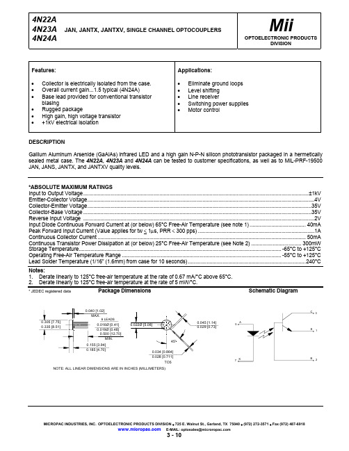
元器件交易网 4N22A, 4N23A, and 4N24A
JAN, JANTX, JANTXV, SINGLE CHANNEL OPTOCOUPLERS
*ELECTRICAL CHARACTERISTICS INPUT LED TA = 25°C Unless otherwise specified
4N22A
1
4N23A
IC(ON)
2.5
4N24A
4
On State Collector Current +100°C
4N22A
1
4N23A
IC(ON)
2.5
4N24A
4
Off State Collector Current Off State Collector Current
+25°C +100°C
V(BR)CBO
35
V(BR)CEO
35
V(BR)EBO
4
MAX
UNITS
V V V
TEST CONDITIONS
IC = 100µA, IB = 0, IF = 0 IC = 1mA, IB = 0, IF = 0 IC = 0, IE = 100µA, IF = 0
NOTE
*COUPLED CHARACTERISTICS TA = 25°C Unless otherwise specified
*ABSOLUTE MAXIMUM RATINGS Input to Output Voltage.............................................................................................................................................................±1kV Emitter-Collector Voltage..............................................................................................................................................................4V Collector-Emitter Voltage............................................................................................................................................................35V Collector-Base Voltage ...............................................................................................................................................................35V Reverse Input Voltage .................................................................................................................................................................2V Input Diode Continuous Forward Current at (or below) 65°C Free-Air Temperature (see note 1) ....................................... 40mA Peak Forward Input Current (Value applies for tw < 1µs, PRR < 300 pps) .................................................................................1A Continuous Collector Current ................................................................................................................................................. 50mA Continuous Transistor Power Dissipation at (or below) 25°C Free-Air Temperature (see Note 2) ................................... 300mW Storage Temperature............................................................................................................................................. -65°C to +125°C Operating Free-Air Temperature Range ............................................................................................................... -55°C to +125°C Lead Solder Temperature (1/16” (1.6mm) from case for 10 seconds) ..................................................................................240°C
VIPer22A应用中文资料
AN2097应用说明VIPower:采用VIPer22A的10W空调开关电源1. 摘要新的空调机采用两个主低压输出给内部电子设备供电。
这两个主输出的低压分别是+12V和+5V。
低输出电压是由一个内部开关电源产生。
这个开关电源需要以下多个重要特性:效率高,重量轻,尺寸小,待机功耗低等。
设计人员利用VIPerX2系列产品可以开发出一个含有所有这些重要功能的电源,因此,该系列产品是开发空调应用的最理想的解决方案,特别是下文介绍的电路板是为改进图1所示的特性而专门开发的,本文在表1列举的技术规格方面讨论了空调开关电源应用。
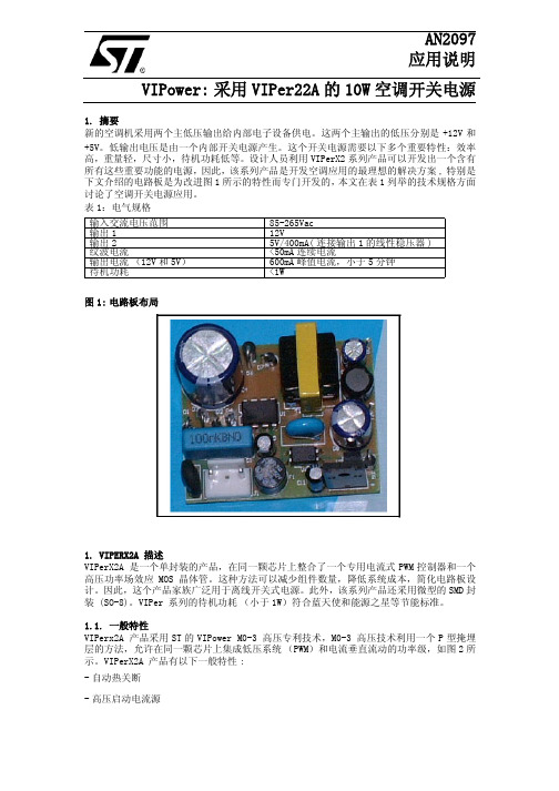
表1:电气规格图1:电路板布局1. VIPERX2A 描述VIPerX2A 是一个单封装的产品,在同一颗芯片上整合了一个专用电流式PWM控制器和一个高压功率场效应MOS晶体管。
这种方法可以减少组件数量,降低系统成本,简化电路板设计。
因此,这个产品家族广泛用于离线开关式电源。
此外,该系列产品还采用微型的SMD封装 (SO-8)。
VIPer 系列的待机功耗(小于1W)符合蓝天使和能源之星等节能标准。
1.1. 一般特性VIPerx2A 产品采用ST的VIPower M0-3 高压专利技术,M0-3 高压技术利用一个P型掩埋层的方法,允许在同一颗芯片上集成低压系统(PWM)和电流垂直流动的功率级,如图2所示。
VIPerX2A 产品有以下一般特性:-自动热关断-高压启动电流源输入交流电压范围85-265Vac输出112V输出25V/400mA(连接输出1的线性稳压器)纹波电流<50mA连续电流输出电流(12V和5V)600mA峰值电流,小于5分钟待机功耗<1W-防止输出短路导致击穿故障的打嗝(HICCUP)模式-保证低负载条件下低功耗的突发模式而且,VIPower M0-3技术还可用于开发最小击穿电压为730V 的功率场效应MOS 晶体管。
表2说明了该产品在不同的封装和工作条件下的功率处理能力。
2N2222A中文资料_数据手册_参数
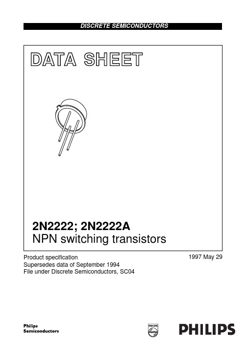
Objective specification Preliminary specification Product specification
This data sheet contains target or goal specifications for product development. This data sheet contains preliminary data; supplementary data may be published later. This data sheet contains final product specifications.
TO-18
1997 May 29
6
EUROPEAN PROJECTION
ISSUE DATE 97-04-18
Philips Semiconductors
NPN switching transistors
Product specification
2N2222; 2N2222A
DEFINITIONS
Data sheet status
SYMBOL
PARAMETER
Rth j-a Rth j-c
thermal resistance from junction to ambient thermal resistance from junction to case
CONDITIONS in free air
MIN.
MAX.
UNIT
−
60
Product specification
2N2222; 2N2222A
LIMITING VALUES In accordance with the Absolute Maximum Rating System (IEC 134).
1218B Audio Snake Cable 6-22 AWG 洁净铜对子, Datalene 保
Product:1218BAudio Snake Cable, #22-6pr, TC, Indiv. ShieldedProduct DescriptionAudio Snake Cable, 6-22 AWG tinned copper pairs, Datalene® insulation, individually shielded with Beldfoil® bonded to numbered/color-coded PVC jackets so both strip simulteaneously, flexible PVC jacketTechnical SpecificationsPhysical Characteristics (Overall)ConductorInsulationColor ChartInner ShieldInner JacketOuter JacketElectrical CharacteristicsConductor DCRCapacitance19 pF/ft35 pF/ftInductanceNominal Inductance0.2 µH/ftImpedanceNominal Characteristic Impedance70 OhmDelayNominal Velocity of Propagation (VP) [%]78%CurrentMax. Recommended Current [A]2 Amps per Conductor at 20ºCVoltageNon-UL Voltage Rating Voltage Rating [V]150 V RMS300 V RMS300 V RMSTemperature RangeNon-UL Temp Rating:60°COperating Temp Range:-20°C To +60°CMechanical CharacteristicsBulk Cable Weight:148 lbs/1000ftMax. Pull Tension:164 lbsMin. Bend Radius/Minor Axis: 5.75 inStandardsCPR Euroclass:EcaApplicable Environmental and Other Programs Environmental Space:Indoor (Not Riser or Plenum)EU Directive 2000/53/EC (ELV):YesEU Directive 2003/11/EC (BFR):YesEU Directive 2011/65/EU (RoHSYes2):EU Directive 2012/19/EUYes(WEEE):EU Directive 2015/863/EUYes(RoHS 2 amendment):EU Directive Compliance:EU Directive 2003/11/EC (BFR)EU CE Mark:YesMII Order #39 (China RoHS):YesSuitabilitySuitability - Indoor:YesFlammability, LS0H, Toxicity TestingIEC Flammability:IEC 60332-1-2Plenum/Non-PlenumPlenum (Y/N):NoRelated Part NumbersVariantsItem #Color Put-Up Type Length UPC 1218B B59500Black, Matte Reel500 ft6128251089931218B B591000Black, Matte Reel1,000 ft612825108986Footnote: C - CRATE REEL PUT-UP.Product NotesNotes:Datalene® insulation features include a low dielectric constant and a low dissipation factor for high-speed, low distortion data handling. Physical properties include good crush resistance and light weight. Pair jackets and shields are bonded so both strip simultaneously with automatic stripping equipment.HistoryUpdate and Revision:Revision Number: 0.366 Revision Date: 12-15-2021© 2022 Belden, IncAll Rights Reserved.Although Belden makes every reasonable effort to ensure their accuracy at the time of this publication, information and specifications described here in are subject to error or omission and to change without notice, and the listing of such information and specifications does not ensure product availability.Belden provides the information and specifications herein on an "ASIS" basis, with no representations or warranties, whether express, statutory or implied. In no event will Belden be liable for any damages (including consequential, indirect, incidental, special, punitive, or exemplary damages) whatsoever, even if Belden has been advised of the possibility of such damages, whether in an action under contract, negligence or any other theory, arising out of or in connection with the use, or inability to use, the information or specifications described herein.All sales of Belden products are subject to Belden's standard terms and conditions of sale.Belden believes this product to be in compliance with all applicable environmental programs as listed in the data sheet. The information provided is correct to the best of Belden's knowledge, information and belief at the date of its publication. This information is designed only as a general guide for the safe handling, storage, and any other operation of the product itself or the one that it becomes a part of. The Product Disclosure is not to be considered a warranty or quality specification. Regulatory information is for guidance purposes only. Product users are responsible for determining the applicability of legislation and regulations based on their individual usage of the product.。
詹姆斯·赫瓦森特雷尔卡斯特尔(0115400721)产品说明书
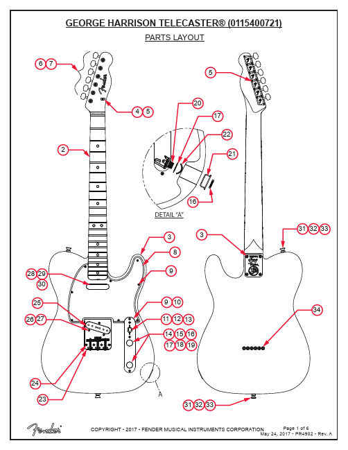
PARTS LAYOUTADETAIL “A”33232425271192357398410132630292812313433321918173231141615562017222116PARTS LISTREF#DESCRIPTION PARTNUMBER 1BODY GEORGE HARRISON SLD RW7710916521 2NECK ASSY GEORGE HARRISON ROSEWOOD7710810000 3SCREW SMA 8 X 1-3/4 OHP NI0015636049 4STRING TREE VINTAGE NI0994910000 5SCREW SMAB 3 X 3/8 RHP NI0011357049 6KEY GUITAR 70’S “F” RH CHROME W/HDWR0990822100 7BUSHING GUITAR KEYS 70’S0076555000 8PICKGUARD AM VINT 64 TELE B/W/B7700764000 9SCREW SMAB 4 X 1/2 OHP NI0015578049 10CONTROL PLATE TELE VINTAGE0093607000 11 3 WAY LEVER SWITCH 0038993000 12KNOB SWITCH TELE TOP HAT0994937000 13SCREW MA 6-32 X 5/8 RHP NI0015800049 14CONTROL KNOB KNURLED CHROME0991366000 15SET SCREW ST 8-32 X 3/160994922000 16NUT HEX 3/8-32 X 3/32 TK NI0016352049 17WASHER LOCKING INTL 3/8 X .6870016436049 18CONTROL 250K 10%0990831000 19CAPACITOR CD .05µF 50V0094251000 20JACK PHONE OPEN CIRCUIT 110021956049 21FERRULE JACK NICKEL 0991941000 22JACK RETAINER NI 0010355069 23BRIDGE ASSY 64 TELE VINT 0094026000 23A BRIDGE PLATE TELE PAT# 0058257000 23B BRIDGE SECTION VINT TELE THREADED0056038000 23C SPRING COMPRESSION 1-1/16 #1440018689049 23D SCREW ST 6-32 X 7/16 OVPT SL NI0016105049 23E SCREW M 6-32 X 1-1/4 RHP NI0015834000 23D SCREW ST 6-32 X 3/8 OVPT SL NI0016105049 24SCREW WOOD 6 X 1 OHP NI0037952049 25PICKUP ASSY 64 TELE BRDG0094008000 26TUBING LATEX CUT .375 X 1/8ID X 1/4OD0036878000 27SCREW M 6-32 X 5/8 RHP NI 0015800049*=NOT PICTURED IN DIAGRAMREF#DESCRIPTION PARTNUMBER 28PICKUP ASSY 64 TELE NK0094009000 29SCREW WOOD RND HD 3 X 3/4 NI0016311049 30TUBING LATEX CUT .550 X 1/80039410000 31SCREW WOOD 5 X 5/8 OHP NI0015602049 33STRAP BUTTON NI .1560994915000 34BLACK FELT WASHERS0994929000 35FERRULE STRING RETAINER NICKLE0994918000 *BRIDGE COVER CHROME TELE 0992271100 *CASE GTR 2012 AM VINT BLACK0094760000*=NOT PICTURED IN DIAGRAMWIRING ASSEMBLYNECK PICKUPBRIDGE PICKUPVOLUME CONTROLTONE CONTROLCAPACITOR .05µF BLACK & WHITEWIRE TO OUTPUT ASSY3 WAY SWITCH.05µFSWITCH AND CONTROL FUNCTION3 WAY SWITCH POSITION3 WAY SWITCHPOSITIONNECK PICKUPBRIDGE PICKUP321PICKUP IS ONOF 3 WAY SWITCHINDICATES POSITION 1PICKUP IS OFFFENDERPAT.NO.DES. 42272,5 254MASTER VOLUMEMASTER TONENECK PICKUPBRIDGE PICKUP3 WAY SWITCHADDITIONAL SPECIFICATION DETAIL.046”.103”2-7/16”.825”.975”8-32THREADØ.375”70’S “F” TUNING MACHINE SET W/HDWR P/N 0990822100OUTER SHAFT DIAMETER .375”TUNING MACHINE THRU-HOLEINNER DIAMETER .397”TRUSS ROD NUT P/N 0058171000SHORT: P/N 0094038000TALL: P/N 0016105049LOGO: 65 TELE NO PAT#APPLIED ON TOP OF FINISHSADDLE HEIGHT SET SCREWS SLOTTED 1ST FRET PROFILE12TH FRET PROFILENECK PROFILE: VINTAGE “U” SHAPEFRET SIZE: MEDIUM JUMBO(FRET DIMENSIONS ARE BEFORE INSTALLATION)Ø.397”Ø.375”PLEASE NOTE: AS EACH NECK IS SANDED & FINISHED BY HAND, THICKNESS DIMENSIONS MAY VARY SLIGHTLY FROMTHOSE SHOWN.PICKUP SPECIFICATIONSNECKBRIDGE DC RESISTANCE6.6 - 8.1KΩ5.4 - 6.6KΩMAGNETS ALNICO 5ALNICO 5POLARITYNORTHNORTHPOSITIONSLOTTED SET SCREW。
红的诱惑力HIIFMAN R2R2000的特别限量版

红的诱惑力HIIFMAN R2R2000的特别限量版
佚名
【期刊名称】《新潮电子》
【年(卷),期】2018(000)012
【摘要】针对2018年天猫的"双11"热卖季,阿里巴巴方面认为音频频道应该有一些热门的超人气产品参与,并提议将HIFIMAN产品中高流量的R2R2000纳入促销清单。
为此,HIFIMAN选择全新的PCM1702芯片制作了这款"双特别纪念版"红衣太子"R2R2000。
PCM1702与PCM1704类似,也是一款基于R2R架构的解码芯片。
虽然量化精度从PCM1704的24Bit变为20Bit,但音色极为相似,同样出色。
实际上,运用PCM1702芯片的世界级传奇名机不胜枚举,例如Accuphase金嗓子DP-75售价6300美元、柏林之声963售价10999美元,Linn Sondek莲CD-12售价20000美元以及Wadia怀念860的7450美元等,这充分佐证了PCM1702的硬实力与专业声誉,绝非浪得虚名。
【总页数】1页(P9-9)
【正文语种】中文
【中图分类】TN946.5
【相关文献】
1.再掀热潮——阿迪达斯再推三款Rose3限量版特别配色助力#罗斯归来# [J], Shopaholic
2.法拉利特别限量版超级跑车首发巴黎车展 [J],
3.SPEND0RS3/5R2SE黑檀木特别限量版书架箱 [J], 尧辰;小路
4.美学和声学的二元次方程HIFIMAN R2R2000太子红色特别版 [J],
5.HIFIMAN R2R2000红色特别版赏析 [J], 张臻(文/图)[1]
因版权原因,仅展示原文概要,查看原文内容请购买。
- 1、下载文档前请自行甄别文档内容的完整性,平台不提供额外的编辑、内容补充、找答案等附加服务。
- 2、"仅部分预览"的文档,不可在线预览部分如存在完整性等问题,可反馈申请退款(可完整预览的文档不适用该条件!)。
- 3、如文档侵犯您的权益,请联系客服反馈,我们会尽快为您处理(人工客服工作时间:9:00-18:30)。
on
off
40 35 250 300
ηs ηs
6 Lake Street, Lawrence, MA 01841 1-800-446-1158 / (978) 794-1666 / Fax: (978) 689-0803
120101 Page 2 of 2
hfe
2.5 25 50 35 75
hfe
Cobo Cibo
8.0 25
pF pF
SWITCHING CHARACTERISTICS
VCC = 30 Vdc; IC = 150 mAdc; IB1= 15 mAdc Turn-On Time 2N2218, 2N2219 (See Figure 3 of MIL-PRF-19500/251) 2N2218A, L, 2N2219A, L Turn-Off Time 2N2218, 2N2219 (See Figure 4 of MIL-PRF-19500/251) 2N2218A, L, 2N2219A, L (3) Pulse Test: Pulse Width = 300µs, Duty Cycle ≤ 2.0%.
120 300
VCE(sat)
0.4 0.3 1.6 1.0 0.6 0.6 1.3 1.2 2.6 2.0 12
Vdc
VBE(sat)
Vdc
DYNAMIC CHARACTERISTICS
Magnitude of Small-Signal Forward Current Transfer Ratio IC = 20 mAdc, VCE = 20 Vdc, f = 100 MHz Small-Signal Forward Current Transfer Ratio IC = 1.0 mAdc, VCE = 10 Vdc, f = 1.0 kHz 2N2218 2N2219 2N2218A, L 2N2219A, L Output Capacitance VCB = 10 Vdc, IE = 0, 100 kHz ≤ f ≤ 1.0 MHz Input Capacitance VEB = 0.5 Vdc, IC = 0, 100 kHz ≤ f ≤ 1.0 MHz
元器件交易网
TECHNICAL DATA
NPN SWITCHING SILICON TRANSISTOR
Qualified per MIL-PRF-19500/251 Devices 2N2218 2N2218A 2N2218AL 2N2219 2N2219A 2N2219AL Qualified Level JAN JANTX JANTXV JANS
MAXIMUM RATINGS Ratings
Collector-Emitter Voltage Collector-Base Voltage Emitter-Base Voltage Collector Current Total Power Dissipation @ TA = +250C(1) @ TC = +250C(2) Operating & Storage Junction Temp. Range
IEBO
µAdc ηAdc
ICES
ηAdc
6 Lake Street, Lawrence, MA 01841 1-800-446-1158 / (978) 794-1666 / Fax: (978) 689-0803
120101 Page 1 of 2
元器件交易网
2N2218; A; AL; 2N2219; A; AL JAN SERIES
ICBO
ON CHARACTERISTICS (3)
Forward-Current Transfer Ratio IC = 0.1 mAdc, VCE = 10Vdc 2N2218 2N2219 2N2218A; 2N2218AL 2N2219A; 2N2219AL 2N2218 2N2219 2N2218A; 2N2218AL 2N2219A; 2N2219AL 2N2218 2N2219 2N2218A; 2N2218AL 2N2219A; 2N2219AL 2N2218; A; 2N2218AL 2N2219; A; 2N2219AL 2N2218; A; 2N2218AL 2N2219; A; 2N2219AL 2N2218; 2N2219 2N2218A; L; 2N2219A; L 2N2218; 2N2219 2N2218; L; 2N2219A; L 2N2218; 2N2219 2N2218A; L, 2N2219A, L 2N2218; 2N2219 2N2218A; L; 2N2219A; L 20 35 30 50 25 50 35 75 35 75 40 100 40 100 20 30
Symbol
VCEO VCBO VEBO IC PT Top, Tstg
2N2218 2N2219
30 60 5.0
2N2218A; L 2N2219A; L
50 75 6.0
Unit
Vdc Vdc Vdc mAdc W W 0 C Unit C/W
800 0.8 3.0 -55 to +200 Max. 59
0
TO-5*
2N2218AL, 2N2219AL
*See appendix A for package outline
ELECTRICAL CHARACTERISTICS (TA = 250C unless otherwise noted)
Characteristics Symbol Min. Max. Unit
OFF CHARACTERISTICS
Collector-Emitter Breakdown Voltage IE = 10 mAdc Emitter-Base Cutoff Current VEB = 5.0 Vdc VEB = 6.0 Vdc VEB = 4.0 Vdc Collector-Base Cutoff Current VCE = 30 Vdc VCE = 50 Vdc 2N2218; 2N2219 2N2218A; L; 2N2219A; L 2N2218; 2N2219 2N2218A; L; 2N2219A; L All Types 2N2218; 2N2219 2N2218A; L; 2N2219A; L V(BR)CEO 30 50 10 10 10 10 10 Vdc
ELECTRICAL CHARACTERISTICS (con’t)
Characteristics Collector-Base Cutoff Current VCB = 50 Vdc 2N2218; 2N2219 VCB = 60 Vdc 2N2218A; L; 2N2219A; L VCB = 60 Vdc 2N2218; 2N2219 VCB = 75 Vdc 2N2218A; L, 2N2219A; L Symbol Min. Max. 10 10 10 10 Unit ηAdc µAdc
TO- 39* (TO-205AD) 2N2218, 2N2218A 2N2219, 2N2219A
THERMAL CHARACTERISTICS
Characteristics Symbol Thermal Resistance, Junction-to-Case RθJC 1) Derate linearly 4.6 mW/0C above TA > +250C 2) Derate linearly 17.0 mW/0C above TC &0 Vdc
hFE
150 325 150 325
IC = 10 mAdc, VCE = 10 Vdc
IC = 150 mAdc, VCE = 10 Vdc IC = 500 mAdc, VCE =10 Vdc Collector-Emitter Saturation Voltage IC = 150 mAdc, IB = 15 mAdc IC = 500 mAdc, IB = 50 mAdc Base-Emitter Saturation Voltage IC = 150 mAdc, IB = 15 mAdc IC = 500 mAdc, IB = 50 mAdc
