基于灭点的图像处理
图像处理技术的原理及实践例子
图像处理技术的原理及实践例子随着计算机科学的快速发展,图像处理技术作为其重要的分支之一也得到了迅猛发展。
图像处理技术是指利用计算机进行对图像的处理、分析和识别。
在图像处理技术中,数字图像的获取、处理和显示是一个完整的过程。
数字图像可以通过机器视觉系统、数字相机和扫描仪等设备获取。
数字图像可以表示成矩阵形式,其中每个像素点代表一个数字。
通过对图像中像素点数值进行处理,可以使图像获得不同的效果。
下面我们就来了解一些图像处理技术的原理及实践例子。
1. 图像锐化处理技术图像锐化处理技术是指在数字图像的处理过程中增强图像的轮廓和细节,使图像更加清晰。
图像锐化处理技术实现的原理主要是通过卷积运算进行的。
卷积运算是将数字图像和一个卷积核进行相乘后相加的数学运算。
卷积核是一个矩阵,卷积运算可以使数字图像的每个像素点与周围的像素点相加后取平均值,从而得到更清晰的图像。
实践例子:滤波器法和锐化滤波器法。
①滤波器法:滤波器法在图像处理中是一种常用的方法。
它的处理过程是利用低通滤波器对图像进行模糊处理,然后再用高通滤波器对图像进行锐化处理,最终得到一张更加清晰的图像。
②锐化滤波器法:锐化滤波器法是一种可以增强图像中各点的细节,并提高其清晰度的图像处理方法。
这种方法通常通过在数字图像中加入高通滤波器,以达到增强图像轮廓和细节的目的。
2. 图像边缘检测图像边缘检测是指在数字图像中有针对性地检测边缘,并对图像进行分割和提取。
常用的边缘检测算法有Canny算法、Sobel算法和Laplacian算法等。
在这些算法中,Sobel算法是应用最广泛的一种。
Sobel算法的原理是通过提取图像中不同方向上的像素点变化量,以实现图像分割和边缘检测的目的。
Sobel算法可以根据不同的方向进行边缘检测,对于在垂直方向上的较长边缘可以采用水平Sobel滤波器,而对于在水平方向上的较长边缘可以采用垂直Sobel滤波器。
实践例子:用Sobel算子实现图像边缘检测。
如何使用图像处理技术进行图像去模糊处理

如何使用图像处理技术进行图像去模糊处理图像去模糊处理是一项常见的图像处理任务,它可以提高图像的清晰度和细节,并改善图像的视觉质量。
在本文中,我们将介绍一些常用的图像处理技术,帮助您有效地去除模糊,使图像更加清晰。
了解图像模糊的原因对于进行有效的图像去模糊处理至关重要。
图像模糊通常是由于相机晃动、主体运动或镜头不聚焦等因素导致的。
根据模糊的原因,我们可以选择不同的图像处理方法。
一种常见的图像去模糊处理方法是使用图像霍夫变换(IHT)来估计模糊核。
图像霍夫变换可以帮助我们理解和分析图像中的直线、圆形、椭圆形等形状。
通过将图像转换为霍夫空间,我们可以找到对应于图像模糊的潜在模糊核。
我们可以利用找到的模糊核来进行图像去模糊处理。
另一种常用的图像去模糊处理方法是使用盲复原算法。
这种方法不需要事先知道模糊核的大小和形状,而是通过对图像进行反卷积来估计模糊核和原始图像。
盲复原算法基于图像的统计特性和先验知识来恢复模糊的图像。
这种方法在处理复杂的图像模糊时往往比较有效。
除了上述的方法,我们还可以使用一些常见的图像增强技术来改善图像的清晰度。
例如,锐化滤波器可以增强图像的边缘和细节,减少图像的模糊。
锐化滤波器可以通过增强高频分量或降低低频分量来实现。
还有一些其他的图像增强技术,如非锐化掩蔽(USM)、双边滤波(Bilateral Filter)等,它们都可以帮助我们提高图像的清晰度和细节。
在使用图像处理技术进行图像去模糊处理时,我们还应该注意一些常见的注意事项。
要根据图像的模糊程度选择合适的处理方法。
对于轻微模糊的图像,简单的滤波器可能就足够了,而对于严重模糊的图像,则可能需要更复杂的处理方法。
要注意图像去模糊处理过程中可能产生的图像伪影或噪点。
这些伪影和噪点可能会降低图像的质量,因此我们需要在处理过程中进行适当的去除或减少。
总之,图像去模糊处理是一项重要的图像处理任务,可以大大改善图像的质量和细节。
在处理图像模糊时,我们可以选择合适的图像处理技术,如图像霍夫变换、盲复原算法和图像增强技术等。
图像处理的方法有哪些

图像处理的方法有哪些
图像处理的方法包括但不限于以下几种:
1. 滤波:通过卷积操作对图像进行模糊、边缘检测、锐化等处理,常见的滤波方法有均值滤波、高斯滤波、中值滤波等。
2. 灰度变换:通过对图像的像素值进行线性或非线性函数变换,改变图像的对比度、亮度或色调。
3. 直方图均衡化:通过对图像的像素值进行重新分布,使得图像的灰度直方图更均匀,增强图像的对比度。
4. 缩放与旋转:改变图像的尺寸和角度,常见的方法包括最近邻插值、双线性插值和双三次插值。
5. 边缘检测:通过寻找图像中亮度变化较大的像素点,检测图像的边缘。
常见的边缘检测算法有Sobel算子、Prewitt算子和Canny算子。
6. 分割:将图像分成若干个相互独立的区域,常见的方法有阈值分割、基于区域的分割和基于边缘的分割。
7. 特征提取:从图像中提取出具有代表性的特征,常见的特征包括形状特征、
纹理特征和颜色特征。
8. 目标检测与识别:在图像中检测和识别出特定的目标,常见的方法有模板匹配、Haar特征和深度学习等。
9. 图像修复与增强:对受损的图像进行修复,消除图像中的噪声、模糊和伪影等,提高图像的质量。
10. 图像压缩与编码:对图像进行压缩,减少图像占用的存储空间,常见的压缩算法有JPEG、PNG和GIF等。
这些方法可以单独应用于图像处理,也可以组合使用以实现更复杂的图像处理任务。
10个图像处理技术的实际应用案例

10个图像处理技术的实际应用案例图像处理技术在当今社会中已经得到了广泛的应用,无论是在科研领域、医学诊断、影视制作还是智能交通等领域都发挥着重要的作用。
以下是10个图像处理技术的实际应用案例。
人脸识别技术。
这项技术可以通过图像识别出人脸特征,并与数据库中的信息进行对比,用于安全门禁、人脸支付、社交媒体的面部标记等。
虚拟现实技术。
基于图像处理技术,虚拟现实可以模拟出逼真的虚拟世界,广泛应用于游戏制作、建筑设计、医学培训等领域。
第三,医学图像处理技术。
医学领域借助这一技术可以对CT、MRI等图像进行处理,辅助医生进行疾病诊断和手术规划,提高了医疗质量和效率。
第四,图像压缩技术。
这项技术可以减少图像的存储空间和传输带宽,广泛应用于图像和视频的传输和存储中,如图像传真、图像存储等。
第五,图像修复技术。
该技术可以通过图像处理算法修复破损、受损或补全的图像,被广泛运用于文物修复、图像恢复等领域。
第六,图像分割技术。
图像分割技术可以将图像分成若干区域,常用于图像识别、目标检测等领域,如自动驾驶、智能机器人等。
第七,图像增强技术。
该技术可以通过增加图像的对比度、亮度、锐度等来提高图像的质量和可视化效果,广泛应用于图像美化、摄影后期处理等领域。
第八,图像识别技术。
基于图像处理技术,图像识别可以识别出图像中的物体、文字等,并进行分析和识别,广泛应用于智能搜索、自动驾驶、人脸识别等领域。
第九,图像融合技术。
该技术可以将多幅图像融合成一幅图像,常用于遥感图像、医学图像等领域,如遥感影像的特征提取、多模态医学影像的融合等。
图像超分辨率技术。
该技术可以通过图像处理方法提高图像的分辨率,常用于监控视频、数字摄影等领域,如安全监控中的行人特征提取、卫星图像的解析度提升等。
综上所述,图像处理技术在多个领域中都有着广泛的应用。
随着技术的不断发展,相信图像处理技术将在未来带来更多的创新和应用案例。
图像处理中的图像去噪算法使用方法
图像处理中的图像去噪算法使用方法图像去噪算法是图像处理领域的一个重要研究方向,它的主要目标是通过消除或减少图像中的噪声,提高图像的视觉质量和信息可读性。
图像噪声是由于图像信号的获取、传输和存储过程中引入的不可避免的干扰所致,例如传感器噪声、电磁干扰等,使图像中的细节模糊,影响图像的清晰度和准确性。
因此,图像去噪算法在许多应用领域中都具有重要的意义,如医学图像处理、计算机视觉、图像识别等。
现在,我们将介绍几种常见的图像去噪算法及其使用方法。
1. 中值滤波算法:中值滤波算法是一种简单而有效的图像去噪方法。
它的基本原理是对图像中的每个像素点周围的邻域进行排序,然后取中间值作为该像素点的输出值。
中值滤波算法适用于去除椒盐噪声和脉冲噪声,它能够保持图像的边缘和细节信息。
使用中值滤波算法时,需要设置一个邻域大小,根据该大小确定图像中每个像素点周围的邻域大小。
较小的邻域大小可以去除小型噪声,但可能会丢失一些细节信息,较大的邻域大小可以减少噪声,但可能会使图像模糊。
2. 均值滤波算法:均值滤波算法是一种基本的线性滤波技术,它的原理是计算图像中每个像素点周围邻域像素的平均值,并将平均值作为该像素点的输出值。
均值滤波算法简单易实现,适用于消除高斯噪声和一般的白噪声。
使用均值滤波算法时,同样需要设置邻域大小。
相较于中值滤波算法,均值滤波算法会对图像进行平滑处理,减弱图像的高频细节。
3. 降噪自编码器算法:降噪自编码器算法是一种基于深度学习的图像去噪算法。
它通过使用自编码器网络来学习图像的特征表示,并借助重建误差来去除图像中的噪声。
降噪自编码器算法具有较强的非线性建模能力,可以处理复杂的图像噪声。
使用降噪自编码器算法时,首先需要训练一个自编码器网络,然后将噪声图像输入网络,通过网络进行反向传播,优化网络参数,最终得到去噪后的图像。
4. 小波变换去噪算法:小波变换去噪算法是一种基于小波分析的图像去噪算法。
它将图像分解为不同尺度下的频域子带,通过对各个子带进行阈值处理来消除图像中的噪声。
图形图像处理第四版第三章课后题答案

图形图像处理第四版第三章课后题答案一、填空题(每空1分,共30分)1、计算机图形学是用计算机建立、存储、处理某个对象的模型,并根据模型产生该对象图形输出的有关理论、方法与技术。
2、计算机图形系统功能主要有计算功能、存储功能、输入功能、输出功能、交互功能。
3、区域的表示有内点表示和边界表示两种形式。
4、字符裁剪的策略有串精度裁剪、字符精度裁剪、基于构成字符最小元素的裁剪。
5、图形软件系统提供给用户的三种基本输入方式包括请求方式、采样方式、事件方式。
6、常见的图形绘制设备有喷墨打印机、笔式绘图机、激光打印机。
7、字符生成常用的描述方法有点阵式和轮廓式。
8、在交互式图形输入过程中,常用的控制方式有请求、样本、事件和混合四种形式。
9、用于八连通区域的填充算法可以用于四连通区域的填充,但用于四连通区域的填充算法并不适用于八连通区域的填充。
10、能够在人们视觉系统中形成视觉印象的对象称为图形。
二、不定项选择题(每题2分,共20分)1、计算机图形显示器一般使用(A)颜色模型。
(A)RGB (B) CMY(C)HSV (D) HLS2、计算机图形系统功能不包括(D)。
(A)计算功能(B) 存储功能(C)交互功能(D)修饰功能3、多边形填充算法中,正确的描述是(ABC)(A)扫描线算法对每个象素只访问一次,主要缺点是对各种表的维持和排序的耗费较大(B)边填充算法基本思想是对于每一条扫描线与多边形的交点,将其右方象素取补(C)边填充算法较适合于帧缓冲存储器的图形系统(D)边标志算法也不能解决象素被重复访问的缺点4、在交互式图形输入过程中,常用的控制方式不包括(C)。
(A)样本(B)事件(C)交互(D)混合5、下列有关平面几何投影的叙述,错误的是(D )(A)透视投影又可分为一点透视、二点透视、三点透视(B)斜投影又可分为斜等测、斜二测(C)正视图又可分为主视图、侧视图、俯视图(D)正轴测又可分为正一测、正二测、正三测6、视频信息的最小单位是(A )(A)帧(B)块(C)像素(D)字7、在透视投影中,主灭点的最多个数是(C)(A)1(B)2(C)3(D)48、扫描线多边形填充算法中,对于扫描线同各边的交点的处理具有特殊性。
基于消失点的鲁棒逆透视变换

基于消失点的鲁棒逆透视变换重庆大学硕士学位论文(学术学位)学生姓名:张代明指导教师:房斌教授专业:计算机应用技术学科门类:工学重庆大学计算机学院二O一五年四月Robust Inverse Perspective Mapping Based on Vanishing PointA Thesis Submitted to Chongqing UniversityIn Partial Fulfillment of the Requirement for theMaster’s Degree of EngineeringByZhang DaimingSupervised by Prof. Fang BinSpecialty:Computer Application TechnologyCollege of Computer Science ofChongqing University, Chongqing, ChinaApril 2015摘要逆透视变换在计算机视觉和道路交通标志检测和识别方面得到了广泛的应用。
逆透视变换是透视变换的逆过程,主要是结合相机的内在和外在参数,将图像从图像坐标系映射到世界坐标系,从而消除透视影响对图像检测和识别任务的干扰和误差。
因此,鲁棒的逆透视变换对于透视影响的消除和获取图像信息的不变量有着非常重要的作用。
本文主要研究了基于消失点的鲁棒逆透视变换及其应用,采用消失点对逆透视变换需要的部分偏转角度参数进行了自动计算,并将逆透视变换应用到导向箭头的检测和识别任务中。
首先,本文介绍了基于消失点的鲁棒逆透视变换的选题背景以及研究意义,总结了现有逆透视变换算法的国内外研究现状以及存在的难点问题。
其次,本文介绍了逆透视变换的基本概念及其数学原理,总结了逆透视变换在道路交通标线检测的广泛应用,并对常见逆透视变换方法进行了分类总结。
从基于点变换的逆透视变换、基于矩阵变换的逆透视变换和基于简化相机模型推导的逆透视变换三个方面介绍了现有逆透视变换的优点和缺点。
如何利用图像处理技术改善低光照条件下的图像

如何利用图像处理技术改善低光照条件下的图像低光照条件下的摄影是摄影爱好者和专业摄影师所面临的一项常见挑战。
图像在暗处存在噪点,细节模糊,以及低对比度等问题。
然而,借助图像处理技术,我们可以改善低光照条件下的图像,提高图像的质量。
1. 直方图均衡化直方图均衡化是一种常用的图像增强技术,通过调整图像的像素值分布来改善图像的对比度。
在低光照条件下,图像的对比度通常较低。
通过直方图均衡化算法,我们可以增强图像中的暗部细节,并提高图像的整体对比度。
这能够使图像变得更加清晰和明亮。
2. 去噪处理低光照条件下的图像容易出现噪点,导致图像细节模糊。
为了解决这个问题,我们可以应用图像去噪处理技术,在保持图像细节的同时降低噪声水平。
常见的去噪方法包括中值滤波、高斯滤波和小波去噪等。
这些算法可以有效地减少图像中的噪点,使图像看起来更清晰。
3. 增加局部对比度低光照条件下的图像常常使得图像的细节不够清晰,无法准确表达物体的纹理。
一种应对方法是增加图像的局部对比度。
通过应用局部对比度增强算法,我们可以放大图像中的细节,突出图像中的边缘和纹理。
这能够使图像看起来更加锐利,同时提高图像中物体的可视化效果。
4. 调整亮度和色调低光照条件下的图像往往过暗,色调不准确。
通过调整图像的亮度和色调,我们可以改善图像的整体感觉和视觉效果。
亮度调整可以使图像变得更明亮,色调调整可以纠正图像中的色彩偏差。
这两个调整可以帮助我们更好地展示图像中的细节,并使图像看起来更加自然。
5. 多帧合成多帧合成是一种通过合并多个曝光不同的图像来增强图像质量的方法。
在低光照条件下,通过在不同曝光时间下拍摄多张图像,我们可以获得具有更广泛动态范围的图像。
通过图像融合算法,我们可以将这些图像合成为一张高质量的图像。
这种方法能够提高图像的细节和纹理,并减少图像中的噪点。
总结起来,利用图像处理技术可以有效地改善低光照条件下的图像。
通过直方图均衡化、去噪处理、增加局部对比度、调整亮度和色调、以及多帧合成等方法,我们可以提高图像的对比度、清晰度和细节,并使图像更加自然和具有吸引力。
retinex算法实例
retinex算法实例一、Retinex算法简介1.背景介绍Retinex算法是一种基于神经网络的图像处理算法,由美国科学家Edwin nd于1986年提出。
该算法主要针对图像的视觉质量改善,具有较强的实用价值。
2.算法原理Retinex算法的基本思想是通过神经网络学习原始图像和处理后图像之间的映射关系,从而实现对图像的改善。
算法主要分为两个阶段:训练阶段和应用阶段。
在训练阶段,Retinex算法通过大量原始图像和处理后图像对神经网络进行训练,学习到一个合适的映射关系。
在应用阶段,神经网络将输入的原始图像映射到处理后图像,从而实现图像的改善。
二、Retinex算法实例1.图像去噪Retinex算法广泛应用于图像去噪领域,可以有效去除图像中的噪声,恢复图像的原始细节。
例如,在医学图像处理中,去除噪声后的图像有助于医生更准确地诊断疾病。
2.图像增强Retinex算法还可以用于图像增强,提高图像的视觉质量。
例如,在夜景拍摄中,通过对原始图像进行增强处理,可以获得更为清晰的夜景照片。
3.图像超分辨率重建Retinex算法还可以用于图像超分辨率重建,即将低分辨率图像重建为高分辨率图像。
这一应用在视频监控、遥感图像等领域具有重要意义。
三、Retinex算法应用1.去雾霾Retinex算法在去雾霾方面具有显著效果。
通过对雾霾图像进行处理,可以还原出清晰的远景,使图像质量得到显著提高。
2.夜景拍摄Retinex算法在夜景拍摄中的应用可以帮助摄影师获得更为清晰的夜景照片。
通过对原始图像进行处理,可以有效降低噪声,提高图像的亮度和对比度。
3.医学图像处理Retinex算法在医学图像处理领域具有重要意义。
通过对医学图像进行去噪和增强处理,有助于医生更准确地诊断疾病。
四、算法优缺点分析1.优点Retinex算法具有以下优点:(1)具有较强的去噪能力,可以有效去除图像中的噪声;(2)能够提高图像的视觉质量,使图像更加清晰;(3)适用于多种图像处理任务,如去雾、增强、超分辨率重建等。
园林制图第四章灭点法作建筑透视

灭点法的基本原理
01
02
03
选择适当的灭点
在选择灭点时,需要考虑 建筑物的形状、方向和观 察者的位置等因素,以确 定最佳的灭点位置。
计算透视比例尺
根据建筑物的大小和观察 距离,计算透视比例尺, 以确定建筑物各部分的大 小和位置。
绘制透视图
根据所选的灭点和透视比 例尺,使用绘图工具绘制 建筑物的透视图。
保持透视图的平衡和稳定
在绘制透视图时,应注意画面的平衡和稳定,避免过于倾 斜或扭曲的构图。
准确把握比例关系
建筑透视的比例关系非常重要,应准确把握建筑、配景、 人物等元素之间的比例关系,确保画面和谐统一。
注意画面的层次感和空间感
通过合理的构图和比例关系,表现出画面的层次感和空间 感,使画面更加立体和生动。
保持线条的流畅和自然
在绘制透视图时,应尽量保持线条的自然和流畅,避免生硬和机 械化的线条。
正确处理光影关系
为了增强透视图的真实感,需要正确处理建筑的光影关系,表现出 建筑的立体感和质感。
合理运用色彩和调色
色彩的运用对于增强透视图的真实感也非常重要,应合理运用色彩 和调色技巧,使画面更加生动和真实。
注意透视图的构图和比例
设计更加高效。
在建筑透视中的应用
建筑外观表现
灭点法常用于建筑外观透视图的 绘制,通过确定建筑物的透视关 系,表现出建筑物的立体感和空
间感。
室内设计表现
在室内设计中,灭点法可以帮助设 计师绘制室内透视效果图,预见室 内空间的实际效果,为室内设计提 供有力支持。
建筑规划展示
在建筑规划和设计方案展示中,灭 点法可以用来绘制建筑物的透视图, 使规划方案更加直观地呈现给观众。
03
基于图像处理的火灾自动检测系统设计

基于图像处理的火灾自动检测系统设计火灾作为一种常见的灾害,给人们的生命和财产安全带来了巨大的威胁。
为了提高火灾事故的防范和处理能力,设计一个基于图像处理的火灾自动检测系统具有重要的意义。
本文将从系统需求、系统架构、图像处理算法以及系统性能评估等方面进行论述。
一、系统需求火灾自动检测系统设计的首要任务是实现火灾的快速检测和准确识别。
系统需要具备以下几个主要的功能:1. 实时监测:能够对监控区域进行持续的实时监测,及时发现火灾隐患。
2. 图像采集:能够获取高质量、高分辨率的监控图像,并存储为数字图像。
3. 图像预处理:对采集到的图像进行预处理,包括去噪、图像增强等,以提高后续图像处理算法的准确性和鲁棒性。
4. 火灾特征提取:利用图像处理算法,从监控图像中提取火灾的特征,例如火光、烟雾等。
5. 火灾识别:通过比对提取到的特征与预设的火灾特征库,实现火灾的自动识别。
二、系统架构基于图像处理的火灾自动检测系统可以分为硬件和软件两个部分。
硬件部分主要包括监控摄像头、图像采集设备和存储设备,软件部分主要包括图像预处理模块、火灾特征提取模块和火灾识别模块。
系统的工作流程如下:1. 摄像头采集监控图像,并传输给图像采集设备。
2. 图像采集设备对图像进行数字化处理,并存储为数字图像。
3. 图像预处理模块对采集到的图像进行预处理,包括去噪、图像增强等。
4. 火灾特征提取模块利用图像处理算法,从预处理后的图像中提取火灾的特征。
5. 火灾识别模块将提取到的特征与预设的火灾特征库进行比对,实现火灾的自动识别。
三、图像处理算法图像处理算法是实现火灾自动检测的关键。
常见的图像处理算法包括背景建模、光流法、颜色分析、形状分析等。
1. 背景建模:通过建立图像序列的背景模型,检测运动目标。
火灾时,由于火焰和烟雾的存在,图像序列的背景会发生较大的变化,通过背景建模可以检测到这些变化,进而判断是否发生火灾。
2. 光流法:通过分析图像中的运动信息,判断是否存在火焰和烟雾的运动轨迹。
基于物体几何性质的单幅图像三维重建
为 代表 的 , 此方法 能够 获取 物体 的精 确模 型 , 但 是设 备 昂贵 、 通用 性 差 ; 被动 方 法是 指 基 于 图像 的 三维 重建 , 此 种方 法相 对 而言具 有成本 低 、 灵活 等特 点 , 能 得 到照片 级真 实感模 型且 应用 广 。基 于 图像 的三维 重建 可分
三维重 建技 术一 直是计 算 机视觉 和计 算机 图形 学研 究 的热点 , 在虚 拟现 实 、 城 市数字 化 、 文物古 迹恢 复 、
医学 等领域 具有 广泛 的应 用 。现在 已经有 一些 成熟 的软件 ( 比如 3 DMAX 和 Ma y a等 ) 可 实 现 手动 重 建 , 但 是 此种 方法 需要 繁琐 的人工 操作 , 因此 如何 从现 实世 界 中直 接快 速 获得 物 体 的三 维结 构 成 为人 们 的研 究 热
基金项 目: 国家 自然 科 学 基 金 项 目( 6 1 1 7 0 1 0 6 ) , 青 岛市 科 技 计 划 项 目基 金 ( 0 6 — 2 — 2 — 2 一 J C)
作者简介 : 石仁爱( 1 9 8 7 一 ) , 女, 山东 省 , 泰安市人 , 硕 士 研究 生 , 主要 研 究 方 向 : 图 像 处 理 与 计 算 机 视觉 。
Op e n GL实现 三维重 建 和纹理 映射 。实验 表 明 , 此 方法 可恢 复出 目标物体 的精确 三 维结 构 ,
能够 满 足一般 虚拟 现实 的需要 。
关 键词 : 单 幅未标 定 图像 ; 消失点 ; 相 机标定 ; 物 体几何 性 质 ; 三 维重建
基于OpenCV的机器视觉图像处理技术实现
基于OpenCV的机器视觉图像处理技术实现机器视觉是计算机科学领域中涉及图像处理、模式识别以及计算机视觉的一个探究领域。
近年来,随着计算机技术的快速进步,机器视觉在工业、医疗、军事等领域得到了广泛应用。
在机器视觉中,图像处理是一个基础而重要的环节,它能够对图像进行预处理、分析和处理,从而为后续的模式识别和计算机视觉任务提供有效的基础。
在图像处理领域,OpenCV是一个分外流行和强大的开源库。
它提供了丰富的图像处理功能,包括图像的读取、显示、保存,以及各种滤波器、边缘检测、图像增强等算法。
本文将介绍基于OpenCV的机器视觉图像处理技术的实现方法和应用案例。
一、图像预处理图像预处理是图像处理中的第一步,它主要用于提取图像中的有用信息、消除图像中的噪声、调整图像的亮度和对比度等。
在OpenCV中,可以使用不同的方法进行图像的预处理,如灰度化、二值化、直方图均衡化等。
1. 灰度化灰度化是将彩色图像转换为灰度图像的过程。
在机器视觉中,由于灰度图像只有一个通道,处理起来更加高效。
在OpenCV中,可以使用cvtColor函数将彩色图像转换为灰度图像。
2. 二值化二值化是将灰度图像转化为二值图像的过程。
将图像中的每个像素值与一个阈值进行比较,大于阈值的像素设置为255,小于阈值的像素设置为0。
在OpenCV中,可以使用threshold 函数实现图像的二值化。
3. 直方图均衡化直方图均衡化是一种调整图像亮度和对比度的方法。
它通过重新分布图像的像素值来增强图像的细节。
在OpenCV中,可以使用equalizeHist函数实现直方图均衡化。
二、特征提取特征提取是机器视觉中的一个重要环节,它通过从图像中提取有用的特征信息,为后续的模式识别和计算机视觉任务提供基础。
在OpenCV中,可以使用各种特征提取算法,如HOG、SIFT和SURF等。
1. HOG特征提取HOG(Histogram of Oriented Gradients)是一种用于目标检测和行人识别的特征提取算法。
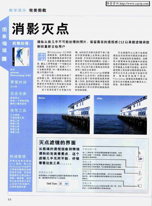
消影灭点
篓 :
我 们 将 陆 续 向 读 者 推 出 以 下 内容 … …
探 索 如何 将 日常 片 转化 成令 人 麓撼 的 红外 缝风 景 我 们的 深 度 演示 内窖 远远 超 出基 础知 识 一 保证读 者 能将 自 的 作品 处 理到专 业水 准 初 揉C r 1 o e 公 新版 本的P 1 d 吐
令 ,戢 后自 面 的后 方拖 动选 择 内窖 它 就会 在穆 动的 同时
自 行调整 “适 台画面
起 是 衣 工 翦 到 创 考 镱
Sh 9 o Pr Ph o ^1 um o Ot b 6软
件 我 们组 成 7一 队 自大褂 人 员 ,从 选一 巧软 件的 开发 商 那 里直 接为 读者 带采 简 明易 懂 的学 习教 程
稽 们 E 经 近 放 太 到 蹴 柱 的
头.井 且追 踪构 造的 透视 结构 制 7一十 日角 的网 格. 目 出 T屋面 域 在 目标 的附 近点 击 鼠标 米 放 口 点 ” 然 后
Ph oD胤 可 0t h Os 接 您 艘 目 的 点 . 根 据 所 选 择 的 i 来 生 或 成 同格
和 3维 的 立 体 目 形 面创 建I具 追踪 对象 的透视 关系 .
化 和 模 糊 等 纂 单 项 中 就 会 现 祥 新 增 的 东
西 . 让^好 奇的 是一个 叫做 点 最 的滤 镜 点击 选中它 . 进^ T一 就 个 ±新 的界面 咋一 看还 真有 点儿 强 力可畏 的气 势
IE mn ∞
:
I^一 w L——————— 一
6 6
维普资讯
完 美 剪 裁
延 展 构 造 并 保 持 透 视 关 系
伸 直线 条
消失点工具的使用方法
消失点工具的使用方法消失点工具是一种常用于数字图像处理的工具,用于消除图像中的噪声、瑕疵、模糊等问题,提高图像的质量和清晰度。
在本文中,我将详细介绍消失点工具的使用方法。
消失点工具是一种基于图像处理算法的工具,它可以通过计算图像中的像素点之间的关联性,来修复图像中的问题,并还原图像的细节和清晰度。
下面是使用消失点工具的详细步骤:1. 打开图像处理软件,并导入需要修复的图像。
这些软件可以是Photoshop、GIMP、Lightroom等常见的图像处理软件。
2.定位图像中的问题区域。
通过放大、缩小图像,或者使用魔术棒工具、套索工具等选择工具,来准确定位要修复的问题区域。
3. 选择消失点工具。
这些工具通常可以在图像处理软件的工具栏中找到,有时被称为修复刷、修复工具、修复画笔等等。
4. 调整消失点工具的参数。
不同的图像处理软件提供了各种参数选项,可以根据实际需求进行调整。
常见的参数包括笔刷大小、采样区域、混合模式等。
5. 使用消失点工具修复问题区域。
小心地在问题区域上单击或者刷涂,消失点工具会自动根据周围的像素进行计算,来消除问题并恢复图像的细节。
6. 反复调整和修复。
如果效果不理想,可以通过不断调整参数和反复修复来改进结果。
可以尝试不同的笔刷大小、不同的混合模式等,以获得更好的效果。
7. 检查修复结果。
修复完成后,需要仔细检查修复区域周围的图像是否与周围区域匹配,以确保修复结果自然、无痕迹。
8. 保存修复后的图像。
当修复完成后,可以选择将图像保存为新文件,以保留原始图像的同时,保留修复后的版本。
除了以上的基本方法,消失点工具在不同的图像处理软件中可能还有其他高级功能,比如填充图像、内容感知填充、红眼修复等。
这些功能可以根据实际需要进行学习和掌握。
总之,消失点工具是一种非常有用的图像处理工具,可以帮助我们修复图像中的问题、提高图像的质量。
通过熟练掌握消失点工具的使用方法,我们能够有效地处理图像中的噪声、瑕疵和模糊等问题,并还原图像的细节和清晰度。
retinex算法c语言
retinex算法c语言【最新版】目录1.Retinex 算法简介2.C 语言编程环境搭建3.Retinex 算法的实现步骤4.C 语言实现 Retinex 算法的示例代码5.总结正文【1.Retinex 算法简介】Retinex 算法是一种基于图像退火过程的图像去噪方法,主要用于去除图像中的椒盐噪声。
Retinex 算法的全称是 Retinex-inspired algorithm,其灵感来源于生物视觉系统中的视网膜神经元。
该算法具有良好的去噪效果和保持图像细节的特点,被广泛应用于图像处理领域。
【2.C 语言编程环境搭建】C 语言是一种广泛应用的编程语言,适合实现 Retinex 算法。
要开始编写 C 语言程序,首先需要搭建一个 C 语言编程环境。
常见的 C 语言编译器有 GCC(GNU Compiler Collection)和 Visual Studio。
根据个人喜好和操作系统选择合适的编译器,然后安装相应的集成开发环境(IDE),如 Code::Blocks、Eclipse 等。
【3.Retinex 算法的实现步骤】Retinex 算法主要包括以下三个步骤:(1) 构建图像的二值化版本,以突显图像中的椒盐噪声。
(2) 对二值化图像进行形态学操作,以消除噪声并保留图像的边缘信息。
(3) 对形态学操作后的图像进行平滑处理,以恢复图像的细节信息。
【4.C 语言实现 Retinex 算法的示例代码】以下是使用 C 语言实现 Retinex 算法的简单示例代码:```c#include <stdio.h>#include <stdlib.h>#include <math.h>#include <image.h>// 定义图像的宽度和高度#define WIDTH 256#define HEIGHT 256// 定义图像的像素值unsigned char image[WIDTH][HEIGHT] = {// 初始化图像像素值};// 实现 Retinex 算法unsigned char retinex_image[WIDTH][HEIGHT] = {0};void retinex_algorithm(unsigned char *src, unsigned char *dst, int width, int height) {// 1.构建图像的二值化版本//...// 2.对二值化图像进行形态学操作//...// 3.对形态学操作后的图像进行平滑处理//...}int main() {// 读取图像文件//...// 实现 Retinex 算法retinex_algorithm(image, retinex_image, WIDTH, HEIGHT);// 保存 Retinex 后的图像//...return 0;}```【5.总结】本篇文章介绍了 Retinex 算法的基本原理和实现步骤,并给出了一个简单的 C 语言实现示例。
基于消失点的车载相机俯仰角标定方法
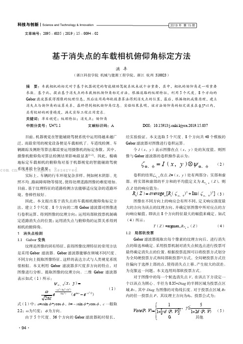
科技与创新┃Science and Technology &Innovation·94·2019年第15期文章编号:2095-6835(2019)15-0094-02基于消失点的车载相机俯仰角标定方法洪丰(浙江科技学院机械与能源工程学院,浙江杭州310023)摘要:车载相机的标定对于基于机器视觉的智能辅助驾驶系统来说十分重要,其中,相机的俯仰角是一项重要参数。
基于此,提出基于消失点的车载相机俯仰角标定方法,根据道路的纹理特征,利用5个尺度、8个方向的Gabor 滤波器获得图像的纹理信息,然后运用局部软投票算法得到消失点的位置,最后,根据相机成像原理,建立消失点与俯仰角的运算关系,最终得到相机俯仰角信息。
实验结果表明,该方法俯仰角的标定误差在0.5°以内,具有较好的测量精度,满足实际工程应用需求。
关键词:单目视觉;纹理特征;消失点;俯仰角中图分类号:U471.1文献标识码:ADOI :10.15913/ki.kjycx.2019.15.037目前,机器视觉在智能辅助驾驶系统中运用得越来越广泛,而最常用的视觉设备便是车载相机了。
车道线检测、车辆跟踪及测距等算法都需要运用摄像机的标定参数,其中,摄像机俯仰角对算法检测结果影响最显著[1-2]。
因此,精确地标定车载相机的俯仰角对基于机器视觉的智能辅助驾驶系统来说十分重要。
实际上,车辆的行车环境复杂多样,例如树木阴影、光照不均、路面障碍物等情况,使得处理道路图像的难度增加。
目前,基于纹理特征的道路检测方法能够适应复杂的道路环境,鲁棒性较好。
因此,本文提出基于消失点的车载相机俯仰角标定方法,建立5个尺度、8个方向的二维Gabor 滤波器对图像进行卷积运算,得到图像的纹理方向;运用局部软投票机制确定道路消失点的位置;运用消失点与俯仰角的运算关系得到相机的俯仰角。
1消失点检测1.1Gabor 变换纹理是图像的固有特征,获得图像纹理特征的常用方法是采用Gabor 滤波器。
- 1、下载文档前请自行甄别文档内容的完整性,平台不提供额外的编辑、内容补充、找答案等附加服务。
- 2、"仅部分预览"的文档,不可在线预览部分如存在完整性等问题,可反馈申请退款(可完整预览的文档不适用该条件!)。
- 3、如文档侵犯您的权益,请联系客服反馈,我们会尽快为您处理(人工客服工作时间:9:00-18:30)。
Simultaneous Vanishing Point Detectionand Camera Calibrationfrom Single ImagesBo Li, Kun Peng, Xianghua Ying, and Hongbin Zha The Key Lab of Machine Perception (Ministry of Education), Peking University, BeijingP.R. ChinaAbstract. For images taken in man-made scenes, vanishing points and focallength of camera play important roles in scene understanding. In this paper, wepresent a novel method to quickly, accurately and simultaneously estimate threeorthogonal vanishing points (TOVPs) and focal length from single images. Ourmethod is based on the following important observations: If we establish a polarcoordinate system on the image plane whose origin is at the image center, anglecoordinates of vanishing points can be robustly estimated by seeking peaks in ahistogram. From the detected angle coordinates, altitudes of a triangle formedby TOVPs are determined. Novel constraints on both vanishing points and focallength could be obtained from the three altitudes. By using the constraints, radi-al coordinates of TOVPs and focal length can be estimated simultaneously. Ourmethod decomposes a 2D Hough parameter space into two cascaded 1D Houghparameter spaces, which makes our method much faster and more robust thanprevious methods without losing accuracy. Enormous experiments on real im-ages have been done to test feasibility and correctness of our method.Keywords: v anishing point detection, calibration using vanishing points, per-ceptual grouping.1 IntroductionUnder a pinhole camera model, a set of parallel lines in 3D space are projected to a set of lines in the image which converge to a common point. This point of intersec-tion, perhaps at infinity, is called the vanishing point. The understanding and interpretation of man-made scene can be significantly simplified by the detection of vanishing points. Its applications [2, 3, 4, 7, 8, 9] range from robotic navigation, camera calibration, 3D reconstruction, augmented reality, image understanding and etc. For instance, for images taken in man-made scenes, without any 3D geome-tric information in Euclidean space, the spatial layouts of the scenes are very difficult to understand. In this case, vanishing points corresponding to three ortho-gonal directions may provide important information. Therefore, the task of detecting the three mutually orthogonal directions of a man-made scene has considerable attraction.G. Bebis et al. (Eds.): ISVC 2010, Part II, LNCS 6454, pp. 151–160, 2010.© Springer-Verlag Berlin Heidelberg 2010152 B. Li et al.1.1 Related WorkPrevious vanishing point detection techniques can be roughly divided into two catego-ries: The first category uses an accumulator cell to accumulate lines passing through the corresponding image point [1, 10, 13]. Peaks in the accumulator space represent the potential vanishing points. The second category does not require seeking the peaks in an accumulator space. Instead, some iterative algorithms, such as the Expectation-maximization algorithm, are used to group lines [9, 12].Here we present some work related to the first category since our method can also be put into this category. Previous methods vary in the choice of accumulator space. For example, Barnard [1] suggested the unbounded image space can be mapped into the bounded surface of a Gaussian sphere. Tuytelaars et al. [13] mapped points into different bounded subspaces according to their coordinates. Rother [10] pointed out that these methods could not preserve the original distances between lines and points. In his method, the intersections of all pairs of non-collinear lines are considered as accumulator cells instead of a parameter space. But since these accumulator cells are difficult to index, searching for the maximal from the accumulator cells is slow.A common problem among previous methods [1, 13] is that they do not consider constraints between vanishing points and focal length. For images of man-made scene, there are constraints between TOVPs and focal length. In general, coordinates of two orthogonal vanishing points are enough to calculate focal length using these constraints. If the third vanishing point is detected, it could be used to refine the re-sult. Without considering the constraints in detection, sometimes the detected vanish-ing points may be incorrect and focal length cannot be calculated. In order to solve this problem, Van Den Heuvel [6] used the constraints as additional criterion in detec-tion. But this method is based on the assumption that the camera is calibrated. Rother [10] also used the constraints in searching for the vanishing points. But due to the reason mentioned above, this approach requires more computational efforts.In this paper, we present novel constraints developed from the previous constraints mentioned above. Our method firstly detects altitudes of the triangle formed by TOVPs. The triangle is called the TOVPs triangle in this paper. The novel constraints on both vanishing points and focal length are obtained from the three altitudes. Based on the constraints, the 2D accumulator space could be simplified into two cascaded 1D accumulator spaces. Vanishing point detection by our method is much faster than previous methods. Focal length and vanishing points could be estimated simulta-neously and the previous constraints are still guaranteed.2 Notations and Basic Principles2.1 Pinhole Camera ModelConsider a point in 3D world x,y,z,1 . u,v,1 is its image point. In the pinhole camera model, the two homogeneous coordinates satisfy:µ (1)Simultaneous Vanishing Point Detection and Camera Calibration 153 where µis a scale factor. is the intrinsic matrix defined as:f s u0αf v001(2)where f is the focal length of camera. α is the aspect ratio. (u ,v ) represents the principle point of the camera. s is the skew parameter. is the extrinsic matrix, determined by the position and orientation of the camera. Further information about pinhole camera model can be found in [5].In this paper, we assume the skew parameter to be zero, the aspect ratio to be one, and the principal point to be centered. The only intrinsic parameter that we con-sider is the focal length f.2.2 Relationship between TOVPs and Focal LengthLet x,y,z be an orthogonal system of coordinates associated with a viewing camera, such that the origin of the system coincides with the optical center and the z-axis with the optical axis. The image plane is defined by the equation z f where f is the focal length. Let (x ,y ), (x ,y ), (x ,y ) be coordinates of the TOVPs v ,v ,v in an image of the man-made architectural environment. One important property of the TOVPs is that for triangle v v v , its orthocenter coincides with the principal point of the image, which is assumed to be the image center in this paper. Relationship be-tween vanishing points and focal length can be presented as:x x y y f 0x x y y f 0x x y y f 0(3) Detailed explanations for these properties could be found in [2].3 Distribution of Intersections of All Pairs of Converging LinesDue to errors in line detection [11], real intersections of converging lines correspond-ing to one vanishing point are distributed around the true vanishing point. We discov-ered that if these intersections are not too close to the image center, their distribution has very different variances in different directions. This distribution could be approx-imately interpreted as an elliptical Gaussian distribution. Its minor axis is very short with respect to major axis. Meanwhile, the included angle between the major axis and a line determined by the true vanishing point and the image center is very small. Fig-ure 1a shows an image with line segments converging to TOVPs. Lines corresponding to different vanishing points are shown in different colors. We add noises to these lines so that their intersections do not coincide with the vanishing points. Blue crosses represent intersections of all pairs of detected lines. As shown in Figure 1a, distribu-tions of the blue crosses are approximately elliptical Gaussian distributions around vanishing points respectively.154 B. Li et al.(a) (b)Fig. 1. (a) An image of converging lines with noise added. The TOVPs v ,v ,v form a triangle called the TOVPs triangle. Lines corresponding to different vanishing points are shown in different colors. Blue crosses represent intersections of all pairs of detected lines. Orthocen-ter of the TOVPs triangle coincides with the image center. Altitudes of the TOVPs triangle are shown as blue solid lines. (b) Histogram of angle coordinates of intersections in (a).Consider distribution of intersections of converging lines corresponding to one va-nishing point in a polar coordinate system with origin at the image center. The major axis of the elliptical Gaussian distribution approximately passes through the origin. Angle coordinates of true vanishing points could be obtained by seeking peaks in histogram of angle coordinates of intersections. Figure 1b shows the histogram of angle coordinates of intersections of all pairs of lines in Figure 1a. Three significant peaks correspond to angle coordinates of the three vanishing points in Figure 1a.As discussed in Section 2.2, orthocenter of the TOVPs triangle coincides with the image center, which is considered as origin of the polar coordinate system. Therefore, if angle coordinates of the TOVPs are detected, altitudes of the TOVPs triangle could be obtained. In our method, we detect altitudes of the triangle firstly. Then constraints from these altitudes are used to detect radial coordinates of the TOVPs and focal length simultaneously (described in Section 4). The detected altitudes of the triangle are shown as blue solid lines in Figure 1a.4 Approach4.1 Detecting Altitudes of the TOVPs TriangleLet the image center be the origin of a Cartesian coordinate system in the image plane. The Cartesian coordinates of the three vanishing points v ,v ,v are denoted by (x ,y ), (x ,y ), (x ,y ), respectively. The polar coordinates of v ,v ,v is denoted by (θ ,ρ ), (θ ,ρ ), (θ ,ρ ), respectively. Polar transformation of theCartesian coordinates (x,y)is defined as:θ tan yρ x y (4)θSimultaneous Vanishing Point Detection and Camera Calibration 155 According to Section 3, angle coordinates of the TOVPs could be detected by seeking peaks in θ-histogram of intersections of all pairs of detected lines. Consider an alti-tude of the TOVPs triangle v v v , which passes through vertex v . The altitude also passes through the image center, which is defined as origin in the polar coordinate system. Given angle coordinates θ ,θ ,θ of the three vanishing points, the altitudes are also determined. It can be represented as:x sin θ y cos θ 0,i 1,2,3 (5)In Figure 2a, intersections of all pairs of detected lines are represented by blue crosses. Figure 2b shows the θ-histogram of the intersections in Figure 2a. The three peaks correspond to the TOVPs. The detected altitudes are shown in Figure 2a.Fig. 2. (a) A polar coordinate system whose origin is at the image center. Intersections of all pairs of detected lines are marked by blue crosses. Detected altitudes of the TOVPs triangle are shown as solid black lines. (b) θ-histogram of the intersections. (c) A series of TOVPs triangles corresponding to different potential TOVPs and focal length. Detected TOVPs are marked by black squares.4.2 Constraints from Three Altitudes of the TOVPs TriangleConsider coordinates of the TOVPs (x ,y ), (x ,y ), (x ,y ) and focal length f as seven unknowns. Since the TOVPs lie on the three detected altitudes respectively, we have the following equations from (5).x sin θ y sin θ 0,i 1,2,3 (6)(a)(b)(c)T156 B. Li et al.Constraints provided by the detected altitudes of the TOVPs triangle v v v could be represented as an equation system formed by (3) and (6). By solving the equation system, radial coordinates of the TOVPs could be denoted as:ρ x y η f, (7) where i 1,2,3 andηcos(θ θ )( )( )ηcos(θ θ )cos(θ θ )cos(θ θ )(8)ηcos(θ θ )Then we obtain:x ρ cosθy ρ sinθ (9) where i 1,2,3. According to (7) and (9), for different f, the corresponding TOVPs triangles are similar triangles, as shown in Figure 2c.4.3 Simultaneously Detecting Radial Coordinates of the TOVPs and FocalLengthThe intersections of all pairs of detected lines can be divided into three sets according to the nearest altitudes. Since altitudes have already been detected in Section 4.1 as shown in Figure 2a, we project intersections on the corresponding altitudes and use the projections as candidates for the TOVPs. In Figure 2c, projections of intersections are marked by blue crosses. These projections are divided into three sets S ,i 1,2,3 according to corresponding altitudes. Consider the distribution of radial coordinates ρof points in S . Define g (ρ),i 1,2,3as the distribution function. Radial coordinate ρ of the i-th vanishing point should be the value that maximizes g (ρ). Using (7), we can present this distribution function as a function of f:g (ρ) g (η f) (10) Focal length should be chosen to maximize three g (η f),i 1,2,3 simultaneously. We define h(f)as a weighted sum of the three distributions:h(f) w g (η f) w g (η f) w g (η f) (11) where w ,i 1,2,3, is the weight of g . f should be a solution of:f arg max(h(f)) (12)Simultaneous Vanishing Point Detection and Camera Calibration 157Since f is measured by pixel and within a bounded range, this equation can be solved by simply enumerating all possible values of f. Given the estimation of f, coordinates of the TOVPs can be calculated by (7) and (9).Computational complexity of our approach is determined by the following:(a)The number of intersections. In an image with n detected lines, the numberof intersections could be O(n ),(b)The number of accumulator cells used to detect angle coordinates θ of thevanishing points, denoted by N .(c)The number of accumulator cells used to detect focal length f and radialcoordinates ρof the vanishing points, denoted by N .Generally N and N are no more than 3000. The complexity of this approach can be O(n N N ).5 ExperimentsMany experiments have been done to test validity and correctness of our method. In our tests we use 640 480images and the image center is considered as the origin of the image space. Accumulator space 0,2π of θ is discretized into 600 accumu-lator cells. The range of f is set to 500,3200 and also discretized into accumulator cells. Weights used in (11) are all set to 1. Since flexibility of our method relies on the constraints provided by the TOVPs, images we use all contain three significant vanishing points.In first experiment, images taken with different focal lengths are used to test our method. Figure 3.a-c show three images of same object with f f f . For im-ages taken with longer focal length, detected lines are much closer to parallel. Many previous methods fail to obtain a reliable focal length when true focal length is relatively long because the vanishing points are close to infinity and difficult to estimate. In our method, novel constraints are used as additional criterion to reduce error. Detected coordinates of vanishing points and focal lengths of Figure 3a-c are shown in Table 1. The vanishing points are not marked in the figures because some of them are too far from image. Focal length errors in the three cases are all below 10%, compared with values calculated by method proposed in [14].(a) (b) (c)Fig. 3. Images taken with different focal lengths. We have .158 B. Li et al.Table 1. Focal length and vanishing point coordinates of Figure 3a-c estimated by our methodImage f TOVPs Fig 3.a713 (-949,-649), (1009,-693), (17,758) Fig 3.b1319 (1728,-1186), (-1767,1108), (34,1516) Fig 3.c 1880 (2325,1463), (82,2546), (-2345,-1312)Table 2. Focal length and vanishing point coordinates of Figure 4a-d estimated by our methodImage f TOVPs Fig 4.a713 (28,-1437), (897,443), (-883,408) Fig 4.b772 (1166,567), (750,489), (-47,-1146) Fig 4.c695 (-891,-366), (631,-217), (-169,1731) Fig 4.d 721 (882,530), (-1033,-738), (-90,831)In second experiment, we test our method by using images of different scenes. Figure 4a and 4b are taken by us. Figure 4c and 4d are from the ZuBuD 1 database. Intersections of detected lines in the images are marked by blue crosses. Detected vanishing points are marked by black squares. Detected coordinates of TOVPs and focal lengths are shown in Table 2.We also compared our method with that using EM algorithm [9], which is considered as a quite efficient one among previous methods. Both methods are imple-mented in MATLAB M-files. They use same line detection algorithm and here we only compare the time cost by vanishing point detection. The results of vanishing point detection using the two methods are comparable. But our method costs much less time. Minimal, average and maximal computational time are reported in Figure 5. Computational time cost by our method in most cases is no more than 0.1 second. Our method can be used in real-time applications.Fig. 4. Comparison of computation time 1 http://www.vision.ee.ethz.ch/showroom/zubudC o m p u t i t i o n t i m e (s e c .)Simultaneous Vanishing Point Detection and Camera Calibration 159(a) (b)(c) (d)Fig. 4. Experiments on images of both indoor and outdoor scenes. (a) and (b) are taken by us.(c) and (d) are from the ZuBuD database. Intersections of detected lines in the images are marked by blue crosses. Detected vanishing points are marked by black squares.5 ConclusionsA novel method for simultaneous vanishing point detection and camera calibration is proposed in this paper. The method can be described in two steps: Firstly, angle coor-dinates of the three vanishing points are detected. Secondly, focal length and radial coordinates of the vanishing points are estimated simultaneously.This method is based on an observation that angle coordinates of vanishing points can be estimated easily and robustly. Altitudes of the TOVPs triangle may be deter-mined from the detected angle coordinates of the TOVPs. The three altitudes provide constraints on both vanishing points and focal length, which largely simplifies the160 B. Li et al.estimation problem of vanishing points and focal length. Compared to previous me-thods, our method requires much less time and memory.AcknowledgementThis work was supported in part by the NSFC Grant (No.61075034), the NHTRDP 863 Grant No. 2009AA01Z329, and the NHTRDP 863 Grant No.2009AA012105. References1.Barnard, S.T.: Interpreting perspective images. Artificial Intelligence 21, 435–462 (1983)2.Caprile, B., Torre, V.: Using vanishing points for camera calibration. International Jour-nal of Computer Vision 4, 127–140 (1990)3.Cipolla, R., Drummond, T., Robertson, D.: Camera calibration from vanishing points inimages of architectural scenes. In: Proc. British Machine Vision Conference, vol. 2, pp.382–392 (1999)4.Van Gool, L., Zeng, G., Van Den Borre, F., Müller, P.: Towards mass-produced buildingmodels. In: Photogrammetric Image Analysis, PIA (2007)5.Hartley, R., Zisserman, A.: Multiple view geometry in computer vision. Cambridge Uni-versity Press, Cambridge (2003)6.Van Den Heuvel, F.A.: Vanishing point detection for architectural photogrammetry. In-ternational Archives of Photogrammetry and Remote Sensing 32(Part 5), 652–659 (1998) 7.Hedau, V., Hoiem, D., Forsyth, D.: Recovering the spatial layout of cluttered rooms. In:Proc. International Conference on Computer Vision (2009)8.Kong, H., Audibert, J., Ponce, J.: Vanishing point detection for road detection. In: Proc.IEEE Conf. Computer Vision and Pattern Recognition, pp. 96–103 (2009)9.Košecká, J., Zhang, W.: Video compass. In: Heyden, A., Sparr, G., Nielsen, M., Johan-sen, P. (eds.) ECCV 2002. LNCS, vol. 2353, pp. 657–673. Springer, Heidelberg (2002) 10.Rother, C.: A new approach for vanishing point detection in architectural environments.Image and Vision Computing 20, 647–655 (2002)11.Shufelt, J.A.: Performance evaluation and analysis of vanishing point detection Tech-niques. IEEE Trans. Pattern Analysis and Machine Intelligence 21(3), 282–288 (1999) 12.Tardif, J.: Non-iterative approach for fast and accurate vanishing point detection. In:Proc. International Conference on Computer Vision (2009)13.Tuytelaars, T., Van Gool, L., Proesmans, M., Moons, T.: The cascaded Hough transformas an aid in aerial image interpretation. In: Proc. International Conference on Computer Vision, pp. 67–72 (1998)14.Zhang, Z.: Flexible camera calibration by viewing a plane from unknown orientations. In:Proc. International Conference on Computer Vision (1999)。
