瑞萨科技 (Renesas Technology) - 电机控制算法
2SC4331中文资料(renesas)中文数据手册「EasyDatasheet - 矽搜」

芯片中文手册,看全文,戳
为我们客户,
旧公司名称产品目录等资料
接手两者所有业务
因此,尽管旧公司名称防护留这个文件中,它是一个有效 电子文档.我们感谢您理解.
3. 7.5厘米 × 0.7毫米,陶瓷电路板装
封装图(单位: mm)
6.5 ±0.2 5.0 ±0.2 1.5
4
2.3 ±0.2 0.5 ±0.1
1.6 ±0.2 1
2
3
5.5 ±0.2
1.1 ±0.2
13.7最小. 7.0最低
0.5
0.5
2.3 2.3
0.75
TO-251 (MP-3)
6.5 ±0.2 5.0 ±0.2 4.4 ±0.2
8. 你应该使用由瑞萨电子所指定范围内本文档中描述瑞萨电子产品,特别是相对于所述最大额定值,操作电源电压范围,移 动电源电压范围,热辐射特性,安装和其它产品特性.瑞萨电子有权对因使用瑞萨电子产品除这些特定范围故障或损坏 不承担任何责任.
9. 本公司一直致力于提高产品质量和可靠性,半导体产品有 具体特点,如故障以一定速率和故障某些使用条件下发生.进一步, 瑞萨电子产品不受辐射性设计.请一定要采取安全措施,以
芯片中文手册,看全文,戳
注意
1. 本文档中所有信息为发出这份文件日期.这样信息,但是,如有更改恕不另行通知.购买或使用本文中列出任何瑞萨电 子产品前,请确认与瑞萨电子营业部最新产品信息.另外,请大家定期和仔细额外和不同信息由瑞萨电子披露,例如,通 过我们网站披露.
BLDC电机控制算法(瑞萨)

无刷电机属于自換流型(自我方向轉換),因此控制起来更加复杂。
BLDC电机控制要求了解电机进行整流转向的转子位置和机制。
对于闭环速度控制,有两个附加要求,即对于转子速度/或电机电流以及PWM信号进行测量,以控制电机速度功率。
BLDC电机可以根据应用要求采用边排列或中心排列PWM信号。
大多数应用仅要求速度变化操作,将采用6个独立的边排列PWM信号。
这就提供了最高的分辨率。
如果应用要求服务器定位、能耗制动或动力倒转,推荐使用补充的中心排列PWM信号。
为了感应转子位置,BLD C电机采用霍尔效应传感器来提供绝对定位感应。
这就导致了更多线的使用和更高的成本。
无传感器BLDC控制省去了对于霍尔传感器的需要,而是采用电机的反电动势(电动势)来预测转子位置。
无传感器控制对于像风扇和泵这样的低成本变速应用至关重要。
在采有BLDC电机时,冰箱和空调压缩机也需要无传感器控制。
空载时间的插入和补充大多数BLDC电机不需要互补的PWM、空载时间插入或空载时间补偿。
可能会要求这些特性的BLDC 应用仅为高性能BLDC伺服电动机、正弦波激励式BLDC电机、无刷AC、或PC同步电机。
控制算法许多不同的控制算法都被用以提供对于BLDC电机的控制。
典型地,将功率晶体管用作线性稳压器来控制电机电压。
当驱动高功率电机时,这种方法并不实用。
高功率电机必须采用PWM控制,并要求一个微控制器来提供起动和控制功能。
控制算法必须提供下列三项功能:•用于控制电机速度的PWM电压•用于对电机进整流换向的机制•利用反电动势或霍尔传感器来预测转子位置的方法脉冲宽度调制仅用于将可变电压应用到电机绕组。
有效电压与PWM占空度成正比。
当得到适当的整流换向时,BLDC的扭矩速度特性与一下直流电机相同。
可以用可变电压来控制电机的速度和可变转矩。
功率晶体管的换向实现了定子中的适当绕组,可根据转子位置生成最佳的转矩。
在一个BLDC电机中,MCU必须知道转子的位置并能够在恰当的时间进行整流换向。
2SK1522中文资料(renesas)中文数据手册「EasyDatasheet - 矽搜」

7.如果这些产品或技术受日本出口管理限制,必须是 日本政府根据许可证出口,不能导入比批准目地以外国家.
禁止任何转移或再出口违反出口管制法律和日本及/或目地国家相关规定.
8.请与瑞萨科技公司对这些材料或产品进一步详情 其中所载.
芯片中文手册,看全文,戳
V GS = ±25 V, V DS = 0 V DS = 360 V, V GS = 0 V DS = 400 V, V GS = 0 ID =1毫安,V DS = 10 V ID = 25 A, V GS = 10 V * 1
ID = 25 A, V DS = 10 V * 1 VDS = 10 V, V GS = 0, F = 1兆赫
芯片中文手册,看全文,戳
2SK1521, 2SK1522
绝对最大额定值
(Ta = 25°C)
项目
漏极至源极电压
2SK1521
2SK1522
门源电压
漏极电流
漏电流峰值
身体流失二极管反向漏电流
频道耗散
通道温度
储存温度
注:1.PW
10 µs, 占空比
1%
2.价值在T C = 25°C
符号
ID = 25 A, V GS = 10 V, RL = 1.2
IF = 50 A, V GS = 0
IF = 50 A, V GS = 0, di F/ DT = 100 A /μs的
3
—
远期转移导纳
|yfs|
22
输入电容
Ciss —
输出电容
Coss —
反向传输电容
Crss —
导通延迟时间 上升时间 关断延迟时间 下降时间 身体向前漏二极管 电压
瑞萨科技-RENESAS公司产品导购手册

瑞萨科技-RENESAS(RENESAS)于2003年4月1日—由日立制作所半导体部门和三菱电机半导体部门合并成立。
RENESAS结合了日立与三菱在半导体领域方面的先进技术和丰富经验,是无线网络、汽车、消费与工业市场设计制造嵌入式半导体的全球领先供应商。
瑞萨科技是世界十大半导体芯片供应商之一,在很多诸如移动通信、汽车电子和PC/AV 等领域获得了全球最高市场份额。
瑞萨集成电路设计(北京)有限公司苏州分公司(RDB-SU)是瑞萨科技全资子公司,2004年1月成立以来,现已拥有150多名优秀工程师,承担着家电和汽车电子领域MCU的一系列设计工作,并在2006年4月开始开发面向中国市场的MCU。
瑞萨科技在2003年4月1日正式成立,以领先的科技实现人类的梦想。
结合了日立与三菱电机在半导体领域上的丰富经验和专业知识,配合全球二万七千名员工的无限创意,我们将无处不在,超乎你的想像。
科技的价值在于让一切变得可能,身为一家具有领导性和值得信赖的智能晶片解决方案供应商,我们对于拓展明日无处不在的网络世界,担当重要的角色。
我们的创造力具前瞻性,为人类创造出更舒适美好的生活。
公司相关产品•H8系列单片机•M16C系列单片机•R8C系列单片机•32位SuperH系列单片机H8系列单片机H8单片机是日立生产的日本使用最广泛的单片机之一,它具有高速、低耗、大容量等优点。
H8系列单片机最新报价产品型号产品描述价格($) HD64F3334YFLH16 IC H8 MCU FLASH 32K 80QFP 12.316HD64F3337SF16 IC H8 MCU FLASH 60K 80QFP 14.321HD64F3337YFLH16 IC H8 MCU FLASH 60K 80QFP 12.34HD64F3334YFLH16V MCU 3/5V 32K PB-FREE 80-QFP 11.799HD6473294F16V MCU 3/5V 32KB 64-QFP 12.886HD64F3337SF16V MCU 3/5V 60K PB-FREE 80-QFP 15.912D64F3337YFLH16V MCU 5V 60K PB-FREE 80-QFP 14.28HD64F3437STF16V MCU 3/5V 60K PB-FREE 100-TQFP 18.106HD64F3337YCP16 IC H8 MCU FLASH 60K 84PLCC 16.197HD64F3437TFLH16V IC H8/3437 MCU FLASH 60K 100TQFP 18.801HD64F3337YCP16V MCU 3/5V 60K PB-FREE 84-PLCC 21.197D64F3437TFLH16V MCU 5V 60K PB-FREE 100-TQFP 23.155DF36912GFHV IC H8 MCU FLASH 8K 32LQFP 4.178H8/3008 MCU ROMLESS 100QFP 4.275D13008VFBL25V ICHD6413008FBL25V IC H8 MCU ROMLESS 100-QFP 4.083DF36077GHV IC H8 MCU FLASH 56K 64QFP 6.099DF36012GFYV IC H8/TINY MCU FLASH 48LQFP 7.236DF36014FXV IC H8/TINY MCU FLASH 48LQFP 7.344DF36012GFXV IC H8/TINY MCU FLASH 48LQFP 7.776DF36014FPV IC H8 MCU FLASH 32K 64LQFP 7.128DF36014GFXV IC H8/TINY MCU FLASH 48LQFP 7.77DF36014GFPV IC H8 MCU FLASH 32K 64LQFP 8.103DF38102HV IC H8/SLP MCU FLASH 64QFP 6.244HD64F3684GHV IC H8/TINY MCU FLASH 64QFP 6.149HD64F3684GFPV IC H8 MCU FLASH 32K 64LQFP 8.273D12312SVTE25V IC H8S MPU ROMLESS 100TQFP 7.945DF38004H4V IC H8/SLP MCU FLASH 64QFP 6.521DF38004FP4V IC H8/SLP MCU FLASH 64LQFP 6.978MPU ROMLESS 128QFP 6.972D12322RVF25V ICH8SHD64F3687GFPV IC H8 MCU FLASH 56K 64LQFP 8.211DF38104HV IC H8 MCU FLASH 32K 64QFP 7.976HD64F3664FPV IC H8/3664 MCU FLASH 32K 64LQFP 8.672D12392F20V IC H8S/2300 MCU ROMLESS 128QFP 7.603 D12390F20V IC H8S MPU ROMLESS 128QFP 8.16D12321VF25V IC H8S/2300 MCU ROMLESS 128QFP 8.16 HD64F3694GFYV IC H8 MCU FLASH 32K 48QFP 7.973 HD64F3694GFTV IC H8/TINY MCU FLASH 48QFN 7.61 DF36079GHV IC H8/36079 MCU FLASH 64-QFP 8.591 DF38002H10V IC H8/SLP MCU FLASH 64QFP 8.138 DF38002H4V IC H8/38002 MCU FLASH 64QFP 7.891 HD64F3684FPV IC H8 MCU FLASH 32K 64LQFP 8.542 DF2317VTEBL25V IC H8S MCU FLASH 128K 100TQFP 8.611 DF38004FP10WV IC H8/SLP MCU FLASH 64LQFP 7.925 DF38004H10WV IC H8/SLP MCU FLASH 64QFP 8.303 HD64F38024RHV IC H8/SLP MCU FLASH 80QFP 8.07 HD64F38024RWV IC H8/SLP MCU FLASH 80TQFP 8.953 DF38104HWV IC H8/SLP MCU FLASH 64QFP 8.262 HD64F3644HV IC H8/3644 MCU FLASH 32K 64QFP 9.797 HD64F38024RDV IC H8/SLP MCU FLASH 80QFP 9.022 HD64F3644DV IC H8/3644 MCU FLASH 64QFP 10.534 DF38076RH4V IC H8 MCU FLASH 52K 80QFP 8.826 HD64F38024DV IC H8/SLP MCU FLASH 80QFP 8.741 DF38076RH10V IC H8/SLP MCU FLASH 80QFP 10.98 DF38076RW10V IC H8/SLP MCU FLASH 80TQFP 9.608 DF38076RLP4V IC H8 MCU FLASH 52K 85TFLGA 10.419 DF38076RLP10V IC H8/SLP MCU FLASH 85TFLGA 10.439 DF38086RH4V IC H8 MCU FLASH 52K 80QFP 11.704 DF38086RW4V IC H8/SLP MCU FLASH 80TQFP 12.206 DF38076RH10WV IC H8/SLP MCU FLASH 80QFP 12.257 DF38076RW10WV IC H8/SLP MCU FLASH 80TQFP 12.089 DF38086RW10V IC H8/SLP MCU FLASH 80TQFP 10.206 DF38086RH10V IC H8/SLP MCU FLASH 80QFP 12.587MPU ROMLESS 144LQFP 12.144H8SD12674RVFQ33V ICDF2117VBG20V IC H8S/2117 MCU FLASH 176LFBGA 12.886 DF2117VLP20V IC H8S/2117 MCU FLASH 145TFLGA 11.071 DF38086RLP10V IC H8/SLP MCU FLASH 85TFLGA 12.281H8S/2300 MCU ROMLESS 144LQFP 10.903 D12373RVFQ33V ICDF38086RH10WV IC H8/SLP MCU FLASH 80QFP 13.478 DF38086RW10WV IC H8/SLP MCU FLASH 80TQFP 13.853 DF2218UTF24V IC H8S MCU FLASH 128K 100TQFP 10.406 DF2218TF24V IC H8S MCU FLASH 128K 100TQFP 11.92 DF2140BVTE10V IC H8S/2100 MCU FLASH 100TQFP 12.911 DF3064BF25V IC H8/3064B MCU FLASH 100QFP 13.873 DF2134AFA20V IC H8S/2100 MCU FLASH 80QFP 11.474 DF38086RLP10WV IC H8/SLP MCU FLASH 85TFLGA 14.926DF2215RUTE24V IC H8S/2215R MCU FLASH 120TQFP 13.156 DF2238RFA6V IC H8S MCU FLASH 256K 100QFP 13.464 DF2238RFA13V IC H8S MCU FLASH 256K 100QFP 14.28 DF2160BVT10V IC H8S/2100 MCU FLASH 144TQFP 14.498 DF2215RUBR24V IC H8S/2215R MCU FLASH 112-LFBGA 11.297 DF2318VTE25V IC H8S MCU FLASH 256K 100TQFP 13.517 DF2145BVTE10V IC H8S MCU FLASH 256K 100TQFP 14.784 DF2317VTE25V IC H8S MCU FLASH 128K 100TQFP 14.012 DF2612FA20V IC H8S MCU FLASH 128K 80QFP 11.737 DF3026XBL25V IC H8 MCU FLASH 256K 100TQFP 12.87 D13003TF16V IC H8/3003 ROMLESS 112QFP 15.885 DF2328VF25V IC H8S MCU FLASH 256K 128QFP 13.541 DF3069RF25V IC H8 MCU FLASH 128K 100QFP 13.039 DF2328BVTE25V IC H8S MCU FLASH 256K 120TQFP 14.731 DF2398TE20V IC H8S MCU FLASH 256K 120TQFP 16.517 DF2238RBR13V IC H8S MCU FLASH 256K 112BGA 16.644 DF61653N50FTV IC H8SX MCU FLASH 384K 120TQFP 14.63 DF2377RVFQ33V IC H8S MCU FLASH 384K 144LQFP 14.555 DF2239FA20V IC H8S MCU FLASH 384K 100QFP 13.44 DF2328VTE25V IC H8S MCU FLASH 256K 120TQFP 15.691 DF61654N50FTV IC H8SX/1654 MCU FLASH 120TQFP 17.098 DF2338VFC25V IC H8S/2300 MCU FLASH 144QFP 16.67 DF2377RVFQ33WV IC H8S MCU FLASH 384K 144LQFP 17.291 DF2345TE20V IC H8S/2345 MCU FLASH 100TQFP 16.09 DF2215TE16V IC H8S MCU FLASH 256K 120TQFP 16.218 R5F61668RN50FPV IC H8SX/1668 MCU FLASH 144LQFP 14.392 DF2329BVTE25V IC H8S MCU FLASH 384K 120TQFP 16.07 DF2239BQ16V IC H8S/2239 MCU FLASH 112BGA 19.536 DF3067RF20V IC H8/3067 MCU FLASH 128K 100QFP 16.988 DF2319VF25V IC H8S MCU FLASH 512K 100QFP 17.715 DF2215BR16V IC H8S/2200 MCU FLASH 112LFBGA 16.52 DF2319VTE25V IC H8S MCU FLASH 512K 100TQFP 18.125 DF2636UF20V IC H8S/2600 MCU FLASH 128QFP 18.27 DF2633TE16V IC H8S/2600 MCU FLASH 120TQFP 20.948 DF2166VT33V IC H8S MCU FLASH 512K 144TQFP 19.8 DF2329VF25V IC H8S MCU FLASH 384K 128QFP 21.066 DF2167VT33 IC H8S MCU FLASH 384K 144-TQFP 21.657 DF2339EVFC25V IC H8S/2300 MCU FLASH 144QFP 23.312 DF2339VFC25V IC H8S/2300 MCU FLASH 144QFP 21.808 DF2329EVTE25V IC H8S MCU FLASH 384K 120TQFP 24.564 DF2630F20V IC H8S/2600 MCU FLASH 128QFP 25.445 DF2630WF20V IC H8S/2600 MCU FLASH 128QFP 31.317 DF36912GTPAFV IC H8/36912 MCU FLASH 32SOP 4.368HD64F3672FXV IC H8/3672 MCU FLASH 48LQFP 4.115 HD64F3670FYV IC H8/3670 MCU FLASH 48LQFP 4.522 DF3024FBL25V IC H8 MCU FLASH 128K 100QFP 6.687 DF3062BFBL25V IC H8 MCU FLASH 128K 100QFP 7.385 DF36012GFPV IC H8 MCU FLASH 16K 64LQFP 7.344 HD64F36012GFP IC H8 MCU FLASH 16K 64-LQFP 6.588 D13008VF25V IC H8S MPU ROMLESS 100QFP 6.71 DF36024FPV IC H8/36024 MCU FLASH 64LQFP 7.104 DF36024FXV IC H8 MCU FLASH 32K 48LQFP 6.438 DF36014FPWV IC H8/36014 MCU FLASH 32K 64LQFP 6.911 DF38004H10V IC H8 MCU FLASH 32K 64QFP 8.466 DF36087FPV IC H8 MCU FLASH 56K 64LQFP 7.779 DF38104FPV IC H8 MCU FLASH 32K 64LQFP 7.624 HD64F3687GHV IC H8/TINY MCU FLASH 64QFP 8.328 HD64F3694FPV IC H8 MCU FLASH 32K 64LQFP 8.68 HD64F3694HV IC H8 MCU FLASH 32K 64QFP 8.094 HD64F3694FXV IC H8 MCU FLASH 32K 48LQFP 6.803 D13008F25V IC H8S MPU ROMLESS 100QFP 7.841 HD64F3694GFXV IC H8 MCU FLASH 32K 48LQFP 7.248 HD64F3694GHV IC H8/TINY MCU FLASH 64QFP 7.61 HD64F3694GFPV IC H8 MCU FLASH 32K 64LQFP 8.577 DF36079LFZV IC H8/36079 MCU FLASH 64LQFP 8.349 DF36079GFZV IC H8/36079 MCU FLASH 64-LQFP 6.655 DF36014FPJV IC H8/36014 MCU FLASH 32K 64LQFP 6.877 HD64F3684HV IC H8 MCU FLASH 32K 64QFP 8.666 DF38104FPWV IC H8/SLP MCU FLASH 64LQFP 8.65 DN3687GFPV IC H8/3687 MCU EEPROM 64LQFP 8.797 DF2327BVFBL25V IC H8S/2300 MCU FLASH 128QFP 9.358 HD64F38024RWIV IC H8/SLP MCU FLASH 80TQFP 8.189 D12324SVF25V IC H8S MPU ROMLESS 128QFP 9.583 DF38076RW4V IC H8/SLP MCU FLASH 80TQFP 9.275 DF2211FP24V IC H8S MCU FLASH 64K 64LQFP 10.612 DF2211UFP24V IC H8S MCU FLASH 64K 64LQFP 9.228 D13002F16V IC H8/3002 ROMLESS 100QFP 10.345 D12332VFC25V IC H8S MPU ROMLESS 144QFP 10.479 DF38344HWV IC H8/38344 MCU FLASH 32K 100QFP 10.807 HD64F2212UFP24 IC H8S MCU FLASH 128K 64-LQFP 11.206 R4F2462VFQ34V IC H8S/2462 MCU FLASH 144LQFP 9.867 HD64F3644PV IC H8/3644 MCU FLASH 32K 64SDIP 10.514 DF38086RLP4V IC H8 MCU FLASH 52K 85TFLGA 11.185 DF3048BF25V IC H8/3048B MCU FLASH 100QFP 10.164 DF3048BVF25V IC H8 MCU FLASH 128K 100QFP 12.16 DF2148BFA20V IC H8S/2148B MCU FLASH 100QFP 11.88DF2134AVTF10V IC H8S/2134 MCU FLASH 80TQFP 13.841 DF2134ATF20V IC H8S/2134 MCU FLASH 80TQFP 12.036 DF2215RTE24V IC H8S/2215R MCU FLASH 120TQFP 14.978 DF2318VF25V IC H8S/2300 MCU FLASH 100QFP 13.056 DF2145BFA20V IC H8S/2145B MCU FLASH 100QFP 11.424 DF2214BQ16V IC H8S/2214 MCU FLASH 112-TFBGA 15.096 DF2145BVFA10V IC H8S/2145B MCU FLASH 100QFP 11.22 DF2378BVFQ35V IC H8S/2378 MCU FLASH 144-LQFP 14.803 DF2138ATF20V IC H8S/2138 MCU FLASH 80TQFP 11.44 DF2138AVTF10V IC H8S/2138 MCU FLASH 80TQFP 12.48 DF2266TF20V IC H8S/2266 MCU FLASH 100TQFP 11.856 DF2266TF13V IC H8S/2266 MCU FLASH 100-TQFP 14.56 DF38099FP10WV IC H8/38099 MCU FLASH 100LQFP 14.811 DF2238RTE6V IC H8S/2200 MCU FLASH 100TQFP 12.883 DF2238RTF6V IC H8S/2200 MCU FLASH 100TQFP 14.995 DF2238RTF13V IC H8S MCU FLASH 256K 100TQFP 13.306 DF2628FA24V IC H8S/2628 MCU FLASH 100QFP 13.871 DF2144AVTE10V IC H8S/2144 MCU FLASH 100TQFP 15.792 DF2368VTE34V IC H8S/2368 MCU FLASH 120TQFP 11.82 DF2378AVFQ34V IC H8S/2300 MCU FLASH 144LQFP 15.768 DF2161BVT10V IC H8S/2100 MCU FLASH 144TQFP 12.744 DF2328BVF25V IC H8S MCU FLASH 256K 128QFP 12.744 DF2398F20V IC H8S/2300 MCU FLASH 128QFP 13.608 DF2437FV IC H8S/2437 MCU FLASH 128QFP 13.608 HD6473726FV MCU 8BIT 48K OTP 80-QFP 16.058 DF3029F25V IC H8 MCU FLASH 512K 100QFP 12.155 DF3028X25V IC H8/3028 MCU FLASH 100TQFP 14.914 DF2372VLP34V IC H8S/2372 MCU FLASH 145-LGA 12.734 DF2367VF33V IC H8S/2367 MCU FLASH 128QFP 16.286 DF2378BVFQ35WV IC H8S/2378 MCU FLASH 144-QFP 16.739 DF2268FA20V IC H8S/2268 MCU FLASH 100QFP 12.463 DF3069RX25V IC H8/3069R MCU FLASH 100TQFP 12.939 DF2238RBQ13V IC H8S/2238R MCU FLASH 112TFBGA 15.276 DF2238RBQ6V IC H8S/2238R MCU FLASH 112TFBGA 14.364 DF2371RVLP34V IC H8S/2371 MCU FLASH 145-LGA 15.773 DF2377VFQ33V IC H8S/2377 MCU FLASH 144LQFP 14.797 DF2367VTE33V IC H8S/2367 MCU FLASH 120TQFP 13.641 DF2372RVLP34V IC H8S/2372 MCU FLASH 145-LGA 14.016 DF61656N35FTV IC H8SX/1656 MCU FLASH 120-TQFP 15.651 DF61656CN35FTV IC H8SX/1656 MCU FLASH 120TQFP 13.782 DF2268TF20V IC H8S/2268 MCU FLASH 100TQFP 16.891 DF2268TE20V IC H8S/2268 MCU FLASH 100TQFP 14.076 DF2268TE13V IC H8S/2268 MCU FLASH 100TQFP 13.841DF2319CVTE25V IC H8S MCU FLASH 512K 100TQFP 13.171 DF2398F20TV IC H8S/2398 MCU FLASH 128QFP 17.345 DF2239FA16V IC H8S MCU FLASH 384K 100QFP 13.44 HD64F2239FA20 IC H8S MCU FLASH 384K 100-QFP 16.56 DF2315VF25V IC H8S/2315 MCU FLASH 100QFP 14.88 DF2170BVTE33V IC H8S/2170 MCU FLASH 100-TQFP 17.76 DF2238BF13V IC H8S/2200 MCU FLASH 100QFP 14.243 DF2238BFA13V IC H8S/2200 MCU FLASH 100QFP 17.139 DF2374RVLP34V IC H8S/2374 MCU FLASH 145-LGA 16.335 DF2378BVLP35V IC H8S/2378 MCU FLASH 145-TFLGA 16.335 DF2315VTE25V IC H8S MCU FLASH 384K 100TQFP 16.81 DF2239TE20V IC H8S MCU FLASH 384K 100QFP 15.821 DF2239TF16V IC H8S/2200 MCU FLASH 100TQFP 15.821 DF2239TF20V IC H8S/2239 MCU FLASH 100TQFP 17.551 DF2667VFQ33V IC H8S/2667 MCU FLASH 144LQFP 15.426 DF2148ATE20IV IC H8S MCU FLASH 128K 100TQFP 18.604 DF2329BVF25V IC H8S MCU FLASH 384K 128QFP 14.364 DF2633RF28V IC H8S/2600 MCU FLASH 128QFP 17.231 DF2215UTE16V IC H8S MCU FLASH 256K 120TQFP 16.724 DF61657BN35FTV IC H8SX/1657 MCU FLASH 120TQFP 15.711 DF2144FA20V IC H8S/2144 MCU FLASH 100QFP 14.626 DF2258FA13V IC H8S/2258 MCU FLASH 100QFP 16.679 DF2144VFA10V IC H8S/2144 MCU FLASH 100QFP 16.166 DF2374VLP34V IC H8S/2374 MCU FLASH 145-LGA 16.679 DF61663W50FPV IC H8SX/1663 MCU FLASH 144-LQFP 14.906 DF2633RTE28V IC H8S MCU FLASH 256K 120TQFP 15.684 DF2239FA20IV IC H8S/2239 MCU FLASH 100-QFP 17.688 DF2239BQ20V IC H8S/2239 MCU FLASH 112-TFBGA 17.424 DF2238BTF13V IC H8S/2200 MCU FLASH 100TQFP 16.263 DF2676VFC33V IC H8S MCU FLASH 256K 144QFP 14.93 DF2238BTE13V IC H8S/2200 MCU FLASH 100TQFP 14.93 DF3039F18V IC H8/3039 MCU FLASH 80QFP 19.798 HD64F2319VF25 IC H8S MCU FLASH 512K 100-QFP 18.546 DF61664W50FPV IC H8SX/1664 MCU FLASH 144-LQFP 20.016 DF2378RVLP34V IC H8S/2378 MCU FLASH 145-LGA 16.764 DF2114RVT20V IC H8S/2114 MCU FLASH 144TQFP 20.676 DF2215UBR16V IC H8S/2215 MCU FLASH 112LFBGA 17.36 DF3052BF25V IC H8/3052BF MCU FLASH 100QFP 20.528 DF2148RFA20V IC H8S/2148 MCU FLASH 100QFP 18.368 DF2633F25V IC H8S MCU FLASH 256K 128QFP 18.396 DF2326VF25V IC H8S/2326 MCU FLASH 128QFP 18.98 DF2319CVLP25V IC H8S/2319 MCU FLASH 100TFLGA 20.726 DF61582N48FPV IC H8SX/1582 MCU FLASH 120LQFP 20.422DF2643FC16V IC H8S/2643 MCU FLASH 144QFP 20.89 DF2643FC25V IC H8S/2643 MCU FLASH 144QFP 19.968 DF2357VF13V IC H8S/2357 MCU FLASH 128QFP 18.432 DF2189RVT20V IC H8S/2189 MCU FLASH 144TQFP 23.488 DF2319EVF25V IC H8S MCU FLASH 512K 100QFP 21.44 DF2623FA20V IC H8S MCU FLASH 256K 100QFP 23.36 DF2633TE25V IC H8S/2600 MCU FLASH 120TQFP 17.6 DF2551FC26DV IC H8S/2551 MCU FLASH 144QFP 20.16 DF2326VTE25V IC H8S/2326 MCU FLASH 120TQFP 19.84 DF2505BR26DV IC H8S/2505 MCU FLASH 176-LFBGA 22.338 DF2638F20V IC H8S MCU FLASH 256K 128QFP 20.112 DF2646RFC20V IC H8S/2646 MCU FLASH 144QFP 21.788 DF2357TE20V IC H8S/2300 MCU FLASH 120TQFP 20.606 DF2357VTE13V IC H8S/2357 MCU FLASH 120TQFP 18.917 DF2552FC26DV IC H8S/2552 MCU FLASH 144QFP 20.449 DF2556FC20DV IC H8S/2556 MCU FLASH 144QFP 20.103 DF2551BR26DV IC H8S/2551 MCU FLASH 176-LFBGA 24.955 DF2648RFC20V IC H8S/2648 MCU FLASH 144QFP 25.579 DF2319EVTE25V IC H8S MCU FLASH 512K 100TQFP 21.533 DF2506BR26DV IC H8S/2506 MCU FLASH 176-LFBGA 21.6 DF2329EVF25V IC H8S MCU FLASH 384K 128QFP 22.882 DF2638WF20V IC H8S MCU FLASH 256K 128QFP 25.226 DF2639UF20V IC H8S/2639 MCU FLASH 128QFP 22.977 DF2646RFC20JV IC H8S/2646 MCU FLASH 144QFP 26.892 DF2639WF20V IC H8S/2639 MCU FLASH 128QFP 25.688 DF2623FA20JV IC H8S MCU FLASH 256K 100QFP 27.806 DF2638WF20JV IC H8S MCU FLASH 256K 128QFP 22.988 DF61544J40FPV IC H8SX/1544 MCU FLASH 144-LQFP 25.089 DF2630UF20JV IC H8S/2630 MCU FLASH 128-QFP 31.926 HD64F36912GFH IC H8 MCU FLASH 8K 32-QFP 3.164 HD64F3672FY IC H8 MCU FLASH 16K 48QFP 3.838 DF36902GTPWV MCU 3/5V 8K I-TEMP LEAD FREE 32- 3.604 DF36902GFHSWV IC H8/36902 MCU FLASH 32LQFP 3.621 HD64F3672FPI IC H8 MCU FLASH 16K 64LQFP 4.428 HD64F3670FP MCU FLASH 8K 64-LQFP 3.875 HD64F3672FPV IC H8/3672 MCU FLASH 64LQFP 3.735 HD64F3672FYV IC H8/3672 MCU FLASH 48LQFP 4.304 DF36912GTP IC H8 MCU FLASH 8K 32SOP 4.178 DF36912GFH MCU 3/5V 8K 32-LQFP 4.241 D13008FBL25V MCU 3V 0K 100-QFP 4.594 DF36902GTQAFV MCU 3/5V 8K PB-FREE I-TEMP 32-SO 4.641 DF36902GP IC H8 MCU FLASH 8K 32SDIP 4.743 HD64F3670FXV IC H8/3670 MCU FLASH 48LQFP 3.713HD64F3670FPV IC H8/3670 MCU FLASH 64LQFP 4.32 DF36902GFH IC H8 MCU FLASH 8K 32-QFP 3.847 DF36902GFHV IC H8 MCU FLASH 8K 32QFP 3.982 HD64F3670FYIV MCU 3/5V 8K I-TEMP PB-FREE 48-LQ 4.61 DF36912GFHW MCU 3/5V 8K I-TEMP 32-QFP 4.956 DF36912GFHWV MCU 3/5V 8K PB-FREE I-TEMP 32-QF 5.165 DF36912GP IC H8 MCU FLASH 8K 32SDIP 5.183/5V8K PB-FREE I-TEMP 32-QF 5.148 HD64F36912GFHWVTR MCUHD64F3672FPIV MCU 3/5V 16K I-TEMP PB-FREE 64-L 4.65 HD64F3672FYIV MCU 3/5V 16K I-TEMP,PB-FREE 48-Q 4.2 DF2210CUFP24V MCU 16BIT FLASH 3V 32KB 64-LQFP 5.472 DF36012GFY IC H8 MCU FLASH 16K 48-LQFP 4.576 D12312SVTEBL25 IC H8S MCU ROMLESS 100-QFP 5.358 DF2210CUNP24V MCU 16BIT FLASH 3V 32K 64-QFN 5.451 DF36064GHV IC H8 MCU FLASH 32K 64QFP 5.313 DF36064GFPV IC H8/36064 MCU FLASH 64LQFP 5.868 DF36064GH MCU 3/5V 32K POR&LVD 64-QFP 4.837 HD64F3062BFBL25L IC H8 MCU FLASH 128K 100-QFP 4.99 HD64F36024GFPV IC H8 MCU FLASH 32K 64LQFP 5.065 DF38602RFT10 MCU 3V 16K 32-QFN 4.998 DF36074GFZV IC H8/36074 MCU FLASH 64LQFP 5.088 DF38602RFT4WV MCU 1.8/3V 16K 32-VQFN 5.368 DF36074LFZV MCU 32KB 3.3V 64-LQFP 5.874 DF36074GHV IC H8/36074 MCU FLASH 64-QFP 5.874 DF36074LHV MCU 32KB 3.3V 64-QFP 5.518 DF36077LHV IC H8/36077 MCU FLASH 64QFP 5.13 DF2211CUFP24V MCU 16BIT FLASH 3V 64K 64-LQFP 6.643 DF36074LFZWV MCU 32KB 3.3V 64-LQFP 6.348 DF36074LHWV MCU 32KB 3.3V 64-QFP 6.44 DF36014FPI IC H8 MCU FLASH 32K 64-LQFP 5.35 HD64F3664FPI IC H8 MCU FLASH 32K 64LQFP 5.458 HD64F3664HI IC H8 MCU FLASH 32K 64QFP 6.382 DF36074GFZWV IC H8/36074 MCU FLASH 64LQFP 5.469 DF2211CUNP24V MCU 16BIT FLASH 3V 64K 64-QFN 5.375 DF38076W IC H8 MCU FLASH 52KB 80-TQFP 6.656 DF38524HV IC H8/38524 MCU FLASH 80QFP 5.432 DF36077GFZV IC H8 MCU FLASH 56K 64LQFP 5.909 DF38524WV MCU 32KB 2.7/5V 80-TQFP 6.671 HD64F3694GFPI IC H8 MCU FLASH 32K 64LQFP 6.006 HD64F3694FP IC H8 MCU FLASH 32K 64-LQFP 5.673 HD64F3687FP IC H8 MCU FLASH 56K 64-LQFP 5.964 HD64F3687H IC H8 MCU FLASH 56K 64-QFP 5.387 HD64F38004FP10 IC H8 MCU FLASH 32K 64-LQFP 6.542HD64F3687HV IC H8 MCU FLASH 56K 64QFP 5.483 DF36012GFPJE IC H8 MCU FLASH 16K 64-LQFP 6.799 HD64F3664FP IC H8 MCU FLASH 32K 64-LQFP 7.011 HD64F3664HV IC H8 MCU FLASH 32K 64QFP 5.648 R4F20202NFD#U0 MCU 96KB ROM 8K VER.N 80-LQFP 5.996 HD64F38104H MCU 3/5V 32K 64-QFP 6.409 HD64F3687GFP IC H8 MCU FLASH 56K 64-LQFP 6.508 HD64F3687GH IC H8 MCU FLASH 56K 64-QFP 5.818 DF36074GHWV IC H8/36074 MCU FLASH 64QFP 6.138 HD64F3694GFY IC H8 MCU FLASH 32K 48-LQFP 7.327 HD64F3694GH IC H8 MCU FLASH 32K 64-LQFP 6.139 HD64F3062BFBL25 MCU 16BIT 5V 128K 144QFP 7.186 DF2217CUTF24V MCU 16BIT FLASH 3V 64K 100-TQFP 7.373 HD64F3694FPI IC H8 MCU FLASH 32K 64LQFP 7.408 DF36077GHWV MCU 56KB 5V 64-QFP 6.515 R4F20202DFD#U0 MCU 96KB ROM 8K VER.D 80-LQFP 5.803 DF36012FPI IC H8 MCU FLASH 16K 64LQFP 6.624 DF36012FPW MCU 3/5V 16K I-TEMP 64-LQFP 6.52 HD64F3642AH IC H8 MCU FLASH 16K 64QFP 6.85 DF38076WW IC H8 MCU FLASH 52KB 80-TQFP 7.12 DF36012FXV IC H8/36012 MCU FLASH 48LQFP 6.812 DF36012FTV IC H8/36012 MCU FLASH 48QFN 6.393 DF36012FYV IC H8/36012 MCU FLASH 48LQFP 7.231 DF36012FP IC H8 MCU FLASH 16K 64-LQFP 7.336 HD64F36049H IC H8 MCU FLASH 96K 80-QFP 6.878 HD64F38024RW IC H8 MCU FLASH 32K 80-TQFP 7.526 HD64F3664FXV MCU 3/5.5V 32K PB-FREE 48-LQFP 6.378 HD64F3664FYV MCU 3/5V 32K PB-FREE 48-LQFP 7.76 DF2212CUFP24V MCU 16BIT FLASH 3V 128K 64-LQFP 7.228 DF36022FTV IC H8/36022 MCU FLASH 48QFN 7.02 DF36022FPV IC H8/36022 MCU FLASH 64LQFP 6.804 DF36022FXV IC H8/36022 MCU FLASH 48LQFP 7.344 DF36012GFTV IC H8/36012 MCU FLASH 48QFN 6.804 DF36022FYV IC H8/36022 MCU FLASH 48LQFP 6.48 DF36014FTV IC H8/36014 MCU FLASH 48QFN 7.668 DF36014FYV IC H8/36014 MCU FLASH 48LQFP 6.912 DF36014FP IC H8 MCU FLASH 32K 64-LQFP 6.804 DF36012GFX MCU 3/5V 16K POR&LVD 48-LQFP 7.668 DF36014FX MCU 3/5V 32K 48-LQFP 6.804 DF36078GFZV IC H8/36078 MCU FLASH 64LQFP 6.093 DF2212CUNP24V MCU 16BIT FLASH 3V 128K 64-QFN 6.259 HD64F3664DV MCU 3/5.5V 32K I-TEMP PB-FREE 64 7.92 HD64F3664FPIV MCU 3/5V 32K I-TEMP PB-FREE 64-L 7.59M16C系列单片机M16C平台:M16C族是提供32/16位CISC单片机的强大平台,此平台具有高效率ROM编码、大范围EMI/EMS噪声对策、超低功耗、实际应用中的高速处理和各种完善的外围设备等特点。
直流无刷电机PWM驱动芯片设计

为了整体的安全性和功能完善性。加入了超前角的调节,死区时间和一些保护电路。 本文定量分析了各模块的实现原理和电路形式,采用10V 0.35I.tmBCD工艺实现电 路,并使用Cadence Spectre工具完成的电路功能的仿真和验证。
关键词:电机驱动芯片;直流无刷电动机;开关损耗最小PWM;正弦波调制
调制波的波形由三要素确定,幅度,相位和频率。本文先理论分析了调制波的函数 表达式,接着研究了三要素量在电路上的信号体现方式,最后结合三要素的信号表达 采用电阻网络拟合出调制波。调制波在与芯片内部生成的三角载波进行比较,比较后 的脉冲波作用到三相全桥逆变器电路,从而实现了对电机转速,转向的控制。
另外,这种调制方法在电机起动,改变转向时不起作用,所以又采用了方波PWM 调制作为补偿调制方式,方波PWM采用两两通电方式。
方面伺服电动机占优,但在电机效率,速度,稳定性,最高转速方面两者相差不大。
最主要的是无刷电动机价格优势很大,要便宜1/3。 表1-1无刷直流电动机与异步电动机主要特性比较【2】
无刷直流电动机
异步电动机
转速范围Jr/mini 转速比
80.4000 1:50
200.2400 1:20
最大输入电流(惯性负载)
西南交通大学 硕士学位论文 直流无刷电机PWM驱动芯片设计 姓名:曾泫鸿 申请学位级别:硕士 专业:计算机系统结构 指导教师:靳桅
201205
西南交通大学硕士研究生学位论文
第1页
Hale Waihona Puke 摘要随着节能减排的严峻,无刷直流电动机以其高的电机效率,宽调速比,可靠的运 行,得以广泛的应用。现在市面上流行的主要是带霍尔位置传感器的电机。这种传感 器价格低廉但位置定位不是很精准。为了提高这类电机的控制能力,本设计采用了开 关损耗最小PWM调制。相对常见的方波PWM调制,显著降低了绕组电流的谐波分量, 提高了运行的稳定性。另外相对于一般的正弦波调制(SPWM),开关损耗减少了1/3, 线电压输出能力提高了2/x/3倍。
瑞萨用户手册附加文档
3. You should not alter, modify, copy, or otherwise misappropriate any Renesas Electronics product, whether in whole or in part.
瑞萨R5F100LEA单片机主控的四旋翼无人自主飞行器设计报告
其中ψ、θ、φ分别为四旋翼的偏航角、俯仰角、翻滚角;U1、 U2、U3、U4 为四控制输入量;l 为旋翼中心到四旋翼质心的距离。 四旋翼微型飞行平台呈十字形交叉,由4个独立电机驱动螺旋桨 组成,如图所示。当飞行器工作时,平台中心对角的螺旋桨转向 相同,相邻的螺旋桨转向相反。同时增加减小4个螺旋桨的速度,飞行器就垂直上下运动;相反的改 变中心对角的螺旋桨的速度,可以产生滚动、俯仰等运动。
二、设计与论证……………………………………………………………………4
2.1 四旋翼建模………………………………………………………………………………4 2.2 角度、高度 PID 算法……………………………………………………………………5 2.3 PID 算法参数整定……………………………………………………………………… 5
2.2 角度、高度 PID 算法
角度 PID 算法很大程度上参考了 APM(国外成熟开源飞控项目)的控制算法。它是采用的角度 P 和 角速度 PID 的双闭环 PID 算法。角度的误差被作为期望输入到角速度控制器中。双闭环 PID 相比传 统的单环 PID 来说性能有了极大的提升,笔者也曾经调试过传统的 PID 控制算法,即便参数经过了 精心调整和双环控制算法相比在控制效果上的差距依旧很大。无论是悬停的稳定性,打舵时的快速 跟随性和回正时的快速性上都是后者的效果明显优于前者。算法原理图详见附录。 高度开始采用了和角度一样的双环 PID, 但是调参过程中发现参数整定比较艰难, 所以更改为参数较 少的单环 PID,也可以达到较好的效果。
3
一、系统方案介绍
1.1 系统总体框架设计
本飞行器共分为八个模块:主控模 块、姿态模块、高度模块、循迹模块、 电机调速模块、铁片追踪、铁片运输模 块、摄像机模块。系统框图如图所示:
Renesas Advanced Motor Drive Algorithm
λ算法 - 瑞萨先进电机控制解决方案RAMDA - Renesas Advanced Motor Drive Algorithm简介λ算法是瑞萨提供的先进电机控制解决方案,瑞萨具有完全自主知识产权。
λ算法集电机控制和单相交流电源功率因数校正技术于一体,配合λ程序框架,为用户整体系统的开发提供了一个坚实的基础平台和友好的用户接口。
以空调室外机为例,基于瑞萨的RX 高性能单片机,开发者可以很容易的构建具备高质量、高性能电机驱动和功率因数校正功能的室外单芯片方案。
开发背景随着绿色环保、节能减排逐渐成为中国市场和社会的主题,政府监管力度逐年加大,对各类产品的低能耗要求也越来越严格。
从剃须刀,吹风机这样的小家电,到工业自动化生产线,种类繁多的电机在各种消费类产品和工业产品中扮演着核心角色,为了达到节能环保的目标,电机控制技术变得尤为重要。
针对中国市场,瑞萨在积极推广高性能,低功耗RX单片机的同时,还开发了完全自主知识产权的先进电机控制解决方案- λ算法,用以构建高性能、高可靠性的永磁同步电动机的驱动解决方案,帮助客户开发新一代绿色环保的新产品。
家用电器保有量巨大,总能耗也十分可观,是国家关注的重点。
尤其对家用电器中的能耗大户-空调器的能效要求逐年提高,其中空调压缩机的驱动技术是提升能效的关键技术。
通过在RX单片机上应用λ算法,客户可以快速开发出高性能,高可靠性的空调室外机系统。
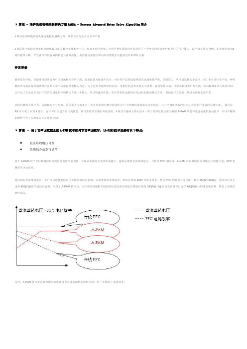
λ算法具备两大核心技术:用于调节电源功率因数的A-PAM功能和先进的电机驱动技术,可以在精简的硬件平台上实现单芯片室外机控制。
λ算法–用于功率因数校正的A-PAM技术在调节功率因数时,[A-PAM]技术主要有以下特点:∙直流母线电压可变∙系统综合效率可调节基于A-PAM,用户可以精确控制直流母线电压的输出值,在保证系统综合效率的前提下,提供足够的直流母线电压。
与传统PFC相比较,A-PAM可以限制直流母线电压的输出值,PFC电路效率也比较高。
瑞萨科技 CAN 应用手册

RCJ05B0027-0100/Rev.1.00
2006.02
Page 1 of 48
应用手册
3. CAN 是什么?
CAN 是 Controller Area Network 的缩写(以下称为 CAN),是 ISO*1 国际标准化的串行通信协议。 在当前的汽车产业中,出于对安全性、舒适性、方便性、低公害、低成本的要求,各种各样的电子控制系统 被开发了出来。由于这些系统之间通信所用的数据类型及对可靠性的要求不尽相同,由多条总线构成的情况很 多,线束的数量也随之增加。为适应“减少线束的数量”、“通过多个 LAN,进行大量数据的高速通信”的需 要,1986 年德国电气商博世公司开发出面向汽车的 CAN 通信协议。此后,CAN 通过 ISO11898 及 ISO11519 进 行了标准化,现在在欧洲已是汽车网络的标准协议。 现在,CAN 的高性能和可靠性已被认同,并被广泛地应用于工业自动化、船舶、医疗设备、工业设备等方面。 图 1 是车载网络的构想示意图。CAN 等通信协议的开发,使多种 LAN 通过网关进行数(BOSCH)公司所提出的 CAN 概要及协议进行了归纳,可作为实际应用中的参考资料。对于 具有 CAN 功能的产品不承担任何责任。
目录
1. 2. 概要 ................................................................................................................................................... 1 使用注意事项 ..................................................................................................................................... 1
新能源汽车关键系统电控技术

汽车电子的三个主要方向
绿色
安全
舒适
HEV/EV, Clean diesel Clean up emission
Active/Passive safety Driver Assistance
Car Navi/ITS, Body Multimedia, networking
HEV: Hybrid Electric Vehicle, EV: Electric Vehicle ITS: Intelligent Transport System
插电式 Plug-in HEV
全混 Full HEV 轻混 Mild HEV
常规动力车
发动机 驱动 启停系统 辅助电机 主驱电机 驱动 充电控制 模块
携带发电引擎
17
© 2012 Renesas Electronics (China) Co., Ltd. All rights reserved.
适用于EV/HEV 系统的市场技术趋势
Networking CAN LIN FlexRay SAFE-by-WIRE MOST Bluetooth
Infotainment Dashboard Car Audio Connectivity Audio Car Navigation Entertainment ITS/ GPS
Power MOS Driver
Renesas Nissan Leaf
Air Conditioner Compressor M16C
Inverter control SH, R8C Cluster V850, Mixed signal Navi SH, V850
限投影展示
Charger control SH, IGBT(PLC) Brake M32R, R8C, PoMOS Vehicle dynamic control M32R, R8C, PoMOS Battery control V850, Mixed signal
瑞萨科技SuperH系列微处理器

瑞萨科技SuperH系列微处理器
佚名
【期刊名称】《电子产品世界》
【年(卷),期】2006(000)12X
【摘要】瑞萨科技公司(Renesas Technology Corp.)推出具有片上以太网控制器的32位SuperH系列SH7652微处理器。
据称该器件集成了业界第一个加密/解密功能,以支持即将在日本启动的IP广播、用于家庭内部分配的DTCP—IP 版权保护标准,以及用于具有内置网络功能的数字视听和办公自动化设备的版权保护功能。
【总页数】2页(P32-33)
【正文语种】中文
【中图分类】TN492
【相关文献】
1.瑞萨科技SuperH族SH7080系列 [J],
2.瑞萨科技发布SH7619 32位SuperH系列微处理器具有片上以太网物理层收发器和以太网控制器 [J],
3.瑞萨科技发布带有片上闪存的SuperH系列SH7211F单芯片微控制器 [J],
4.瑞萨科技开发出SuperH系列SH72546RFCC [J],
5.瑞萨科技发布用于高性能多媒体系统的600MHz SuperH系列SH7785 [J],因版权原因,仅展示原文概要,查看原文内容请购买。
BLDC电机控制算法

BLDC电机控制算法BLDC(Brushless DC)电机是一种无刷直流电机,常用于工业和家用设备中。
它的控制算法起着至关重要的作用,可以决定电机的性能和稳定性。
下面将介绍一种基于瑞萨(Renesas)控制器的BLDC电机控制算法。
1.确定电机转速:从编码器或霍尔传感器中获取电机转速信息。
这个转速信息将用于后续步骤中的PWM(脉宽调制)控制。
2.确定电机位置:使用编码器或霍尔传感器确定电机的位置信息。
这个位置信息是电机控制的关键,因为它决定了电机相位的换向时间。
3.确定换向时机:根据电机的位置信息,确定下一个换向时机。
换向时机是指改变相位电流的时间点,以使转子保持在正确的位置。
这一步需要根据电机模型和性能要求进行计算。
4.设置相位电流:根据换向时机,确定要流经每个相位的电流大小和方向。
这一步需要通过PWM控制来实现。
PWM控制的原理是调整电流的开关时间和占空比,以实现所需的相位电流。
5.更新PWM控制:根据当前位置和期望电流,通过调整PWM控制算法中的参数,实现更准确的电流控制。
这可以通过PID(比例-积分-微分)控制器来实现,根据实际情况进行参数调整。
6.控制电机转速:通过调整相位电流和PWM控制算法中的参数,实现所需的电机转速和运动控制。
这可以通过增加或减少电流或调整换向时机来实现。
7.监控电机状态:通过传感器对电机的状态进行监测,包括电流、转速和温度,以确保电机正常工作和保护。
如果电机发生故障或超过安全工作范围,则应采取相应的措施,如停机或报警。
总结起来,BLDC电机控制算法的主要步骤包括获取转速和位置信息、确定换向时机、设置相位电流、更新PWM控制、控制电机转速和监控电机状态。
通过合理设计和实现这些步骤,可以实现BLDC电机的稳定、高效和精准控制。
2SK1317中文资料(renesas)中文数据手册「EasyDatasheet - 矽搜」

5.瑞萨科技半导体产品不是设计或在设备制造中使用 或根据情况使用系统中,人生命是潜在威胁.请联系 瑞萨科技公司或考虑使用此报告任何特定目,如设备或系统,运输,车辆,医疗,航空航天,核 能,或海底中继器使用一个产品时,经授权瑞萨科技产品经销商.
3.包含在这些资料,包括产品数据,图,表,程序和所有信息 算法表示在公布这些材料时间对产品信息,并有可能由株式会社瑞萨科技,恕不另行通知变动,由 于产品改进或其他原因.因此,建议客户购买此处所列产品之前,请联系瑞萨科技公司或瑞萨 科技公司授权产品分销商最新产品信息.
这里描述信息可能包含技术错误或印刷错误. 瑞萨科技公司不承担任何损害,责任或其他损失,这些不准确或错误上升不承担任何责任.
°C )
在这一领域
由R限于
DS (on)
Ta = 25°C
0.01 10 30 100 300 1,000 3,000 10,000
漏极至源极电压V
DS (V)
典型传输特性
2.0
1.6 (A)
D
1.2
VDS = 20 V
脉冲测试
0.8 漏电流I
0.4
75°C TC = 25°C
–25°C
0
2
4
门源电压V
6 8 10 GS (V)
3
额定值
单元
1500
V
±20
V
2.5
A
7
A
2.5
A
瑞萨科技公司(混响IC).

瑞萨科技公司(Renesas Technology Corp.)最近发布了两款用于卡拉OK 机、DVD 播放机、大功率阴极射线管电视(CRT-TV)和用于中美洲和南美洲的无线盒式播放机等的单芯片回波IC 。
该产品具有两倍于瑞萨科技以前产品的44Kb 回波RAM 容量的R2A15906SP ,以及包括了得分功能的R2A15907SP 。
这两款新产品的主要的特性如下:1. 业界最大容量的44Kb 片上回波RAM 容量单芯片产品:为了满足市场对更高音质的需求,存储回波声音信号RAM 容量已经增加到了44Kb ,这是瑞萨科技以前产品的两倍。
它也是业界单芯片卡拉OK 回波IC 最大的回波RAM 容量,可以准确而自然地对回波进行设置。
2. R2A15907SP 的片上得分功能:R2A15907SP 是业界第一个具有得分功能的单芯片回波IC 。
其得分功能采用了瑞萨科技原创的M65851FP 单芯片卡拉OK 处理器的专有算法,R2A15906SP 回波IC 中的得分功能有助于减少系统尺寸和成本。
R2A15906SP 和R2A15907SP 在引脚排列方面具有兼容性,有助于使用一个通用系统电路板。
3. 片上外设功能包括麦克风音量控制、放大器和集成互连总线(I 2C)接口,等等。
几乎所有回波IC 的外设功能都在片上提供,包括用于调整麦克风输入信号电平的自动电平控制(ALC)放大器、音调调整功能和回波级数调整功能,使回波系统可以用一个单芯片进行配置。
已经集成的集成互连总线(I 2C 总线)接口有助于安装各种应用,简化外部控制。
利用增加的RAM 容量改善音质:增加回波容量是改善歌唱声音清晰度和音调的最有效的方法。
从瑞萨科技当前的M65850FP 卡拉OK 回波IC 的20Kb 增加到44Kb 的加倍RAM 容量,有助于创建更精确和自然回波效果。
瑞萨科技的单芯片回波IC---R2A15906SP 和R2A15907SP 。
瑞萨PMSM电机位置控制
APPLICATIONNOTE RX62T R01AN0899EU0100Rev. 1.00Position Control of PMSM Motors with EncoderNov. 18, 2011IntroductionThis document presents RX62T position control with a permanent magnet synchronous motor, which has beenimplemented on RX62T evaluation kit with hall sensors and encoder.The document describes hardware platform, methodology of position control, control block diagram, software structure,and flow chart of the position measurement and control.The solution in application note has been implemented with RX62T evaluation kit and a 3-phase 8-pole 24V PMSMmotor with a 1000 line single–ended encoder.Target DeviceRX62TContents1.Overview (2)2.System Hardware Setup and Structure (3)3.Specification and Performance Data (4)4.RX62T Encoder Capture Function (5)5.Encoder Based Position and Speed Calculation (8)6.Position Control Strategy (11)7.Software Description (15)8.Motor and Position Control Parameters (19)Appendix A - References (21)1. OverviewPosition control plays an important role in various areas such as automation industry, semiconductor industry, etc. Permanent magnet synchronous motors (PMSM) are ideal for advanced position control systems for their potentials of high efficiency, high torque to current ratio, and low inertia, have been widely used in the industrial fields. Various approaches have been made to realize high performance motion control.With successively improving reliability and performance of digital controllers, advances in Microprocessors (MCU) have greatly enhanced the potential of PMSM in servo position control applications. Digital control can be implemented by MCUs, which make it superior to analog based stepper control, since the controller is much more compact, reliable, and flexible. High performance of PMSM can be obtained by means of field oriented control, which is only realizable in a digital based system.RX62T is a 32-bit high-performance microcontroller with a maximum operating frequency of 100MHz and 165 DMIPS and single precision floating-point unit (FPU), which is equipped with multifunction timers (MTU, GPT), high-speed 12-bit A/D converter and encoder signal capture for facilitating servo motion control.In this application note, a RX62T floating point unit (FPU) based position motion control system is proposed. Position regulation is developed to provide both a trajectory generator and a PID controller, which ensures accurate position control and fast tracking. The trajectory generator provides position set-point commands. The position PID controller operates on the position error and outputs a current command. The current regulation with field oriented control is implemented to secure fast dynamic response.Software developed is applicable to following devices and platforms.MCU: RX62T and RX62NMotor: three-phase permanent magnetic synchronous motors (PMSM)Platform: Renesas RX62T demo kitControl algorithm: Encoder based position control2. System Hardware Setup and StructureRX62T FPU based position control is implemented with Renesas RX62T evaluation kit and a three-phase PMSM motor with a1000 line single-ended encoder as shown in Figure 1.RX62T evaluation kit is a single board inverter, based on the RX series microcontroller RX62T.A complete 3-phase inverter on-board with a low voltage motor24Vexternal power supply to provide DC bus voltage, 15V and 5V power supplyPower devices use Renesas low voltage MOSFETsPower rate up to 120wattsSupport 3 shunt and single shunt current measurementEasily jumper change from the external amplifiers to the internal PGAUSB communication with the PC via a H8S2212 MCUUser GUI to modify motor and control parameters, tune both speed and position controlConnectors for hall sensors and encoder connectionsLCD display to monitor the operation statusSupport the standalone mode set by potentiometer and push buttonsSupport the second motor drive, signals and connector for another motor control power stage are available The motor is a 24V 4 pair poles 3-phase permanent magnetic synchronous motor with3 hall sensors1000 line quadrature encoderFigure 1 System hardware setup (motor and control platform)3. Specification and Performance DataThe implementation of position control is based on Renesas evaluation kit and RX62T MCU, the main specification data are described as following:Input voltage: 24VDCRated bus voltage: 24VOutput voltage: 24VACRated output power: 120WPWM Switch frequency: 20KHzControl loop frequency: 10KHzCurrent measurement: 3 shunt resistorsPosition measurement: 1000 line quadrature encoderImplementation: FPUCPU bandwidth: 17%Used flash memory: 13.444KbytesUsed RAM: 1.725KbytesUsed stack : 336bytes4. RX62T Encoder Capture FunctionThe RX62T is a 32-bit high-performance microcontroller with a maximum operating frequency of 100MHz and 165 DMIPS and single precision floating-point unit (FPU), which is equipped with multifunction timers (MTU, GPT), high-speed 12-bit A/D converter, and 10-bit A/D converter for facilitating motor control. Figure 2 shows the block diagram of a senorless vector control of PMSM motors based on the Renesas RX62T Microcontroller.RX62T has a dedicate function for the encoder measurement as depicted in Figure 2. MTU3 timer external clock input TCLKA, TCLKB, TCLKC, and TCLKD can be used for two-phase encoder pulse inputs. When the MTU3 timer of Channels 1 and 2 are specified by the phase counting mode, an external encoder clock is selected as the counter input clock and TCNT operates as an up/down-counter. The phase difference between two external input clocks is detected and TCNT is incremented or decremented accordingly. The rotor position and speed can be measured by reading the TCNT counts.The following summarizes the MTU3 function for the encoder pulse counting functionality:MTU Channel 1 & 2 support 2-phase pulse counting mode which is called “Phase Counting Mode”This function covers 4 modesAt these modes, the counter works as up/down counter. And it is possible to detect the direction of counter with the flag.Up/down count by detecting phase difference between phase A and B of encoder on mode1 and mode 4 o Mode 1: every rising edge & falling edge of both of encoder pulseo Mode 4: every rising edge & falling edge of phase B encoder plusesUp/down count by two pulse lines which indicate the direction, speed and position.o Mode 2: One pulse line and One directiono Mode 3: Two pulse lines for each directionMTU can detect automatically speed and position data as the pulse width & the pulse. The data of speed and position can be captured every periodic cycle.In this application, the encoder pulse A and B are input to the TCLKA and TCLKB. The Z pulse is to IRQ0. For the second motor, the encoder pulse A and B are input to the TCLKC and TCLKD. The Z pulse is to IRQ3.The host communication using the graphic user interface (GUI) is communicated with the RX62T MCU by the USB communication. It can display the motor operation status in the real time, tune the motor and control parameters, and drive the motor for both speed control and position control.Figure 2 RX62T encoder capture functionalityTable 1 lists the timer register function for Channel 0 to 2 for the encoder capture. The timer MTU enable to automatically detect both the pulse width and the number of pulse of encoder every speed control loop period. It is not necessary of external wiring for any trigger signals. The encoder signals are directly input to Timer external clock; TCLKA and TCLKB as clock source of channel, and also, input command pulse to Timer external clock; TCLKC and TCLKD as clock source of Channel 2.Channel 1 counter is counted by every falling edge and rising edge of encoder pulse.Channel 0 is used for interval time to generate input capture trigger of Channel 1 and Channel 2, and interrupt of speed control loop.Channel 2 measures pulse command input.Channel 0 compare match (speed control loop period) can be selected as input capture trigger for Channel 1 internally.Channel 1 and Channel 2 external timer clock (encoder pulse or command pulse) can be selected as input capture trigger for Channel 0 internally.Table 1 MTU timer registers functionFigure 3 shows how the MTU captures the encoder signals in phase counting mode. The Channel 1 is coupled with Channel 0 to input 2-phase encoder pulses of a servo motor in order to detect position or speed. Channel 1 is set to phase counting mode 1, and the encoder pulse A-phase and B-phase are input to MTCLKA and MTCLKB. In Channel 0, MTU3_0.TGRC compare match is specified as the TCNT clearing source and MTU3_0.TGRA and MTU3_0.TGRC are used for the compare match function and are set with the speed control cycle and position control cycle. MTU3_0.TGRB is used for input capture, with MTU3_0.TGRB and MTU3_0.TGRD operating in buffer mode. The Channel 1 counter input clock is designated as the MTU3_0.TGRB input capture source, and the widths of 2-phase encoder 4-multiplication pulses are detected. MTU3_1.TGRA and MTU3_1.TGRB for Channel 1 are designated for the input capture function and MTU3_0.TGRA and MTU3_0.TGRC compare matches in Channel 0 are selected as the input capture sources to store the up/down-counter values for the control cycles.Therefore, the RX62T MTU itself can realize precise detection of the pulse width and the number of pulses,which are needed to estimate motor speed and position. It doesn’t need the load of the CPU hardly to detectthose. Also the MTU is able to receive the pulse command as well.Figure 3 Encoder pulse capture in phase counting mode5. Encoder Based Position and Speed Calculation5.1 Position and Speed MeasurementA digital encoder outputs three pulse trains: A,B and Z, as shown in Figure 4. These pulses are fed into a timer unit TCLKA and TCLKB that counts events. Pulses A and B are offset by 1/4th of the distance to give a 90-degree offset, so they are known as quadrature counts. Pulse Z occurs only once per rotation. It is fed into the interrupt input (IRQ0) and zeroes out (resets) the counter MTU2_TCNT. When the pulse Z occurs, the rotor angle with respect to the stator frame produces a definite value, preferably zero. If this value is not zero, it is a constant offset that can be measured. Quadrature counters are designed to count these pulses up or down, depending on whether A comes before or after B. That is, the relationship between A and B indicates the direction of rotation.Figure 4 Relationship among the digital encoder pulses A, B and ZThe encoder has been aligned and calibrated with Hall sensor U with zero initial position. The angle is zero count when the Z pulse occurs through the external interrupt IRQ0. From this point onwards it is given a certain count value as the quadrature counter is read. As shown in Figure 5, the phase counting mode 1 is used to up/down count by detecting phase difference between A and B phase. These counts are transformed into a proper angle value for the rotor position.Figure 5 Encoder counting mode operationMotor speed determines how much the angle of the rotor changes over time. As shown in Figure 6, pulses A and B from the encoder are used at the control loop rate. Two angles are measured at constant time intervals, thus giving the measurements needed to compute speed: delta angle and delta time. Speed is computed by dividing the delta angleθΔby the delta time.The motor position is the number of the encoder pulse as N(m)-N(m).θΔ = N(m+1) – N(m)and the motor speed isω = (N(m+1)-N(m)) /TsprFigure 6 Speed calculation using encoder pulses A and B at control loop rate5.2 Initial Position IdentificationIncremental encoders can only give displacements from the initial position and can’t provide absolute position. For PMSM motor and position control, the initial position is required. Although alignment has been calibrated, the initial starting position before the Z pulse is still unknown.By means of Hall sensors the rotor initial position can be identified, and further corrected when the rotor starts rotating. Assuming the Hall sensors are located at each phase, as shown in Figure7. The output signals of the Hall sensors are illustrated in Figure 8. It can be seen that the resolution of the Hall sensor signals are 60° (electrical degree). Table 1 shows the possible combinations corresponding to different positions.Figure 7 Hall sensors for initial rotor positionFrom Figure 8 and Table 2, given a specific Hall sensor output combination, the rotor must reside in certain section with a range of 60°. The initial position is determined as follows. When a group of output signals are obtained, for example, (101), we can decide which section the rotor is in (section 1 in this example). We can set the initial position at the center of the section (30° in this example). It can be seen that the maximum error of the initial position is 30°, which occurs when the rotor is at the edge of two regions. However, even with 30° error, the motor is still able to produce sufficient torque to start the motor.Once the motor starts rotating, the position can be readily corrected when the rotor moves out of the initial region and enters the next section. This position is accurate. In the previous example, when the motor starts rotating in the positive direction from section 1, the rotor position can be corrected when the position is 60°.Table 2 Relationship between hall sensors and rotor position Section Hu Hv Hw RotorPosition1 1 0 1 0~602 1 0 0 60~1203 1 1 0 120~1804 0 1 0 180~2405 0 1 1 240~3006 0 0 1 300~360Figure 8 Hall sensor output signals6. Position Control Strategy6.1 Block Diagram of Position ControlFigure 9 is block diagram of position control. The position control developed includes two loops. The outer loop is position control to make the motor tracking and holding the given position. The inner loop is current control. Actually it is the torque control loop. The motor currents are sampled through three shunt resistors and converted into the dq axis currents. The control loop here is to control the q axis current for the torque.Figure 9 Block diagram of position controlThe position control scheme of the PMSM is illustrated in Figure10. The system has an inner loop of current regulation using vector control, and an outer loop of position regulation. This dual-loop structure ensures the fast torque response by using the vector control, high position accuracy and fast tracking performance with the position controller.In order to determine the d and q axis currents, the phase currents must be measured. Vector formulation uses Clarke and Park transforms to convert the measured phase currents from the (u, v, w) frame to first transform them in the static orthogonal (a,ß) frame (which is 90 degrees apart), and then, to the rotor frame which is also an orthogonal frame aligned along the magnetic field axes known as the (d,q) frame. These transformations use the transcendental functions sine and cosine of the rotor angle; thus, it is a requirement that the rotor angle is known at the time the calculation is made. The position control requires current sensors, plus an encoder attached to the rotor shaft to measure the rotor position.Once the currents are transformed in the (d,q) frame, the control algorithm simply runs the PID or PI loop to calculate the required voltages for the torque and flux. These required voltages (Vdc, Vqc) are then transformed back in the (u, v, w) frame using the inverse Clarke and inverse Park transforms to further calculate the PWM duty cycle.The position command is an input to the position control system. The motor has an encoder mounted on its rotor to give the quadrature pulses A and B, as well as the zero synch pulse Z. All three of the rotor position signals are sent to the MCU’s input-capture and timer/quadrature counter peripheral for making position and speed measurements. The commanded position compares with the actual rotor position. The position regulator uses the traditional PID controller, and outputs the torque control command of iq* to make the motor moving and tracking the commanded position.Figure 10 Position control scheme diagram6.2 Position Control Loop DesignThe basic components of a typical servo position control system are depicted in Figure11. In this figure, the servo position control closes a current loop as described in next section and is modeled simply as a linear transfer function Gireg(s). Of course the servo drive has peak current limits, so this linear model is not entirely accurate; however it does provide a reasonable representation for analysis. For the purposes of this discussion the transfer function of the current regulator or really the torque regulator can be approximated as unity for the relatively lower motion frequencies.Figure 11 Position PID controller topologyThe PMSM motor is modeled as a lump inertia J, a viscous damping term B, and a torque constant Kt. The lump inertia term is comprised of both the servomotor and load inertia. It is also assumed that the load is rigidly coupled such that the torsional rigidity moves the natural mechanical resonance point well out beyond the position controller’s bandwidth. Thisassumption allows us to model the total system inertia as the sum of the motor and load inertia for the frequencies that can be controlled.An encoder coupled directly to the motor shaft measures the actual motor position θ(s). External shaft torquedisturbances Td are added to the torque generated by the motor's current to give the torque available to accelerate the total inertia J.Around the current regulator, motor block is the servo position controller that closes the position loop. The basic servo position controller provides both a trajectory generator and a PID controller. The trajectory generator provides only position set-point commands labeled in Figure 9 as θ*(s). The PID controller operates on the position error and outputs a current command.There are three gains to adjust in the PID controller, Kp, Ki and Kd. These gains all act on the position error defined as:)()(*s s θθθ−=ΔNote the superscript “*” refers to a commanded value.The output of the PID is given mathematically in the time domain as:)()()()(*t dtdK dt t K t K t iq di p θθθΔ+Δ−Δ=∫ Loosely speaking, the proportional term affects the overall response of the system to a position error. The integral term is needed to force the steady state position error to zero for a constant position command and the derivative term is needed to provide a damping action, as the response becomes oscillatory. Unfortunately all three parameters are inter-related so that by adjusting one parameter will affect any of a previous parameter adjustment.Tuning the PID controller can be done if the motor and load parameters are known and the desired frequency response are known. They are adjusted using the following parameters in the header file of “customize.h”.6.3 Current Control LoopThe current loop is a standard PI type based on the standard Park-Clarke stationary reference frame to rotary reference transformations. The initial rotor position is determined by use of the Hall sensors. Once a Hall transition occurs, the rotor position is then determined by reading the incremental encoder. The basic block diagram for the current vector control is shown in Figure 12.Figure 12 Block diagram of current vector controlNeglecting motor saliency, the commanded q axis current, iq* is linearly related to the commanded torque. The “d” axis current command, id* is set to zero as field weakening is not required. The transformation takes two steps. First, the stationary currents are transformed to an arbitrary stationary pair of orthogonal axes α, β and second, the axes are then rotated to the rotor axes for control purposes.The typical current PI controller is depicted in Figure 13. Kp and Ki are the proportional gain and integration gain, respectively, which can be adjusted by the software. The hardware gain Kb takes into account the bus voltage.Figure 13 Current PI controller topologyThe transfer function of the block diagram is:⎟⎠⎞⎜⎝⎛+⎟⎟⎠⎞⎜⎜⎝⎛++⎟⎠⎞⎜⎝⎛+⎟⎟⎠⎞⎜⎜⎝⎛=LK K s L R K K s L K K s L K K s i s i bi b p b i b p 2*)()(It has a characteristic equation in the form of:022002=++ωξωs sTherefore:bp K RL K −=02ξωbi K LK 20ω=The system exhibits the standard second order response with the addition of a real zero. To tune the system, the high frequency of 500Hz needs to be first set for Kp, and then slowly increase the integral term Ki to bring our steady state error to zero.7. Software Description7.1 Overall Software StructurePosition control algorithm is implemented with the complete C code using Renesas’ RX62T MCU floating point unit. The overall software structure is shown in Figure 14.Figure 14 Position software architectureThe procedures include:initializations of RX62T MCU, motor and control parameterscurrent offsets calculationbus voltage and phase currents measurementshall sensor and encoder readinginitial position identificationrotor position calculationvector control transformationmotion profile - trajectory generationposition regulatorcurrent controllersPWM duty calculationspace vector PWM generation7.2 Software HEW WorkspaceShown in Figure 15 is the workspace for position control using Renesas’ HEW compiler.All codes are written in the floating point C language;The software is modularized according to the position control block diagram (as shown in Figure10);I/O definitions and basic MCU drivers are automatically generated by HEW;Motor and control parameters are easily tuned through a header file of “customize.h” and GUI user interface. The codes include dbsct.c; hwsetup.c, intprg.c; main.c; mcrplibf.c; motorcontrol.c; resetprg.c; userif.c and vectbl.c.dbsct.c includes structures used by the runtime library both to clear un-initialized global variables and to write initial values into initialized global variable sections.hwsetup.c is hardware initializations.vecttbl.c contains the array of addresses of ISRs.resetpr.c has functions called just after reset.intprg.c is entry points for all of standard ISRs vectors.main.c including: initialization of control parameters, MTU3 timer, interrupts, serial communication, encoder capture definitions; and uploading eeprom parameters. The current sensor offsets are calculated before theoutput of PWMs. The while loop executes parameter update and SCI communication with graphic user interface.The motorcontrol.c is a major code for position control, which contains most of functions and function calls to implement position control.Mcrplibf.c mainly includes vector control transformations – Clarke, Park, and inverse Clarke and Park transformations, and sine and space vector PWM generation.Figure 15 Encoder counting mode operation position control software workspace7.3 Hall and Encoder Based Position and Speed MeasurementFigure 16 is a flowchart of position measurement. The procedures for the position measurement based on hall sensors and encoder are:Initialize hall sensor and encoder capture timer registers and I/O ports;Identify the rotor initial position using hall sensor;Move the motor to capture the position using encoder pulses;Calibrate the rotor position once the hall commutation changes;After calibration, recalculate the rotor position;Check encoder Z pulse and reset the position offset and encoder pulse capture timer count;Calculate the rotor position and motor speed.Figure 16 Encoder counting mode operation Flowchart of position and speed measurement7.4 PWM Interrupt for Position ControlThe position profile generation and position control are put in the PWM interrupt with 16 kHz carrier frequency. Figure 17 is a flowchart of PWM interrupt.The procedures in the PWM interrupt of MC_ConInt () are:Measure motor phase motor currents and DC bus voltage;Calculate motor position and speed using hall sensors and encoder;Transfer motor currents into dq currents;Current control loop;Update trajectory generator and position profile;Position control loop;PWM generation using space vector PWM modulation or sinusoidal PWM modulation.Figure 17 Flowchart of PWM interrupt for position control8. Motor and Position Control Parameters8.1 Tuning through header fileAccording to the motor data sheet and position control requirements, motor and control parameters, and motion profile should be properly tuned.Motor and control parameters required in the code of “customize.h” include:#define ENC_EDGES_CUSTOM 4000 // total encoder Edges/Revolution#define PWM_FREQ_CUSTOM 16000 // PWM Frequency in Hz#define SAM_FREQ_CUSTOM 16000 // Sample Frequency in Hz#define C_POLI_CUSTOM 4 // polar couples number#define R_STA_CUSTOM 8 // stator phase resistance in Ohm/OHM_DIV#define L_SYN_CUSTOM 10 // synchronous inductance in Henry/HEN_DIV#define POS_MIN_CUSTOM 0 // minimum position in counts#define POS_MAX_CUSTOM 40000 // maximum position in counts#define KP_CUR_CUSTOM 60 // K prop. current control#define KI_CUR_CUSTOM 80 // K integ. current control#define K_P_POSITION 10 // K prop. position control#define K_I_POSITION 12 // K integ. position control#define K_D_POSITION 150 // K derivative psotion control8.2 Operation through GUIThe motor and control parameters can be tuned through Renesas friendly graphic user interface as shown in Figure 18. Without modifying the code, the parameters can be set for the different motors and applications. There is a parameter window to set up 20 parameters. Scrolling up and down through these parameters, the user can make changes to the settings, and “Write” to EEPROM, but this doesn’t change the “customize.h” file. The original values will be restored upon RESET. From Figure 19, it can be seen that these parameters mirror the #defines in the “customize.h” file. The motor and control parameters can be easily changed by the GUI.In the meantime, the GUI has position control window to set the commanded position, and display the motor actual operation status.Figure 18 GUI interface of evaluation kitFigure 19 Parameter windowAppendix A - References1.RX62T Group User’s Manual: Hardware, R01UH0034EJ0110, April 20, 20112.DevCon 2010 Courses:ID-620C, Complete Motor Control Integration with RX62T.ID 623C, Understanding Sensor-less Vector Control with Floating Point Unit (FPU) Implementation.3.DevCon 2008 Courses:ID-504, Speed Control using a Digital Encoder and Vector Formulation4.Application Note of Sensorless Vector Control of three-phase PMSM motors, REU05B0103-0100/Rev.1.00,March, 20095.Application Note of Mcrp05: Brushless AC Motor Reference Platform, REU05B0051-0100, Feb, 2009Website and SupportRenesas Electronics Website/Inquiries/inquiryAll trademarks and registered trademarks are the property of their respective owners.Revision RecordDescriptionRev. Date Page Summary 1.00 Nov. 18, 2011. — First edition issuedGeneral Precautions in the Handling of MPU/MCU ProductsThe following usage notes are applicable to all MPU/MCU products from Renesas. For detailed usage notes on the products covered by this manual, refer to the relevant sections of the manual. If the descriptions under General Precautions in the Handling of MPU/MCU Products and in the body of the manual differ from each other, the description in the body of the manual takes precedence.。
瑞萨电子ISL2110、ISL2111 100V、3A 4A Peak高频半桥驱动器说明书
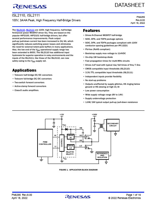
FN6295Rev.8.00April 18, 2022ISL2110, ISL2111100V, 3A/4A Peak, High Frequency Half-Bridge DriversDATASHEETThe ISL2110, ISL2111 are 100V, high frequency, half-bridge N-Channel power MOSFET driver ICs. They are based on the popular HIP2100, HIP2101 half-bridge drivers, but offer several performance improvements. Peak outputpull-up/pull-down current has been increased to 3A/4A, which significantly reduces switching power losses and eliminates the need for external totem-pole buffers in many applications. Also, the low end of the V DD operational supply range has been extended to 8VDC. The ISL2110 has additional input hysteresis for superior operation in noisy environments and the inputs of the ISL2111, like those of the ISL2110, can now safely swing to the V DD supply rail.Applications•Telecom half-bridge DC/DC converters •Telecom full-bridge DC/DC converters •Two-switch forward converters •Active-clamp forward converters •Class-D audio amplifiersFeatures•Drives N-Channel MOSFET half-bridge •SOIC, DFN, and TDFN package options•SOIC, DFN, and TDFN packages compliant with 100V conductor spacing guidelines per IPC-2221•Pb-free (RoHS compliant)•Bootstrap supply max voltage to 114VDC •On-chip 1W bootstrap diode•Fast propagation times for multi-MHz circuits•Drives 1nF load with typical rise/fall times of 9ns/7.5ns •CMOS compatible input thresholds (ISL2110)•3.3V/TTL compatible input thresholds (ISL2111)•Independent inputs provide flexibility •No start-up problems•Outputs unaffected by supply glitches, HS ringing below ground or HS slewing at high dv/dt •Low power consumption•Wide supply voltage range (8V to 14V)•Supply undervoltage protection•1.6W/1W typical output pull-up/pull-down resistanceFIGURE 1.APPLICATION BLOCK DIAGRAMSECONDARY CIRCUIT+100VC O N T R O LCONTROLLERPWMLIHIHO LOV DDHSHB+12V V SSREFERENCEAND ISOLATIONDRIVE LODRIVE HIISL2110ISL2111Functional Block DiagramFIGURE 2.FUNCTIONAL BLOCK DIAGRAMUNDER VOLTAGEV DDHILI V SSDRIVERDRIVERHBHOHSLOLEVEL SHIFTUNDER VOLTAGEEPAD (DFN Package Only)ISL2111ISL2111*EPAD = Exposed Pad. The EPAD is electrically isolated from all other pins. For best thermal performance, connect the EPAD to the PCB power ground plane.Application DiagramsSECONDARY ISOLATIONPWM+48V+12VCIRCUITFIGURE 3.TWO-SWITCH FORWARD CONVERTERISL2110ISL2111SECONDARY CIRCUITISOLATIONPWM+48V+12VFIGURE 4.FORWARD CONVERTER WITH AN ACTIVE-CLAMPISL2110ISL2111Ordering InformationPART NUMBER (Notes2, 3)PARTMARKINGPACKAGE DESCRIPTION(RoHS COMPLIANT)PKG.DWG. #CARRIER TYPE(Notes1)TEMP RANGEISL2110ABZ 2110ABZ 8 Ld SOIC M8.15Tube-40 to +125°CISL2110ABZ -T Reel, 2.5kISL2110AR4Z2110AR4Z 12 Ld 4x4 DFN L12.4x4A TubeISL2110AR4Z-T Reel, 6kISL2111ABZ2111ABZ 8 Ld SOIC M8.15TubeISL2111ABZ-T Reel, 2.5kISL2111AR4Z2111AR4Z 12 Ld 4x4 DFN L12.4x4A TubeISL2111AR4Z-T Reel, 6kISL2111ARTZ2111ARTZ 10 Ld 4x4 TDFN L10.4x4TubeISL2111ARTZ-T Reel, 6kISL2111BR4Z2111BR4Z 8 Ld 4x4 DFN L8.4x4TubeISL2111BR4Z-T Reel, 6kNOTES:1.See TB347 for details about reel specifications.2.These Pb-free plastic packaged products employ special Pb-free material sets, molding compounds/die attach materials, and 100% matte tin plateplus anneal (e3 termination finish, which is RoHS compliant and compatible with both SnPb and Pb-free soldering operations). Pb-free products are MSL classified at Pb-free peak reflow temperatures that meet or exceed the Pb-free requirements of IPC/JEDEC J STD-020.3.For Moisture Sensitivity Level (MSL), please see device information page for ISL2110, ISL2111. For more information on MSL, see TB363.Pin ConfigurationsISL2111ARTZ (10 LD 4x4 TDFN)TOP VIEW ISL2110AR4Z, ISL2111AR4Z(12 LD 4x4 DFN)TOP VIEW2 3 4 1 59 8 7 10 6VDD HB HO HS NC LOVSSLIHINCVDDNCNCHBHOLOVSSNCNCLIHS HI234151110912867EPAD**EPAD = EXPOSED PADISL2110ABZ, ISL2111ABZ(8 LD SOIC)TOP VIEWISL2111BR4Z (8 LD 4x4 DFN)TOP VIEWPin Configurations56874321VDD HB HO HSLO LI HIVSS 23417658VDD HB HO HSLO VSS LI HIEPAD**EPAD = EXPOSED PADPin DescriptionsSYMBOL DESCRIPTIONVDD Positive supply to lower gate driver. Bypass this pin to VSS.HB High-side bootstrap supply. External bootstrap capacitor is required. Connect positive side of bootstrap capacitor to this pin. Bootstrap diode is on-chip.HO High-side output. Connect to gate of high-side power MOSFET.HS High-side source connection. Connect to source of high-side power MOSFET. Connect negative side of bootstrap capacitor to this pin. HI High-side input LI Low-side inputVSS Chip negative supply, which will generally be ground.LO Low-side output. Connect to gate of low-side power MOSFET.NC No connectEPADExposed pad. Connect to ground or float. The EPAD is electrically isolated from all other pins.Absolute Maximum Ratings Thermal InformationSupply Voltage, V DD, V HB - V HS (Notes4, 5) . . . . . . . . . . . . . . . 0.3V to 18V LI and HI Voltages (Note5) . . . . . . . . . . . . . . . . . . . . . . .-0.3V to V DD + 0.3V Voltage on LO (Note5). . . . . . . . . . . . . . . . . . . . . . . . . . .-0.3V to V DD + 0.3V Voltage on HO relative to HS (Repetitive Transient < 100ns). . . . . . . . .-2V Voltage on LO relative to GND (Repetitive Transient < 100ns). . . . . . . .-2V Voltage on HO (Note5) . . . . . . . . . . . . . . . . . . . . . .V HS - 0.3V to V HB + 0.3V Voltage on HS (Continuous) (Note5). . . . . . . . . . . . . . . . . . . . . -1V to 110V Voltage on HB (Note5) . . . . . . . . . . . . . . . . . . . . . . . . . . . . . . . . . . . . . .118V Average Current in V DD to HB Diode . . . . . . . . . . . . . . . . . . . . . . . . . 100mA Maximum Recommended Operating ConditionsSupply Voltage, V DD. . . . . . . . . . . . . . . . . . . . . . . . . . . . . . . . . . . . . 8V to 14V Voltage on HS . . . . . . . . . . . . . . . . . . . . . . . . . . . . . . . . . . . . . . . . -1V to 100V Voltage on HS . . . . . . . . . . . . . (Repetitive Transient < 100ns) -5V to 105V Voltage on HB . . . . . . . . . . .V HS+7V to V HS+14V and V DD - 1V to V DD+100V HS Slew Rate. . . . . . . . . . . . . . . . . . . . . . . . . . . . . . . . . . . . . . . . . . . .<50V/ns Thermal Resistance (Typical)θJA (°C/W)θJC (°C/W) 8 Ld SOIC (Notes6, 9) . . . . . . . . . . . . . . . . . 954610 Ld TDFN (Notes7, 8) . . . . . . . . . . . . . . . 40 2.512 Ld DFN (Notes7, 8) . . . . . . . . . . . . . . . . 39 2.58 Ld DFN (Notes7, 8). . . . . . . . . . . . . . . . . . 40 4.0 Max Power Dissipation at +25°C in Free Air8 Ld SOIC (Notes6, 9). . . . . . . . . . . . . . . . . . . . . . . . . . . . . . . . . . . . . . .1.3W 10 Ld TDFN (Notes7, 8) . . . . . . . . . . . . . . . . . . . . . . . . . . . . . . . . . . . . .3.0W 12 Ld DFN (Notes7, 8) . . . . . . . . . . . . . . . . . . . . . . . . . . . . . . . . . . . . . .3.1W 8 Ld DFN (Notes7, 8). . . . . . . . . . . . . . . . . . . . . . . . . . . . . . . . . . . . . .3.1W Storage Temperature Range. . . . . . . . . . . . . . . . . . . . . . . .-65°C to +150°C Junction Temperature Range . . . . . . . . . . . . . . . . . . . . . . .-55°C to +150°C Pb-Free Reflow Profile. . . . . . . . . . . . . . . . . . . . . . . . . . . . . . . . . . see TB493CAUTION: Do not operate at or near the maximum ratings listed for extended periods of time. Exposure to such conditions may adversely impact product reliability and result in failures not covered by warranty.NOTES:4.The ISL2110 and ISL2111 are capable of derated operation at supply voltages exceeding 14V. Figure 24 shows the high-side voltage derating curvefor this mode of operation.5.All voltages referenced to V SS unless otherwise specified.6.θJA is measured with the component mounted on a high-effective thermal conductivity test board in free air. See Tech Brief TB379 for details.7.θJA is measured in free air with the component mounted on a high-effective thermal conductivity test board with “direct attach” features. See TechBrief TB379.8.For θJC, the “case temp” location is the center of the exposed metal pad on the package underside.9.For θJC, the “case temp” location is taken at the package top center.Electrical Specifications V DD = V HB = 12V, V SS = V HS = 0V, no load on LO or HO, unless otherwise specified.PARAMETERS SYMBOL TEST CONDITIONST J = +25°C T J = -40°C to +125°CUNIT MIN(Note10)TYPMAX(Note10)MIN(Note10)MAX(Note10)SUPPLY CURRENTSV DD Quiescent Current I DD ISL2110; LI = HI = 0V- 0.100.25-0.30mA V DD Quiescent Current I DD ISL2111; LI = HI = 0V- 0.300.45-0.55mA V DD Operating Current I DDO ISL2110; f = 500kHz- 3.4 5.0- 5.5mA V DD Operating Current I DDO ISL2111; f = 500kHz- 3.5 5.0- 5.5mA Total HB Quiescent Current I HB LI = HI = 0V-0.100.15-0.20mA Total HB Operating Current I HBO f = 500kHz- 3.4 5.0- 5.5mA HB to V SS Current, Quiescent I HBS LI = HI = 0V; V HB = V HS = 114V-0.05 1.50-10µA HB to V SS Current, Operating I HBSO f = 500kHz; V HB = V HS = 114V- 1.2---mA INPUT PINSLow Level Input Voltage Threshold V IL ISL2110 3.7 4.4- 3.5-V Low Level Input Voltage Threshold V IL ISL2111 1.4 1.8- 1.2-V High Level Input Voltage Threshold V IH ISL2110- 6.67.4-7.6V High Level Input Voltage Threshold V IH ISL2111- 1.8 2.2- 2.4V Input Voltage Hysteresis V IHYS ISL2110- 2.2---VInput Pull-Down Resistance R I-210-100500k ΩUNDERVOLTAGE PROTECTION V DD Rising Threshold V DDR 6.1 6.67.1 5.87.4V V DD Threshold Hysteresis V DDH -0.6---V HB Rising Threshold V HBR 5.5 6.1 6.8 5.07.1V HB Threshold Hysteresis V HBH-0.6---VBOOTSTRAP DIODELow Current Forward Voltage V DL I VDD-HB = 100µA -0.50.6-0.7V High Current Forward Voltage V DH I VDD-HB = 100mA -0.70.9-1V Dynamic Resistance R DI VDD-HB = 100mA-0.71-1.5ΩLO GATE DRIVER Low Level Output Voltage V OLL I LO = 100mA-0.10.18-0.25V High Level Output Voltage V OHL I LO = -100mA, V OHL = V DD - V LO -0.160.23-0.3V Peak Pull-Up Current I OHL V LO = 0V -3---A Peak Pull-Down Current I OLLV LO = 12V-4---AHO GATE DRIVER Low Level Output Voltage V OLH I HO = 100mA-0.10.18-0.25V High Level Output Voltage V OHH I HO = -100mA, V OHH = V HB - V HO -0.160.23-0.3V Peak Pull-Up Current I OHH V HO = 0V -3---A Peak Pull-Down CurrentI OLHV HO = 12V-4---AElectrical SpecificationsV DD = V HB = 12V, V SS = V HS = 0V, no load on LO or HO, unless otherwise specified. (Continued)PARAMETERSSYMBOL TEST CONDITIONST J = +25°CT J = -40°C to +125°CUNIT MIN (Note 10)TYP MAX (Note 10)MIN (Note 10)MAX (Note 10)Switching SpecificationsV DD = V HB = 12V, V SS = V HS = 0V, No Load on LO or HO, unless otherwise specified.PARAMETERSSYMBOL TESTCONDITIONS T J = +25°CT J = -40°C to +125°C UNIT MIN (Note 10)TYP MAX (Note 10)MIN (Note 10)MAX (Note 10)Lower Turn-Off Propagation Delay (LI Falling to LO Falling)t LPHL -3250-60ns Upper Turn-Off Propagation Delay (HI Falling to HO Falling)t HPHL -3250-60ns Lower Turn-On Propagation Delay (LI Rising to LO Rising)t LPLH -3950-60ns Upper Turn-On Propagation Delay (HI Rising to HO Rising)t HPLH -3850-60ns Delay Matching: Upper Turn-Off to Lower Turn-On t MON 18--16ns Delay Matching: Lower Turn-Off to Upper Turn-On t MOFF 16--16ns Either Output Rise Time (10% to 90%)t RC C L = 1nF -9---ns Either Output Fall Time (90% to 10%)t FC C L = 1nF -7.5---ns Either Output Rise Time (3V to 9V)t R C L = 0.1µF -0.30.4-0.5µs Either Output Fall Time (9V to 3V)t F C L = 0.1µF-0.190.3-0.4µs Minimum Input Pulse Width that Changes the Output t PW ----50ns Bootstrap Diode Turn-On or Turn-Off Timet BS-10---nsNOTE:10.Parameters with MIN and/or MAX limits are 100% tested at +25°C, unless otherwise specified. Temperature limits established by characterizationand are not production tested.Timing DiagramsFIGURE 5.PROPAGATION DELAYSFIGURE 6.DELAY MATCHINGt HPLH ,t LPLHt HPHL ,t LPHLHI , LIHO , LOt MONt MOFFLIHILOHOTypical Performance CurvesFIGURE 7.ISL2110 I DD OPERATING CURRENT vs FREQUENCY FIGURE 8.ISL2111 I DD OPERATING CURRENT vs FREQUENCYFIGURE 9.I HB OPERATING CURRENT vs FREQUENCYFIGURE 10.I HBS OPERATING CURRENT vs FREQUENCYFIGURE 11.HIGH LEVEL OUTPUT VOLTAGE vs TEMPERATURE FIGURE 12.LOW LEVEL OUTPUT VOLTAGE vs TEMPERATURE0.11.010.0FREQUENCY (Hz)I D D O (m A )T = +25°CT = -40°CT = +125°CT = +150°C10k100k1.103k10k100k1.103k0.11.010.0FREQUENCY (Hz)I D D O (m A )T = +25°CT = -40°CT = +150°CT = +125°CFREQUENCY (Hz)I H B O (m A )0.011.010.0T = +25°CT = -40°CT = +125°CT = +150°C10k100k1.103k0.1FREQUENCY (Hz)I H B S O (m A )0.011.010.0T = -40°CT = +125°CT = +150°C10k100k1.103k0.1T = +25°C-505010015050100150200250300TEMPERATURE (°C)V O H L , V O H H (m V )V DD = V HB = 12VV DD = V HB = 14VV DD = V HB = 8V-505010015050100150200V O L L , V O L H (m V )TEMPERATURE (°C)V DD = V HB = 12VV DD = V HB = 14VV DD = V HB = 8VFIGURE 13.UNDERVOLTAGE LOCKOUT THRESHOLD vsTEMPERATUREFIGURE 14.UNDERVOLTAGE LOCKOUT HYSTERESIS vsTEMPERATUREFIGURE 15.ISL2110 PROPAGATION DELAYS vs TEMPERATURE FIGURE 16.ISL2111 PROPAGATION DELAYS vs TEMPERATUREFIGURE 17.ISL2110 DELAY MATCHING vs TEMPERATURE FIGURE 18.ISL2111 DELAY MATCHING vs TEMPERATURETypical Performance Curves (Continued)V D D R , V H B R (V )-50501001506.7TEMPERATURE (°C)V HBRV DDR6.56.36.15.95.75.55.3V D D H , V H B H (V )-50501001500.70TEMPERATURE (°C)V HBHV DDH0.650.600.550.500.450.4025303540455055t L P L H , t L P H L , t H P L H , t H P H L (n s )-5050100150TEMPERATURE (°C)t LPHLt HPHLt LPLHt HPLH25303540455055t L P L H , t L P H L , t H P L H , t H P H L (n s )-5050100150TEMPERATURE (°C)t LPHLt HPHLt LPLHt HPLH4.04.55.05.56.06.57.07.58.0t M O N , t M O F F (n s )-5050100150TEMPERATURE (°C)t MOFFt MON4.04.55.05.56.06.57.07.58.08.59.09.510.0t M O N , t M O F F (n s )-50050100150TEMPERATURE (°C)t MOFFt MONFIGURE 19.PEAK PULL-UP CURRENT vs OUTPUT VOLTAGE FIGURE 20.PEAK PULL-DOWN CURRENT vs OUTPUT VOLTAGEFIGURE 21.ISL2110 QUIESCENT CURRENT vs VOLTAGE FIGURE 22.ISL2111 QUIESCENT CURRENT vs VOLTAGEFIGURE 23.BOOTSTRAP DIODE I-V CHARACTERISTICSFIGURE 24.V HS VOLTAGE vs V DD VOLTAGETypical Performance Curves (Continued)48101200.51.01.52.02.53.03.5V LO , V HO (V)I O H L , I O H H (A )2648101201.52.02.53.03.54.04.5V LO , V HO (V)I O H L , I O H H (A )261.00.505101520102030405060708090100110120V DD , V HB (V)I D D , I H B (µA )I HBI DD05101520V DD , V HB (V)I D D , I H B (µA )20406080100120140160180200220240260280300320I HBI DD0.30.40.50.60.70.81.10-30.010.101.00FORWARD VOLTAGE (V)F O R W A R D C U R R E N T (A )1.10-41.10-51.10-61213141516020406080100120V H S T O V S S V O L T A G E (V )V DD TO V SS VOLTA GE (V)Revision History The revision history provided is for informational purposes only and is believed to be accurate, but not warranted. Please visit our website to make sure you have the latest revision.DATE REVISION CHANGEApril 18, 2022FN6295.8Updated the Ordering information table to comply with the new standard, updated notes.In Absolute Maximum Ratings, added Voltage on HO relative to HS and Voltage on LO relative to GND.Updated POD M8.15 to the latest version: “Added the coplanarity spec into the drawing.”Removed Related Literature and About Intersil sections.Mar 16, 2017FN6295.7Corrected the branding of FG ISL2111BR4Z in the order information table from "211 1BR4A" to "2111BR4Z".Added Revision History table and About Intersil information.Updated L10.4x4 Package Outline Drawing from Rev 1 to Rev 2. Change since Rev 1 is:“Tiebar note update from ‘Tiebar shown (if present) is a non-functional feature’ to ‘Tiebar shown (ifpresent) is a non-functional feature and may be located on any of the 4 sides (or ends)’”.Updated L12.4x4A Package Outline Drawing from Rev 1 to Rev 3. Changes since Rev 1 are:“Tiebar note update from ‘Tiebar shown (if present) is a non-functional feature’ to ‘Tiebar shown (ifpresent) is a non-functional feature and may be located on any of the 4 sides (or ends)’”;“Bottom View changed from ‘3.2 REF’ TO ‘2.5 REF’";“Typical Recommended Land Pattern changed from ‘3.80’ to ‘3.75’";“Updated to new POD format by removing table listing dimensions and moving dimensions onto drawing”,and “Added typical recommended land pattern”.Updated M8.15 Package Outline Drawing from Rev 3 to Rev 4. Change since Rev 3 is:“Changed Note 1 from 1982 to 1994“.Updated L8.4x4 Package Outline Drawing from Rev 0 to Rev 1. Change since Rev 0 is:“Tiebar note update from ‘Tiebar shown (if present) is a non-functional feature’ to ‘Tiebar shown (ifpresent) is a non-functional feature and may be located on any of the 4 sides (or ends)’”.10 LEAD THIN DUAL FLAT NO-LEAD PLASTIC PACKAGE Rev 2, 4/15TYPICAL RECOMMENDED LAND PATTERNDETAIL "X"SIDE VIEWTOP VIEWBOTTOM VIEWlocated within the zone indicated. The pin #1 identifier may be Unless otherwise specified, tolerance : Decimal ± 0.05The configuration of the pin #1 identifier is optional, but must be between 0.15mm and 0.30mm from the terminal tip.Dimension b applies to the metallized terminal and is measured Dimensions in ( ) for Reference Only.Dimensioning and tolerancing conform to AMSE Y14.5m-1994.6.either a mold or mark feature.3.5.4.2.Dimensions are in millimeters.1.NOTES:4.00 2.600.15(3.80)(4X)(10X 0.30)(8X 0.8)0 .75BASE PLANE CSEATING PLANE0.08C0.10C10 X 0.30SEE DETAIL "X"0.104C A M B INDEX AREA6PIN 14.00ABPIN #1 INDEX AREABSC3.2REF8X 0.806(10 X 0.60)0 . 00 MIN.0 . 05 MAX.C0 . 2 REF10X 0 . 403.00(2.60)( 3.00 )0.05M C 65101Tiebar shown (if present) is a non-functional feature and may be located on any of the 4 sides (or ends).12 LEAD DUAL FLAT NO-LEAD PLASTIC PACKAGE Rev 3, 3/15TYPICAL RECOMMENDED LAND PATTERNDETAIL "X"SIDE VIEWTOP VIEWBOTTOM VIEWlocated within the zone indicated. The pin #1 identifier may be Unless otherwise specified, tolerance : Decimal ± 0.05The configuration of the pin #1 identifier is optional, but must be between 0.15mm and 0.30mm from the terminal tip.Lead width applies to the metallized terminal and is measured Dimensions in ( ) for Reference Only.Dimensioning and tolerancing conform to AMSE Y14.5m-1994.6.either a mold or mark feature.3.5.4.2.Dimensions are in millimeters.1.NOTES:4.00 1.580.15( 3.75)(4X)( 12X 0 . 25)( 10X 0 . 5 )1.00 MAXBASE PLANE CSEATING PLANE0.08C0.10C12 X 0.25SEE DETAIL "X"0.104C A M B INDEX AREA6PIN 14.00ABPIN #1 INDEX AREA2.5REF10X 0.50 BSC6( 12 X 0.65 )0 . 00 MIN.0 . 05 MAX.C0 . 2 REF12X 0 . 452.80( 1.58)( 2.80 )0.05M C 76121Tiebar shown (if present) is a non-functional feature and may be located on any of the 4 sides (or ends).8 LEAD NARROW BODY SMALL OUTLINE PLASTIC PACKAGE8 LEAD DUAL FLAT NO-LEAD PLASTIC PACKAGE Rev 1, 03/15TYPICAL RECOMMENDED LAND PATTERNDETAIL "X"SIDE VIEWTOP VIEWBOTTOM VIEWlocated within the zone indicated. The pin #1 identifier may be Unless otherwise specified, tolerance : Decimal ± 0.05The configuration of the pin #1 identifier is optional, but must be between 0.15mm and 0.30mm from the terminal tip.Dimension applies to the metallized terminal and is measured Dimensions in ( ) for Reference Only.Dimensioning and tolerancing conform to ASME Y14.5m-1994.6.either a mold or mark feature.3.5.4.2.Dimensions are in millimeters.1.NOTES:4.00 2.50 ± 0.100.15( 3.80)(4X)( 8X 0 . 30 )( 6X 0 . 8 )0 .9 ± 0.10BASE PLANE CSEATING PLANE0.08C0.10C8 X 0.30SEE DETAIL "X"0.104C A M B INDEX AREA6PIN 14.00ABPIN #1 INDEX AREABSC2.4REF6X 0.806( 8 X 0.60 )8X 0 . 40 ± 0.103.45 ± 0.10( 2.50)( 3.45 )0.05M C 54810 . 00 MIN.0 . 05 MAX.C0 . 2 REFTiebar shown (if present) is a non-functional feature and may be located on any of the 4 sides (or ends).Corporate HeadquartersTOYOSU FORESIA, 3-2-24 Toyosu,Koto-ku, Tokyo 135-0061, Japan Contact InformationFor further information on a product, technology, the most up-to-date version of a document, or your nearest sales office, please visit:/contact/TrademarksRenesas and the Renesas logo are trademarks of Renesas Electronics Corporation. All trademarks and registered trademarks are the property of their respective owners.IMPORTANT NOTICE AND DISCLAIMERRENESAS ELECTRONICS CORPORATION AND ITS SUBSIDIARIES (“RENESAS”) PROVIDES TECHNICAL SPECIFICATIONS AND RELIABILITY DATA (INCLUDING DATASHEETS), DESIGN RESOURCES (INCLUDINGREFERENCE DESIGNS), APPLICATION OR OTHER DESIGN ADVICE, WEB TOOLS, SAFETY INFORMATION, AND OTHER RESOURCES “AS IS” AND WITH ALL FAULTS, AND DISCLAIMS ALL WARRANTIES, EXPRESS OR IMPLIED, INCLUDING, WITHOUT LIMITATION, ANY IMPLIED WARRANTIES OF MERCHANTABILITY, FITNESS FOR A PARTICULAR PURPOSE, OR NON-INFRINGEMENT OF THIRD PARTY INTELLECTUAL PROPERTY RIGHTS.These resources are intended for developers skilled in the art designing with Renesas products. You are solely responsible for (1) selecting the appropriate products for your application, (2) designing, validating, and testing your application, and (3) ensuring your application meets applicable standards, and any other safety, security, or other requirements. These resources are subject to change without notice. Renesas grants you permission to use these resources only for development of an application that uses Renesas products. Other reproduction or use of these resources is strictly prohibited. No license is granted to any other Renesas intellectual property or to any third party intellectual property. Renesas disclaims responsibility for, and you will fully indemnify Renesas and its representatives against, any claims,damages, costs, losses, or liabilities arising out of your use of these resources. Renesas' products are provided only subject to Renesas' Terms and Conditions of Sale or other applicable terms agreed to in writing. No use of any Renesas resources expands or otherwise alters any applicable warranties or warranty disclaimers for these products.(Rev.1.0 Mar 2020)。
可控硅驱动电路
最高 10千克
BCR10KM -12LA/LB
供水 阀门
排水 电机
自动关闭 继电器
BCR1AM-12 BCR1AM-12 BCR1AM-12 BCR1AM-12A BCR1AM-12A BCR1AM-12A
AY08B4-12
BCR1AM-12 BCR1AM-12 BCR1AM-12 BCR1AM-12A BCR1AM-12A BCR1AM-12A
AY08B4-12
洗衣槽水 泵
BCR5KM -12LA/LB
BCR5KM -12LA/LB
200V-240V
最高 7千克
BCR8KM -14LA
BCR8KM -16LA
BCR08AM-14 BCR08AM-14 BCR08AM-14 AY08B4-14
BCR3KM -14LA
交流100V
BCR08AM-14 BCR08AM-14 BCR08AM-14
耐压级别的选择
三端双向可控硅开关的耐压 (VDRM) = 电源电压的2倍或3倍
电源电压 AC (V)
100V 线路
使用位置
100V 线路 120V 线路
日本 美国
100V 线路 电容电机的逆向运行
VDRM (V) 600
200V 线路
220V 线路
中国,亚洲
220V ~ 240V 线路
亚洲,欧洲
600
* 增强系列
- 三端双向可控硅开关 0.8 to 30A: 40 种产品(普通)
- 硅可控开关 0.3 to 12A: 16 种产品
* 各种 应用最适合的产品
- 高涌流保护
- 小而薄的封装
- 转换特性保证
- 支持 IGT 项目
微型电机控制算法

微型电机控制算法
微型电机控制算法可以分为开环控制和闭环控制两种。
1. 开环控制:通过给电机施加一定的电压或电流来控制其转速或转角。
开环控制无法感知电机的实际状态,只能通过模型推测电机的响应,因此在负载变化、外部扰动等情况下容易产生误差。
常见的开环控制算法为恒速控制和恒转角控制。
2. 闭环控制:通过传感器测量电机的实际状态,并与期望状态进行比较,进而调节控制信号来实现期望控制效果。
闭环控制可以根据电机的实际情况及时调整控制信号,具有较高的鲁棒性和稳定性。
常见的闭环控制算法为PID控制(比例、积分、微分控制)算法,通过根据误差的大小来调整比例项、积分项和微分项来控制电机的运动。
微型电机控制算法的选择取决于具体应用的要求和电机的特性。
有些应用对速度的准确性要求较高,适合采用闭环控制;而有些应用对速度的稳定性要求不高,可以通过开环控制来实现。
- 1、下载文档前请自行甄别文档内容的完整性,平台不提供额外的编辑、内容补充、找答案等附加服务。
- 2、"仅部分预览"的文档,不可在线预览部分如存在完整性等问题,可反馈申请退款(可完整预览的文档不适用该条件!)。
- 3、如文档侵犯您的权益,请联系客服反馈,我们会尽快为您处理(人工客服工作时间:9:00-18:30)。
BLDC电机控制算法无刷电机属于自換流型(自我方向轉換),因此控制起来更加复杂。
BLDC电机控制要求了解电机进行整流转向的转子位置和机制。
对于闭环速度控制,有两个附加要求,即对于转子速度/或电机电流以及PWM信号进行测量,以控制电机速度功率。
BLDC电机可以根据应用要求采用边排列或中心排列PWM信号。
大多数应用仅要求速度变化操作,将采用6个独立的边排列PWM信号。
这就提供了最高的分辨率。
如果应用要求服务器定位、能耗制动或动力倒转,推荐使用补充的中心排列PWM信号。
为了感应转子位置,BLDC电机采用霍尔效应传感器来提供绝对定位感应。
这就导致了更多线的使用和更高的成本。
无传感器BLDC控制省去了对于霍尔传感器的需要,而是采用电机的反电动势(电动势)来预测转子位置。
无传感器控制对于像风扇和泵这样的低成本变速应用至关重要。
在采有BLDC电机时,冰箱和空调压缩机也需要无传感器控制。
空载时间的插入和补充大多数BLDC电机不需要互补的PWM、空载时间插入或空载时间补偿。
可能会要求这些特性的BLDC应用仅为高性能BLDC伺服电动机、正弦波激励式BLDC电机、无刷AC、或PC同步电机。
控制算法许多不同的控制算法都被用以提供对于BLDC电机的控制。
典型地,将功率晶体管用作线性稳压器来控制电机电压。
当驱动高功率电机时,这种方法并不实用。
高功率电机必须采用PWM控制,并要求一个微控制器来提供起动和控制功能。
控制算法必须提供下列三项功能:● 用于控制电机速度的PWM电压● 用于对电机进整流换向的机制● 利用反电动势或霍尔传感器来预测转子位置的方法脉冲宽度调制仅用于将可变电压应用到电机绕组。
有效电压与PWM占空度成正比。
当得到适当的整流换向时,BLDC的扭矩速度特性与一下直流电机相同。
可以用可变电压来控制电机的速度和可变转矩。
功率晶体管的换向实现了定子中的适当绕组,可根据转子位置生成最佳的转矩。
在一个BLDC电机中,MCU必须知道转子的位置并能够在恰当的时间进行整流换向。
BLDC电机的梯形整流换向对于直流无刷电机的最简单的方法之一是采用所谓的梯形整流换向。
图1:用于BLDC电机的梯形控制器的简化框图在这个原理图中,每一次要通过一对电机终端来控制电流,而第三个电机终端总是与电源电子性断开。
嵌入大电机中的三种霍尔器件用于提供数字信号,它们在60度的扇形区内测量转子位置,并在电机控制器上提供这些信息。
由于每次两个绕组上的电流量相等,而第三个绕组上的电流为零,这种方法仅能产生具有六个方向共中之一的电流空间矢量。
随着电机的转向,电机终端的电流在每转60度时,电开关一次(整流换向),因此电流空间矢量总是在90度相移的最接近30度的位置。
图2:梯形控制:驱动波形和整流处的转矩因此每个绕组的电流波型为梯形,从零开始到正电流再到零然后再到负电流。
这就产生了电流空间矢量,当它随着转子的旋转在6个不同的方向上进行步升时,它将接近平衡旋转。
在像空调和冰霜这样的电机应用中,采用霍尔传感器并不是一个不变的选择。
在非联绕组中感应的反电动势传感器可以用来取得相同的结果。
这种梯形驱动系统因其控制电路的简易性而非常普通,但是它们在整流过程中却要遭遇转矩纹波问题。
BDLC电机的正弦整流换向梯形整流换向还不足以为提供平衡、精准的无刷直流电机控制。
这主要是因为在一个三相无刷电机(带有一个正统波反电动势)中所产生的转矩由下列等式来定义:转轴转矩= Kt [I R Sin() + I S Sin(+120) + I T Sin(+240)]其中为转轴的电角度Kt为电机的转矩常数I R、I S和I T为相位电流。
如果相位电流是正弦的: I R= I0Sin; I S = I0Sin (+120); I T = I0Sin (+240)将得到转轴转矩 = 1.5I0*Kt (一个独立于转轴角度的常数)正弦整流换向无刷电机控制器努力驱动三个电机绕组,其三路电流随着电机转动而平稳的进行正弦变化。
选择这些电流的相关相位,这样它们将会产生平稳的转子电流空间矢量,方向是与转子正交的方向,并具有不变量。
这就消除了与北形转向相关的转矩纹波和转向脉冲。
为了随着电机的旋转,生成电机电流的平稳的正弦波调制,就要求对于转子位置有一个精确有测量。
霍尔器件仅提供了对于转子位置的粗略计算,还不足以达到目的要求。
基于这个原因,就要求从编码器或相似器件发出角反馈。
图3:BLDC电机正弦波控制器的简化框图由于绕组电流必须结合产生一个平稳的常量转子电流空间矢量,而且定子绕组的每个定位相距120度角,因此每个线组的电流必须是正弦的而且相移为120度。
采用编码器中的位置信息来对两个正弦波进行合成,两个间的相移为120度。
然后,将这些信号乘以转矩命令,因此正弦波的振幅与所需要的转矩成正比。
结果,两个正弦波电流命令得到恰当的定相,从而在正交方向产生转动定子电流空间矢量。
正弦电流命令信号输出一对在两个适当的电机绕组中调制电流的P-I控制器。
第三个转子绕组中的电流是受控绕组电流的负和,因此不能被分别控制。
每个P-I控制器的输出被送到一个PWM调制器,然后送到输出桥和两个电机终端。
应用到第三个电机终端的电压源于应用到前两个线组的信号的负数和,适当用于分别间隔120度的三个正弦电压。
结果,实际输出电流波型精确的跟踪正弦电流命令信号,所得电流空间矢量平稳转动,在量上得以稳定并以所需的方向定位。
一般通过梯形整流转向,不能达到稳定控制的正弦整流转向结果。
然而,由于其在低电机速度下效率很高,在高电机速度下将会分开。
这是由于速度提高,电流回流控制器必须跟踪一个增加频率的正弦信号。
同时,它们必须克服随着速度提高在振幅和频率下增加的电机的反电动势。
由于P-I控制器具有有限增益和频率响应,对于电流控制回路的时间变量干扰将引起相位滞后和电机电流中的增益误差,速度越高,误差越大。
这将干扰电流空间矢量相对于转子的方向,从而引起与正交方向产生位移。
当产生这种情况时,通过一定量的电流可以产生较小的转矩,因此需要更多的电流来保持转矩。
效率降低。
随着速度的增加,这种降低将会延续。
在某种程度上,电流的相位位移超过90度。
当产生这种情况时,转矩减至为零。
通过正弦的结合,上面这点的速度导致了负转矩,因此也就无法实现。
返回页首返回页首AC电机控制算法 标量控制标量控制(或V/Hz控制)是一个控制指令电机速度的简单方法指令电机的稳态模型主要用于获得技术,因此瞬态性能是不可能实现的。
系统不具有电流回路。
为了控制电机,三相电源只有在振幅和频率上变化。
矢量控制或磁场定向控制在电动机中的转矩随着定子和转子磁场的功能而变化,并且当两个磁场互相正交时达到峰值。
在基于标量的控制中,两个磁场间的角度显著变化。
矢量控制设法在AC电机中再次创造正交关系。
为了控制转矩,各自从产生磁通量中生成电流,以实现DC机器的响应性。
一个AC指令电机的矢量控制与一个单独的励磁DC电机控制相似。
在一个DC电机中,由励磁电流I F所产生的磁场能量Φ F与由电枢电流I A所产生的电枢磁通ΦA正交。
这些磁场都经过去耦并且相互间很稳定。
因此,当电枢电流受控以控制转矩时,磁场能量仍保持不受影响,并实现了更快的瞬态响应。
三相AC电机的磁场定向控制(FOC)包括模仿DC电机的操作。
所有受控变量都通过数学变换,被转换到DC而非AC。
其目标的独立的控制转矩和磁通。
磁场定向控制(FOC)有两种方法:直接FOC: 转子磁场的方向(Rotor flux angle) 是通过磁通观测器直接计算得到的间接FOC: 转子磁场的方向(Rotor flux angle) 是通过对转子速度和滑差(slip)的估算或测量而间接获得的。
矢量控制要求了解转子磁通的位置,并可以运用终端电流和电压(采用AC感应电机的动态模型)的知识,通过高级算法来计算。
然而从实现的角度看,对于计算资源的需求是至关重要的。
可以采用不同的方式来实现矢量控制算法。
前馈技术、模型估算和自适应控制技术都可用于增强响应和稳定性。
AC电机的矢量控制:深入了解矢量控制算法的核心是两个重要的转换: Clark转换,Park转换和它们的逆运算。
采用Clark和Park转换,带来可以控制到转子区域的转子电流。
这种做充许一个转子控制系统决定应供应到转子的电压,以使动态变化负载下的转矩最大化。
Clark转换:Clark数学转换将一个三相系统修改成两个坐标系统:其中I a和I b正交基准面的组成部分,I o是不重要的homoplanar部分图4:三相转子电流与转动参考系的关系Park转换:Park数学转换将双向静态系统转换成转动系统矢量两相α, β帧表示通过Clarke转换进行计算,然后输入到矢量转动模块,它在这里转动角θ,以符合附着于转子能量的d, q帧。
根据上述公式,实现了角度θ的转换。
AC电机的磁场定向矢量控制的基本结构图2显示了AC电机磁场定向矢量控制的基本结构。
Clarke变换采用三相电流IA, IB 以及 IC,来计算两相正交定子轴的电流I?和 I?。
这两个在固定座标定子相中的电流被变换成Isd 和Isq,成为Park变换d, q中的元素。
其通过电机通量模型来计算的电流Isd, Isq 以及瞬时流量角θ被用来计算交流感应电机的电动扭矩。
图2:矢量控制交流电机的基本原理这些导出值与参考值相互比较,并由PI控制器更新。
表1:电动机标量控制和矢量控制的比较:控制参数 V/Hz控制 矢量控制 无传感器矢量控制速度调节 1%0.001%0.05%转矩调节 Poor+/- 2%+/- 5%电机模型 不要求要求要求精确的模型MCU处理功率 低高高 + DSP基于矢量的电机控制的一个固有优势是,可以采用同一原理,选择适合的数学模型去分别控制各种类型的AC, PM-AC 或者 BLDC电机。
BLDC电机的矢量控制BLDC电机是磁场定向矢量控制的主要选择。
采用了FOC的无刷电机可以获得更高的效率,最高效率可以达到95%,并且对电机在高速时也十分有效率。
返回页首返回页首步进电机控制算法步进电机控制步进电机控制通常采用双向驱动电流,其电机步进由按顺序切换绕组来实现。
通常这种步进电机有3个驱动顺序:1.单相全步进驱动:在这种模式中,其绕组按如下顺序加电,AB/CD/BA/DC (BA表示绕组AB的加电是反方向进行的)。
这一顺序被称为单相全步进模式,或者波驱动模式。
在任何一个时间,只有一相加电。
2.双相全步进驱动:在这种模式中,双相一起加电,因此,转子总是在两个极之间。
此模式被称为双相全步进,这一模式是两极电机的常态驱动顺序,可输出的扭矩最大。
3半步进模式:这种模式将单相步进和双相步进结合在一起加电:单相加电,然后双相加电,然后单相加电…,因此,电机以半步进增量运转。