DF7500可燃气说明书
7500说明书---精品管理资料

汽车钣金修复机产品使用手册南昌市曙光电器设备厂SG系列车体外形修复机使用说明一、前言本厂生产的汽车外形钣金修复机是汽车外形及砂板修理最快捷、最理想的专用设备。
本产品调节人性化,优质可靠的选择,直观的电压数码显示。
当汽车车体被撞凹或者损坏时,使用本设备及附件,便捷快捷,完美地将凹陷部位和损坏部分修整复原。
三、电源要求由于修复机输入功率在工作时输入电流较大,所以电源的导线应选用较大介面积的铜芯导线(6平方毫米以上)在线路长度超过6米时,导线截面积应相对加大。
四、面板示意图五、随机配置单六、电源要求:1.由于本系列产品在工作时输入瞬间电流较大,所用电源导线要求截面积6平方毫米以上的铜芯线,并注意将机壳接好安全地线。
2.检查电源电压是否与本机后壳上的名牌电压相符,严禁接错。
六、使用操作说明(各型号机使用方法相同)1.车体介子焊接功能(修复凹陷部位);2.打磨漆绣:修复前在作业部位附件,选取一个合适的部位接搭铁线,(即用搭铁线夹、夹住打磨干净部位,并确认与修复位置能良好的通过焊接电流),把搭铁钳夹好。
(如图四)3.在介子焊头装到焊枪黄铜夹头上,把介子放到夹头开口处。
按机器电源标贴要求接通电源,功能选择调到自动档位,然后紧握焊枪,把介子边碰车体,按动操作柄上的微动开关,即完成一次焊接过程。
(注:时间调到0。
1—0。
2之间,电压档调至适当档位)。
、既时间与电压的调整,用户根据钣金的厚度,探索出的较为理想的经验值,否则会产生火花.4.拉锤的使用;将拉锤钩住介子,然后握住柄和锤,顺拉捶轴向,将拉锤向车体外撞击,有时需要重复数次,方可将车体凹陷部位的一个范围拉倒原位,如果凹陷面积较大,应焊接多个介子,修复后只要轻轻扭转拉锤即可卸介子(如图)七、单面点焊(车体洞口或局部锈坏修复功能)1.将洞口周围的漆绣彻底打磨干净,取一略大于洞口的铁板做镶补件,铁板的四周两面的漆锈均打磨干净后覆盖在缺口上,作单面焊接。
2。
调整‘焊接时间’旋钮(时间调到0。
可燃气体探测器DF-7500产品说明书[1]概要
![可燃气体探测器DF-7500产品说明书[1]概要](https://img.taocdn.com/s3/m/77eb54f1102de2bd960588fe.png)
DF-7500可燃性气体探测器使用说明书中美合资无锡梅思安安全设备有限公司WUXI MSA SAFETY EQUIPMENT CO. LTD.目录一、简介⋅⋅⋅⋅⋅⋅⋅⋅⋅⋅⋅(2)二、特点⋅⋅⋅⋅⋅⋅⋅⋅⋅⋅⋅(2)三、技术性能⋅⋅⋅⋅⋅⋅⋅⋅⋅⋅(2)四、探测器类型说明⋅⋅⋅⋅⋅⋅⋅⋅(3)五、外形尺寸及安装方式⋅⋅⋅⋅⋅⋅⋅(3)六、探测器接线图⋅⋅⋅⋅⋅⋅⋅⋅⋅(4)七、初始标定⋅⋅⋅⋅⋅⋅⋅⋅⋅(6)八、维修及部件更换⋅⋅⋅⋅⋅⋅⋅(9)九、标定箱及遥控发送器⋅⋅⋅⋅⋅⋅⋅(10)DF-7500可燃性气体变送器一、简介本公司生产的DF-7500可燃性气体探测器,可连续检测工作场所环境中可燃性气体最低爆炸极限以下的浓度。
它能输出与浓度成正比的4~20mADC信号,并能提供故障FAULT、预报警WARNING、报警ALARM三级独立的常开触点(当探测器探头发生开路或短路、检测气体的浓度超过报警预设定值25%LEL及报警设定值50%LEL时)动作输出,该信号可方便地引入DCS、PLC系统,电动III型仪表或其他数据采集系统。
它广泛应用于石油天然气,石油化工,冶金,油库等存在可燃性气体的各个行业,是保证工厂安全与人身安全的理想的监测仪表。
二、特点4~20mA DC标准信号输出,FAULT、WARNING、ALARM三对常开触点报警输出;红外无线遥控标定(零点及跨度),使用极为方便,大大减少了日常标定、维护工作量;不锈钢外壳,安装方便;抗电磁干扰;前后双盒式结构,并可进行水平方向360度旋转,便于接线并能有效的防止进水;扩散式采样;探头寿命长,正常使用下,大于三年;三、技术性能采样方式:扩散式;测量范围:0~100%LEL(LEL - 最低爆炸极限);现场数显:0~100%LEL;测量精度:±5%F.S;响应时间:< 30秒;重复性:±2%F.S;输出信号:4~20mA DC,FAULT、WARNING、ALARM三对常开触点输出;(继电器触点容量:220V AC、30VDC 0.5A)防爆等级:ExdIICT6;防护等级:I P67 ;供电电压:15~30VDC,推荐24VDC;功耗:< 4W;四、探测器类型说明注意:用户首先应确认所定购的探测器类型,再进行相应的接线、标定、维护等操作。
可燃气体检测仪 AS8902 使用说明书

目
录
一.使用前须知
警告及注意事项 --------------------------------------(01) 仪器包装附件/认证----------------------------------- (03) 产品技术参数------------------------------------------(04) 仪器整机视图 -----------------------------------------(05) 简介---------------------------------------------------- (05)
用户应该承诺您所购买的产品本身已决定了您购买它的目 的和适合度。买卖双方都应该明确表示同意,希玛公司提供给 用户的任何技术或是其它有关产品使用的建议或是服务都不负 有责任,而是由用户自负全责,因此希玛公司对给与用户的建 议或是造成的后果均不负有义务或责任。
-14-
其他事项
三、其它事项
保养和保修
您只需要做一些常规的日常保养工作,仪器就能为您提 供长年的、值得信赖的服务。在保养仪器时,请您遵循以下 规则。
AS 8 9 3 0采 样 泵 ( 选 配 )
AS8930采样泵用于AS89系列气体检测仪。AS8930非 独立运行的采样 泵 。 它 需 要 从A S8 9系 列气体检测仪中获取 电压才能进行工作,采样泵是通过仪器表面两个可关闭式 螺丝与仪器连接 的 。A S8 930采 样 泵 的 流 速 为0 .5 SCFH( 0.25LPM),并可以采集到50英尺远处的气体样本。
以上包含的信息内容可以被认为是准确的、可信的。 本公司对用户以任何方式或在任何情况下使用本产品均不 负有责任。任何情况下,本公司都不必承担因使用本说明 书包含中的信息而导致损坏所引起的费用和花销。本说明 书的修改不必事先通知。
永备热风机G75燃气说明书

使用说明及保养手册适用型号G 75请仔细阅读说明书:务必阅读并遵守说明书中指令。
请把说明书保管好以备今后使用。
未阅读说明书的人不能安装、调试、操作本设备。
G 75天燃气热风机前 言恭喜您选购了目前市场上优质的燃气热风机。
永备热风机在中国处于领先地位并出口世界多个国家。
永备热风机以质量可靠,技术先进著称。
永备热风机今后将会为您可靠、高效的工作,满足您的加热需求。
请您仔细阅读说明书。
警告:如果不能准确遵守该手册中的指令,错误使用本设备可能会引起火灾、爆炸并由此产生财产损失、人身伤害等!﹣请勿在设备附近储存或者使用汽油及其它挥发性易燃物 ﹣仅由专业人员进行维修警告:本加热器不能用于家庭房间加热或者车辆内部加热!警告:安全对于你和其他人都至关重要,所以在操作本设备之前务必请仔细阅读说明书!警告:火灾、窒息、爆炸危险!固体可燃物,如建筑材料,纸及纸板等与加热器应该按照本说明书的规定保持安全距离!切勿在有挥发性易燃气体,以及存在有汽油、溶剂、稀释剂、粉尘、未知化学物等空间使用本加热器! 一般危险性警告:!不能按照该加热器的说明进行操作可能引起身体伤害和财产损失,危险包括火灾、爆炸、窒息、一氧化碳中毒及漏电。
!仅由阅读并理解操作规程的人员使用加热器。
!如果需要任何协助,请联系生产厂家。
警告:在帐篷、棚屋、车辆内部及其他封闭空间使用燃气加热器会有一氧化碳中毒危险,甚至危及生命!适用于中国地区的警告:仅使用三爪插头,连接带地线电源!警告:在有挥发性气体或者燃料出现时不能开机!维修或者移动加热器前要拔掉插头!▲该加热器为直燃热风机。
该设备使用房屋内部的氧气助燃。
应确保设备正常工作并且被加热房屋适当通风。
目录:前言-----------------------------------------------------------------1 警告-----------------------------------------------------------------2 技术参数-------------------------------------------------------------3 功能介绍-------------------------------------------------------------3 安装说明-------------------------------------------------------------4 操作说明-------------------------------------------------------------5 维护与保养-----------------------------------------------------------6 常见问题解决---------------------------------------------------------7 电路图---------------------------------------------------------------8 质保-----------------------------------------------------------------8技术参数:型号G 75输出热量(Kcal)64500送风量 (m³/h)6500天燃气耗气量(m³/h)7.6液化气耗气量(Kg/h) 5.7电压 (V)220风机功率 (W)380整机重量 (Kg)38外形尺寸 (mm)1130x625x555 功能介绍安装说明安装参数(单台G系列热风机)型号G 75进气管路的接口尺寸 G 3/4天然气供气量(m³/h)≥8天然气进气压力(KPa) 3液化气供气量(Kg/h)≥6液化气进气压力(KPa) 3电源线是否必须接地 是重要提示:燃气热风机电源线必须接地才能点着火,进气压力必须在上表中的压力范围内,供气量达到上表中的数值才能达到热风机的额定输出热量。
DF7500可燃气体检测仪

DF7500可燃气体检测仪
一、产品介绍
MSA DF-7500气体变送器是基于催化燃烧和电化学原理的气体变送器,双盒式结构便于接线并有效防止进水。
DF-7500气体变送器有不锈钢和铝合金两种外壳可选,可连续监测有害气体。
先进的传感器技术可监测可燃气、一氧化碳、硫化氢及氧气。
二、产品参数
1、适用范围:可燃气、一氧化碳、硫化氢及氧气
2、测量精度:±5%F.S
3、量程漂移:±2%F.S
4、响应时间:﹤30秒
5、信号输出:4-20mA标准信号
6、功耗:≤4W
7、采样方式:扩散式采样
8、适用范围:可燃气、一氧化碳、硫化氢及氧气
9、工作温度:-40℃~70℃
10、防爆等级:ExdⅡCT6
11、防护等级:IP67
三、应用领域
农业、化工、气体探测、普通工业、制造业、矿业、危险原料、油、气、造纸和纸浆、仓库、水/污水处理。
四、应用场合
易燃空气、泄漏探测、缺氧
五、认证信息
CCCF;Exd II CT6、有毒气体;。
可燃气体探测器HD-6000系列说明书

HD-6000系列点型可燃气体探测器使用说明书深圳市宏达瑞斯科技有限公司感谢您使用深圳市宏达瑞斯科技有限公司系列产品,当您准备使用本产品时请务必仔细阅读本说明。
并按照所提供的有关操作步骤进行,使您能充分享受我公司提供的服务,同时避免您的误操作而损坏本机或发生其它意外。
请妥善保管本手册,以便在您日后需要时能及时查阅、获得帮助。
版权声明本手册版权属深圳市宏达瑞斯科技有限公司所有,未经书面许可,本手册任何部分不得复制、翻译、存储于数据库或检索系统内,也不可以电子、翻拍、录音等任何手段及方式进行传播。
深圳市宏达瑞斯科技有限公司秉承科技进步原则,不断致力于产品改进、提高产品性能,公司保留任何产品改进而不预先通知的权利。
如果用户不依照本手册说明擅自安装或修理更换部件,由此产生的责任由用户负责。
产品及产品颜色、款式请以购买的实物为准。
用户服务指引:1在使用本产品前,请根据产品出厂清单仔细核对附件、产品合格证及用户保修卡是否齐全,若发现不全,请立即与销售商或厂家联络。
2本产品自售出之日起十二个月内,凡用户遵守贮存、运输及使用要求,而产品质量低于技术指标的,凭保修单享受免费维修。
3因违反操作规定和要求而造成的损坏、非我公司指定的特约技术服务部维修引起的故障或由于不可抗拒因素引起的产品质量问题,我公司将进行收费维修。
4产品进行维修时,请主动出示产品保修卡。
不能出示产品保修卡的将作为收费维修。
5产品维护、维修后,请出示本手册,维修人员将填写所附的《维护、维修情况记录》并签名;同时也请您在维修人员的《维护、维修情况记录》上签名确认维护、维修内容并提出宝贵意见,如果是单位用户,请加盖公章。
6如果您对我们提供的产品和服务有任何疑问或不满,包括产品技术、质量、安装维修、服务态度、收费标准等问题,请您及时联络我们,我们将会对您的意见妥善处理。
目录1概述 (1)2技术指标 (1)3 产品结构 (2)4 安装与接线说明 (3)4.1 安装位置 (3)4.2 安装方法 (3)4.3探测器接线 (3)5 常见故障及解决办法 (4)6 注意事项 (5)1概述HD-6000系列点型可燃气体探测器是我公司生产的新型气体检测仪器,其突出特点是采用高性能催化燃烧气敏元器件结合精良SMD工艺制造而成,具有良好的重复性和抗湿温度干扰性、使用寿命长、操作方便等优点。
岗位操作规程(模板)
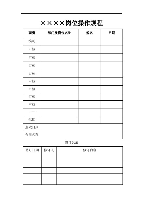
××××岗位操作规程修订记录目录1、总体工艺或设备描述 (4)2、操作参数 (7)3、安全提示及要求 (10)4、开车准备 (15)5、原始开车 (16)6、检修后开车 (19)7、急停后开车 (20)8、正常操作 (21)9、正常停车 (24)10、异常操作 (27)11、紧急停车 (28)12、维修前准备 (30)13、关键控制系统 (32)14、警报及联锁 (33)15、安全设施 (34)16、附件 (35)1、总体工艺或设备描述1。
1工艺原理1。
1.1苯的硝化:酸性苯和混酸以及大量的废酸经泵送入硝化锅进行反应,在其过程中,需控制酸苯与混酸的比例、硝化锅的温度,使反应向着需要的主反应方向进行。
该工艺采用四锅串联反应,为保证反应过程的安全及控制各锅的反应转化率,在硝化锅中加入了大量的废酸,一是便于带出硝化反应过程中大量的生成热,控制硝化锅温度,二是对混酸进行稀释,控制硝化反应的速度,减少二硝及副反应的生成。
H2SO4主反应: C6H6+ HNO3──→C6H5~NO2+ H2O + 134KJ/mol反应机理: HO~NO2+ + H2SO4──→NO2+ + H2O + HSO4~C6H6+NO2+ + HSO4~──→C6H6NO2+ + HSO4~─→C6H5~ NO2+ H2SO4副反应: H2SO4C6H5~NO2+ HONO2──→C6H4~(NO2)2+ H2OH2SO4C6H4HONO2───→C6H5~OH + HNO2C6H5~OH + nHNO3───→ HO~ C6H5~n~(NO2)n + nH2O [n=1~3]1。
1.2中和、脱酚(内容略)1.2流程描述1。
2.1苯的硝化酸性苯从酸性苯贮罐用泵经流量计进入静态混合器中,废酸从废酸高位槽底部经调节阀和流量计也连续进入静态混合器;酸性苯与废酸在混合器中充分混合后,进入1#硝化锅;硫酸、硝酸分别从硫酸罐和硝酸罐用泵经流量计与另一股废酸一起进入三酸混合器混合后也进入1#硝化锅, 酸性苯与混酸在1#硝化锅中反应,反应物料由溢流管进入2#硝化锅,随后进入3#、4#硝化锅继续反应.硝化锅的反应热由冷却水及废酸带走。
DF直读光谱仪操作规程

Procedure1.目的和适用范围Purpose and Application Scope本文件制订了DF 直读光谱仪的操作规程,旨在准确地对钢铁材料进展化学成分定性定量分析。
This document specifiesDF direct reading spectrometer operating procedures, intend to accurately and quantitatively analyze the chemical composition of steel material.2.技术要求Technological requirements2.1运输与移动Transportation& Setting-upDF 系列光谱仪用木制标准包装箱,安装现场可用叉车〔承载力气为400kg〕来移动仪器。
假设要把仪器移动到高于或低于地面的位置,则要用叉车或万能升降车或吊车。
DF series spectrometer is delivered with standard wooden package. Forklift (carrying capacity more than 400 kg) can be used to move this instrument when installation. If the instrument should be moved higher or lower than the location of the ground, then forklift trucks or a general elevator or crane should be used.为修理与保养便利,仪器四周要留有确定空间〔距离墙壁至少0.8m〕。
仪器自身的尺寸是1.42m×1.30m ×0.92m。
此外,还要在仪器四周为打印机、计算机、氩气瓶留出空间,这样工作空间至少需要10m2,与仪器相接的全部接口都位于仪器后面。
燃烧器说明书(新)
FRQ-2DF双燃料燃烧器说明书徐州福尼燃烧控制研究院有限公司二○一○年十月前言_____________________________________________________________________注意感谢您使用徐州福尼燃烧控制研究院有限公司生产的FRQ-2DF型燃烧器。
本手册作为产品完整而必要的一部分提供给用户。
本手册所述内容不仅适用于用户,也可为产品的安装和检修人员提供参考。
关于设备的安装、操作和维护的详细信息,我们建议您仔细阅读。
请妥善保存本手册,以备参考。
_____________________________________________________________________内容介绍:本手册介绍了FRQ-2DF型双燃料燃烧器的结构、特点、安装、操作、维护以及故障处理。
读者对象:本手册适合下列人员阅读:设备安装人员、操作人员、维护人员等。
一、用途及特点FRQ-2DF型系列双燃料燃烧器是徐州福尼燃烧控制研究院有限公司设计开发的节能燃烧设备,它可在工业锅炉、电站锅炉及其它工业窑炉中广泛应用。
FRQ-2DF型双燃料燃烧器能实现助燃风与燃料按比例调节,使燃烧更为稳定可靠,实现全自动运行。
它具有结构紧凑、燃烧稳定、调节比大、噪音低、可内设点火枪和火焰检测报警系统;火焰铺展性好、燃烧完全、燃烧易于控制等特点。
二、主要性能及技术参数1.燃烧器功率:18.5MW/台2.燃烧器调节比:5:13.燃料油参数:油压(枪前油压):1.0~1.2Mpa油枪出力:每台燃烧器1450kg/h雾化方式:蒸汽雾化4.雾化吹扫蒸汽:雾化蒸汽设计流量:300Kg/h雾化蒸汽设计压力(燃烧器前表压):1.0MPa5.燃料气(干气):燃气流量:每台燃烧器2000 Nm3/h燃气气压力(进阀组前):25Kpa燃气温度:常温6.助燃风助燃风温度:常温助燃风压:3500~4500Pa助燃风量:~20000Nm3/h7.点火燃气;点火燃气:干气点火燃气压力:10KPa点火燃气流量:100Nm3/h三、燃烧器及主要配置介绍1.燃烧器燃烧器为双燃料型燃烧器,主要由燃烧器本体、配风器、稳焰装置、燃油喷枪、燃油火检、燃气火检、主气嘴、点火长明灯等组成。
7500说明书

汽车钣金修复机产品使用手册南昌市曙光电器设备厂SG系列车体外形修复机使用说明一、前言本厂生产的汽车外形钣金修复机是汽车外形及砂板修理最快捷、最理想的专用设备。
本产品调节人性化,优质可靠的选择,直观的电压数码显示。
当汽车车体被撞凹或者损坏时,使用本设备及附件,便捷快捷,完美地将凹陷部位和损坏部分修整复原。
三、电源要求由于修复机输入功率在工作时输入电流较大,所以电源的导线应选用较大介面积的铜芯导线(6平方毫米以上)在线路长度超过6米时,导线截面积应相对加大。
四、面板示意图五、随机配置单六、电源要求:1.由于本系列产品在工作时输入瞬间电流较大,所用电源导线要求截面积6平方毫米以上的铜芯线,并注意将机壳接好安全地线。
2.检查电源电压是否与本机后壳上的名牌电压相符,严禁接错。
六、使用操作说明(各型号机使用方法相同)1.车体介子焊接功能(修复凹陷部位);2.打磨漆绣:修复前在作业部位附件,选取一个合适的部位接搭铁线,(即用搭铁线夹、夹住打磨干净部位,并确认与修复位置能良好的通过焊接电流),把搭铁钳夹好。
(如图四)3.在介子焊头装到焊枪黄铜夹头上,把介子放到夹头开口处。
按机器电源标贴要求接通电源,功能选择调到自动档位,然后紧握焊枪,把介子边碰车体,按动操作柄上的微动开关,即完成一次焊接过程。
(注:时间调到0.1-0.2之间,电压档调至适当档位)。
、既时间与电压的调整,用户根据钣金的厚度,探索出的较为理想的经验值,否则会产生火花。
4.拉锤的使用;将拉锤钩住介子,然后握住柄和锤,顺拉捶轴向,将拉锤向车体外撞击,有时需要重复数次,方可将车体凹陷部位的一个范围拉倒原位,如果凹陷面积较大,应焊接多个介子,修复后只要轻轻扭转拉锤即可卸介子(如图)七、单面点焊(车体洞口或局部锈坏修复功能)1.将洞口周围的漆绣彻底打磨干净,取一略大于洞口的铁板做镶补件,铁板的四周两面的漆锈均打磨干净后覆盖在缺口上,作单面焊接。
2.调整‘焊接时间’旋钮(时间调到0.2-0.4之间),电压档位调整开关调到6档,将点焊头插入焊枪内,做点焊作业,压紧铁板边沿,铁板与车体必须紧密结合,按动焊枪开关,带焊接完毕后才松开焊枪,既完成一次焊接过程,铁板四周应均布焊点。
全自分体式煤气燃烧器使用说明书

“JNGJ”型全自动分体式煤气燃烧器安装、使用、维护说明书目录一、技术参数二、燃烧器概述(一)燃烧器主要功能(二)燃烧能力与空、煤气压力的关系(三)空、煤气压力与温度的关系三、燃烧器管道配制示意图(一)配套件功能与说明四、操作说明五、燃烧器的安装与调整六、电器原理图七、燃烧器维护、常见故障与排除方法八、安全建议一、技术参数二、燃烧器概述燃烧器主要由:机头、负荷调节装置、点火阀组、主管道阀组、控制系统、压缩空气、鼓风机等组成。
机头:将空气和煤气充分混合与燃烧,并保持稳定的燃烧效果和出力,为锅炉提供足够的热能,达到生产需求。
负荷调节装置:自动或手动调节燃烧器出力,同步调节煤气和空气流量,达到最佳燃烧效果与机组足够的出力。
点火阀组:提供机头稳定安全的点火热源,保证机头主燃气安全稳定的燃烧。
主管道阀组:自动切断和打开主燃气管道上的气动切断阀,并配有手动切断阀,以保证用气安全,每次启动燃烧器前自动对管道上的两个气动切断阀进行泄漏检测,若发现有阀门泄漏停机并报警那个阀门泄漏,以便针对性的维修,节约维修时间和工作量。
控制系统:自动检测锅炉蒸汽压力,发现蒸汽压力超过极限压力自动停机并报警,发现煤气压力低于设定值或高于设定值自动停机并报警,发现鼓风机压力低于设定值自动停机并报警。
压缩空气系统:提供稳定清净的压缩气源,为气动切断阀提供动力。
鼓风机:为燃烧机组提供足够的助燃空气并保证足够的压力。
外形布置图机头外形图(一)燃烧器主要功能:1.主燃气管道气动切断阀自动检测泄漏,分别对主燃气管道的两个气动切断阀进行泄漏检测,发现有泄漏停机并报警;2.自动吹扫:点火前和停机后自动吹扫炉膛,将未燃尽的煤气用空气吹扫出炉膛,避免发生安全隐患。
3.自动点火:自动点火并检测是否点火成功,若发现点火失败停机并报警,点火成功后打开主燃气管道气动切断阀。
4.实时火焰检测:实时对炉膛内进行火焰检测,发现有火源HMI上的明显提示。
燃烧器运行后若发现火焰熄灭,自动停机并报警。
辽宁赫尔利克电子科技有限公司 MP-5 可燃气体传感器操作手册说明书

Flammable Gas Sensor(Model:MP-5)ManualVersion: 1.3Valid from: 2014-05-01Zhengzhou Winsen Electronics Technology Co., LtdStatementThis manual copyright belongs to Zhengzhou Winsen Electronics Technology Co., LTD. Without the written permission, any part of this manual shall not be copied, translated, stored in database or retrieval system, also can’t spread through electronic, copying, record ways.Thanks for purchasing our product. In order to let customers use it better and reduce the faults caused by misuse, please read the manual carefully and operate it correctly in accordance with the instructions. If users disobey the terms or remove, disassemble, change the components inside of the sensor, we shall not be responsible for the loss.The specific such as color, appearance, sizes &etc, please in kind prevail.We are devoting ourselves to products development and technical innovation, so we reserve the right to improve the products without notice. Please confirm it is the valid version before using this manual. At the same time, users’ comments on optimized using way are welcome.Please keep the manual properly, in order to get help if you have questions during the usage in the future.Zhengzhou Winsen Electronics Technology CO., LTD.Tel: 86-371-67169097 / 67169670 Fax: 86-371-60932988 Email: *******************MP-5 Flammable gas SensorProfileMP-5 gas sensor is for flammable gases. It adopts multilayer thick film manufacturing technology. The heater and metal oxide semiconductor material on the ceramic substrate of subminiature Al 2O 3 are fetched out by electrode down-lead, encapsulated in metal socket and cap. Conductivity of the sensor is affected by the concentration of target gas. The higher the concentration is, the higher conductivity of sensor gets. Users can adopt simple circuit to convert variation of conductivity into output signal corresponding to gas concentration.Features:* Lower consumption * Small size* Fast response and resume * Highest sensitivity* Excellent stability and long life * Easy circuit and big signal output *Excellent selectivityApplicationIt is widely used in domestic gas leakage alarm, industrial flammable gas alarm and portable gas detector.Technical ParametersTel: 86-371-67169097 / 67169670 Fax: 86-371-60932988 Email: *******************Basic circuitInstructions: The above fig is the basic test circuit of MP-5.The sensor requires two voltage inputs: heater voltage (V H ) and circuit voltage (V C ). V H is used to supply standard working temperature to the sensor and it can adopt DC or AC power, while V RL is the voltage of load resistance R L which is in series with sensor. Vc supplies the detect voltage to load resistance R L and it should adopts DC power.Description of Sensor CharactersFig5.Response and ResumeFig6.Linearity curveFig3.Typical Sensitivity Curve The ordinate is resistance ratio of the sensor (Rs/R 0), the abscissa is concentration of gases. Rs means resistance in target gas with different concentration, R 0 means resistance of sensor in clean air . All tests are finished under standard test conditions.Fig4.Typical temperature/humidity characteristicsThe ordinate is resistance ratio of the sensor (Rs/Rso).Rs means resistance of sensor in 2000ppm propane (C 3H 8) under different tem. and humidity. Rso means resistance of the sensor in 2000ppm propane (C 3H 8) under 20℃/65%RH.时间(S) C 3H 8Air CH 4 AlcoholTime (s)Concentration (ppm) Output voltage ( V)Tel: 86-371-67169097 / 67169670 Fax: 86-371-60932988 Email: *******************Long-term StabilityTest is finished in standard test conditions, the abscissa is observing time and the ordinate is V RL .Cautions1 .Following conditions must be prohibited1.1 Exposed to volatilizable organic silicon steamSensing material will lose sensitivity and never recover if the sensor absorbs organic silicon steam. Sensors must be avoided exposing to silicon bond, fixature, silicon latex, putty or plastic contain silicon environment. 1.2 High Corrosive gasIf the sensors are exposed to high concentration corrosive gas (such as H 2S, SO X , Cl 2, HCl etc.), it will not only result in corrosion of sensors structure, also it cause sincere sensitivity attenuation. 1.3 Alkali, Alkali metals salt, halogen pollutionThe sensors performance will be changed badly if sensors be sprayed polluted by alkali metals salt especially brine, or be exposed to halogen such as fluorine.1.4 Touch waterSensitivity of the sensors will be reduced when spattered or dipped in water.1.5 FreezingDo avoid icing on sensor’s surface, otherwise sensing material will be broken and lost sensitivity. 1.6 Applied higher voltageApplied voltage on sensor should not be higher than stipulated value, even if the sensor is not physically damaged or broken, it causes down-line or heater damaged, and bring on sensors’ sensitivity characteristic changed badly. 1.7 Voltage on wrong pinsAs Fig8. Pin 1&2 connects to heater circuit, Pin 3&4 connects to measuring circuit; Under the requested conditions, heating and measuring can use the same power circuit. NOTE: the two pins near the protuberance mark is heating electrode.Time (day)Output voltage ( V)Pin 1&2 is heating electrode,Pin 3&4 is measuring electrode.Protuberance MarkFig8.Pin Schematic Diagram2 .Following conditions should be avoided2.1 Water CondensationIndoor conditions, slight water condensation will influence sensors’ performance lightly. However, if water condensation on sensors surface and keep a certain period, sensors’ sensitiv e will be decreased.2.2 Used in high gas concentrationNo matter the sensor is electrified or not, if it is placed in high gas concentration for long time, sensors characteristic will be affected. If lighter gas sprays the sensor, it will cause extremely damage.2.3 Long time storageThe sensors resistance will drift reversibly if it’s stored for long time without electrify, this drift is related with storage conditions. Sensors should be stored in airproof bag without volatile silicon compound. For the sensors with long time storage but no electrify, they need long galvanical aging time for stability before using. The suggested aging time as follow:Stable2.2.4 Long time exposed to adverse environmentNo matter the sensors electrified or not, if exposed to adverse environment for long time, such as high humidity, high temperature, or high pollution etc., it will influence the sensors’ performance badly.2.5 VibrationContinual vibration will result in sensors down-lead response then break. In transportation or assembling line, pneumatic screwdriver/ultrasonic welding machine can lead this vibration.2.6 ConcussionIf sensors meet strong concussion, it may lead its lead wire disconnected.2.7 Usage Conditions2.7.1For sensor, handmade welding is optimal way. The welding conditions as follow:Tel: 86-371-67169097 / 67169670 Fax: 86-371-60932988 Email: *******************●homothermal soldering iron●Temperature:250℃●Time:less than 3 seconds2.7.2If users choose wave-soldering, the following conditions should be obey:●Soldering flux: Rosin soldering flux contains least chlorine●Speed: 1-2 Meter/ Minute●Warm-up temperature:100±20℃●Welding temperature:250±10℃●One time pass wave crest welding machineIf disobey the above using terms, sensors sensitivity will be reduced.Zhengzhou Winsen Electronics Technology Co., LtdAdd: No.299, Jinsuo Road, National Hi-Tech Zone,Zhengzhou 450001 ChinaTel: +86-371-67169097/67169670Fax: +86-371-60932988E-mail:*******************Website:Tel: 86-371-67169097 / 67169670 Fax: 86-371-60932988 Email: *******************。
X-plore 7300_7500_使用说明书_20100617[1]
![X-plore 7300_7500_使用说明书_20100617[1]](https://img.taocdn.com/s3/m/fae342d6d15abe23482f4d74.png)
充电器的工作周期
- 在镍氢电池完全放电的情况下,充电时间需要 10 到 14 个小时。 - 当镍氢电池连接到已接电源的充电器时,充电开始,红色 LED 指示灯亮起。 - 当镍氢电池充满电后,充电器自动切换到待机状态。 - 在待机状态下,镍氢电池始终保持充满电状态。为此,充电器持续向镍氢电 池发出短脉冲,直到连接断开。 - 在待机状态下,镍氢电池不会过载也不会损坏。
XXXXXX XXXXXX XXXXXX XXXXXX
X X X X
X X X X
X X X X
鼓风式空气 过滤呼吸装置
德尔格 X-plore
7300
德尔格 X-plore
7500
X
X
X
X
X
X
X
X
X
X
X
X
X
X
X
X
X
X
X
X
头面部防护装置 A1: 德尔格 X-plore 短头套 TH2(灰色/橙色) A2: 德尔格 X-plore 长头套 TH2(灰色/橙色) A3: 德尔格 X-plore 长头套 TH3(白色) A4: 德尔格 X-plore 研磨面镜 TH2(PC/AC) A5: 德尔格 X-plore 安全头盔 TH2 A6: 德尔格 X-plore 焊接头盔 TH2 A7: 德尔格 X-plore 4740 半面罩 A8: 德尔格 X-plore 6300/6500 全面罩
警告 表示潜在的危险情况,如果没有采取安全防范措施,可能导致死亡或严重伤害。
小心 表示潜在的危险情况,如果不避免,可能导致人身伤害或财产损失。 也可以用来警告不安全的操作。
设备使用的附加信息。
液化天然气(LNG)运行操作手册
液化天然气(LNG)气化站运行操作手册上海清泰液化天然气有限公司编制二零零五年八月公司简介上海清泰液化天然气有限公司是一家致力于液化天然气(LNG)事业发展、集投资开发与工程建设于一体的专业化公司,伴随着中国LNG产业发展而成长。
公司汇集一批在LNG产业领域里从事理论研究和工程实践的先行者,围绕LNG资源进口、储运、终端利用和技术研发开拓业务,为促进国家能源结构变革、提高能源综合利用效率、保护生态环境而进行着努力和探索。
上海清泰公司奉行“真诚合作、协调发展”的企业精神,不断追求先进的项目管理模式,努力打造清泰品牌。
清泰公司愿与燃气界同行一起努力,共同推动中国LNG产业发展,为LNG 在中国的广泛普及应用作出积极贡献。
联系方式:上海清泰液化天然气有限公司公司地址:上海浦建路145号强生大厦1602室联系电话:021-********,50899291传真号码:021—50899293液化天然气(LNG)气化站运行操作手册目录公司简介 0目录 (1)第一章天然气与液化天然气(LNG)知识 (4)1.1 天然气知识 (4)1.1。
1 天然气组成 (4)1。
1.2 天然气燃烧特性 (5)1。
1.3 天然气的储运 (6)1。
2 LNG基本性质 (8)1。
2.1 LNG组分 (8)1.2。
2 LNG物性数据 (9)1.2.3 LNG特点 (9)第二章LNG气化站工艺介绍 (11)2.1 气化站工艺流程 (11)2。
1。
1卸车工艺 (12)2。
1。
2 贮存增压工艺 (12)2。
1。
3 气化加热工艺 (13)2。
1。
4 BOG处理工艺 (13)2.1.5 安全泄放工艺 (14)2。
1.6 计量加臭工艺 (14)2。
2 气化站布置 (15)2.3 LNG气化站主要设备 (15)2.3。
1 LNG储罐 (15)2.3.2 空浴式气化器 (16)2.3.3 水浴式加热器 (16)2.3。
4 缓冲罐 (16)2.3.5 加臭装置 (17)2。
DFB系列燃气燃油平焰燃烧器使用说明书
DFB系列燃气燃油平焰燃烧器使用说明书一、简介球焰燃烧器是近代发展起来的一种新型燃烧装置。
其通过改变配燃空气的流动方式,可方便地调整火焰的形状,从薄层圆盘形变至球形,以适应各种不同的加温工艺和加温阶段。
经过近几年的实践,证明球焰燃烧器是一种非常理想的工业炉燃烧装置。
球焰燃烧器与传统的直焰和平焰燃烧器不同,它的火焰可从圆盘形的薄层火焰变至圆球形火焰。
它采用了两路配气结构,其中一路与燃气有相同的旋向,利用旋转气流的离心作用,使气流沿一个喇叭形的扩张口旋转展开,形成圆盘形的薄层火焰。
另一路配燃空气沿燃烧器自身的轴线向前喷出,与旋转的燃气相混合形成圆球状火焰。
通过改变这两路空气的流量比例,可以有效地改变配燃空气与燃气的掺混程度和混合气流的形状,从而有效地改变燃烧器出口处的火焰形状。
DFB系列球焰燃烧器带有一个设计独特的并联空气调节阀,它在改变一路空气流量的同时能使另一路空气的流量做相应的改变,其结果是维持两路空气流量的总和不变。
这样DFB系列球焰燃烧器比通常的球焰燃烧器具有更大的调节范围,它可以通过完全关闭一路空气而使配燃空气处于全旋或完全不旋的极端状态。
DFB系列球焰燃烧器采用了独特的特定曲线型气流展开口的烧嘴砖,使展平的气流更加均匀稳定,附壁效应更好,可与产生形状更好、温度更高的火焰,取得更好的节能降污效果。
DFB系列球焰燃烧器的特点总结:●采用独特设计的展开曲线,气流展开形状更好,附壁效果更佳●相匹配的燃料喷嘴设计,火焰形状均匀稳定,并可调整●燃烧充分,火焰温度高●可以使用各种燃气作为燃料●结构简单,维修和操作方便●调节范围很宽,对燃料和空气的压力变化有很强的适应性●污染小,烟气中NOx含量低二、DFB系列球焰燃烧器的结构和工作原理1.结构示意图DFB系列球焰燃气燃烧器的结构示意图如图1所示。
2.工作原理DFB系列球焰燃气燃烧器将配燃空气分为两路引至燃烧器出口。
其中一路采用偏心进气以造成空气的强旋流,通过独特设计的曲线形扩张通道,气流被展开成圆盘形的附壁良好的薄层。
洁净天然气燃料换用天然气转换器说明书
INSTALLATION INSTRUCTIONSFor Natural Gas to Propane Conversion Kit Model No:NAHA003LP or Part No.(1174906)This kit is designed to convert the 95%*9UHX Series A and later Gas Furnaces equipped with Single Stage Honeywell VR8205S gas valve.*Denotes Brand (T,H or C)This conversion kit shall be installed by a qualified service agency.Please read these instructions completely before attempting installation.Consult gas supplier and tables in National Fuel Gas Code NFPA 54/ANSI Z223.1,2006or latest edition.In Canada,the National Standard CAN/CGA B149--1and B149--2.Parts ListDescriptionPart#Qty.Burner Orifice #5510113546Honeywell Conv.Kit #39622111729531Switch,Low Pressure(LGPS)10088011Fitting Asy.10097751Wire Asy.11730711Label,Field Conversion 10096781Label,LP Conversion 11729561Label,Derate 25052351Instructions441061075001Orifices for High Altitude Conversion (Not included in kit)(Refer to NO TAG --for required orifice)Burner Orifice #561011355as requiredGeneral InformationThis kit is for conversion of furnaces equipped with Honeywell VR8205S Series single stage gas valves certified for use with Nat-ural Gas(and so marked)to units functionally the same as the cer-tified furnace for use with Propane Gas.Before the furnace can be operated with LP Gas,the low pressure switch must be installed.A gas valve conversion kit must be installed and main burner orifices must be replaced with orifices in this kit or with properly sized ori-fices for high altitude(ordered separately).The orifices provided in this kit are stamped to indicate the size (twist drill number)and are sized for commercially pure propane gas ONLY.DO NOT use them with butane or a mixture of butane and propane gas.The parts list specifies the size orifices supplied in the pare the size marking on the orifices with the sizes as listed in the parts list.Make sure you have the correct main burner orifices.Extreme care is used to assure that this kit contains the proper orifi-ces.Oversized orifices could result in hazardous conditions, especially if the venting is inadequate.For that reason,we rec-ommend that the installer check the size of the orifice with a new twist drill of the correct size.This procedure assures that the ori-fices provided are the correct size.InstallationDisassemblyRefer to Figure1and the following steps.1.After disconnecting power and gas supply to the furnace,re-move the access door,exposing gas valve and burner compartment.2.Disconnect gas line from gas valve so manifold assemblycan be removed.3.Disconnect wiring at gas valve.Be sure to note the properlocationof any and all electrical wiring disconnected.4.Remove the four(4)screws holding the manifold and gasvalve to the manifold supports.Do not discard any screws.5.Carefully remove the manifold assembly.Main Burner Orifices1.Remove the Naturalgas(typically black)burner orifices from the manifold assembly and replace them with the ap-propriate Propane(silver)orifices furnished in the conver-sion kit unless converting a high altitude unit,then see Table1for appropriate orifices.(Figure2)2.T ighten the orifices so they are seated and gas tight about11/8″from the face of the orifice to the back of the manifold pipe(Figure3).Make sure orifice is installed straight so thatit forms a right angle(90°)to the manifold.High Altitude InstallationGas input rate on the furnace rating plate is for installation at up to 2000′.The #55burner orifices supplied in this kit are sized for Pro-pane Gas at full rate ONLY ,for use between 0--2000′elevation.Do not use them above 2000′(except when noted by Table 1).Ori-fices for conversion at high altitude must be ordered from Service Parts.In the USA,the input rating for altitudes above 2000′must be de--rated by 4%for each 1000′above sea level (see Table 1).In Canada,the input rating for altitudes above 2000′must be re-duced by 10%for altitudes of 2000′to 4500′above sea e the 2001to 3000column in Table 1.MANIFOLD PRESSURE AND ORIFICE SIZETable 1LPG or PROPANE GAS MANIFOLD PRESSURE (″w.c.)HEATING VALUE at ALTITUDE BTU/CU.FT .MEAN ELEVATION FEET ABOVE SEA LEVEL 0to 20002001to 30003001to 40004001to 50005001to 60006001to70007001to 8000250010.08.98.410.0101010.0Orifice Size#55#55#55#56#56#56#56NOTE:Propane data is based on 1.53specific gravity.For fuels with different specific gravity consult the National Fuel Gas Code ANSI Z223.1--2006/NFPA54--2006or National Standard Of Canada,Natural Gas And Propane Installation Code CSA B149.1--05.NOTE:In the USA,the input rating for altitudes above 2000′must be derated by 4%for each 1000′above sea level (see Table 1)In Canada,the input rating for altitudes above 2000′must be reduced by 10%for altitudes of 2000′to 4500′above sea e the 2001to 3000column in Table 1.Gas Valve ConversionConversion of Honeywell VR8205S Gas Valve using Propane Gas Conversion Kit #396221.1.Remove the cap screw and pressure regulator adjusting screw.(See Figure 5or Figure 6)2.Remove the existing regulator spring from the regulator housing.3.Insert the replacement spring (red color)contained in this kit into regulator housing.4.Install the pressure regulator adjusting screw and give it eleven (11)full clockwise turns.This will set the manifold pressure close to required setting for normal operation.5.Replace the regulator cap screw.6.Attach the Yellow Attention Label contained in the kit to the Gas Valve where it can be readily seen.LP Low Pressure Switch(Required)ing pipe joint compound that is resistant to LP gas,tightenthe fitting assembly into the inlet side of the gas valve.(Figure8).Position fitting assembly as shown.2.Screw the LP pressure switch into the e pipedope on connection.Tighten securely.Note:Do not block inlet port of pressure switch with pipe dope. Switch will not operate if inlet port is blocked.3.Remove one yellow wire from the air pressure switch.Connect this wire to the male terminal of the insulated yellow wire in the wire harness provided.4.Connect the other yellow wire in the harness to the opentermination on the air pressure switch.5.Connect the other end of the wire harness to the two termi-nals on the LP switch.Note:LP switch is factory set to open if LP gas supply pressure falls below6″w.c.Note:See Furnace Wiring Label,to confirm wiring. ReassemblyReassemble all parts in reverse order as removed.Attach LP Conversion Label next to the furnace rating plate or to the front exterior of the furnace.•Manifold Assembly--Be sure to engage the main burner orifices in the proper openings in the burners.•Verify the ignitor is in the correct location.(See Figure4)•Testing for leaks--After reassembly,turn the gas on and check all joints for gas leaks using a soapy solution.All leaks must be repaired immediately.Gas Pressure•Refer to the furnace rating plate for the approved gas input rating.•Gas input to burners MUST NOT exceed the rated input shown on rating plate.•Do NOT allow minimum gas supply pressure to vary down-ward.Doing so will decrease input to furnace.Refer to Table2for gas supply and manifold pressures.Table2Gas PressuresGasTypeSupply Pressure ManifoldPressure Recommended Max.Min.LP11″(2.7kPa)14″(3.5kPa)11″(2.7kPa)10″*(2.5kPa)*See Table1Important Notes•With Propane gas,the rated input is obtained when the BTU content is2,500BTU per cubic foot and manifold pressureset at10″W.C.•If Propane gas has a different BTU content,orifices MUST be changed by licensed Propane installer.•Measured input can NOT exceed rated input.•Any major change in gas flow requires changing burner orifice size.Start--up and Check--out1.Remove the plug from the Inlet Pressure Tap on gas valveand install a manometer.(Figure5)2.Open manual gas line valve to unit.Check for gas leaks andcorrect as necessary.Check supply pressure,11″WC rec-ommended,(11″wc minimum,14″maximum).If not within these limitations DO NOT OPERATE FURNACE,contact gas supplier.3.Close manual gas line valve to unit,remove manometer andreplace inlet pressure tap plug.Gas Valve Adjustment1.With the gas valve knob or switch in the OFF position,re-move the pressure tap plug from the outlet end of the valve, and connect a“U”tube manometer to the pressure port.(See Figure5)2.Turn the gas valve knob or switch to the ON position and re-store electrical power to unit.Cycle the main burner on and off several times to stabilize the pressure regulator diaph-ragm.This MUST be done before an accurate pressure reading can be obtained.3.With the main burner on,read the manometer.For appropri-ate reading see Table1.Turn pressure regulator adjusting screw clockwise to increase or counterclockwise to de-crease manifold pressure.Burner Input must not exceed nameplate rating.Refer to Section“Checking Input Rate”.4.Turn gas valve to OFF.Remove the manometer and replacethe pressure tap plug and pressure regulator cap screw.5..Start the main burners and check pressure tap plug for gasleaks.6.With gas valve on,observe furnace through two or morecomplete cycles to be sure all controls are operating. Checking Input Rate*High Altitude Input Rate=Nameplate Sea Level Input Rate x(Multiplier)Elevation High Altitude Multiplier LP Gas*0′-2000′ 1.002001′-3000′0.903001′-4000′0.864001′-5000′0.825001′-6000′0.786001′-7000′0.747001′-8000′0.70 *Based on mid--range of elevation.Main Burner Flame CheckCheck for the following:(See Figure7)•Stable and blue flames.Dust may cause orange tips or wisps of yellow,but flames MUST NOT have solid,yellow tips.•Flames extending directly from burner into heat exchanger.•Flames do NOT touch sides of heat exchangerIf any problems with main burner flames are noted,it may be nec-essary to adjust gas pressures or check for drafts.High Altitude Derated Unit LabelThe derated label supplied with the conversion kit must be com-pleted and affixed to the furnace near the rating plate.Fill in the manifold pressure,orifice size and revised input rate.Refer to Table1provided to determine the proper orifice part num-bers for ordering purposes.Verify System OperationUpon completion of all conversion procedures,perform the follow-ing steps to attach the appropriate labels and verify the system operation.1.Locate the LP Conversion Label next to the furnace ratingplate.2.Fill out and attach the Field Conversion Label near the fur-nace rating plate or to the front exterior of the furnace. 3.Turn the thermostat to its lowest temperature setting or toOFF if equipped with a System Select Switch.4.Turn the gas valve control knob or switch to ON.5.Reinstall all access panels.6.Turn ON all electrical power to the unit.7.Set the thermostat to the desired temperature and theSystem Select Switch to HEAT.8.Observe unit operation through two(2)complete heatingcycles.See“Sequence of Operation”in furnace installation instructions.。
可燃气体报警系统操作及维护保养规程(NV-500 控制器,KD-5B 探测器)

可燃气体报警系统操作及维护保养规程(NV-500 控制器,KD-5B 探测器)41.1 简要说明新宇宙可燃气体检测报警系统由 NV-500 型气体报警控制器和 KD-5B 型可燃气体探测器 组成,每个检测单元由一个 N V-500 控制模块和 K D-5B 探测器组成。
探测器负责实时检测现场可燃气体浓度,并将气体浓度信息通触点信号实时传送至控制器进行集中监控管理。
当现场气体浓度超过预设的报警值时,探测器通过数字显示屏显示现场气体浓度,并发 出声光报警信号,控制器通过显示屏数字显示气体浓度和 LED 闪烁光指示报警状态,并发出区域声光报警信息。
控制器与探测器之间通过三芯屏蔽电缆连接。
41.2 产品规格及接线41.2.1 规格类别规格参数 标准控制器 输入电压 220 VAC, 50Hz 工作电压220 VAC, 50Hz 输出信号 继电器开关量 显示方式 条状码显示 报警方式声光报警探测器工作电压 24 VDC (由控制器供给) 报警方式通过控制器报警41.2.2 电气接线图图 1图 241.2.3 系统接线图图 241.2.4 探测器接线图图 341.3 功能描述新宇宙可燃气体检测报警系统,由 N V-500 型气体报警控制器(以下简称控制器)和 K D-5B 型可燃气体探测器(以下简称探测器)组成,用于对被测场所的可燃气体浓度进行有效的检 测、显示、报警与控制。
控制器由一个标准的 1-12 通道壁挂式机箱和 1~12 组控制模块组成,可分别挂接 1~12 台KD-5B 型探测器。
控制器与探测器之间采用一一对应的独立通道通讯方式,每通道控制器都可独立显示、独立报警和独立输出。
每通道设有二段报警点设置功能,可发出二段不同的闪烁光报警信号和区域声光报警信号,并输出 2 段报警无源开关量信号(触点容量 3A/24VDC)。
探测器可实时检测现场可燃气体浓度,当现场气体浓度超过预设的报警值时,可通过显示屏数字显示现场气体浓度,并发出声光报警信号,并将气体浓度信息通过1-5mV 信号实时传送给控制器。
湖南三德科技热值分析系列产品说明书

官方微信官方网站目 录SDAC6000(u)量热仪SDACM4000量热仪SDACM3100量热仪SDC712量热仪SDC715量热仪01-05热值分析系列020*********-11元素分析系列SDCHN536碳氢氮元素分析仪SDCH536红外碳氢仪SDH536红外测氢仪SDS350红外定硫仪SDS820自动定硫仪SDS720自动定硫仪SDS-V 定硫仪SDFCl3000自动氟氯分析仪SDFCl1000(a)氟氯分析仪070707080909101111SDTGA8000(a)工业分析仪SDTGA6000工业分析仪SDTGA6000A 工业分析仪SDTGA6000V 工业分析仪SDTGA5000a 工业分析仪SDTGA520(a)水分测试仪SDTGA500光波水分测试仪SDIMF200智能马弗炉SDMF300马弗炉SDIDB413智能干燥箱SDDH315通氮鼓风干燥箱SDDH323鼓风干燥箱SDDH313鼓风干燥箱SDDH306鼓风干燥箱12-22成分分析系列1314151516171819202121222222SDAF105(a /b )灰熔融性测试仪SDAF4000灰熔融性测试仪SDHG60a 哈氏可磨性指数测定仪23-26物理特性分析系列242526S DUC3150(D )联合制样机S DHD150t 锤式破碎缩分机S DHC锤式破碎机S DJC颚式破碎机S DRC对辊破碎机S DHCW400×260湿煤破碎机S DPP制样粉碎机S DMD16自动机械缩分器S DNS300环保振筛机S DNS200a标准振筛机S DRD二分器采制样辅助工具30-38样品制备系列313232333334343535353637-38激光盘料仪系列SDLM200便携式激光盘料仪SDLM1250固定式激光盘料仪39-41404142-43公司简介44发展历程45运维服务2829S DVD25风透 式快速除湿干燥系统S DVD3mm 风透 干燥机27-29风透 式低温快速除湿干燥系列热值分析系列适用范围符合标准GB/T213-2008GB/T384-1981 GB/T30727-2014ASTM D5865-2007ISO 1928-2009 JC/T1005-2006《煤的发热量测定方法》《石油产品热值测定法》《固体生物质燃料发热量测定方法》《煤与焦炭总热值的标准试验方法》《固体矿物燃料-氧弹式量热计测定总值并计算净热值》《水泥黑生料发热量测定方法》三德科技是中国第一台自动量热仪(1996年)的发明者,先后自主研发出6代量热仪,缔造了2个“国家重点新产品”。
