注塑模具外英文翻译
模具术语英文翻译

模具术语英文翻译三、模具塑料模具mould of plastics注塑模具injection mould冲压模具die模架mould base定模座板Top clamping plate Top plateFixed clamp plate水口推板stripper plateA板A plateB板B plate支承板support plate方铁spacer plate底针板ejector plate面针板ejector retainer plate回针Return pin导柱Guide pin有托导套Shoulder Guide bush 直导套Straight Guide bush动模座板Bottom clamp plate Moving clamp plate基准线datum line基准面datum plan型芯固定板core-retainer plate 凸模固定板punch-retainer plate 顶针ejector pin单腔模具single cavity mould多腔模具multi-cavity mould多浇口multi-gating浇口gate缺料starving排气breathing光泽gloss合模力mould clamping force锁模力mould locking force挤出extrusion开裂crack循环时间cycle time老化aging螺杆screw麻点pit嵌件insert活动镶件movable insert起垩chalking浇注系统feed system主流道sprue分流道runner浇口gate直浇口direct gate , sprue gate轮辐浇口spoke gate , spider gate点浇口pin-point gate测浇口edge gate潜伏浇口submarine gate , tunnel gate 料穴cold-slug well浇口套sprue bush流道板runner plate排飞槽vent分型线(面)parting line定模stationary mould,Fixed mould 动模movable mould, movable half上模upper mould,upper half下模lower mould,lower half型腔cavity凹模cavity plate,cavity block拼块split定位销dowel定位销孔dowel hole型芯core斜销angle pin, finger cam滑块slide滑块导板slide guide strip楔紧块heel block, wedge lock拉料杆sprue puller定位环locating ring冷却通cooling channel脱模斜度draft滑动型芯slide core螺纹型芯threaded core热流道模具hot-runner mould绝热流道模insulated runner mould熔合纹weld line (flow line)三板式模具three plate mould脱模ejection换模腔模具interchangeable cavity mould 脱模剂release agent注射能力shot capacity注射速率injection rate注射压力injection pressure差色剂colorant保压时间holdup time闭模时间closing time定型装置sizing system阴模female mould,cavity block阳模male mould电加工设备Electron Discharge Machining数控加工中心CNC machine center万能铁床Universal milling machine卧式刨床Horizontal planer车床Engine lathe平面磨床Surface grinding machine去磁机Demagnetization machine万能摇臂钻床Universal radial movable driller 立式钻床Vertical driller超声波清洗机Ultrasonic clearing machine。
(精编)模具注塑术语中英文对照
(精编)模具注塑术语中英文对照(精编)模具注塑术语中英文对照根据国家标准,以下为部分塑料模具成形术语的标准翻译。
动模MovableMouldMovingHalf定模座板FixedClampPlateTopClampingPlateTopPlate动模座板MovingClampPlateBottomClampingPlateBottomPlate上模座板UpperClampingPlate下模座板LowerClampingPlate凹模固定板Cavity-retainerPlate 型芯固定板MouldCore-retainerPlate凸模固定板Punch-retainerPlate模套DieBodyDieSleeveDieBlank支承板BackingPlateSupportPlate垫块SpacerParallel支架EjectorHousingMouldBaseLeg模头DieHead模具分类8InjectionMold注塑模PlasticRubberMould塑胶模RubberMolding橡胶成形HotChamberDieCasting热室压铸SandMoldCasting砂模铸造ExtrusionMold挤出模Multi-CavityMold多模穴模具PalletizingDie叠层模PlasterMold石膏模ThreePlatesMold三板模PlainDie简易模PierceDie冲孔模FormingDie成型模ProgressiveDie连续模GangDies复合模ShearingDie剪边模CavityDie型腔模RivetingDie铆合模CompressionMolding压缩成型FlashMold溢流式模具ExtrusionMold挤压式模具SplitMold分割式模具MouldCavity型腔母模MoldCore模芯公模LargeDieMold大型模具PreciseDieMold 精密模具ComplexDieMold复杂模具FoamingMould发泡模具MetalDie金属模具PlasticMold塑料模具ToolStampingDiePunchDie冲压模具ExtrusionDie挤压模具GraphiteDie石墨模具流道浇口部分RunnerSystem浇道系统SprueColdMaterialTrap浇道冷料井SpruePuller拉杆RunnerDesign流道设计MainRunner主流道SecondaryRunner 次流道MouldGateDesign浇口设计SubmarineGate潜伏浇口TunnelGate隧道式浇口PinpointGate点浇口FanGate扇形浇口SideGate侧浇口EdgeGate侧缘浇口TabGate 搭接浇口FilmGate薄膜浇口FlashGate闸门浇口SlitGate缝隙浇口DishGate盘形浇口DiaphragmGate隔膜浇口RingGate环形浇口Runnerless无浇道Sprueless无射料管方式LongNozzle延长喷嘴方式Sprue浇口,溶渣Insulated/HotRunner热浇道RunnerPlat 浇道模块ValveGate阀门浇口SlagWell冷料井ColdSlag冷料渣SprueGate射料浇口Nozzle 射嘴SprueLockPin料头钩销(拉料杆)注塑缺陷Flash飞边Warpage翘曲AirTrap积风Blush发赤FlowLine流痕Splay银纹ShortShot 短射SinkMark缩痕Streak条纹Void缩孔WeldLine熔接线GasMark烧焦ColdSlug冷斑Delamination起皮Burr毛刺FlawScratch刮伤Gloss光泽Glazing光滑SurfaceCheck表面裂痕Hesitation迟滞注塑工艺MoldingConditions成型条件Drying烘干BarrelTemperature 料筒温度MeltTemperature熔化温度MoldTemperature模具温度InjectionPressure注塑压力BackPressure背压InjectionSpeed注塑速度ScrewSpeed螺杆转速TensileStrength抗拉强度T ensileElongation延伸率FlexuralModulus弯曲模FlexuralStrength抗弯强度Shrinkage收缩率RegrindUsage次料使用Moulding模塑机械设备Lathe车床Planer刨床Miller/MillingMachine铣床Grinder磨床Driller钻床LinearCutting线切割ElectricalSparkle电火花Welder电焊机PunchingMachine冲床Robot机械手CommonEquipment 常用设备EDMElectronDischargeMachining放电加工3DCoordinateMeasurement三次元量床BoringMachine搪孔机ContouringMachine轮廓锯床CopyGrindingMachine仿形磨床CylindricalGrindingMachine外圆磨床DieSpottingMachine合模机EngravingMachine 雕刻机EngravingE.D.M雕模放置加工机FormGrindingMachine成形磨床GraphiteMachine石墨加工机HorizontalBoringMachine卧式搪孔机HorizontalMachineCenter卧式加工制造中心InternalCylindricalMachine内圆磨床模具零件TopPlate上托板(顶板)T opBlock上垫脚PunchSet上模座PunchPad上垫板PunchHolder上夹板StripperPad脱料背板UpStripper上脱料板MaleDie公模(凸模)FeatureDie公母模FemaleDie母模(凹模)UpperMoldPlate上模板LowerMoldPlate 下模板DiePad下垫板DieHolder下夹板DieSet下模座BottomBlock下垫脚BottomPlate下托板(底板)StrippingPlate内外打(脱料板)OuterStripper外脱料板InnerStripper内脱料板LowerStripper下脱料板InnerGuidingPost 内导柱InnerHexagonScrew内六角螺钉DowelPin固定销MouldCoilSpring模具弹簧LifterPin 顶料销IsoheightSleeve等高套筒Pin销LifterGuidePin浮升导料销GuidePin导正销WireSpring圆线弹簧OuterGuidingPost外导柱StopScrew止付螺丝LocatedPin定位销OuterBush外导套Punch冲头Insert入块(嵌入件)DeburringPunch压毛边冲子GroovePunch压线冲子StampedPunch字模冲子RoundPunch圆冲子SpecialShapePunch 异形冲子BendingBlock折刀Roller滚轴BafflePlate挡块LocatedBlock定位块SupportingBlockforLocation定位支承块AirCushionPlate气垫板Air-CushionEject-rod 气垫顶杆TrimmingPunch切边冲子StiffeningRibPunchStinger加强筋冲子RibbonPunch压筋冲子Reel-stretchPunch卷圆压平冲子GuidePlate定位板SlidingBlock滑块SlidingDowelBlock滑块固定块ActivePlate活动板LowerSlidingPlate 下滑块板UpperHolderBlock上压块UpperMidPlate上中间板SpringBox弹簧箱Spring-BoxEject-rod弹簧箱顶杆Spring-BoxEjec模具技术用语各种常用模具成形方式AccurateDieCasting精密压铸PowderForming粉末成形CalendaringMolding压延成形PowderMetalForging粉末锻造ColdChamberDieCasting冷式压铸PrecisionForging 精密锻造ColdForging冷锻PressForgingstampforging冲锻CompactingMolding粉末压出成形RockingDieForging摇动锻造CompoundMolding复合成形RotaryForging回转锻造CompressionMolding压缩成形RotationalMolding离心成形DipMold浸渍成形RubberMolding橡胶成形EncapsulationMolding注入成形SandMoldCasting砂模铸造ExtrusionMolding挤出成形ShellCasting壳模铸造FoamForming 发泡成形SinterForging烧结锻造ForgingRoll轧锻SixSidesForging 六面锻造GravityCasting重力铸造SlushMolding凝塑成形HollowBlowMolding中空(吹出)成形SqueezeCasting高压铸造HotChamberDieCasting热室压铸Swaging挤锻HotForging 热锻TransferMolding转送成形InjectionMolding射出成形WarmForging温锻InvestmentCasting精密铸造MatchedDieMethod对模成形法LaminatingMethod被覆淋膜成形LowPressureCasting低压铸造LostWaxCasting脱蜡铸造MatchedMouldThermalForming对模热成形模CloseMold合模Demould脱模脱模剂MouldUnloading开模ToolChangeRetoolingDieChanging换模MouldClamping锁模各式模具分类用语BismuthMold铋铸模LandedPlungerMold有肩柱塞式模具BurnishingDie挤光模LandedPositiveMold有肩全压式模具ButtonDie镶入式圆形凹模LoadingShoeMold料套式模具Center-GatedMold中心浇口式模具LooseDetailMold活零件模具ChillMold冷硬用铸模LooseMold活动式模具ColdHobbing冷挤压制模法LouveringDie百叶窗冲切模CompositeDies复合模具ManifoldDie分歧管模具CounterPunch反凸模ModularMold组合模具DoubleStackMold双层模具Multi-CavityMold多模穴模具ElectroformedMold电铸成形模Multi-GateMold复式浇口模具ExpanderDie扩径模OffsetColdBendingDie双折冷弯模具ExtrusionDie挤出模PalletizingDie叠层模FamilyMold反套制品模具PlasterMold石膏模BlankThroughDies漏件式落料模PorousMold通气性模具DuplicatedCavityPlate复板模PositiveMold全压式模具FantailDie扇尾形模具PressureDie压紧模FishtailDie鱼尾形模具ProfileDie轮廓模FlashMold溢料式模具ProgressiveDie顺序模GypsumMold石膏铸模PortableMold手提式模具Hot-RunnerMold热流道模具PrototypeMold雏形试验模具原型模具IngotMold钢锭模PunchingDie落料模LancingDie切口模切缝模Raising(Embossing)压花起伏成形Re-entrantMold倒角式模具SectionalDie拼合模RunlessInjectionMold无流道冷料模具SectionalDie对合模具SegmentMold组合模Semi-PositiveMold半全压式模具Shaper 定型模套SingleCavityMold单腔模具SolidForgingDie整体锻模SplitForgingDie拼合锻模SplitMold双并式模具SpruelessMold无注道残料模具SqueezingDie挤压模StretchFormDie拉伸成形模SweepingMold 平刮铸模SwingDie振动模具ThreePlatesMold三片式模具TrimmingDie切边模UnitMold单元式模具UniversalMold 通用模具UnscrewingMold退扣式模具YokeTypeDie轭型模t-Plate弹簧箱顶板BushingBlockLinerBushing衬套CoverPlate盖板GuidePad导料块模具厂常用之标准零配件AirVentValve通气阀AnchorPin锚梢AngularPin角梢Baffle调节阻板AngularPin倾斜梢BafflePlate折流档板BallButton球塞套BallPlunger定位球塞BallSlider球塞滑块BinderPlate压板BlankHolder防皱压板BlankingDie落料冲头Bolster上下模板Bottomboard浇注底板Bolster垫板BottomPlate下固定板Bracket托架BumperBlock 缓冲块Buster堵口CastingLadle浇注包Castinglug铸耳Cavity模穴(模仁)CavityRetainerPlate模穴托板CenterPin中心梢ClampingBlock 锁定块CoilSpring螺旋弹簧ColdPunchedNut冷冲螺母CoolingSpiral螺旋冷却栓Core心型CorePin心型梢Cotter开口梢Cross十字接头CushionPin缓冲梢DiaphragmGate盘形浇口DieApproach模头料道DieBed型底DieBlock块形模体DieBody铸模座DieBush合模衬套DieButton冲模母模DieClamper夹模器DieFastener模具固定用零DieHolder母模固定板DieLip模唇DiePlate冲模板DieSet冲压模座DirectGate直接浇口DogChuck爪牙夹头Dowel定位梢DowelHole导套孔DowelPin合模梢Dozzle辅助浇口DowelPin定位梢Draft拔模锥度DrawBead张力调整杆DriveBearing传动轴承EjectionPad顶出衬垫Ejector脱模器EjectorGuidePin顶出导梢EjectorLeaderBush顶出导梢衬套EjectorPad顶出垫EjectorPin 顶出梢EjectorPlate顶出板EjectorRod顶出杆EjectorSleeve顶出衬套EjectorValve顶出阀EyeBolt环首螺栓FillingCore填充型芯椿入蕊FilmGate薄膜形浇口FingerPin指形梢FinishMachinedPlate 角形模板FinishMachinedRoundPlate圆形模板FixedBolsterPlate固定侧模板FlangedPin带凸缘针FlashGate毛边形浇口Flask上箱FloatingPunch浮动冲头Gate浇口GateLand浇口面Gib凹形拉紧楔GooseNeck鹅颈管GuideBushing引导衬套GuidePin导梢GuidePost 引导柱GuidePlate导板GuideRail导轨HeadPunch顶头冲孔HeadlessPunch直柄冲头HeavilyT aperedSolid整体模蕊盒HoseNippler管接头ImpactDamper缓冲器InjectionRam压射柱InlayBush嵌入衬套InnerPlunger内柱塞InnerPunch内冲头Insert 嵌件InsertPin嵌件梢KingPin转向梢KingPinBush主梢衬套KnockoutBar脱模杵Land 合模平坦面LandArea合模面LeaderBush导梢衬套LiftingPin起模顶针起模杆Lining内衬LocatingCenterPunch定位中心冲头LocatingPilotPin定位导梢LocatingRing定位环LockBlock压块LockingBlock定位块LockingPlate定位板LooseBush活动衬套MakingDie打印冲子ManifoldBlock歧管档块MasterPlate靠模样板MatchPlate分型板MoldBase塑胶模座MoldClamp铸模紧固夹MoldPlaten模用板MovingBolster换模保持装置MovingBolsterPlate可动侧模板OnePieceCasting整体铸件ParallelBlock平行垫块PartingLine 分模线PartingLockSet合模定位器PassGuide穴型导板PeenedHeadPunch镶入式冲头锤击强化冲头钻杆凸模PilotPin定位销导向销子PinGate针尖浇口Plate衬板PreExtrusionPunch顶挤冲头Punch冲头Puncher推杆PusherPin衬套梢Rack机架RappingRod起模杆Re-entrantMold凹入模RetainerPin嵌件梢RetainerPlate托料板ReturnPin回位梢RidingStripper浮动脱模器RingGate环型浇口Roller滚筒Runner流道RunnerEjectorSet流道顶出器RunnerLockPin流道拉梢ScrewPlug头塞SetScrew固定螺丝Shedder脱模装置Shim分隔片Shoe模座之上下模板Shoot流道ShoulderBolt肩部螺丝Skeleton骨架SlagRiser冒渣口Slide(SlideCore)滑块SlipJoint滑配接头SpacerBlock间隔块SpacerRing间隔环Spider模蕊支架Spindle主轴Sprue注道SprueBushing注道衬套SprueBushingGuide注道导套SprueLockBushing注道定位衬套SpruePuller注道拉料浇道推出杆注道残料顶销SpewLine合模线SquareKey方键SquareNut方螺帽SquareThread方螺纹LimitStopCollar限位套StopPin止动梢StopRing止动环Stopper定位停止梢StraightPin圆柱销StripperBolt脱料螺栓StripperBushing脱模衬套StripperPlate剥料板StrokeEndBlock行程止梢SubmarineGate潜入式浇口SupportPillar支撑支柱顶出支柱SupportPin支撑梢SupportingPlate托板SweepT emplate造模刮板TabGate辅助浇口TaperKey推拔键TaperPin拔锥梢锥形梢TeemingPouring浇注ThreeStartScrew 三条螺纹ThrustPin推力销TieBar拉杵TunnelGate隧道形浇口Vent通气孔WortlePlate拉丝模板模具常用之工作机械3DCoordinateMeasurement三次元量床BoringMachine搪孔机CNCMillingMachineCNC铣床ContouringMachine轮廓锯床CopyGrindingMachine仿形磨床CopyLathe仿形车床CopyMillingMachine仿形铣床CopyShapingMachine仿形刨床CylindricalGrindingMachine外圆磨床DieSpottingMachine合模机DrillingMachine钻孔机EngravingMachine雕刻机EngravingE.D.M 雕模放置加工机FormGrindingMachine成形磨床GraphiteMachine 石墨加工机HorizontalBoringMachine卧式搪孔机HorizontalMachineCenter卧式加工制造中心InternalCylindricalMachine内圆磨床JigBoringMachine冶具搪孔机JigGrindingMachine冶具磨床LapMachine研磨机MachineCenter加工制造中心MultiModelMiller靠磨铣床NCDrillingMachineNC钻床NCGrindingMachineNC磨床NCLatheNC车床NCProgrammingSystemNC程式制作系统Planer 龙门刨床ProfileGrindingMachine投影磨床ProjectionGrinder投影磨床RadialDrillingMachine旋臂钻床Shaper牛头刨床SurfaceGrinder平面磨床TryMachine试模机TurretLathe转塔车床UniversalToolGrindingMachine万能工具磨床VerticalMachineCenter立式加工制造中心WireE.D.M线割放电加工机入水Gate进入位GateLocation水口形式GateType大水口EdgeGate细水口Pin-pointGate水口大小GateSize转水口SwitchingRunnerGate唧嘴口径SprueDiameter流道MoldRunner热流道HotRunnerHotManifold温度控制器温控器ThermostatThermoregulatorsT emperatureController 热嘴冷流道HotSprueColdRunner 唧嘴直流DirectSprueGate圆形流道RoundFullHalfRunner流道电脑分析MoldFlowAnalysis流道平衡RunnerBalance热嘴HotSprue热流道板HotManifold发热管CartridgeHeater探针Thermocouples插头ConnectorPlug插座ConnectorSocket密封封料Seal运水WaterLine喉塞LinePlugThroatT aps喉管Tube塑胶管PlasticTube快速接头JiffyQuickConnectorQuickDisconnectCoupling 模具零件MoldComponents三板模3-PlateMold二板模2-PlateMold边钉导边LeaderPinGuidePin边司导套BushingGuideBushing中托司ShoulderGuideBushing中托边GuidePin顶针板EjectorRetainnerPlate托板SupportPlate螺丝Screw管钉DowelPin开模槽PlyBarScot内模管位CoreCavityinter-Lock顶针EjectorPin司筒EjectorSleeve司筒针EjectorPin推板EjectPlatePushPlateStripperPlate缩呵MovableCoreReturnCorePuller 扣机(尼龙拉勾)NylonLatchLock 斜顶Lifter模胚(架)MoldBase上内模CavityInsert下内模CoreInsert行位(滑块)Slide镶件Insert压座Wedge耐磨板油板WedgeWearPlate压条Plate撑头SupportPillar唧嘴SprueBushing挡板StopPlate定位圈LocatingRing锁扣Latch扣机PartingLockSet推杆PushBar栓打螺丝S.H.S.B顶板EjectorPlate活动臂LeverArm分流锥SprueSpreader分流板SpreaderPlate水口司Bush垃圾钉StopPin隔片Buffle弹弓柱SpringRod弹弓DieSpring中托司EjectorGuideBush中托边EjectorGuidePin镶针Pin销子DowelPin波子弹弓Ballcatch喉塞PipePlug锁模块LockPlate斜顶AnglefromPin斜顶杆AngleEjectorRod尼龙拉勾PartingLocks活动臂LeverArm复位键提前回杆EarlyReturnBar气阀Valves斜导边AnglePin术语Terms承压平面平衡PartingSurfaceSupportBalance模排气PartingLineVenting回针碰料位ReturnPinandCavityInterference 顶针碰运水WaterLineInterfereswithEjectorPin 料位出上下模PartfromCavith (Core)Side不准用镶件DoNotUse(CoreCavity)Insert 用铍铜做镶件UseBerylliumCopperInsert初步模图设计PreliminaryMoldDesign正式模图设计FinalMoldDesign弹弓压缩量SpringCompressedlength稳定性好GoodStabilityStable强度不够InsufficientRigidity均匀冷却EvenCooling扣模Sticking热膨胀ThermalExpansion公差Tolerance铜公(电极)CopperElectrode AirVentValve通气阀AnchorPin锚梢AngularPin角梢Baffle调节阻板AngularPin倾斜梢BafflePlate折流挡板BallButton球塞套BallPlunger定位球塞BallSlider球塞滑块BinderPlate压板BlankHolder防皱压板BlankingDie落料冲头Bolster上下模板BottomBoard浇注底板Bolster垫板BottomPlate 下固定板Bracket托架BumperBlock缓冲块Buster堵口CastingLadle浇注包CastingLug铸耳Cavity模腔模穴(模仁)CavityRetainerPlate模穴托板CenterPin中心梢ClampingBlock锁定块CoilSpring螺旋弹簧ColdPunchedNut冷冲螺母CoolingSpiral螺旋冷却栓。
注塑模具英文翻译
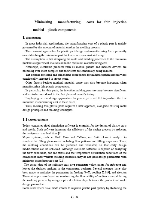
Minimizing manufacturing costs for thin injectionmolded plastic components1. IntroductionIn most industrial applications, the manufacturing cost of a plastic part is mainly governed by the amount of material used in the molding process.Thus, current approaches for plastic part design and manufacturing focus primarily on establishing the minimum part thickness to reduce material usage.The assumption is that designing the mold and molding processes to the minimum thickness requirement should lead to the minimum manufacturing cost. Nowadays, electronic products such as mobile phones and medical devices are becoming ever more complex and their sizes are continually being reduced.The demand for small and thin plastic components for miniaturization assembly has considerably increased in recent years.Other factors besides minimal material usage may also become important when manufacturing thin plastic components.In particular, for thin parts, the injection molding pressure may become significant and has to be considered in the first phase of manufacturing.Employing current design approaches for plastic parts will fail to produce the true minimum manufacturing cost in these cases.Thus, tackling thin plastic parts requires a new approach, alongside existing mold design principles and molding techniques.1.1 Current researchToday, computer-aided simulation software is essential for the design of plastic parts and molds. Such software increases the efficiency of the design process by reducing the design cost and lead time [1].Major systems, such as Mold Flow and C-Flow, use finite element analysis to simulate the filling phenomena, including flow patterns and filling sequences. Thus, the molding conditions can be predicted and validated, so that early design modifications can be achieved. Although available software is capable of analyzing the flow conditions, and the stress and the temperature distribution conditions of the component under various molding scenarios, they do not yield design parameters with minimum manufacturing cost [2,3].The output data of the software only give parameter value ranges for reference and leaves the decision making to the component designer. Several attempts have also been made to optimize the parameters in feeding [4–7], cooling [2,8,9], and ejection These attempts were based on maximizing the flow ability of molten material during the molding process by using empirical relation ships between the product and mold design parameters.Some researchers have made efforts to improve plastic part quality by Reducing thesink mark [11] and the part deformation after molding [12], analyzing the effects of wall thickness and the flow length of the part [13], and analyzing the internal structure of the plastic part design and filling materials flows of the mold design [14]. Reifschneider [15] has compared three types of mold filling simulation programs, including Part Adviser, Fusion, and Insight, with actual experimental testing. All these approaches have established methods that can save a lot of time and cost. However, they just tackled the design parameters of the plastic part and mold individually during the design stage. In addition, they did not provide the design parameters with minimum manufacturing cost.Studies applying various artificial intelligence methods and techniques have been found that mainly focus on optimization analysis of injection molding parameters [16,17]. For in-stance He et al. [3] introduced a fuzzy- neuro approach for automatic resetting of molding process parameters. By contrast , Helps et al. [18,19] adopted artificial neural networks to predict the setting of molding conditions and plastic part quality control in molding. Clearly, the development of comprehensive molding process models and computer-aided manufacturing provides a basis for realizing molding parameter optimization [3 , 16,17]. Mok et al. [20] propose a hybrid neural network and genetic algorithm approach incorporating Case-Based Reasoning (CBR) to derive initial settings for molding parameters for parts with similar design features quickly and with acceptable accuracy. Mok’s approach was based on past product processing data, and was limited to designs that are similar to previous product data. However, no real R&D effort has been found that considers minimizing manufacturing costs for thin plastic components.Generally, the current practical approach for minimizing the manufacturing cost of plastic components is to minimize the thickness and the dimensions of the part at the product design stage, and then to calculate the costs of the mold design and molding process for the part accordingly, as shown in Fig. 1.The current approach may not be able to obtain the real minimum manufacturing cost when handling thin plastic components.1.2Manufacturing requirements for a typical thin plastic component As a test example, the typical manufacturing requirements for a thin square plastic part with a center hole, as shown in Fig. 2,are given in Table 1.Fig.1. The current practical approachFig.2. Test example of a smallplastic componentTable1. Customer requirements for the example component2. The current practical approachAs shown in Fig.1, the current approach consists of three phases: product design, mold design and molding process parameter setting. A main objective in the product design is to establish the physical dimensions of the part such as its thickness, widthand length. The phases of molded sign and molding subsequently treat the established physical dimensions as given inputs to calculate the required details for mold making and molding operations.When applying the current practical approach for tackling the given example, the key variables are handled by the three phases as follows:Product design* Establish the minimum thickness (height) HP, and then calculate the material cost. HP is then treated as a predetermined input for the calculation of the costs of mold design and molding operations. HPMold design* Calculate the cooling time for the determined minimumthickness HP in order to obtain the number of mold cavities required. The mold making cost is then the sum of the costs to machine the:–Depth of cutting (thickness) HP–Number of cavities–Runner diameter DR–Gate thickness HGMolding process* Determine the injection pressure Pin, and then the cost of power consumptionDetermine the cooling time t co, and then the cost of machine operations. The overall molding cost is the sum of the power consumption cost and machine operating cost.The total manufacturing cost is the sum of the costs of plastic material, mold making and molding operations. Note that, in accordance with typical industry practice, all of the following calculations are in terms of unit costs.2.1 Product designThis is the first manufacturing phase of the current practical approach. The design minimizes the thickness HP of the plastic component to meet the creep loading deflection constraint , Y (<1.47mmafter1yearofusage),and to minimize plastic material usage cost Cm. Minimizing HP requires [21]:Figure 3 plots changes in HP through Eqs.1 and 2.The graphs show that the smallest thickness that meets the 1.47mm maximum creep deflection constraint is 0 .75mm,with a plastic material cost of $0.000483558/unit and a batch size of 200000 units.This thickness will be treated as a given input for the subsequent molded sign and molding process analysis phases.2.2Mold design2.2.1 Determination of cooling timeThe desired mold temperature is 25 C. The determined thickness is 0.75mm. Figure 4 shows the cooling channels layout following standard industry practices. The cooling channel diameter is chosen to be 3mm for this example.From [22], the cooling time t co:And the location factor,BysolvingEqs.3and4, and substituting HP =0.75mm and the given values of the cooling channel design parameters, the cooling time (3.1s) is obtained.The cycle time t cycle, given by E q. 5, is proportional to the molding machine operating costs, and consists of injection time (t in), ejection time (t e j), dry cycle time (t d c), and cooling time (t c o).2.2.2 Determination of the number of mold cavities In general, the cost of mold making depends on the amount of machining work to form the required number of cores/cavities, runners, and gates. The given example calls for a two-plate moldFig.3.Deflection and plastic materials costs versus part thickness Fig.4. Cooling channel layout that does not require undercut machining. Therefore, the ma chining work for cutting the runners and gates is proportional to the work involved in forming the cores/cavities and need not be considered. In the example, mold making cost Cmm is governed by (n, HP).Generally, the minimum number of cavities, Nmin, is chosen to allow for delivery of the batch of plastic parts on time图3 。
模具专业术语英文

注塑、模具专业英语Surface Appearance外观Glossiness/gloss finish光洁度、粗糙度Matt finish/matt surface毛面Glass fiber rich surface/glass emergence on the surface玻纤外露、浮纤Blooming/surface blooming表面析出White patches on surface表面白斑Silver marks/silver streak银纹Splay mark水纹、料花Flow mark流纹Brittle/brittleness脆、脆性Bubbles/trapped gas气泡/困气Void孔、气泡Burn marks烧伤FR failed阻燃不合格Flame rating V-2阻燃等级V-2Poor dispersion分散不好FR/PTFE …agglomerates etc阻燃剂/PTFE…结块Pellet porous颗粒料孔隙、Low impact/tensile strength etc低冲击强度/拉伸强度等High flow/filler content etc高流动性/过度填充Longs/fines/doubles长粒/碎屑/连粒Poor cut粒形不好Bristle/voids表面有小气泡/孔Glass bundles纤维结团Product was rejected due to 产品不能接受因为…High moisture level高水分、高湿度Warpage/warped翘曲/变形Shrinkage/shrink收缩/收缩率Sink marks凹陷、缩水Short shot/short molding打不满、欠注Distortion变形Over dimension尺寸过大Under dimension尺寸过小Flashing飞边、披锋、溢边Discoloration变色Off color颜色差异Flow rate流动速率Viscous/viscosity粘性的、粘的/黏度High flow高流动Low flow低流动Sticky粘的,粘性的Sticking core粘后模,粘模芯Sticking sprue粘水口Sticking cavity粘前模Mold release(agent)脱模(剂)Antioxidant抗氧剂Flame retardant agent阻燃剂Heat stabilizer热稳定剂Chopped glass fiber短切玻纤Roving glass fiber粗纱/长玻纤Glass beads玻璃微珠Milled fiber碾磨纤Molybdenum disulfide/moly/MoS2二硫化钼Colorant着色剂Pigment颜料Dye染料Accepted product specification接受产品规格Approved our product认可我们的产品Re-set spec重新定标准Add in extra …添加多一点…Reduced …content减少…含量Dropped/reduced …by x%减少…含量…%Confirmed color standard确认颜色标准Approved color standard认可颜色标准Re-confirmed color standard重新确认颜色标准Qualified our product认可我们的产品Undergoing heat aging test在做热老化实验Product is under testing产品在测试当中Received first order接了第一个定单Expected to finish by …预计在…完成Expected order is xMT预计定单量…吨Estimated annual/monthly consumption预计年/月用量模具方面:Ejection system顶出系统、脱模系统pin顶针、推杆spring弹簧Gate type浇口类型Sprue主流道runner分流道cavity模腔Sprue gate直浇口Pin point gate点浇口Tab gate护耳浇口Fan gate 扇形浇口Tunnel or submarine gate潜伏式浇口Jump gate跳跃式浇口Diaphragm gate片状浇口Ring gate 环形浇口The cavity of the mould模腔Heated cylinder加热料筒Surface finish表面光洁度Sink mark缩水Air trap困气Gas trapped气体困着,困气void空隙,孔galling烧焦Weld line熔接痕,熔合线Drag mark划伤、脱模痕Scratch mark模具刮花Deformed/ warp变形Ejector not returned顶针不回位slide滑块、行位streak波纹、条纹、色痕delamination分层Jetting mark喷射痕Gate mark浇口痕rib筋、加强筋、骨位boss凸台、凸起、凸痕Melt flow length熔体流线长度Ejector plate顶针板Stop pin限位销Push rod推杆、顶针Push back pin复位杆Ejector guide pin顶针导柱Cold-slug-well冷料井、冷料穴plate模板Ejected mark顶痕,顶白nozzle喷嘴Surface defect表面缺陷Air vent排气口Filling uneven走胶不平衡、进胶不平衡pressure:压力speed:速度control:控制protection pressure:保压mold:模set:设定option:选择injection:射胶pressure reducing valve :减压阀relief valve:泄压阀max:最大max:最大system:系统proportional:比例pressure transducer:压力传感器sampling试模pressure sensor压力感应器AMP 伺服放大器trial runrunninggatedosage 溶胶clamp open 开模。
模具术语英文翻译
三、模具塑料模具mould of plastics注塑模具injection mould冲压模具die模架mould base定模座板Top clamping plate Top plateFixed clamp plate水口推板stripper plateA板A plateB板B plate支承板support plate方铁spacer plate底针板ejector plate面针板ejector retainer plate回针Return pin导柱Guide pin有托导套Shoulder Guide bush 直导套Straight Guide bush动模座板Bottom clamp plate Moving clamp plate基准线datum line基准面datum plan型芯固定板core-retainer plate 凸模固定板punch-retainer plate 顶针ejector pin单腔模具single cavity mould多腔模具multi-cavity mould多浇口multi-gating浇口gate缺料starving排气breathing光泽gloss合模力mould clamping force锁模力mould locking force挤出extrusion开裂crack循环时间cycle time老化aging螺杆screw麻点pit嵌件insert活动镶件movable insert起垩chalking浇注系统feed system主流道sprue分流道runner浇口gate直浇口direct gate , sprue gate轮辐浇口spoke gate , spider gate点浇口pin-point gate测浇口edge gate潜伏浇口submarine gate , tunnel gate料穴cold-slug well浇口套sprue bush流道板runner plate排飞槽vent分型线(面)parting line定模stationary mould,Fixed mould动模movable mould, movable half上模upper mould,upper half下模lower mould,lower half型腔cavity凹模cavity plate,cavity block拼块split定位销dowel定位销孔dowel hole型芯core斜销angle pin, finger cam滑块slide滑块导板slide guide strip楔紧块heel block, wedge lock拉料杆sprue puller定位环locating ring冷却通cooling channel脱模斜度draft滑动型芯slide core螺纹型芯threaded core热流道模具hot-runner mould绝热流道模insulated runner mould熔合纹weld line (flow line)三板式模具three plate mould脱模ejection换模腔模具interchangeable cavity mould 脱模剂release agent注射能力shot capacity注射速率injection rate注射压力injection pressure差色剂colorant保压时间holdup time闭模时间closing time定型装置sizing system阴模female mould,cavity block阳模male mould电加工设备Electron Discharge Machining数控加工中心CNC machine center万能铁床Universal milling machine卧式刨床Horizontal planer车床Engine lathe平面磨床Surface grinding machine去磁机Demagnetization machine万能摇臂钻床Universal radial movable driller立式钻床Vertical driller超声波清洗机Ultrasonic clearing machine[此文档可自行编辑修改,如有侵权请告知删除,感谢您的支持,我们会努力把内容做得更好]。
注塑模具翻译
bench work 钳工programmers编程polywood 三夹板,包装用company service服务器part layout排位mold flow模流分析2 shifts两班倒ejector pins顶针ejector sleeve司筒guided bushing导套runner plate流道板cavity inserts镶块force slides滑块bubblers喷井waterline水路interlocks锁模块male interlocks锁模块凸出部分parting line分型面nozzle喷嘴lubricant润滑剂boss安装柱strap安全扣ejector stroke顶出行程accumulate积存clamp plate(A side)a侧复板clearance 空隙间隙relief解除,凸现relief groove退刀槽压力平衡槽gibs凹锲groove槽show in reversed反向显示corners撬模坑pry slot撬模板vented leader pins导柱上需排气center manifold中心集水块water system中心集水块hose水嘴孔gate with 3 drops三点进胶dowel定位销leaf-spring片弹簧melt temperature熔体温度clip slot夹子槽melt flow index熔融指数flowing attribute热变属性clip feature changed 夹具外型已改变ejector board顶针板stripper plate脱模板ejector rods顶料杆retainer pin定位销,嵌件销drop out-opening for ejector part脱模stripper sleeve B脱模套sprue radius(R,radii<semidiameter)喷嘴半径、喷嘴圆角number on the plate模板上的顶针孔编号number on the pin 顶针编号Acrylic Plat亚克力板hot runner area热流道区域oil cylinder油缸oil galleries油道Ftting装配,连接键connect连接或者安装hydraulic components油路连接ejector hole顶出孔(顶针孔或顶片孔)diameter孔径,直径dimension 尺寸Lifting strap起吊环latch插销,锁扣lathe机床cavity insert上内模,定模镶件FE matching FE匹配CMM work三坐标测量工作debugging调试feasibility analysis可行性分析special stocked parts 特殊构件TR技术回标Core insert动模镶件latch lock尼龙拉钩clamp force锁模力filling time注塑时间pvt attribute pvt属性flowing attribute热变属性sprue puller勾针variable变数,参数cavity block,cavity plate凹槽grille格栅radiator水箱leader pin导针rad mill圆角刀date stamper生产日期铭牌back clamp plate复板底面p20 nitrided p20氮化slide stops限位滑块fitting ,connector接头knock-out installed顶出块是否安装runner polished,and corner rounder流道抛光,角要修成圆的male interlock锁模块凸出部分ejector bushing司筒尺寸force slides镶块(滑块)the stripper shoulder bolts推料版拉杆bubblers喷井socket head cap screw沉头螺丝B plate cooling动模水道boss凸起CA guided pin s lots CA导柱排气gripper抓爪,夹具guide bush导套graphite石墨电极hopper漏斗channel/runner流道gate浇口solidification固化burrs毛边(金属)flash飞边tray托盘shot/try out试模lail lamp strength尾灯加强板clamp 夹具rear plate后板ejected顶出Heated barrel加热圆筒内shaper electrode有形状的电极slotted凸槽gear齿轮valve/valveport gate阀门gavges计量表dial caliper游标卡尺screw螺丝sophistatied engraving精雕clamp lock force锁模力bread blast喷砂insulation plate隔热板core pull抽芯injetion machine注塑机型号resert machanism复位机构pick way 取件方式ejector stroke顶出行程gas-assistant machine/device氮气简表,气辅装置/设备posting-process后处理trade-mark材料牌号resin塑胶材料show in reversed反向显示aberration色差burr金属毛边subcontract外包cooling pipe冷却管undercut倒勾finished product成品semi-products半成品cylinder squar圆筒直径flash塑件margin利润nick裂痕parting lock set分模器retainer plate脱料板baffles隔水板(铜制)screw cap螺帽screw thread螺纹large resting pulse大休止脉波(电火花工作原理)tag标口tagging标记texture纹理质感皮纹花纹咬花auto-checking fixture自动化检测装置assistance device辅助设备gas-assisted device气辅设备coverplate盖板fixed clamp定模座板engraving 雕刻fabricating 制造、装配fixture固定装置assembly装配hot-runner热流道notching开槽caps圆槽盖spotting合模die assembly合模die locker锁模器EDW线切割EDM电火花spotting machine合模器injection machine注塑机lathe bench车床pressure controller压力控制器oil temperature controller模温器drilling machine钻床coord3 CMM coords三坐标测量机high-pressure nitrogen Generator高压氮气发生器graphite maching center石墨加工机water cooler 冷水机plot绘图仪calibrator口径测量器milling planer龙门铣床milling head铣头lifespan使用期defects缺陷configuration外形thermoplasticwater-based clayclaydeburr or coin压毛边located block 定位块lowing slide platepolish 抛光,抛亮lapping抛光slide core滑块fumigation熏蒸full round圆流道edge gate侧浇口tunnel gate隧道式浇口pin ejection芯子顶出Hard shell case 硬盒内geometry形状runner plates流道板距离process information 注塑参数locating ring定位圈knockout block顶出块gall被磨伤the back clamp plate复板底面the hole pattern孔型fitting of mold模具元件mold base 模胚core pins模芯销guided ejector顶针板导柱no welding 无焊接chamfer倒角welding line 焊痕loose detail松退dead space避宽(导套啊,导柱这些地方留空隙)opening the mold开模overmold打包模double color双色模ribs筋骨sprue进胶口,喷嘴discoloration变色boss凸台,凸痕heated cylinder加热料筒keep space in compound of parts of injection 避空mold base模胚,模架,模座relief valve安全阀flush with齐平的,使。
注塑模具专业英语
注塑模具专业英语整理: LuisInjection Mold Technical Terms〔一〕模具专业根本用词Professional Terms1.塑料— plastic, resin2.样件— sample3.钢料— steel4.注塑机— injection machine, press5.产品— part, product, moulding6.模具— mold, mould, toolA 简易模〔样板模〕— prototype mold B量产用模具— production mold 7.三维造型〔数模〕—3D model, 3D data8.二维产品图— 2D part drawing9.设计— design10.制造—manufacture, build up, construction, fabrication, make11.检验— check, inspection12.测量— measure, inspection13.修改— change, modify, correction14.工程更改— engineer change15.质量— quality16.数量— quantity17.基准— datum, reference〔二〕如何解析 2D产品图? How to read 2D part drawing?一.产品几何 Geometry1.点— point2.线〔边〕— line, edge3.面 faceA 侧面— side B外表— surface C 外观面— appearance surface 4.壁厚—wall thickness, stock thickness5.加强筋〔骨位〕—rib6.孔—hole7.细长的槽—slot8.柱位—boss9.角—cornerA 圆角— filletB 倒角—chamferC 尖角—sharp corner 10.斜度—angle, taper11. 凹槽— recess , groove二. 分模信息 Splitting1.分型线—parting line (P/L), splitting line2.主分模方向—main direction, line of draw3.浇口设定—gating一.产品标识Part Identification1.产品名称—part name (P/N)2.产品编号 +版本号—part number + revision (Rev.)3.型腔号—cavity number4.材料标记—material symbol5.模具编号—mold number (no.)6.日期印—dating insert, date code7.循环印—cycling code8.公司标志—company logo二. 技术要求 Specification (Special Requirement)1.工程启动表Kick-off sheet1〕工程名称—program name, project name2〕产品名称—part name, product name, part description3〕产品编号—part number (P/N)4〕客户模号—customer mold no.5〕工程启动日期—kick off date, start date6〕工程完成日期—due date, lead time7〕内模件用钢—tool steel8〕型腔数量—number of cavities9〕数据文件编号—data file no.10〕注塑材料—resin, plastic, raw material11〕收缩率—shrink, shrinkage, shrink factor12〕注塑机吨位—molding machine size, injection machine size 13〕成型周期—cycle time14〕型腔光洁度—cavity polish15〕型芯光洁度—core polish16〕皮纹〔晒纹〕—texture, grain17〕拔模斜度—draft angle, removal taper18〕注塑件颜色及光泽—molded color & gloss19〕模具加工地—manufacturing facility20〕热流道供给商—manifold manufacturer, manifold supplier 21〕浇口位置—gate location / position22〕浇口类型—gate type产品标识— stamp information, part identification特殊要求— special instructions1.产品质量及外观要求Part Quality & Appearance Requirement 1〕尺寸及公差Dimension & Tolerance①重要尺寸—critical dimension, important dim., key dim.②理论尺寸—nominal dimension③实际尺寸—actual dimension④公差—tolerance⑤公差带—tolerance range⑥尺寸超差—dimension deviation⑦接受〔合格〕—accept, OK⑧拒绝〔不合格〕—reject, refuse, obsolete, NG⑨让步接受—concession, special admit⑩返工—re-work2〕产品缺陷〔常见的〕Defects (normal)①水— sink mark, shrinkage②,毛— flash, burr③段差— mismatch discrepancy④,蛇— snake marks, streak⑤弯曲,形— warpage, distortion⑥打不〔缺料〕— short shot⑦熔接— weld line⑧多胶— unwanted plastic⑨拉— damage2.品外 Part Appearance①品色— part color②品光— gloss③皮粒度— grain3.常用、及短Normal Word, Short Sentence1〕—per side2〕双— both sides3〕参加,添加— add, incorporate4〕去除,取消— remove, cancel5〕足⋯的要求,符合,与⋯要求一致— according to, conform to, satisfy, meet 6〕要求,需要— require, need, demand7〕确— be approved, agreed by⋯8〕允— permit, allow1〕在⋯范之内—within2〕不可以,不允,禁止—free from, prevent, avoid3〕⋯,除非有另指—⋯ unless otherwise specified4〕⋯或少于—⋯ or less5〕自化运作—automatic operation6〕未注尺寸〔形状〕三造型Non dimensioned contour (detailed shape) see 3D model.7〕分型上的〔披〕或段差小于⋯Burrs o r discrepancy on the P/L shall be⋯or less.Title Block1.品名称—part name2.号+ 版本号〔索引号〕—drawing no. + level (index)3.一般公差—general tolerance〔三〕如何制模准?How to read tooling standard?一.模具构Mold Construction TermsA .模架Mold Base1.模架量化特征Measurement Feature①X X 高— Length X Width X Height②模具高度尺寸〔模厚〕—stack height of mould③模具重量—total weight of mould, mould thickness2.定模底板—front plate, top clamping plate, clamp plate, clamping plate3.定模板—cavity plate, fixed mould plate, A–plate4.动模板—core plate, moving mould plate, B–plate5.支撑板—support plate, backing plate6.间隔板 ,方铁—support blocks, rails, risers, spacer block7.顶杆固定板—retaining plate, ejector retaining plate8.顶板— ejector plate ,bottom clamping plate9.动模底板—back plate10.导柱—guide pillar, leader pin, guide pin11.导套—guide bush, leader pin bush12.复位杆—return pin, push-back pin13.弹簧—spring14.撑头—support pillar15.顶针板导柱、导套—ejection guide pin / bush16.垃圾钉—stop pin, stop button17.模脚—standing-off pillars18.标牌—plaque scutcheonB.成型零部件moulding components1.型芯— core insert2.型腔— cavity insert3.镶针— core pin4.镶块— sub-insert, split5.滑块— slide, sliding split6.斜顶— lifter, angled-lift split, loose coreA 斜顶头— lifter headB 斜顶杆— lifter rod, lifter shaft 7.成型顶杆— moulding face pin, form pinC.浇注系统Feed System1.塑料 Mouldinga.主流道— sprueb.分流道 runner①主分流道— main runner②二级分流道— branch runner 分流道断面形状 cross-sectional shape of runner①圆形— full round②半圆形— semicircular③梯形—trapezoidalc.浇口 gate常用浇口形式 normal gate type :①边缘浇口〔 J 型浇口〕— edge gate, J –gate②侧浇口— side gate③潜伏式浇口— sub-gate, subsurface gate, submarine gate, cashew gate④潜伏式二次浇口 (隧道式浇口 ) — tunnel gate onto feeder post⑤点浇口— pin gate⑥直接浇口 (主流道型浇口 ) — sprue gate, direct gate⑦护耳式浇口— tab gated.模腔— impressione.冷料井—cold slug wellf .热流道—hot runner2.模具零件mold componentsa.定位圈—locating ring, location ring, register ringb.浇口套—sprue bushc.挡圈—stop ringd.浇口镶块—gate inserte.热流道板—manifoldf .热嘴—hot drop hot sprue分型面及其锁紧、排气 Parting Surface, inter-locking & venting1.分型线— parting line ( P/L )2.镶拼线—bodyline, joint line3.平 / 不平的分型面—flat / non–flat parting surface4.封胶面—shut off surfaces, seal-off surfaces5.擦穿位—shut off6.碰穿位—kiss-off7.管位— parting line lock8.分型面的释放(避空 ) — relief of parting surface9.分型面的平衡—balancing of parting surface10.锁紧角度—locking angle11.锁紧力—clamping force12.锁模块—safety strap13.精定位—Interlock, die lock14.困气—air trap15.排气槽—vent, vent slotE.滑块机构Slide1.驱动 Actuation①斜导柱—angle pin, horn pin, cam pin②弹簧—spring③油缸—hydraulic cylinder2.制动Detention①滑块固定器—slide retainer②弹簧制动器—spring-loaded detention (plunger)③挡钉、挡板—stop pin, stop plate, slide stop3.导轨— gib, guide strip4.锁紧块〔楔紧块〕—heel block, locking heel, wedge block, chase block 5.耐磨片—wear plate, wear strip6.压板— retainer, gib7.螺钉— screw8.定位销—dowel pinF.斜顶机构Lifter1.斜顶头—lifter head2.斜顶杆—lifter rod, lifter shaft3.开口销—split pin4.固定板〔压板〕—retainer plate5.耐磨片—wear plate1.铜导套—bronze bushing2.衬套— spacer3.导轨— L –gib4.滑动块—slideG.顶出系统Ejection System1.根本词汇Basic Word①顶出行程— ejection stroke②模具开档— daylight③粘模— stick④产品脱模— part is push off from, clear part of mould, separation of part 2.顶板机构 Ejector plate assembly①顶板— ejector plate②顶板固定板— retaining plate③推板— stripper plate④推板导柱— ejector guide pin⑤推板导套— ejector guide bush⑥撑头— support pillar3.复位机构 Return System①复位杆〔回程杆〕— return pin, push –back pin②垃圾钉— stop pin, stop button③压簧— compressed spring④碟簧— a stack of― Belleville‖ washers⑤早复位机构— early return system⑥强制复位机构— positive return system4.顶出方法 Ejection Techniques1〕顶杆顶出— pin ejection2〕顶管顶出— sleeve ejection3〕顶块顶出— bar ejection4〕扁顶顶出— blade ejection5〕顶板顶出— stripper ejection6〕油缸顶出— hydraulic ejection7〕气顶— air ejection8〕阀门顶出— valve ejection5.顶出元件 Ejection Elements1〕拉料杆— sprue puller, sucker pin2〕顶杆— ejector pin3〕阶梯式顶杆— stepped ejector pin1〕顶管—ejection sleeve, sleeve2〕扁顶—ejector blade, slabbed off ejector pin3〕顶块—stripper bar4〕顶环—stripper ring5〕推板—stripper plate6〕加速顶—accelerated ejection1.顶出辅助机构Supplementary operating system1〕弹簧柱塞器—spring–loaded plunger2〕弹珠定位器—ball catch system3〕插销式锁扣—Latch–lock4〕尼龙拉杆装置—friction puller device2.电器元件Electric Components1〕压力传感器—pressure transducer2〕限位开关—limit switchF.冷却系统Cooling System1.根本词汇Basic Word1〕温差— temperature variation2〕水孔〔水道〕—waterlines, water-ways, flow-way, channel3〕水路— cooling circuit4〕水路示意图—water schematic, schematic circuit5〕冷却液—coolant, coolant fluid6〕内连接—interconnect7〕外连接—external connection8〕出口、入口—outlet、inlet9〕漏水— water leakage2.水路分布Circuits1〕阶梯式水路—stepped system2〕分隔板水路—baffled hole system3〕斜孔式水路—angled hole system3.水路元件Components1〕闷头〔螺塞、止水栓〕—〔 threadless〕 brass pressure plug : female plug & male 2〕隔水片—baffle3〕密封圈—O–ring4〕快插水路接头—quick disconnect fitting, quick connection adaptor5〕弯头— elbow6〕偶合器〔连接器、接头〕—adaptor (including a plug & a socket)7〕橡皮管—rubber hose1〕分水板 ,集水块—water manifoldG.螺纹、螺纹孔& 螺钉Thread, thread hole & screw1.螺纹— thread2.管螺纹—pipe thread3.螺纹孔—screw hole, tapped hole4.起吊孔—handling hole, jack screw hole, eye bolt hole5.螺钉— screw6.内六角螺钉—socket headed cap screw〔s.h.c.s.〕7.沉头螺钉—flat headed cap screw〔〕8.螺栓— bolt9.螺母— nut10.锁紧螺母— locknut11.螺纹标准 Thread Standard①公制标准— Metric②英制标准— Imperial③英制管螺纹标准— British Standard Pipe thread 〔 BSP〕④美制管螺纹标准— NPT⑤美制粗螺纹标准— United Coarse thread 〔 UNC 〕⑥美制细螺纹标准— United Fine thread 〔 UNF 〕H .润滑Lubrication1.润滑槽—grease groove2.加油管—grease line3.油杯— lubrication fittingI. 测量仪器Measuring Instruments1.游标卡尺—vernier caliper2.千分尺—micrometer3.高度规—height gauge4.刻度规—dial gauge5.三坐标测量仪〔三次元〕—Coordinate Measure Machine〔CMM〕6.塞规— pin gauge7.圆角量规—radii gauge8.轮廓投影机— profile projectorJ.注塑机参数Injection Machine Parameter1.注塑机规格参数Injection Machine Specification①锁紧类型 clamp typea.油缸— hydraulic b.肘杆式— toggle②垂直注塑机导柱间距— tie bar vertical clearance③水平注塑机导柱间距— tie bar horizontal clearance④台板尺寸— platen dim.⑤最小 /最大模厚— mold height Min. / Max., Min. / Max. mold thickness⑥最小 /最大注塑机开档— open daylight Min. / Max.⑦锁紧行程— clamp stroke⑧锁紧力— clamping force⑨顶出行程— ejector stroke⑩顶出力— ejector force。
注塑模具相关专业英语:

注塑模具相关专业英语:注射机injection machine三板模:3-plate mold;二板模:2-plate mold;模脚:mold foot动模板movable plate定模板stationary plate水口板runner plate顶针板ejector retainer plate推板ejecting plate方铁space plate动模固定板bottom clamping plate 定模固定板up clamping plate导柱guide pillar导套guide bush回程杆ejector plate return pin回程杆硬块垃圾钉锁模块顶针ejector pin方顶ejector pad斜顶lifter滑块slide斜导柱angle pin垫片wear plate镶件insert动模core定模cavity强行复位机构斜锲wedge顶块ejector pad支撑柱support pillar定位销locating pin运水管water rub tube导滑套bush推管ejector sleeve限位块stop block限位钉stop screw定位圈locating ring浇口套sprue bush活动镶件movable insert排气槽vent斜顶lifter 拉料杆sprue puller分料道拉料杆runner puller圆锥头拉料杆sprue puller, conical headed 扣鸡(尼龙拉钩)nylon latch lock型芯core型腔cavity垫板backing plate浇口gate浇口套口径sprue diameter浇注系统feed system浇口大小gate size直接浇口direct gate环形浇口ring gate侧浇口edge gate盘型浇口disk gate潜伏浇口submarine gate扇形浇口fan gate大水口edge gate细水口pin- point gate转水口switching runner gate流道runner主流道sprue分流道runner梯形流道trapezoidal runner热嘴hot sprue热流道板hot manifold发热管cartridge heater探针thermocouples插头connector plug插座connector socket运水water line喉管tube喉塞lien plug塑胶管plastic tube快速接头jiffy quick connector socket收缩率shrinkage注射压力injection pressure成型压力molding pressure拉伸力drawing force锁模力clamping force开模力mold opening force脱模力ejection force抽芯力core-pulling force 抽芯距core-pulling distance 五金模具相关专业词汇:Progressive forming & punching Die(级进模和冲裁模)凸模垫板 Punch board凹模拼块 Combination die凸模固定板 Punch holder board压料板 Pressing board凹模垫板 Die board小压料板 Mini pressing board小固定板 Mini punch holder下模座 Down mould frame上模座 Up mould frame顶料销b lifter pin b锁模板 Clamping plate导正销a Pilot punches A导正销b Pilot punches b顶料销a lifter pin A侧挡板 Side baffle 抬料块 lifter block固定挡料块 Fixing baffle凸模 Punch导料孚料钉 Guide lifter sets斜契固定板 Cam slide holder斜契 Cam slide units活动呀板 Acting baffle导料孚料钉3 Guide lifter sets 3 导料机构 Guide lifter frameworker 压筋凸模 Pressing punch检测销安装板 Plotes for sensor翻空凸模 Rout up punch压筋凸模2 Pressing punch 2弯边凸模 Bend punch上模座Up mould framestripper guide bushingsstripper guide pins标题栏3、据付板翻边压级模无新词4.据付板拍平冲孔模未显示7.后盖板弯边模无新词9, 2P096439前板1修边冲模第二部分-改模后装配图装配时冲方孔凸模(A)按长短两种间隔排列,如图示技术要求——TECHNOLOGY REQUIREMENT热处理——HEAT TREATING锐角倒钝——Chamfer all the acute edge.所有凸模过孔与凸模配做,带*尺寸与凸模双面间隙0.15-0.20mm,A B C D E F 部及中间大方孔应与相应凸模保证滑动配合。
注塑模具专业英语 塑胶模具英语 注塑成型专业英语 Injection Mould English

abrasive grinding 强力磨削abrasive 磨料的,研磨的absence 不在,缺席accesssory 附件accommodate 适应accordingly 因此,从而,相应地accuracy 精度,准确性actuate 开动(机器),驱动adequate 足够的adhesive 粘合剂adjacent 邻近的adopt 采用advance 进步advisable 可取的agitate 摇动a large extent 很大程度algorithm 算法align 定位,调准alignment 校直all-too-frequent 频繁allowance 容差,余量alternate 交替,轮流alternatively 做为选择,也许aluminiun 铝ample 充足的analysis 分析ancillary 补助的,副的angular 有角的annealing 退火aperture 孔applied loads 作用力appropriate 适当的arc 弧,弓形arise 出现,发生arrange 安排article 制品,产品ascertain 确定,查明assemble 组装attitude 态度auxiliary 辅助的avoid 避免axis 轴axle 轮轴,车轴alternative 替换物backup 备份batch 一批bearing 轴承,支座bed 床身behavior 性能bench-work 钳工工作bend 弯曲beneath 在•••下bin 仓,料架blank 坯料blank 冲裁,落料blanking 落料模blast 一阵(风)blemish 缺点,污点bolster 模座,垫板boring 镗削,镗孔bracket 支架brass 黄铜break down 破坏breakage 破坏brine 盐水brittle 易碎的buffer 缓冲器built-in 内装的bulging 凸肚burr 毛刺bush 衬套by far •••得多,最by means of 借助于boost 推进cabinet 橱柜call upon 要求carbide 碳化物carburzing 渗碳carriage 拖板,大拖板carry along 一起带走carry down over 从•••上取下carry out 完成case hardening 表面硬化case 壳,套cast steel 铸钢casting 铸造,铸件category 种类caution 警告,警示cavity and core plates 凹模和凸模板cavity 型腔,腔,洞centre-drilling 中心孔ceramic 陶瓷制品chain doted line 点划线channel 通道,信道characteristic 特性check 核算chip 切屑,铁屑chuck 卡盘chute 斜道circa 大约circlip (开口)簧环circuit 回路,环路circulate (使)循环clamp 夹紧clamp 压板clay 泥土clearance 间隙clip 切断,夹住cold hobbing 冷挤压cold slug well 冷料井collapse 崩塌,瓦解collapsible 可分解的combination 组合commence 开始,着手commence 开始commercial 商业的competitive 竞争的complementary 互补的complexity 复杂性complication 复杂化compression 压缩comprise 包含compromise 妥协,折衷concern with 关于concise 简明的,简练的confront 使面临connector 连接口,接头consequent 随之发生的,必然的console 控制台consume 消耗,占用consummate 使完善container 容器contingent 可能发生的CPU (central processing unit) 中央处理器conventional 常规的converge 集中于一点conversant 熟悉的conversion 换算,转换conveyer 运送装置coolant 冷却液coordinate (使)协调copy machine 仿形(加工)机床core 型芯,核心corresponding 相应的counteract 反作用,抵抗couple with 伴随contour 轮廓crack (使)破裂,裂纹critical 临界的cross-hatching 剖面线cross-section drawn 剖面图cross-slide 横向滑板CRT (cathoder-ray tube) 阴极射线管crush 压碎cryogenic 低温学的crystal 结晶状的cubic 立方的,立方体的cup (使)成杯状,引伸curable 可矫正的curvature 弧线curve 使弯曲cutter bit 刀头,刀片cyanide 氰化物complicated 复杂的dash 破折号daylight 板距decline 下落,下降,减少deform (使)变形demonstrate 证明depict 描述deposite 放置depression 凹穴descend 下降desirable 合适的detail 细节,详情deterioration 退化,恶化determine 决定diagrammmatic 图解的,图表的dictate 支配die 模具,冲模,凹模dielectric 电介质die-set 模架digital 数字式数字dimensional 尺寸的,空间的discharge 放电,卸下,排出discharge 卸下discrete 离散的,分立的dislodge 拉出,取出dissolution 结束distinct 不同的,显著的distort 扭曲distort (使)变形,扭曲distributed system 分布式系统dowel 销子dramaticlly 显著地drastic 激烈的draughting 绘图draughtsman 起草人drawing 制图drill press 钻床drum 鼓轮dual 双的,双重的ductility 延展性dynamic 动力的edge 边缘e.g.(exempli gratia) [拉]例如ejector 排出器ejector plate 顶出板ejector rob 顶杆elasticity 弹性electric dicharge machining 电火花加工electrode 电极electro-deposition 电铸elementary 基本的eliminate 消除,除去elongate (使)伸长,延长emerge 形成,显现emphasise 强调endeavour 尽力engagement 约束,接合enhance 提高,增强ensure 确保,保证erase 抹去,擦掉evaluation 评价,估价eventually 终于evolution 进展excecution 执行,完成execute 执行electrochemical machining 电化学加工exerte 施加experience 经验explosive 爆炸(性)的extend 伸展external 外部的extract 拔出extreme 极端extremely 非常地extremity 极端extrusion 挤压,挤出envisage 设想Fahrenheit 华氏温度fabricate 制作,制造flat-panel technology 平面(显示)技术facility 设备facing 端面车削fall within 属于,适合于fan 风扇far from 毫不,一点不,远非fatigue 疲劳feasible 可行的feature 特色,特征feed 进给feedback 反馈female 阴的,凹形的ferrule 套管file system 文件系统fitter 装配工,钳工fix 使固定,安装fixed half and moving half 定模和动模facilitate 帮助flexibility 适应性,柔性flexible 柔韧的flow mark 流动斑点follow-on tool 连续模foregoing 在前的,前面的foretell 预测,预示,预言forge 锻造forming 成型four screen quadrants 四屏幕象限fracture 破裂free from 免于gap 裂口,间隙gearbox 齿轮箱govern 统治,支配,管理grain 纹理graphic 图解的grasp 抓住grid 格子,网格grind 磨,磨削,研磨grinding 磨光,磨削grinding machine 磨床gripper 抓爪,夹具groove 凹槽guide bush 导套guide pillar 导柱guide pillars and bushes 导柱和导套handset 电话听筒hardness 硬度hardware 硬件headstock 床头箱,主轴箱hexagonal 六角形的,六角的hindrance 障碍,障碍物hob 滚刀,冲头hollow-ware 空心件horizontal 水平的hose 软管,水管hyperbolic 双曲线的i.e. (id est) [拉]也就是identical 同样的identify 确定,识别idle 空闲的immediately 正好,恰好impact 冲击impart 给予implement 实现impossibility 不可能impression 型腔in contact with 接触in terms of 依据inasmuch (as) co因为,由于inch-to-metric conversions 英公制转换inclinable 可倾斜的inclusion 内含物inconspicuous 不显眼的incorporate 合并,混合indentation 压痕indenter 压头independently 独自地,独立地inevitably 不可避免地inexpensive 便宜的inherently 固有的injection mould 注塑模injection 注射in-line-of-draw 直接脱模insert 嵌件inserted die 嵌入式凹模inspection 检查,监督installation 安装integration 集成intelligent 智能的intentinonally 加强地,集中地interface 界面internal 内部的interpolation 插值法investment casting 熔模铸造irregular 不规则的,无规律irrespective of 不论,不管irrespective 不顾的,不考虑的issue 发布,发出joint line 结合线kerosene 煤油keyboard 健盘knock 敲,敲打lance 切缝lathe 车床latitude 自由lay out 布置limitation 限度,限制,局限(性) local intelligence 局部智能locate 定位logic 逻辑longitudinal 纵向的longitudinally 纵向的look upon 视作,看待lubrication 润滑machine shop 车间machine table 工作台machining 加工made-to-measure 定做maintenance 维护,维修majority 多数make use of 利用male 阳的,凸形的malfunction 故障mandrel 心轴manifestation 表现,显示massiveness 厚实,大块measure 大小,度量microcomputer 微型计算机microns 微米microprocessor 微处理器mild steel 低碳钢milling machine 铣床mineral 矿物,矿产minimise 把减到最少,最小化minute 微小的mirror image 镜像mirror 镜子moderate 适度的modification 修改,修正modulus 系数mold 模,铸模mold 制模,造型monitor 监控monograph 专著more often than not 常常motivation 动机mould split line 模具分型线moulding 注塑件move away from 抛弃multi-imprssion mould 多型腔模narrow 狭窄的NC (numerical control) 数控nevertheless 然而,不过nonferrous 不含铁的,非铁的normally 通常地novice 新手,初学者nozzle 喷嘴,注口numerical 数字的objectionable 有异议的,讨厌的observe 观察obviously 明显地off-line 脱机的on-line 联机operational 操作的,运作的opportunity 时机,机会opposing 对立的,对面的opposite 反面optimization 最优化orient 确定方向orthodox 正统的,正规的overall 全面的,全部的overbend 过度弯曲overcome 克服,战胜overlaping 重叠overriding 主要的,占优势的opposite 对立的,对面的pack 包装package 包装pallet 货盘panel 面板paraffin 石蜡parallel 平行的penetration 穿透peripheral 外围的periphery 外围permit 许可,允许pessure casting 压力铸造pillar 柱子,导柱pin 销,栓,钉pin-point gate 针点式浇口piston 活塞plan view 主视图plasma 等离子plastic 塑料platen 压板plotter 绘图机plunge 翻孔plunge 投入plunger 柱塞pocket-size 袖珍portray 描绘pot 壶pour 灌,注practicable 行得通的preferable 更好的,更可取的preliminary 初步的,预备的press setter 装模工press 压,压床,冲床,压力机prevent 妨碍primarily 主要地procedure 步骤,方法,程序productivity 生产力profile 轮廓progressively 渐进地project 项目project 凸出projection 突出部分proper 本身的property 特性prototype 原形proximity 接近prudent 谨慎的punch 冲孔punch shapper tool 刨模机punch-cum-blanking die 凹凸模punched tape 穿孔带purchase 买,购买push back pin 回程杆pyrometer 高温计quality 质量quandrant 象限quantity 量,数量quench 淬火radial 放射状的ram 撞锤rapid 迅速的rapidly 迅速地raster 光栅raw 未加工的raw material 原材料ream 铰大reaming 扩孔,铰孔recall 记起,想起recede 收回,后退recess 凹槽,凹座,凹进处redundancy 过多re-entrant 凹入的refer 指,涉及,谈及reference 参照,参考refresh display 刷新显示register ring 定位环register 记录,显示,记数regrind 再磨研relative 相当的,比较的relay 继电器release 释放relegate 把降低到reliability 可靠性relief valves 安全阀relief 解除relieve 减轻,解除remainder 剩余物,其余部分removal 取出remove 切除,切削reposition 重新安排represent 代表,象征reputable 有名的,受尊敬的reservoir 容器,储存器resident 驻存的resist 抵抗resistance 阻力,抵抗resolution 分辨率respective 分别的,各自的respond 响应,作出反应responsibility 责任restrain 抑制restrict 限制,限定restriction 限制retain 保持,保留retaining plate 顶出固定板reveal 显示,展现reversal 反向right-angled 成直角的rigidity 钢度rod 杆,棒rotate (使)旋转rough machining 粗加工rough 粗略的routine 程序rubber 橡胶runner and gate systems 流道和浇口系统sand casting 砂型铸造satisfactorily 满意地saw 锯子scale 硬壳score 刻划scrap 废料,边角料,切屑screwcutting 切螺纹seal 密封section cutting plane 剖切面secure 固定secure 紧固,夹紧,固定segment 分割sensitive 敏感的sequence 次序sequential 相继的seriously 严重地servomechanism 伺服机构servomotor 伺服马达setter 安装者set-up 机构sever 切断severity 严重shaded 阴影的shank 柄shear 剪,切shot 注射shrink 收缩side sectional view 侧视图signal 信号similarity 类似simplicity 简单single-point cutting tool 单刃刀具situate 使位于,使处于slide 滑动,滑落slideway 导轨slot 槽slug 嵌条soak 浸,泡,均热software 软件solid 立体,固体solidify (使)凝固solidify (使)固化solution 溶液sophisiticated 尖端的,完善的sound 结实的,坚固的spark erosion 火花蚀刻spindle 主轴spline 花键split 侧向分型,分型spool 线轴springback 反弹spring-loaded 装弹簧的sprue bush 主流道衬套sprue puller 浇道拉杆square 使成方形Servomechanism Laboratoies 伺服机构实验室stage 阶段standardisation 标准化startling 令人吃惊的steadily 稳定地step-by-step 逐步stickiness 粘性stiffness 刚度stock 毛坯,坯料storage tube display 储存管显示storage 储存器straightforward 直接的strain 应变strength 强度stress 压力,应力stress-strain 应力--应变stretch 伸展strike 冲击stringent 严厉的stripper 推板stroke 冲程,行程structrural build-up 结构上形成的sub-base 垫板subject 使受到submerge 淹没subsequent 后来的subsequently 后来,随后substantial 实质的substitute 代替,替换subtract 减,减去suitable 合适的,适当的suitably 合适地sunk 下沉,下陷superior 上好的susceptible 易受影响的sweep away 扫过symmetrical 对称的synchronize 同步,同时发生tactile 触觉的,有触觉的tailstock 尾架tapered 锥形的tapping 攻丝technique 技术tempering 回火tendency 趋向,倾向tensile 拉力的,可拉伸的tension 拉紧,张紧terminal 终端机terminology 术语,用辞theoretically 理论地thereby 因此,从而thermoplastic 热塑性的thermoplastic 热塑性塑料thermoset 热固性thoroughly 十分地,彻底地thread pitch 螺距thread 螺纹thrown up 推上tilt 倾斜,翘起tolerance 公差two-plate mould 双板式注射模tong 火钳tonnage 吨位,总吨数tool point 刀锋tool room 工具车间toolholder 刀夹,工具柄toolmaker 模具制造者toolpost grinder 工具磨床toolpost 刀架torsional 扭转的toughness 韧性trace 追踪transverse 横向的tray 盘,盘子,蝶treatment 处理tremendous 惊人的,巨大的trend 趋势trigger stop 始用挡料销tungsten 钨turning 车削twist 扭曲,扭转tracer-controlled milling machine 仿形铣床ultimately 终于undercut moulding 侧向分型模undercut 侧向分型undercut 底切underfeed 底部进料的undergo 经受underside 下面,下侧undue 不适当的,过度的uniform 统一的,一致的utilize 利用Utopian 乌托邦的,理想化的valve 阀vaporize 汽化vaporize (使)蒸发variation 变化various 不同的,各种的vector feedrate computation 向量进刀速率计算vee 字形velocity 速度versatile 多才多艺的,万用的vertical 垂直的via prep经,通过vicinity 附近viewpoint 观点wander 偏离方向warp 翘曲washer 垫圈wear 磨损well line 结合线whereupon 于是winding 绕,卷with respect to 相对于withstand 经受,经得起work 工件workstage 工序wrinkle 皱纹使皱yield 生产zoom 图象电子放大。
注塑模具设计技术中英文对照外文翻译文献
中英文资料对照外文翻译英文:Design and Technology of the Injection Mold1、3D solid model to replace the center layer modelThe traditional injection molding simulation software based on products of the center layer model. The user must first be thin-walled plastic products abstract into approximate plane and curved surface, the surface is called the center layer. In the center layer to generate two-dimensional planar triangular meshes, the use of these two-dimensional triangular mesh finite element method, and the final result of the analysis in the surface display. Injection product model using3D solid model, the two models are inconsistent, two modeling inevitable. But because of injection molding product shape is complex and diverse, the myriads of changes from athree-dimensional entity, abstraction of the center layer is a very difficult job, extraction process is very cumbersome and time-consuming, so the design of simulation software have fear of difficulty, it has become widely used in injection molding simulation software the bottleneck.HSCAE3D is largely accepted3D solid / surface model of the STL file format. Now the mainstream CAD/CAM system, such as UG, Pro/ENGINEER, CATIA and SolidWorks, can output high quality STL format file. That is to say, the user can use any commercial CAD/CAE systems to generate the desired products3D geometric model of the STL format file, HSCAE3D can automatically add the STL file into a finite element mesh model, through the surface matching and introduction of a new boundary conditions to ensure coordination of corresponding surface flow, based on3D solid model of analysis, and display of three-dimensional analysis results, replacing the center layer simulation technology to abstract the center layer, and then generate mesh this complicated steps, broke through system simulation application bottlenecks, greatly reducing the burden of user modeling, reduces the technical requirement of the user, the user training time from the past few weeks shorter for a fewhours. Figure 1 is based on the central layer model and surface model based on 3D solid / flow analysis simulation comparison chart.2、Finite element, finite difference, the control volume methodsInjection molding products are thin products, products in the thickness direction of size is much smaller than the other two dimensions, temperature and other physical quantities in the thickness direction of the change is very large, if the use of a simple finite element and finite difference method will cause analysis time is too long, can not meet the actual needs of mold design and manufacturing. We in the flow plane by using finite element method, the thickness direction by using finite difference method, were established and plane flow and thickness directions corresponding to the size of the grid and coupling, while the accuracy is guaranteed under the premise of the calculation speed to meet the need of engineering application, and using the control volume method is solved. The moving boundary problem in. For internal and external correspondence surface differences between products, can be divided into two parts the volume, and respectively formed the control equation, the junction of interpolation to ensure thatthe two part harmony contrast.3、Numerical analysis and artificial intelligence technologyOptimization of injection molding process parameters has been overwhelming majority of mold design staff concerns, the traditional CAE software while in computer simulation of a designated under the conditions of the injection molding conditions, but is unable to automatically optimize the technical parameters. Using CAE software personnel must be set to different process conditions were multiple CAE analysis, combined with practical experience in the program were compared between, can get satisfactory process scheme. At the same time, the parts after the CAE analysis, the system will generate a large amount of information about the project ( product, process, analyzes the results ), which often results in a variety of data form, requiring the user to have the analysis and understanding of the results of CAE analysis ability, so the traditional CAE software is a kind of passive computational tools, can provide users with intuitionistic, effective engineering conclusion, to software users demand is too high, the influence of CAE system in the larger scope of application and popularization. In view of the above, HSCAE3D software in the original CAE system based on accurate calculationfunction, the knowledge engineering technology is introduced the system development, the use of artificial intelligence is the ability of thinking and reasoning, instead of the user to complete a large number of information analysis and processing work, directly provide guiding significance for the process of conclusions and recommendations, effectively solve the CAE of the complexity of the system and the requirements of the users of the contradiction between, shortening of the CAE system and the distance between the user, the simulation software by traditional " passive" computational tools to " active" optimization system. HSCAE3D system artificial intelligence technology will be applied to the initial design, the results of the analysis of CAE interpretation and evaluation, improvement and optimization analysis of3 aspects.译文:注塑模具设计的技术1.用三维实体模型取代中心层模型传统的注塑成形仿真软件基于制品的中心层模型。
模具术语英文翻译

三、模具塑料模具mould of plastics注塑模具injection mould冲压模具die模架mould base定模座板Top clamping plate Top plateFixed clamp plate水口推板stripper plateA板A plateB板B plate支承板support plate方铁spacer plate底针板ejector plate面针板ejector retainer plate回针Return pin导柱Guide pin有托导套Shoulder Guide bush 直导套Straight Guide bush动模座板Bottom clamp plate Moving clamp plate基准线datum line基准面datum plan型芯固定板core-retainer plate 凸模固定板punch-retainer plate 顶针ejector pin单腔模具single cavity mould多腔模具multi-cavity mould多浇口multi-gating浇口gate缺料starving排气breathing光泽gloss合模力mould clamping force锁模力mould locking force挤出extrusion开裂crack循环时间cycle time老化aging螺杆screw麻点pit嵌件insert活动镶件movable insert起垩chalking浇注系统feed system主流道sprue分流道runner浇口gate直浇口direct gate , sprue gate轮辐浇口spoke gate , spider gate点浇口pin-point gate测浇口edge gate潜伏浇口submarine gate , tunnel gate料穴cold-slug well浇口套sprue bush流道板runner plate排飞槽vent分型线(面)parting line定模stationary mould,Fixed mould动模movable mould, movable half上模upper mould,upper half下模lower mould,lower half型腔cavity凹模cavity plate,cavity block拼块split定位销dowel定位销孔dowel hole型芯core斜销angle pin, finger cam滑块slide滑块导板slide guide strip楔紧块heel block, wedge lock拉料杆sprue puller定位环locating ring冷却通cooling channel脱模斜度draft滑动型芯slide core螺纹型芯threaded core热流道模具hot-runner mould绝热流道模insulated runner mould熔合纹weld line (flow line)三板式模具three plate mould脱模ejection换模腔模具interchangeable cavity mould 脱模剂release agent注射能力shot capacity注射速率injection rate注射压力injection pressure差色剂colorant保压时间holdup time闭模时间closing time定型装置sizing system阴模female mould,cavity block阳模male mould电加工设备Electron Discharge Machining数控加工中心CNC machine center万能铁床Universal milling machine卧式刨床Horizontal planer车床Engine lathe平面磨床Surface grinding machine去磁机Demagnetization machine万能摇臂钻床Universal radial movable driller 立式钻床Vertical driller超声波清洗机Ultrasonic clearing machine。
塑胶模具中英文对照表格

塑胶模具中英文对照表格全文共四篇示例,供您参考第一篇示例:| 中文| 英文||--------------|----------------------|| 塑胶模具| Plastic mold || 注塑模具| Injection mold || 压铸模具| Die-casting mold || 挤出模具| Extrusion mold || 压延模具| Calendering mold || 吹塑模具| Blow molding mold || 压缩成型模具| Compression mold || 热压模具| Hot pressing mold || 橡胶模具| Rubber mold || 泡沫模具| Foam mold || 旋转模具| Rotational mold || 热流道模具| Hot runner mold || 冷流道模具| Cold runner mold || 多腔模具| Multi-cavity mold || 单腔模具| Single-cavity mold || 涡流模具| Vortex mold || 滚筒模具| Roller mold || 注塑机| Injection molding machine | | 压铸机| Die-casting machine || 吹塑机| Blow molding machine || 挤出机| Extrusion machine || 压延机| Calendering machine || 注塑料| Injection molding material | | 塑胶注射| Plastic injection || 模具设计| Mold design || 模具制造| Mold manufacturing || 模具加工| Mold processing || 模具试模| Mold trial || 模具保养| Mold maintenance || 模具寿命| Mold life || 模具材料| Mold material || 模具制造商| Mold manufacturer |以上是关于塑胶模具中英文对照表格的内容,希望对您有所帮助。
注塑模具英语词汇
注塑模具英语词汇-CAL-FENGHAI.-(YICAI)-Company One1注塑模具英语词汇一、工程部 / Design department:1) Designer - 设计师。
2) Assembly drawing - 模具组装图。
3) Mold layout - 模具结构图。
4) 2D product drawing - 2D产品图。
5) 3D product data - 3D产品数据。
6) Part drawing - 散件图。
7) Insert molding - 镶件模。
8) 2 color mold / Double injection tool - 双色模。
9) Hydraulic system - 油/水压系统。
10) Parting line - 分模线。
11) Air venting - 排气槽。
12) Cooling system - 冷却系统。
13) Screw - 镙丝。
14) Hot runner system - 热流道。
15) Valve gate - 伐针入水口。
16) Fan gate - 扇型入水口。
17) Pin point gate - 针点进胶。
18) Moon gate / Banana gate - 香蕉,象牙入水口。
19) Submarine gate - 潜水口。
20) Injection machine tonnage - 注塑机吨数。
21) Number of cavity - 穴数。
22) Steel - 钢材。
23) Copper - 铜。
24) Tungsten copper - 钨铜。
25) Beryllium copper - 铍铜。
26) Hardening - 加硬/淬火。
27) Tempering - 回火。
28) Chroming - 电镀。
29) Painting - 喷漆。
30) Resin - 胶材。
31) Printing - 丝印。
模具术语英文翻译
三、模具塑料模具mould of plastics注塑模具injection mould冲压模具die模架mould base定模座板Top clamping plate Top plateFixed clamp plate水口推板stripper plateA板A plateB板B plate支承板support plate方铁spacer plate底针板ejector plate面针板ejector retainer plate回针Return pin导柱Guide pin有托导套Shoulder Guide bush 直导套Straight Guide bush动模座板Bottom clamp plate Moving clamp plate基准线datum line基准面datum plan型芯固定板core-retainer plate 凸模固定板punch-retainer plate 顶针ejector pin单腔模具single cavity mould多腔模具multi-cavity mould多浇口multi-gating浇口gate缺料starving排气breathing光泽gloss合模力mould clamping force锁模力mould locking force挤出extrusion开裂crack循环时间cycle time老化aging螺杆screw麻点pit嵌件insert活动镶件movable insert起垩chalking浇注系统feed system主流道sprue分流道runner浇口gate直浇口direct gate , sprue gate轮辐浇口spoke gate , spider gate点浇口pin-point gate测浇口edge gate潜伏浇口submarine gate , tunnel gate料穴cold-slug well浇口套sprue bush流道板runner plate排飞槽vent分型线(面)parting line定模stationary mould,Fixed mould动模movable mould, movable half上模upper mould,upper half下模lower mould,lower half型腔cavity凹模cavity plate,cavity block拼块split定位销dowel定位销孔dowel hole型芯core斜销angle pin, finger cam滑块slide滑块导板slide guide strip楔紧块heel block, wedge lock拉料杆sprue puller定位环locating ring冷却通cooling channel脱模斜度draft滑动型芯slide core螺纹型芯threaded core热流道模具hot-runner mould绝热流道模insulated runner mould熔合纹weld line (flow line)三板式模具three plate mould脱模ejection换模腔模具interchangeable cavity mould 脱模剂release agent注射能力shot capacity注射速率injection rate注射压力injection pressure差色剂colorant保压时间holdup time闭模时间closing time定型装置sizing system阴模female mould,cavity block阳模male mould电加工设备Electron Discharge Machining数控加工中心CNC machine center万能铁床Universal milling machine卧式刨床Horizontal planer车床Engine lathe平面磨床Surface grinding machine去磁机Demagnetization machine万能摇臂钻床Universal radial movable driller 立式钻床Vertical driller超声波清洗机Ultrasonic clearing machine。
注塑模具中英文对照外文翻译文献
中英文对照资料外文翻译Integrated simulation of the injection molding process withstereolithography moldsAbstract Functional parts are needed for design verification testing, field trials, customer evaluation, and production planning. By eliminating multiple steps, the creation of the injection mold directly by a rapid prototyping (RP) process holds the best promise of reducing the time and cost needed to mold low-volume quantities of parts. The potential of this integration of injection molding with RP has been demonstrated many times. What is missing is the fundamental understanding of how the modifications to the mold material and RP manufacturing process impact both the mold design and the injection molding process. In addition, numerical simulation techniques have now become helpful tools of mold designers and process engineers for traditional injection molding. But all current simulation packages for conventional injection molding are no longer applicable to this new type of injection molds, mainly because the property of the mold material changes greatly. In this paper, an integrated approach to accomplish a numerical simulation of injection molding into rapid-prototyped molds is established and a corresponding simulation system is developed. Comparisons with experimental results are employed for verification, which show that the present scheme is well suited to handle RP fabricated stereolithography (SL) molds.Keywords Injection molding Numerical simulation Rapid prototyping1 IntroductionIn injection molding, the polymer melt at high temperature is injected into the mold under high pressure [1]. Thus, the mold material needs to have thermal and mechanical properties capable of withstanding the temperatures and pressures of the molding cycle. The focus of many studies has been to create theinjection mold directly by a rapid prototyping (RP) process. By eliminating multiple steps, this method of tooling holds the best promise of reducing the time and cost needed to createlow-volume quantities of parts in a production material. The potential of integrating injection molding with RP technologies has been demonstrated many times. The properties of RP molds are very different from those of traditional metal molds. The key differences are the properties of thermal conductivity and elastic modulus (rigidity). For example, the polymers used in RP-fabricated stereolithography (SL) molds have a thermal conductivity that is less than one thousandth that of an aluminum tool. In using RP technologies to create molds, the entire mold design and injection-molding process parameters need to be modified and optimized from traditional methodologies due to the completely different tool material. However, there is still not a fundamental understanding of how the modifications to the mold tooling method and material impact both the mold design and the injection molding process parameters. One cannot obtain reasonable results by simply changing a few material properties in current models. Also, using traditional approaches when making actual parts may be generating sub-optimal results. So there is a dire need to study the interaction between the rapid tooling (RT) process and material and injection molding, so as to establish the mold design criteria and techniques for an RT-oriented injection molding process.In addition, computer simulation is an effective approach for predicting the quality of molded parts. Commercially available simulation packages of the traditional injection molding process have now become routine tools of the mold designer and process engineer [2]. Unfortunately, current simulation programs for conventional injection molding are no longer applicable to RP molds, because of the dramatically dissimilar tool material. For instance, in using the existing simulation software with aluminum and SL molds and comparing with experimental results, though the simulation values of part distortion are reasonable for the aluminum mold, results are unacceptable, with the error exceeding 50%. The distortion during injection molding is due to shrinkage and warpage of the plastic part, as well as the mold. For ordinarily molds, the main factor is the shrinkage and warpage of the plastic part, which is modeled accurately in current simulations. But for RP molds, the distortion of the mold has potentially more influence, which have been neglected in current models. For instance, [3] used a simple three-step simulation process to consider the mold distortion, which had too much deviation.In this paper, based on the above analysis, a new simulation system for RP molds is developed. The proposed system focuses on predicting part distortion, which is dominating defect in RP-molded parts. The developed simulation can be applied as an evaluation tool for RP mold design and process opti mization. Our simulation system is verified by an experimental example.Although many materials are available for use in RP technologies, we concentrate on usingstereolithography (SL), the original RP technology, to create polymer molds. The SL process uses photopolymer and laser energy to build a part layer by layer. Using SL takes advantage of both the commercial dominance of SL in the RP industry and the subsequent expertise base that has been developed for creating accurate, high-quality parts. Until recently, SL was primarily used to create physical models for visual inspection and form-fit studies with very limited func-tional applications. However, the newer generation stereolithographic photopolymers have improved dimensional, mechanical and thermal properties making it possible to use them for actual functional molds.2 Integrated simulation of the molding process2.1 MethodologyIn order to simulate the use of an SL mold in the injection molding process, an iterative method is proposed. Different software modules have been developed and used to accomplish this task. The main assumption is that temperature and load boundary conditions cause significant distortions in the SL mold. The simulation steps are as follows:1The part geo metry is modeled as a solid model, which is translated to a file readable by the flow analysis package.2Simulate the mold-filling process of the melt into a pho topolymer mold, which will output the resulting temperature and pressure profiles.3Structural analysis is then performed on the photopolymer mold model using the thermal and load boundary conditions obtained from the previous step, which calculates the distortion that the mold undergo during the injection process.4If the distortion of the mold converges, move to the next step. Otherwise, the distorted mold cavity is then modeled (changes in the dimensions of the cavity after distortion), and returns to the second step to simulate the melt injection into the distorted mold.5The shrinkage and warpage simulation of the injection molded part is then applied, which calculates the final distor tions of the molded part.In above simulation flow, there are three basic simulation mod ules.2. 2 Filling simulation of the melt2.2.1 Mathematical modelingIn order to simulate the use of an SL mold in the injection molding process, an iterativemethod is proposed. Different software modules have been developed and used to accomplish this task. The main assumption is that temperature and load boundary conditions cause significant distortions in the SL mold. The simulation steps are as follows:1. The part geometry is modeled as a solid model, which is translated to a file readable by the flow analysis package.2. Simulate the mold-filling process of the melt into a photopolymer mold, which will output the resulting temperature and pressure profiles.3. Structural analysis is then performed on the photopolymer mold model using the thermal and load boundary conditions obtained from the previous step, which calculates the distortion that the mold undergo during the injection process.4. If the distortion of the mold converges, move to the next step. Otherwise, the distorted mold cavity is then modeled (changes in the dimensions of the cavity after distortion), and returns to the second step to simulate the melt injection into the distorted mold.5. The shrinkage and warpage simulation of the injection molded part is then applied, which calculates the final distortions of the molded part.In above simulation flow, there are three basic simulation modules.2.2 Filling simulation of the melt2.2.1 Mathematical modelingComputer simulation techniques have had success in predicting filling behavior in extremely complicated geometries. However, most of the current numerical implementation is based on a hybrid finite-element/finite-difference solution with the middleplane model. The application process of simulation packages based on this model is illustrated in Fig. 2-1. However, unlike the surface/solid model in mold-design CAD systems, the so-called middle-plane (as shown in Fig. 2-1b) is an imaginary arbitrary planar geometry at the middle of the cavity in the gap-wise direction, which should bring about great inconvenience in applications. For example, surface models are commonly used in current RP systems (generally STL file format), so secondary modeling is unavoidable when using simulation packages because the models in the RP and simulation systems are different. Considering these defects, the surface model of the cavity is introduced as datum planes in the simulation, instead of the middle-plane.According to the previous investigations [4–6], fillinggoverning equations for the flow and temperature field can be written as:where x, y are the planar coordinates in the middle-plane, and z is the gap-wise coordinate; u, v,w are the velocity components in the x, y, z directions; u, v are the average whole-gap thicknesses; and η, ρ,CP (T), K(T) represent viscosity, density, specific heat and thermal conductivity of polymer melt, respectively.Fig.2-1 a–d. Schematic procedure of the simulation with middle-plane model. a The 3-D surface model b The middle-plane model c The meshed middle-plane model d The display of the simulation result In addition, boundary conditions in the gap-wise direction can be defined as:where TW is the constant wall temperature (shown in Fig. 2a).Combining Eqs. 1–4 with Eqs. 5–6, it follows that the distributions of the u, v, T, P at z coordinates should be symmetrical, with the mirror axis being z = 0, and consequently the u, v averaged in half-gap thickness is equal to that averaged in wholegap thickness. Based on this characteristic, we can divide the whole cavity into two equal parts in the gap-wise direction, as described by Part I and Part II in Fig. 2b. At the same time, triangular finite elements are generated in the surface(s) of the cavity (at z = 0 in Fig. 2b), instead of the middle-plane (at z = 0 in Fig. 2a). Accordingly, finite-difference increments in the gapwise direction are employed only in the inside of the surface(s) (wall to middle/center-line), which, in Fig. 2b, means from z = 0 to z = b. This is single-sided instead of two-sided with respect to the middle-plane (i.e. from the middle-line to two walls). In addition, the coordinate system is changed from Fig. 2a to Fig. 2b to alter the finite-element/finite-difference scheme, as shown in Fig. 2b. With the above adjustment, governing equations are still Eqs. 1–4. However, the original boundary conditions inthe gapwise direction are rewritten as:Meanwhile, additional boundary conditions must be employed at z = b in order to keep the flows at the juncture of the two parts at the same section coordinate [7]:where subscripts I, II represent the parameters of Part I and Part II, respectively, and Cm-I and Cm-II indicate the moving free melt-fronts of the surfaces of the divided two parts in the filling stage.It should be noted that, unlike conditions Eqs. 7 and 8, ensuring conditions Eqs. 9 and 10 are upheld in numerical implementations becomes more difficult due to the following reasons:1. The surfaces at the same section have been meshed respectively, which leads to a distinctive pattern of finite elements at the same section. Thus, an interpolation operation should be employed for u, v, T, P during the comparison between the two parts at the juncture.2. Because the two parts have respective flow fields with respect to the nodes at point A and point C (as shown in Fig. 2b) at the same section, it is possible to have either both filled or one filled (and one empty). These two cases should be handled separately, averaging the operation for the former, whereas assigning operation for the latter.3. It follows that a small difference between the melt-fronts is permissible. That allowance can be implemented by time allowance control or preferable location allowance control of the melt-front nodes.4. The boundaries of the flow field expand by each melt-front advancement, so it is necessary to check the condition Eq. 10 after each change in the melt-front.5. In view of above-mentioned analysis, the physical parameters at the nodes of the same section should be compared and adjusted, so the information describing finite elements of the same section should be prepared before simulation, that is, the matching operation among the elements should be preformed.Fig. 2a,b. Illustrative of boundary conditions in the gap-wise direction a of the middle-plane model b of thesurface model2.2.2 Numerical implementationPressure field. In modeling viscosity η, which is a function of shear rate, temperature and pressure of melt, the shear-thinning behavior can be well represented by a cross-type model such as:where n corresponds to the power-law index, and τ∗ characterizes the shear stress level of the transition region between the Newtonian and power-law asymptotic limits. In terms of an Arrhenius-type temperature sensitivity and exponential pressure dependence, η0(T, P) can be represented with reasonable accuracy as follows:Equations 11 and 12 constitute a five-constant (n, τ∗, B, Tb, β) representation for viscosity. The shear rate for viscosity calculation is obtained by:Based on the above, we can infer the following filling pressure equation from the governing Eqs. 1–4:where S is calculated by S = b0/(b−z)2η d z. Applying the Galerkin method, the pressure finite-element equation is deduced as:where l_ traverses all elements, including node N, and where I and j represent the local node number in element l_ corresponding to the node number N and N_ in the whole, respectively. The D(l_) ij is calculated as follows:where A(l_) represents triangular finite elements, and L(l_) i is the pressure trial function in finite elements.Temperature field. To determine the temperature profile across the gap, each triangular finite element at the surface is further divided into NZ layers for the finite-difference grid.The left item of the energy equation (Eq. 4) can be expressed as:where TN, j,t represents the temperature of the j layer of node N at time t.The heat conduction item is calculated by:where l traverses all elements, including node N, and i and j represent the local node number in element l corresponding to the node number N and N_ in the whole, respectively.The heat convection item is calculated by:For viscous heat, it follows that:Substituting Eqs. 17–20 into the energy equation (Eq. 4), the temperature equation becomes:2.3 Structural analysis of the moldThe purpose of structural analysis is to predict the deformation occurring in the photopolymer mold due to the thermal and mechanical loads of the filling process. This model is based on a three-dimensional thermoelastic boundary element method (BEM). The BEM is ideally suited for this application because only the deformation of the mold surfaces is of interest. Moreover, the BEM has an advantage over other techniques in that computing effort is not wasted on calculating deformation within the mold.The stresses resulting from the process loads are well within the elastic range of the mold material. Therefore, the mold deformation model is based on a thermoelastic formulation. The thermal and mechanical properties of the mold are assumed to be isotropic and temperature independent.Although the process is cyclic, time-averaged values of temperature and heat flux are used for calculating the mold deformation. Typically, transient temperature variations within a mold have been restricted to regions local to the cavity surface and the nozzle tip [8]. The transients decay sharply with distance from the cavity surface and generally little variation is observed beyond distances as small as 2.5 mm. This suggests that the contribution from the transients to the deformation at the mold block interface is small, and therefore it is reasonable to neglect the transient effects. The steady state temperature field satisfies Laplace’s equation 2T = 0 and the time-averaged boundary conditions. The boundary conditions on the mold surfaces are described in detail by Tang et al. [9]. As for the mechanical boundary conditions, the cavity surface is subjected to the melt pressure, the surfaces of the mold connected to the worktable are fixed in space, and other external surfaces are assumed to be stress free.The derivation of the thermoelastic boundary integral formulation is well known [10]. It is given by:where uk, pk and T are the displacement, traction and temperature,α, ν represent the thermal expansion coefficient and Poisson’s ratio of the material, and r = |y−x|. clk(x) is the surfacecoefficient which depends on the local geometry at x, the orientation of the coordinate frame and Poisson’s ratio for the domain [11]. The fundamental displacement ˜ulk at a point y in the xk direction, in a three-dimensional infinite isotropic elastic domain, results from a unit load concentrated at a point x acting in the xl direction and is of the form:where δlk is the Kronecker delta function and μ is the shear modulus of the mold material.The fundamental traction ˜plk , measured at the point y on a surface with unit normal n, is:Discretizing the surface of the mold into a total of N elements transforms Eq. 22 to:where Γn refers to the n th surface element on the domain.Substituting the appropriate linear shape functions into Eq. 25, the linear boundary element formulation for the mold deformation model is obtained. The equation is applied at each node on the discretized mold surface, thus giving a system of 3N linear equations, where N is the total number of nodes. Each node has eight associated quantities: three components of displacement, three components of traction, a temperature and a heat flux. The steady state thermal model supplies temperature and flux values as known quantities for each node, and of the remaining six quantities, three must be specified. Moreover, the displacement values specified at a certain number of nodes must eliminate the possibility of a rigid-body motion or rigid-body rotation to ensure a non-singular system of equations. The resulting system of equations is assembled into a integrated matrix, which is solved with an iterative solver.2.4 Shrinkage and warpage simulation of the molded partInternal stresses in injection-molded components are the principal cause of shrinkage and warpage. These residual stresses are mainly frozen-in thermal stresses due to inhomogeneous cooling, when surface layers stiffen sooner than the core region, as in free quenching. Based onthe assumption of the linear thermo-elastic and linear thermo-viscoelastic compressible behavior of the polymeric materials, shrinkage and warpage are obtained implicitly using displacement formulations, and the governing equations can be solved numerically using a finite element method.With the basic assumptions of injection molding [12], the components of stress and strain are given by:The deviatoric components of stress and strain, respectively, are given byUsing a similar approach developed by Lee and Rogers [13] for predicting the residual stresses in the tempering of glass, an integral form of the viscoelastic constitutive relationships is used, and the in-plane stresses can be related to the strains by the following equation:Where G1 is the relaxation shear modulus of the material. The dilatational stresses can be related to the strain as follows:Where K is the relaxation bulk modulus of the material, and the definition of α and Θ is:If α(t) = α0, applying Eq. 27 to Eq. 29 results in:Similarly, applying Eq. 31 to Eq. 28 and eliminating strain εxx(z, t) results in:Employing a Laplace transform to Eq. 32, the auxiliary modulus R(ξ) is given by:Using the above constitutive equation (Eq. 33) and simplified forms of the stresses and strains in the mold, the formulation of the residual stress of the injection molded part during the cooling stage is obtain by:Equation 34 can be solved through the application of trapezoidal quadrature. Due to the rapid initial change in the material time, a quasi-numerical procedure is employed for evaluating the integral item. The auxiliary modulus is evaluated numerically by the trapezoidal rule.For warpage analysis, nodal displacements and curvatures for shell elements are expressed as:where [k] is the element stiffness matrix, [Be] is the derivative operator matrix, {d} is the displacements, and {re} is the element load vector which can be evaluated by:The use of a full three-dimensional FEM analysis can achieve accurate warpage results, however, it is cumbersome when the shape of the part is very complicated. In this paper, a twodimensional FEM method, based on shell theory, was used because most injection-molded parts have a sheet-like geometry in which the thickness is much smaller than the other dimensions of the part. Therefore, the part can be regarded as an assembly of flat elements to predict warpage. Each three-node shell element is a combination of a constant strain triangular element (CST) and a discrete Kirchhoff triangular element (DKT), as shown in Fig. 3. Thus, the warpage can be separated into plane-stretching deformation of the CST and plate-bending deformation of the DKT, and correspondingly, the element stiffness matrix to describe warpage can also be divided into the stretching-stiffness matrix and bending-stiffness matrix.Fig. 3a–c. Deformation decomposition of shell element in the local coordinate system. a In-plane stretchingelement b Plate-bending element c Shell element3 Experimental validationTo assess the usefulness of the proposed model and developed program, verification is important. The distortions obtained from the simulation model are compared to the ones from SL injection molding experiments whose data is presented in the literature [8]. A common injection molded part with the dimensions of 36×36×6 mm is considered in the experiment, as shown in Fig. 4. The thickness dimensions of the thin walls and rib are both 1.5 mm; and polypropylene was used as the injection material. The injection machine was a production level ARGURY Hydronica 320-210-750 with the following process parameters: a melt temperature of 250 ◦C; an ambient temperature of 30 ◦C; an injection pressure of 13.79 MPa; an injection time of 3 s; and a cooling time of 48 s. The SL material used, Dupont SOMOSTM 6110 resin, has the ability to resist temperatures of up to 300 ◦C temperatures. As mentioned above, thermal conductivity of the mold is a major factor that differentiates between an SL and a traditional mold. Poor heat transfer in the mold would produce a non-uniform temperature distribution, thus causing warpage that distorts the completed parts. For an SL mold, a longer cycle time would be expected. The method of using a thin shell SL mold backed with a higher thermal conductivity metal (aluminum) was selected to increase thermal conductivity of the SL mold.Fig. 4. Experimental cavity modelFig. 5. A comparison of the distortion variation in the X direction for different thermal conductivity; where “Experimental”, “present”, “three-step”, and “conventional” mean the results of the experimental, the presented simulation, the three-step simulation process and the conventional injection molding simulation, respectively.Fig. 6. Comparison of the distortion variation in the Y direction for different thermal conductivitiesFig. 7. Comparison of the distortion variation in the Z direction for different thermal conductivitiesFig. 8. Comparison of the twist variation for different thermal conductivities For this part, distortion includes the displacements in three directions and the twist (the difference in angle between two initially parallel edges). The validation results are shown in Fig.5 to Fig. 8. These figures also include the distortion values predicted by conventional injection molding simulation and the three-step model reported in [3].4 ConclusionsIn this paper, an integrated model to accomplish the numerical simulation of injection molding into rapid-prototyped molds is established and a corresponding simulation system is developed. For verification, an experiment is also carried out with an RPfabricated SL mold.It is seen that a conventional simulation using current injection molding software breaks down for a photopolymer mold. It is assumed that this is due to the distortion in the mold caused by the temperature and load conditions of injection. The three-step approach also has much deviation. The developed model gives results closer to experimental.Improvement in thermal conductivity of the photopolymer significantly increases part quality. Since the effect of temperature seems to be more dominant than that of pressure (load), an improvement in the thermal conductivity of the photopolymer can improve the part quality significantly.Rapid Prototyping (RP) is a technology makes it possible to manufacture prototypes quickly and inexpensively, regardless of their complexity. Rap id Tooling (RT) is the next step in RP’s steady progress and much work is being done to obtain more accurate tools to define the parameters of the process. Existing simulation tools can not provide the researcher with a useful means of studying relative changes. An integrated model, such as the one presented in this paper, is necessary to obtain accurate predictions of the actual quality of final parts. In the future, we expect to see this work expanded to develop simulations program for injection into RP molds manufactured by other RT processes.References1. Wang KK (1980) System approach to injection molding process. Polym-Plast Technol Eng 14(1):75–93.2. Shelesh-Nezhad K, Siores E (1997) Intelligent system for plastic injection molding process design. J Mater Process Technol 63(1–3):458–462.3. Aluru R, Keefe M, Advani S (2001) Simulation of injection molding into rapid-prototyped molds. Rapid Prototyping J 7(1):42–51.4. Shen SF (1984) Simulation of polymeric flows in the injection molding process. Int J Numer Methods Fluids 4(2):171–184.5. Agassant JF, Alles H, Philipon S, Vincent M (1988) Experimental and theoretical study of the injection molding of thermoplastic materials. Polym Eng Sci 28(7):460–468.6. Chiang HH, Hieber CA, Wang KK (1991) A unified simulation of the filling and post-filling stages in injection molding. Part I: formulation. Polym Eng Sci 31(2):116–124.7. Zhou H, Li D (2001) A numerical simulation of the filling stage in injection molding based on a surface model. Adv Polym Technol 20(2):125–131.8. Himasekhar K, Lottey J, Wang KK (1992) CAE of mold cooling in injection molding using a three-dimensional numerical simulation. J EngInd Trans ASME 114(2):213–221.9. Tang LQ, Pochiraju K, Chassapis C, Manoochehri S (1998) Computeraided optimization approach for the design of injection mold cooling systems. J Mech Des, Trans ASME 120(2):165–174.10. Rizzo FJ, Shippy DJ (1977) An advanced boundary integral equation method for three-dimensional thermoelasticity. Int J Numer Methods Eng 11:1753–1768.11. Hartmann F (1980) Computing the C-matrix in non-smooth boundary points. In: New developments in boundary element methods, CML Publications, Southampton, pp 367–379.12. Chen X, Lama YC, Li DQ (2000) Analysis of thermal residual stress in plastic injection molding. J Mater Process Technol 101(1):275–280.13. Lee EH, Rogers TG (1960) Solution of viscoelastic stress analysis problems using measured creep or relaxation function. J Appl Mech 30(1):127–134.14. Li Y (1997) Studies in direct tooling using stereolithography. Dissertation, University of Delaware, Newark, DE..。
注塑模具专业英语

注塑模具专业英语Injection Mold Technical Terms(一)模具专业基本用词Professional Terms1.塑料— plastic, resin2.样件— sample3.钢料— steel4.注塑机— injection machine, press5.产品— part, product, moulding6.模具— mold, mould, toolA 简易模(样板模)— prototype moldB 量产用模具—production mold 7.三维造型(数模)—3D model, 3D data8.二维产品图— 2D part drawing9.设计— design10.制造— manufacture, build up, construction, fabrication, make11.检验— check, inspection12.测量— measure, inspection13.修改— change, modify, correction14.工程更改— engineer change15.质量— quality16.数量— quantity17.基准— datum, reference(二)如何解析2D 产品图?How to read 2D part drawing?一.产品几何Geometry1.点— point2.线(边)— line, edge3.面faceA 侧面— sideB 表面— surfaceC 外观面—appearance surface 4.壁厚—wall thickness, stock thickness5.加强筋(骨位)— rib6.孔— hole7.细长的槽— slot8.柱位— boss9.角— cornerA 圆角— filletB 倒角— chamferC 尖角— sharp corner 10.斜度— angle, taper11. 凹槽—recess , groove二. 分模信息Splitting1.分型线— parting line (P/L), splitting line2.主分模方向— main direction, line of draw3.浇口设定— gating一.产品标识Part Identification1.产品名称— part name (P/N)2.产品编号+版本号— part number + revision (Rev.)3.型腔号— cavity number4.材料标记— material symbol5.模具编号— mold number (no.)6.日期印— dating insert, date code7.循环印— cycling code8.公司标志— company logo二. 技术要求Specification (Special Requirement)1.项目启动表Kick-off sheet1)项目名称— program name, project name2)产品名称— part name, product name, part description3)产品编号— part number (P/N)4)客户模号— customer mold no.5)项目启动日期— kick off date, start date6)项目完成日期— due date, lead time7)内模件用钢— tool steel8)型腔数量— number of cavities9)数据文件编号— data file no.10)注塑材料— resin, plastic, raw material11)收缩率— shrink, shrinkage, shrink factor12)注塑机吨位—molding machine size, injection machine size 13)成型周期— cycle time14)型腔光洁度— cavity polish15)型芯光洁度— core polish16)皮纹(晒纹)— texture, grain17)拔模斜度— draft angle, removal taper18)注塑件颜色及光泽— molded color & gloss19)模具加工地— manufacturing facility20)热流道供应商—manifold manufacturer, manifold supplier 21)浇口位置— gate location / position22)浇口类型— gate type产品标识— stamp information, part identification特殊要求— special instructions1.产品质量及外观要求Part Quality & Appearance Requirement 1)尺寸及公差Dimension & Tolerance①重要尺寸— critical dimension, important dim., key dim.②理论尺寸— nominal dimension③实际尺寸— actual dimension④公差— tolerance⑤公差带— tolerance range⑥尺寸超差— dimension deviation⑦接受(合格)— accept, OK⑧拒绝(不合格)— reject, refuse, obsolete, NG⑨让步接受— concession, special admit⑩返工— re-work2)产品缺陷(常见的)Defects (normal)①缩水— sink mark, shrinkage②飞边,毛边— flash, burr③段差— mismatch discrepancy④银丝纹,蛇纹— snake marks, streak⑤弯曲,变形— warpage, distortion⑥打不饱(缺料)— short shot⑦熔接线— weld line⑧多胶— unwanted plastic⑨拉伤—damage2.产品外观Part Appearance①产品颜色— part color②产品光泽— gloss③皮纹粒度— grain3.常用词汇、词组及短语Normal Word, Short Sentence1)单边— per side2)双边— both sides3)加入,添加— add, incorporate4)去除,取消— remove, cancel5)满足…的要求,符合,与…要求一致—according to, conform to, satisfy, meet 6)要求,需要— require, need, demand 7)确认—be approved, agreed by …8)允许— permit, allow1)在…范围之内— within2)不可以,不允许,禁止— free from, prevent, avoid3)…,除非有另指—… unless otherwise specified4)…或少于—…or less5)自动化运作— automatic operation6)未注尺寸(详细形状)见三维造型Non dimensioned contour (detailed shape) see 3D model.7)分型线上的飞边(披缝)或段差应小于…Burrs o r discrepancy on t he P/L shall be … or less.标题栏Title Block1.产品名称— part name2.图纸编号+ 版本号(索引号)— drawing no. + level (index) 3.一般公差— general tolerance(三)如何阅读制模标准?How to read tooling standard?一.模具结构术语Mold Construction TermsA.模架Mold Base1.模架量化特征Measurement Feature①长X 宽X 高— Length X Width X Height②模具高度尺寸(模厚)— stack height of mould③模具重量— total weight of mould, mould thickness2.定模底板— front plate, top clamping plate, clamp plate, clamping plate3.定模板— cavity plate, fixed mould plate, A – plate4.动模板— core plate, moving mould plate, B – plate5.支撑板— support plate, backing plate6.间隔板,方铁— support blocks, rails, risers, spacer block7.顶杆固定板— retaining plate, ejector retaining plate8.顶板— ejector plate,bottom clamping plate9.动模底板— back plate10.导柱— guide pillar, leader pin, guide pin11.导套— guide bush, leader pin bush12.复位杆— return pin, push-back pin13.弹簧— spring14.撑头— support pillar15.顶针板导柱、导套— ejection guide pin / bush16.垃圾钉— stop pin, stop button17.模脚— standing-off pillars18.标牌— plaque scutcheonB.成型零部件moulding components1.型芯— core insert2.型腔— cavity insert3.镶针— core pin4.镶块— sub-insert, split5.滑块— slide, sliding split6.斜顶— lifter, angled-lift split, loose coreA 斜顶头— lifter headB 斜顶杆— lifter rod, lifter shaft 7.成型顶杆— moulding face pin, form pinC.浇注系统Feed System1.塑料Mouldinga.主流道— sprueb.分流道runner①主分流道—main runner ②二级分流道— branch runner 分流道断面形状cross-sectional shape of runner①圆形— full round②半圆形— semicircular③梯形—trapezoidalc.浇口gate常用浇口形式normal gate type :①边缘浇口(J型浇口)— edge gate, J – gate②侧浇口— side gate③潜伏式浇口—sub-gate, subsurface gate, submarine gate, cashew gate④潜伏式二次浇口(隧道式浇口) — tunnel gate onto feeder post⑤点浇口— pin gate⑥直接浇口(主流道型浇口) — sprue gate, direct gate⑦护耳式浇口— tab gated.模腔— impressione.冷料井— cold slug wellf.热流道— hot runner2.模具零件mold componentsa.定位圈— locating ring, location ring, register ringb.浇口套— sprue bushc.挡圈— stop ringd.浇口镶块— gate inserte.热流道板— manifoldf.热嘴— hot drop\hot sprue分型面及其锁紧、排气Parting Surface, inter-locking & venting 1.分型线— parting line ( P/L )2.镶拼线— bodyline, joint line3.平/ 不平的分型面— flat / non – flat parting surface 4.封胶面— shut off surfaces, seal-off surfaces5.擦穿位— shut off6.碰穿位— kiss-off7.管位— parting line lock8.分型面的释放(避空) — relief of parting surface9.分型面的平衡— balancing of parting surface10.锁紧角度— locking angle11.锁紧力— clamping force12.锁模块— safety strap13.精定位— Interlock, die lock14.困气— air trap15.排气槽— vent, vent slotE.滑块机构Slide1.驱动Actuation①斜导柱— angle pin, horn pin, cam pin②弹簧— spring③油缸— hydraulic cylinder2.制动Detention①滑块固定器— slide retainer②弹簧制动器— spring-loaded detention (plunger)③挡钉、挡板— stop pin, stop plate, slide stop3.导轨— gib, guide strip4.锁紧块(楔紧块)— heel block, locking heel, wedge block, chase block 5.耐磨片— wear plate, wear strip6.压板— retainer, gib7.螺钉— screw8.定位销— dowel pinF.斜顶机构Lifter1.斜顶头— lifter head2.斜顶杆— lifter rod, lifter shaft3.开口销— split pin4.固定板(压板)— retainer plate5.耐磨片— wear plate1.铜导套— bronze bushing2.衬套— spacer3.导轨— L – gib4.滑动块— slideG.顶出系统Ejection System1.基本词汇Basic Word①顶出行程— ejection stroke②模具开档— daylight③粘模— stick④产品脱模—part is push off from, clear part of mould,separation of part 2.顶板机构Ejector plate assembly①顶板— ejector plate②顶板固定板— retaining plate③推板— stripper plate④推板导柱— ejector guide pin⑤推板导套— ejector guide bush⑥撑头— support pillar3.复位机构Return System①复位杆(回程杆)— return pin, push – back pin②垃圾钉— stop pin, stop button③压簧— compressed spring④碟簧—a stack of ―Belleville‖ washers⑤早复位机构— early return system⑥强制复位机构— positive return system4.顶出方法Ejection Techniques1)顶杆顶出— pin ejection2)顶管顶出— sleeve ejection3)顶块顶出— bar ejection4)扁顶顶出— blade ejection5)顶板顶出— stripper ejection6)油缸顶出— hydraulic ejection7)气顶— air ejection8)阀门顶出— valve ejection5.顶出元件Ejection Elements1)拉料杆— sprue puller, sucker pin2)顶杆— ejector pin3)阶梯式顶杆— stepped ejector pin1)顶管— ejection sleeve, sleeve2)扁顶— ejector blade, slabbed off ejector pin3)顶块— stripper bar4)顶环— stripper ring5)推板— stripper plate6)加速顶— accelerated ejection1.顶出辅助机构Supplementary operating system1)弹簧柱塞器— spring – loaded plunger2)弹珠定位器— ball catch system3)插销式锁扣— Latch – lock4)尼龙拉杆装置— friction puller device2.电器元件Electric Components1)压力传感器— pressure transducer2)限位开关— limit switchF.冷却系统Cooling System1.基本词汇Basic Word1)温差— temperature variation2)水孔(水道)— waterlines, water-ways, flow-way, channel 3)水路— cooling circuit4)水路示意图— water schematic, schematic circuit5)冷却液— coolant, coolant fluid6)内连接— interconnect7)外连接— external connection8)出口、入口— outlet、inlet9)漏水— water leakage2.水路分布Circuits1)阶梯式水路— stepped system2)分隔板水路— baffled hole system3)斜孔式水路— angled hole system3.水路元件Components1)闷头(螺塞、止水栓)—(threadless)brass pressure plug : female plug & male 2)隔水片— baffle3)密封圈— O – ring4)快插水路接头— quick disconnect fitting, quick connection adaptor5)弯头— elbow6)偶合器(连接器、接头)— adaptor (including a plug & a socket)7)橡皮管— rubber hose1)分水板,集水块— water manifoldG.螺纹、螺纹孔& 螺钉Thread, thread hole & screw1.螺纹— thread2.管螺纹— pipe thread3.螺纹孔— screw hole, tapped hole4.起吊孔— handling hole, jack screw hole, eye bolt hole5.螺钉— screw6.内六角螺钉— socket headed cap screw (s.h.c.s.)7.沉头螺钉— flat headed cap screw (f.h.c.s)8.螺栓— bolt9.螺母— nut10.锁紧螺母— locknut11.螺纹标准Thread Standard①公制标准— Metric②英制标准— Imperial③英制管螺纹标准— British Standard Pipe thread (BSP)④美制管螺纹标准— NPT⑤美制粗螺纹标准— United Coarse thread (UNC)⑥美制细螺纹标准— United Fine thread (UNF)H.润滑Lubrication1.润滑槽— grease groove2.加油管— grease line3.油杯— lubrication fittingI. 测量仪器Measuring Instruments1.游标卡尺— vernier caliper2.千分尺— micrometer3.高度规— height gauge4.刻度规— dial gauge5.三坐标测量仪(三次元)—Coordinate Measure Machine (CMM)6.塞规— pin gauge7.圆角量规— radii gauge8.轮廓投影机—profile projectorJ.注塑机参数Injection Machine Parameter1.注塑机规格参数Injection Machine Specification①锁紧类型clamp typea.油缸— hydraulic b.肘杆式— toggle②垂直注塑机导柱间距— tie bar vertical clearance③水平注塑机导柱间距— tie bar horizontal clearance④台板尺寸— platen dim.⑤最小/ 最大模厚— mold height Min. / Max., Min. / Max. mold thickness⑥最小/ 最大注塑机开档— open daylight Min. / Max.⑦锁紧行程— clamp stroke⑧锁紧力— clamping force⑨顶出行程— ejector stroke⑩顶出力— ejector force。
注塑模具英语词汇

注塑模具英语词汇(总3页)--本页仅作为文档封面,使用时请直接删除即可----内页可以根据需求调整合适字体及大小--注塑模具英语词汇一、工程部 / Design department:1) Designer - 设计师。
2) Assembly drawing - 模具组装图。
3) Mold layout - 模具结构图。
4) 2D product drawing - 2D产品图。
5) 3D product data - 3D产品数据。
6) Part drawing - 散件图。
7) Insert molding - 镶件模。
8) 2 color mold / Double injection tool - 双色模。
9) Hydraulic system - 油/水压系统。
10) Parting line - 分模线。
11) Air venting - 排气槽。
12) Cooling system - 冷却系统。
13) Screw - 镙丝。
14) Hot runner system - 热流道。
15) Valve gate - 伐针入水口。
16) Fan gate - 扇型入水口。
17) Pin point gate - 针点进胶。
18) Moon gate / Banana gate - 香蕉,象牙入水口。
19) Submarine gate - 潜水口。
20) Injection machine tonnage - 注塑机吨数。
21) Number of cavity - 穴数。
22) Steel - 钢材。
23) Copper - 铜。
24) Tungsten copper - 钨铜。
25) Beryllium copper - 铍铜。
26) Hardening - 加硬/淬火。
27) Tempering - 回火。
28) Chroming - 电镀。
29) Painting - 喷漆。
30) Resin - 胶材。
模具术语英文翻译
三、模具塑料模具 mould of plastics注塑模具 injection mould冲压模具 die模架 mould base定模座板 Top clamping plateTop plateFixed clamp plate水口推板 stripper plateA 板 A plateB 板 B plate支承板 support plate方铁 spacer plate底针板 ejector plate面针板 ejector retainer plate回针 Return pin导柱 Guide pin有托导套 Shoulder Guide bush直导套 Straight Guide bush动模座板 Bottom clamp plateMoving clamp plate基准线 datum line基准面 datum plan型芯固定板 core-retainer plate 凸模固定板 punch-retainer plate 顶针 ejector pin单腔模具 single cavity mould多腔模具 multi-cavity mould多浇口 multi-gating浇口 gate缺料 starving排气 breathing光彩 gloss合模力 mould clamping force锁模力 mould locking force挤出 extrusion开裂 crack循环时间 cycle time老化 aging螺杆 screw麻点 pit嵌件 insert活动镶件 movable insert起垩 chalking浇注系统 feed system主流道 sprue分流道 runner浇口 gate直浇口 direct gate , sprue gate轮辐浇口 spoke gate , spider gate点浇口 pin-point gate测浇口 edge gate潜藏浇口 submarine gate , tunnel gate 料穴 cold-slug well浇口套 sprue bush流道板 runner plate排飞槽 vent分型线(面) parting line定模 stationary mould,Fixed mould 动模 movable mould, movable half上模 upper mould,upper half下模 lower mould ,lower half型腔 cavity凹模 cavity plate,cavity block拼块 split定位销 dowel定位销孔 dowel hole型芯 core斜销 angle pin, finger cam滑块 slide滑块导板 slide guide strip楔紧块 heel block, wedge lock拉料杆 sprue puller定位环 locating ring冷却通 cooling channel脱模斜度 draft滑动型芯 slide core螺纹型芯 threaded core热流道模具 hot-runner mould绝热流道模 insulated runner mould熔合纹 weld line(flow line )三板式模具 three plate mould脱模 ejection换模腔模具 interchangeable cavity mould脱模剂 release agent注射能力 shot capacity注射速率 injection rate注射压力 injection pressure差色剂 colorant保压时间 holdup time闭模时间 closing time定型装置 sizing system阴模 female mould,cavity block阳模 male mould电加工设施 Electron Discharge Maching数控加工中心CNC machine center全能铁床 Universal milling machine卧式刨床 Horizontal planer车床 Engine lathe平面磨床 Surface grinding machine全能摇臂钻床 Universal radial movable driller 立式钻床 Vertical driller超声波冲洗机Ultrasonic clearing machine。
塑料注塑模具论文中英文对照资料外文翻译文献

外文资料翻译及原文【原文一】CONCURRENT DESIGN OF PLASTICS INJECTION MOULDS AbstractThe plastic product manufacturing industry has been growing rapidly in recent years. One of the most popular processes for making plastic parts is injection moulding. The design of injection mould is critically important to product quality and efficient product processing.Mould-making companies, who wish to maintain the competitive edge, desire to shorten both design and manufacturing leading times of the by applying a systematic mould design process. The mould industry is an important support industry during the product development process, serving as an important link between the product designer and manufacturer. Product development has changed from the traditional serial process of design, followed by manufacture, to a more organized concurrent process where design and manufacture are considered at a very early stage of design. The concept of concurrent engineering (CE) is no longer new and yet it is still applicable an d relevant in today’s manuf acturing environment. Team working spirit, management involvement, total design process and integration of IT tools are still the essence of CE. The application of The CE process to the design of an injection process involves the simultaneous consideration of plastic part design, mould design and injection moulding machineselection, production scheduling and cost as early as possible in the design stage.This paper presents the basic structure of an injection mould design. The basis of this system arises from an analysis of the injection mould design process for mould design companies. This injection mould design system covers both the mould design process and mould knowledge management. Finally the principle of concurrent engineering process is outlined and then its principle is applied to the design of a plastic injection mould.Keywords :Plastic injection mould design, Concurrent engineering, Computer aided engineering, Moulding conditions, Plastic injection moulding, Flow simulation1.IntroductionInjection moulds are always expensive to make, unfortunately without a mould it can not be possible ho have a moulded product. Every mould maker has his/her own approach to design a mould and there are many different ways of designing and building a mould. Surely one of the most critical parameters to be considered in the design stage of the mould is the number of cavities, methods of injection, types of runners, methods of gating, methods of ejection, capacity and features of the injection moulding machines. Mould cost, mould quality and cost of mould product are inseparableIn today’s completive environment, computer aided mould filling simulation packages can accurately predict the fill patterns of any part. This allows for quick simulations of gate placements and helps finding the optimal location. Engineers can perform moulding trials on the computer before the part design is completed. Process engineers can systematically predict a design and process window, and can obtain information about the cumulative effect of the process variables that influence part performance, cost, and appearance.2.Injection MouldingInjection moulding is one of the most effective ways to bring out the best in plastics. It is universally used to make complex, finished parts, often in a single step, economically, precisely and with little waste. Mass production of plastic parts mostly utilizes moulds. Themanufacturing process and involving moulds must be designed after passing through the appearance evaluation and the structure optimization of the product design. Designers face a huge number of options when they create injection-moulded components. Concurrent engineering requires an engineer to consider the manufacturing process of the designed product in the development phase. A good design of the product is unable to go to the market if its manufacturing process is impossible or too expensive. Integration of process simulation, rapid prototyping and manufacturing can reduce the risk associated with moving from CAD to CAM and further enhance the validity of the product development.3. Importance of Computer Aided Injection Mould DesignThe injection moulding design task can be highly complex. Computer Aided Engineering (CAE) analysis tools provide enormous advantages of enabling design engineers to consider virtually and part, mould and injection parameters without the real use of any manufacturing and time. The possibility of trying alternative designs or concepts on the computer screen gives the engineers the opportunity to eliminate potential problems before beginning the real production. Moreover, in virtual environment, designers can quickly and easily asses the sensitivity of specific moulding parameters on the quality and manufacturability of the final product. All theseCAE tools enable all these analysis to be completed in a meter of days or even hours, rather than weeks or months needed for the real experimental trial and error cycles. As CAE is used in the early design of part, mould and moulding parameters, the cost savings are substantial not only because of best functioning part and time savings but also the shortens the time needed to launch the product to the market.The need to meet set tolerances of plastic part ties in to all aspects of the moulding process, including part size and shape, resin chemical structure, the fillers used, mould cavity layout, gating, mould cooling and the release mechanisms used. Given this complexity, designers often use computer design tools, such as finite element analysis (FEA) and mould filling analysis (MFA), to reduce development time and cost. FEA determines strain, stress and deflection in a part by dividing the structure into small elements where these parameters can be well defined. MFA evaluates gate position and size to optimize resin flow. It also defines placement of weld lines, areas of excessive stress, and how wall and rib thickness affect flow. Other finite element designtools include mould cooling analysis for temperature distribution, and cycle time and shrinkage analysis for dimensional control and prediction of frozen stress and warpage.The CAE analysis of compression moulded parts is shown in Figure 1. The analysis cycle starts with the creation of a CAD model and a finite element mesh of the mould cavity. After the injection conditions are specified, mould filling, fiber orientation, curing and thermal history, shrinkage and warpage can be simulated. The material properties calculated by the simulation can be used to model the structural behaviour of the part. If required, part design, gate location and processing conditions can be modified in the computer until an acceptable part is obtained. After the analysis is finished an optimized part can be produced with reduced weldline (known also knitline), optimized strength, controlled temperatures and curing, minimized shrinkage and warpage.Machining of the moulds was formerly done manually, with a toolmaker checking each cut. This process became more automated with the growth and widespread use of computer numerically controlled or CNC machining centres. Setup time has also been significantly reduced through the use of special software capable of generating cutter paths directly from a CAD data file. Spindle speeds as high as 100,000 rpm provide further advances in high speed machining. Cutting materials have demonstrated phenomenal performance without the use of any cutting/coolant fluid whatsoever. As a result, the process of machining complex cores and cavities has been accelerated. It is good news that the time it takes to generate a mould is constantly being reduced. The bad news, on the other hand, is that even with all these advances, designing and manufacturing of the mould can still take a long time and can be extremely expensive.Figure 1 CAE analysis of injection moulded partsMany company executives now realize how vital it is to deploy new products to market rapidly. New products are the key to corporate prosperity. They drive corporate revenues, market shares, bottom lines and share prices. A company able to launch good quality products with reasonable prices ahead of their competition not only realizes 100% of the market before rival products arrive but also tends to maintain a dominant position for a few years even after competitive products have finally been announced (Smith, 1991). For most products, these two advantages are dramatic. Rapid product development is now a key aspect of competitive success. Figure 2 shows that only 3–7% of the product mix from the average industrial or electronics company is less than 5 years old. For companies in the top quartile, the number increases to 15–25%. For world-class firms, it is 60–80% (Thompson, 1996). The best companies continuously develop new products. At Hewlett-Packard, over 80% of the profits result from products less than 2 years old! (Neel, 1997)Figure 2. Importance of new product (Jacobs, 2000)With the advances in computer technology and artificial intelligence, efforts have been directed to reduce the cost and lead time in the design and manufacture of an injection mould. Injection mould design has been the main area of interest since it is a complex process involving several sub-designs related to various components of the mould, each requiring expert knowledge and experience. Lee et. al. (1997) proposed a systematic methodology and knowledge base for injection mould design in a concurrent engineering environment.4.Concurrent Engineering in Mould DesignConcurrent Engineering (CE) is a systematic approach to integrated product development process. It represents team values of co-operation, trust and sharing in such a manner that decision making is by consensus, involving all per spectives in parallel, from the very beginning of the productlife-cycle (Evans, 1998). Essentially, CE provides a collaborative, co-operative, collective and simultaneous engineering working environment. A concurrent engineering approach is based on five key elements:1. process2. multidisciplinary team3. integrated design model4. facility5. software infrastructureFigure 3 Methodologies in plastic injection mould design, a) Serial engineering b) Concurrent engineeringIn the plastics and mould industry, CE is very important due to the high cost tooling and long lead times. Typically, CE is utilized by manufacturing prototype tooling early in the design phase to analyze and adjust the design. Production tooling is manufactured as the final step. The manufacturing process and involving moulds must be designed after passing through the appearance evaluation and the structure optimization of the product design. CE requires an engineer to consider the manufacturing process of the designed product in the development phase.A good design of the product is unable to go to the market if its manufacturing process is impossible. Integration of process simulation and rapid prototyping and manufacturing can reduce the risk associated with moving from CAD to CAM and further enhance the validity of the product development.For years, designers have been restricted in what they can produce as they generally have todesign for manufacture (DFM) – that is, adjust their design intent to enable the component (or assembly) to be manufactured using a particular process or processes. In addition, if a mould is used to produce an item, there are therefore automatically inherent restrictions to the design imposed at the very beginning. Taking injection moulding as an example, in order to process a component successfully, at a minimum, the following design elements need to be taken into account:1. . geometry;. draft angles,. Non re-entrants shapes,. near constant wall thickness,. complexity,. split line location, and. surface finish,2. material choice;3. rationalisation of components (reducing assemblies);4. cost.In injection moulding, the manufacture of the mould to produce the injection-moulded components is usually the longest part of the product development process. When utilising rapid modelling, the CAD takes the longer time and therefore becomes the bottleneck.The process design and injection moulding of plastics involves rather complicated and time consuming activities including part design, mould design, injection moulding machine selection, production scheduling, tooling and cost estimation. Traditionally all these activities are done by part designers and mould making personnel in a sequential manner after completing injection moulded plastic part design. Obviously these sequential stages could lead to long product development time. However with the implementation of concurrent engineering process in the all parameters effecting product design, mould design, machine selection, production scheduling,tooling and processing cost are considered as early as possible in the design of the plastic part. When used effectively, CAE methods provide enormous cost and time savings for the part design and manufacturing. These tools allow engineers to virtually test how the part will be processed and how it performs during its normal operating life. The material supplier, designer, moulder and manufacturer should apply these tools concurrently early in the design stage of the plastic parts in order to exploit the cost benefit of CAE. CAE makes it possible to replace traditional, sequential decision-making procedures with a concurrent design process, in which all parties can interact and share information, Figure 3. For plastic injection moulding, CAE and related design data provide an integrated environment that facilitates concurrent engineering for the design and manufacture of the part and mould, as well as material selection and simulation of optimal process control parameters.Qualitative expense comparison associated with the part design changes is shown in Figure 4 , showing the fact that when design changes are done at an early stages on the computer screen, the cost associated with is an order of 10.000 times lower than that if the part is in production. These modifications in plastic parts could arise fr om mould modifications, such as gate location, thickness changes, production delays, quality costs, machine setup times, or design change in plastic parts.Figure 4 Cost of design changes during part product development cycle (Rios et.al, 2001)At the early design stage, part designers and moulders have to finalise part design based on their experiences with similar parts. However as the parts become more complex, it gets rather difficult to predict processing and part performance without the use of CAE tools. Thus for even relatively complex parts, the use of CAE tools to prevent the late and expensive design changesand problems that can arise during and after injection. For the successful implementation of concurrent engineering, there must be buy-in from everyone involved.5.Case StudyFigure 5 shows the initial CAD design of plastics part used for the sprinkler irrigation hydrant leg. One of the essential features of the part is that the part has to remain flat after injection; any warping during the injection causes operating problems.Another important feature the plastic part has to have is a high bending stiffness. A number of feeders in different orientation were added to the part as shown in Figure 5b. These feeders should be designed in a way that it has to contribute the weight of the part as minimum as possible.Before the design of the mould, the flow analysis of the plastic part was carried out with Moldflow software to enable the selection of the best gate location Figure 6a. The figure indicates that the best point for the gate location is the middle feeder at the centre of the part. As the distortion and warpage of the part after injection was vital from the functionality point of view and it has to be kept at a minimum level, the same software was also utilised to yiled the warpage analysis. Figure 5 b shows the results implying the fact that the warpage well after injection remains within the predefined dimensional tolerances.6. ConclusionsIn the plastic injection moulding, the CAD model of the plastic part obtained from commercial 3D programs could be used for the part performance and injection process analyses. With the aid ofCEA technology and the use of concurrent engineering methodology, not only the injection mould can be designed and manufactured in a very short of period of time with a minimised cost but also all potential problems which may arise from part design, mould design and processing parameters could be eliminated at the very beginning of the mould design. These two tools help part designers and mould makers to develop a good product with a better delivery and faster tooling with less time and money.References1. Smith P, Reinertsen D, The time-to-market race, In: Developing Products in Half the Time. New York, Van Nostrand Reinhold, pp. 3–13, 19912.Thompson J, The total product development organization. Proceedings of the SecondAsia–Pacific Rapid Product Development Conference, Brisbane, 19963.Neel R, Don’t stop after t he prototype, Seventh International Conference on Rapid Prototyping, San Francisco, 19974.Jacobs PF, “Chapter 3: Rapid Product Development” in Rapid Tooling: Technologies and Industrial Applications , Ed. Peter D. Hilton; Paul F. Jacobs, Marcel Decker, 20005.Lee R-S, Chen, Y-M, and Lee, C-Z, “Development of a concurrent mould design system: a knowledge based approach”, Computer Integrated Manufacturing Systems, 10(4), 287-307, 19976.Evans B., “Simultaneous Engineering”, Mechanical Engineering , Vol.110, No.2, pp.38-39, 19987.Rios A, Gramann, PJ and Davis B, “Computer Aided Engineering in Compression Molding”, Composites Fabricators Association Annual Conference , Tampa Bay, 2001【译文一】塑料注塑模具并行设计塑料制品制造业近年迅速成长。
- 1、下载文档前请自行甄别文档内容的完整性,平台不提供额外的编辑、内容补充、找答案等附加服务。
- 2、"仅部分预览"的文档,不可在线预览部分如存在完整性等问题,可反馈申请退款(可完整预览的文档不适用该条件!)。
- 3、如文档侵犯您的权益,请联系客服反馈,我们会尽快为您处理(人工客服工作时间:9:00-18:30)。
毕业设计(论文)外文文献译文及原文学生:王普超学号: ************院(系):机电工程学院专业:材料成型及控制工程指导教师:***2010 年 6月 10 日快速成型和生产介绍快速成型这个术语是对于不通过机器和工具的三维造型生产而产生的一种新的相关的表示.通过快速生产的准确能力,用电脑设计系统帮助切实的造型的设计生产,第一个快速成型的系统于1988年在美国的市场内被引进并且给工程师一个通过CAD 来设计三维实物的机会且成功的生产出复杂表面的模型.使用这项技术的操作优势如下:1 固态模型的高速产生;2 这个模型的复杂性对于生产不能形成任何的限制.3 最早使用这些模型是用来帮助设计者决定形状和适当性.它也能提供给预期的顾客展示三维实物的销售群,这将远远优于那些很多人发现很难去解释的传统直角作图.快速成型的好处:1 一小部分传统方法的价值是把准确的物理模型转化成三维影象;2 改进设计的讯息帮助删除设计的错误;3 对于新的产品减短上市的时间;4 自从原形相比做图更能被理解后它就能作为一种强有力的工具.这技术的发展到达了入许多传统领域,吸引技巧和知识导致了直接地和间接地使用作为样式和模型的三维对象为软的工具模型。
模型的生产是通过用机器制造有一定数量的限制。
在成形期间被除去的材料是难回收的。
用机器制造以钻井转动的碾碎的火花电蚀等的形式。
由它可能导致的形状限制。
在设计变动情形下,常规凿出的装饰例如样式,核心装箱,模子,夹具等。
变得昂贵而难变更,并且在许多情况下,可以要求完全再制造。
快速成型法是不同于以通过增加物质层数的常规制造方法,直到达到所期望的锐利程度,立刻减少或避免材料的损失层数。
RP&M能做什么?为开发的样式、模子和原型去极大地缩短时间。
一些制造业企业开始对于一些复杂部件的制造和成型的成分使用快速成型的方法。
在过去几年,各种各样新的迅速制造业技术,通常称为快速成型和制造(RP&M),已经涌现了;被开发的技术包括立体声石版印刷(SL),所选择的激光焊接(SLS),合并的证言塑造(FDM),薄片叠成物体的制造业(LOM),和3D打印(3D Print)。
他们有一个共同的重要特点; 原型零件是通过增加材料而不是除去材料导致的。
这简化3D部分生产过程到增加过程的第2层数,以便零件可以直接地由它的计算机模型生产。
快速成型的基本过程快速成型的机器是通过切计算机模型来制造处理CAD数据入层数,每层数是典型地0.1-0.25毫米厚的机器然后使用这数据一层一层去修建,每一层都将被拈合成以前的样子直到一个坚实对象被形成。
由于这个建筑被碾压的方法一个有台阶的表面在弯曲的表面上被开发,如果过程的最大好处被了解,那么其中是根本的将被撤除,有台阶建筑的图示,是要求分步处理的。
发展更多的发展由与模型的扩展而引起的问题已经提示了,使用它就像一个一次性部件(象蜡本身在失去蜡过程中),那里的合成树脂模型导致了形成坚实的墙壁,扩展在“燃烧的”阶段期间来减弱陶瓷的外壳,并且在生火和铸件阶段都能导致失败。
公司,3D系统GmbH,开发了机器和软件,一起允许模型以蜂窝的形式被修建。
蜂窝结构在本身崩溃在“燃烧的”因而避免扩展的问题。
蜂窝结构的每个口袋通过一个小孔连接到它的旁边从而考虑到未固化的树脂在使用之前被排泄出去。
其它快速成型的工具直接加工的方法-比如金属喷镀-也被开发,并且看上去这在较不复杂零件的生产似乎有潜力,但不可避免的一些细节将丢失。
ARRK 有限公司是快速成型的欧洲公司,伦敦,已经开发了薄片技术,这除去了很多在机械加工中固有的不准确性。
他们宣称他们是世界上第一家能够达到0.05毫米厚度的准确制造。
ARRK的开发小组使用了微妙的机械改变的组合到它的四个立体声石版印刷(SL),快速成型的机器安装,并且私有的技术去克服湿度。
它也要求了对于树脂的知识.使用这种新技术,公司现在能生产极端准确优质主要零件和工具。
以0.05mm层数,所有的修造是精确的,除了消灭台阶跨步的作用。
另外,显著减少对精整的需要。
结果,过程作为理想的开关,电子元件是理想的或其中任一微小的详细的部件。
快速成型和制造的当前应用的区域设计工程(1)形象运用快速成型和制造技术,一个复杂部分的原型在短期可以被制作,因此工程师能非常迅速的评估设计,因为这很难确切的使实际复杂的产品看上去形象化。
(2)证明和优化改进产品质量总是制造业的一个重要问题。
快速成型和制造能够快速的生产不用坚固的工具和人工成本。
结果,产品质量可以改进在有限的时间表之内和以付得起的费用。
(3)叠代运用快速成型和制造技术,在短时间内审阅多样的设计叠代和极大地减少式样研制时间是可能的。
制造我们可以为有生产力地使用快速成型和制造原型学习。
通过提供一个物理产品在更加初期的设计,我们可以加速处理计划和凿出的装饰设计。
另外,通过准确描述复杂几何,原型在解释方案可能帮助减少问题在车间上。
可能也用于工具的发展为模子和主模浇铸。
营销要协助产品销售,原型可以用于展示概念,设计想法,是由公司的能力导致它。
物理模型的现实说明设计的可行性。
并且,原型可以用于获取顾客的反馈为设计修改,以便最终的产品将符合顾客的要求。
英文原文Rapid Prototyping and manufacturingIntroductionThe term “rapid prototyping” (RP) is a relatively new expression for the generation of three-dimensional models manufactured without the need for machining or products designed on a computer aided design system, the first rapid prototyping system was introduced on to the US market in 1988 and gave the engineer the opportunity to produce 3 dimensional objects directly from Computer Aided Design (CAD) date and succeed in the cost-effective production of patterns and moulds with complex surfaces.The principle advantages of using this technology are:n High speed at which the solid model is generated.n The complexity of the model does not form any limitation to its production.n The early use of these models was to assist the designer in determining fitness and form.It also provided the sales team with a 3 dimensional object to show to a prospective customer, this being far better than the traditional orthographic drawing which many people find difficult to interpret.n The benefits of RP:n Converts 3D CAD images into accurate physical models at a fraction of the cost of traditional methods.n Improves design communication and helps eliminate design mistakes.n Reduces “time to market” for a new product.n Can be used as a powerful marketing tool since the prototype can be seen rather than the drawing.The development of this technology has reached into many of the traditional fields, attracting the interest of artisans whose skill any knowledge has led to 3-D objects being used directly and indirectly as patterns and model for soft tooling.Production of models by machining has a number of limitations.l Material removed during forming is difficult to reclaim.l Machining in the form of drilling turning milling spark erosion etc., is limited by the shapes it can produce.l In the event of design change, conventional tooling such as patterns ,core boxes, dies, jigs etc. ,become expensive to alter ,and in many cases, may require complete re-manufacture.Rapid prototyping differs with conventional manufacturing methods by adding material layer by layer until the desired sharp is achieved, immediately reducing or avoiding the loss of material.What RP&M CAN DO? To substantially shorten the time for developing patterns, moulds, and prototypes, some manufacturing enterprises have started to use rapid prototyping methods for complex patterns making and component prototyping. Over the past few years, a variety of new rapid manufacturing technologies,generally called Rapid Prototyping and Manufacturing(RP&M),have emerged ;the technologies developed include Stereo lithography (SL), selected laser sintering(SLS),fused deposition modeling(FDM),laminated object manufacturing(LOM),and three dimensional printing (3D Print).They have a common important feature ;the prototype part is produced by adding materials rather than removing materials. This simplifies the 3D part producing processes to 2D layer adding processes so that a part can be produced directly from its computer model.THE BASIC PROCESS IN RPRP machines process CAD data by slicing the computer model into layers ,each layer being typically 0.1-0.25mm thick the machine then uses this data to construct the model layer by layer ,each layer being bonded to the previous until a solid object is formed. Due to this laminated method of construction a stepped surface is developed on curved faces, the removal of which is essential if maximum advantage of the process is to be realized. Schematic representation of the stepped construction, which requires post processing.More recent developments have been prompted by problems caused by the expansion of the model where it is used as a disposable pattern (like the wax pattern in the lost wax process), Where the resin model is produced to form solid walls, expansion during the “burning-out” stage weakens the ceramic shell, and can cause failure in the firing and/or casting stages.The company, 3D System GmbH, has developed a machine and software, which together allow for the model to be constructed in the form of a honeycomb. The honeycomb structure collapses in on itself during “burning-out” thus a voiding the problems of expansion. Each pocket of the honeycomb structure is connected to its neighbor by a small hole that allows for the uncured resin to be drained prior using.Other methods of producing tooling directly from the rapid prototype-such as metal spraying –are also being developed, and this seems to have potential in the production of less complex parts, although it is inevitable that some detail will be lost.Prototyping Company ARRK EUROPE L TD, London, has developed a thin layer technology, which removes many of the inaccuracies inherent in mechanical finishing. It claims to be the first company in the world to achieve 0.05mm layer build accuracy.ARRK’s development team used a combination of subtle mechanical alterations to setting up of its four stereo lithography (SL) rapid prototyping machines and proprietary techniques to over come de-wetting. It also called upon its knowledge of resins.Using this new technology, the company is now able to produce extremely accurate high-quality master parts and tooling. With 0.05mm layer, the build is more precise and all but eliminates the stair-stepping effect. In addition, the need for finishing is dramatically reduced. As a result, the process is ideal for switches, electronic components or any finely details part.Current Application Areas of RP&MDesign Engineering(1) VisualizationWith RP&M, the prototype of a complex part can be built in short time, therefore engineers can evaluatea design very quickly, for it isn’t difficult t o visualize exactly what the actual complex product will look like.(2) V erification and optimizationImproving product quality is always an important issue of manufacturing. An RP&M prototype can be produced quickly without substantial tooling and labor cost. As a result, the product quality can be improved within the limited time frame and with affordable cost.(3) IterationWith RP&M technology, it is possible to go through multiple design iterations within a short time and substantially reduce the model development time.ManufacturingWe can use the RP&M prototype for productively studies. By providing a physical product at an earlier design stage, we can speed up process planning and tooling design. In addition, by accurately describing complex geometry, the prototype can help reduce problems in interpreting the blue prints on the shop floor. It can also be used in tooling development for mould and master pattern for castings.MarketingTo assist product sales, a prototype can be used to demonstrate the concept, design ideas, as well as the company’s ability to produce it. The reality of the physical model illustrates the feasibility of the design. Also, the prototype can be used to gain customs’ feedback for design modification so that th e final product will meet customs’ requirement.。