拖机盒云终端5530安装
运输视频终端安装配置与使用手册

当前状态:本地会场为大画面,远端 会场画面为画中画。 按遥控器上的“远端”按钮,可以将 大画面变为远端画面,画中画自动变 为本地会场画面。
当前状态:远端会场为大画面,本地 会场画面为画中画。 按遥控器上的“近端”按钮,可以将 大画面变为本地画面,画中画自动变 为远端会场画面。
北京直真视通
全屏和主页屏幕显示的切换
北京直真视通
摄像机设置
北京直真视通
音频设置
主页屏幕 系统 管理设置 音频
•将自动应答设为静音 •音频输入
北京直真视通
音频设置
北京直真视通
音频设置
使用调音台时:线 路输入设置为混音 器;
北京直真视通
音频设置
北京直真视通
主页屏幕设置
主页屏幕 系统 管理设置 常规设置
主页屏幕设置
你可以设计呼叫界面(主页屏幕)的风格
3.按遥控器上的绿色按钮(CALL/HANG UP),呼叫开 始。此时屏幕左下角便会出现一个小球,当小球完全变绿 时,呼叫便接通了,你就可以看到远端会场画面 4.会议结束后,按下CALL/HANG UP按钮,出现选择提 示,选中相应的连接,再次按下确认键便可以结束呼叫
北京直真视通
镜头操作
镜头的控制包括 上下移动 左右移动 拉伸
2、按图将需要连接的麦克风、电视机、摄像头等相关线缆连接好 ;
3、为遥控器安装好电池;
4、在确认电源正常的情况下,连接好所有设备的电源; 5、开机顺序:先开电视机等显示设备的电源,再开终端的电源; 6、关机顺序:先关终端的电源,再关电视机等显示设备的电源。
北京直真视通
系统常用设置
北京直真视通
主页屏幕
北京直真视通
接下来,了解一些诊断菜单的内容
(云终端)拖机盒的安装及常见问题
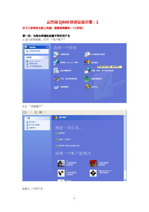
云终端Q600快速安装步骤:1 以下三步均在主机上完成,请按说明操作。
(三步法)第一步:为每台终端机创建不同的用户名1..进入控制面板,打开“用户帐户”2.点“创建帐户”3.输入一个用户名4.选择用户类型(XP系统选择计算机管理员账户)5.必须为用户创建密码(必须创建管理帐户,而且要设置一个密码,否则用此帐户不能进入系统。
不能创建受限帐户,受限帐户就是USER帐户。
因为受限帐户不能进入系统。
)按照上述方法,回到第1步为下一台终端机创建不同名称的新用户名和密码第二步:开启远程桌面并选择用户,把新建的用户添加到远程桌面。
在我的电脑上点鼠标右键,选择属性点远程把允许用户远程连接到此计算机,打上勾然后点击选择远程用户---添加高级—立即查找—选择你刚刚创建的用户确定第三步:安装软件3.1 安装光盘中的软件1.打开光盘,运行Nettc.exe,2.选择安装目录,如下图3.点击安装云终端Q600(新版)快速安装步骤:21.云终端Q600开机后默认的界面如下图:手动勾选“输入一个主机的名称或者IP地址”并在下列空白处输入主机的IP地址2.系统设置:可根据自己实际需要选择,也可以选择默认设置,不用任何更改。
①设置固定时间--------手动设置时间②同步服务器时间-----输入服务器IP可以同步时间(必须联网)③同步互联网-----------这里有多个选项,(建议选“3”必须联网)提示:设置好后务必多点击几次保存,以便成功保存刚才的设置。
3.登陆设置:主要设置分辨率。
这里可以设置分辨率,真彩色恢复出厂设置,远程连接之前请在这里把‘USB’选项打钩点击‘保存’4.网络设置:可根据实际情况来设置,默认是自动获取IP地址‘DHCP’路由器自动分配IP地址‘STATIC’手动输入IP地址5.更新设置:6.密码设置:使用最好不要用密码,如不得已,请记住您设置的密码,因为密码不能恢复7.点击开机画面中的‘本地应用’可以进入到以下界面点击“桌面模式”在这里也可以进行“远程桌面连接”点击远程桌面图标8.远程桌面连接输入主机IP地址,点连接输入您在服务器创建的用户名和密码,单机确定这里点击“是”如果以后不希望在提示此步骤,请在下框打钩这里就进入远程桌面了如果您进不去远程桌面:请检查:1.您的网络是否通畅的2.在服务器上创建用户名和密码的时候,密码不能为空3.是否安装了光盘里软件附件:Q600W无线网卡的设置:1.勾选:“输入一个主机的名称或者IP地址”并输入主机的IP地址,一定输入正确的IP地址,否则登陆不到主机,请务必认真核对。
Q530云终端安装使用
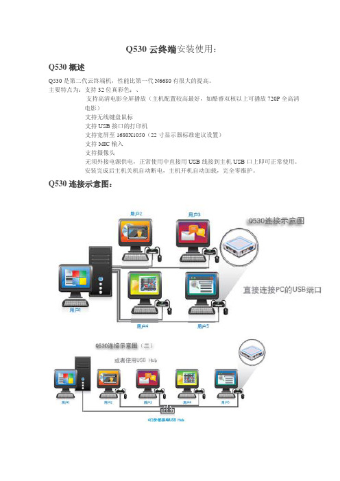
Q530云终端安装使用:Q530概述Q530是第二代云终端机,性能比第一代N6680有很大的提高。
主要特点为:支持32位真彩色;、支持高清电影全屏播放(主机配置较高最好,如酷睿双核以上可播放720P全高清电影)支持无线键盘鼠标支持USB接口的打印机支持宽屏至1680X1050(22寸显示器标准建议设置)支持MIC输入支持摄像头无须外接电源供电,正常使用中直接用USB线接到主机USB口上即可正常使用。
安装完成后主机关机自动断电,主机开机自动加载,完全零维护。
Q530连接示意图:Q530安装1,打开Q530安装盘软件目录见到如下2,先打开USBdriver目录双击setup.exe文件3,双击Setup.exe文件后将自动进行驱动安装,后面直接点击下一步下一步即可。
4,安装驱动完成后选择否,稍后重启动计算机如下图:5,安装完驱动程序就将Q530终端设备用USB打印线连接到主机的USB接口上,注意将开关拔到开的一边,就会看到终端的指示灯亮起,主机右下角会提示安装设备,安装时系统提示没有通过徽标测试,这是正常现象点击仍然继续即可,如下图:至此硬件驱动安装完成,然后打开管理软件安装目录MUPCS6,双击Setup.exe文件进行安装,后面也是下一步,不用更改任何设置,运行配置向导默认重启动时自动开始。
7,下一步后出现提示是否重启动计算机,选如下图8,系统重启动以后会终端机确认已经连接好键盘,鼠标,显示器并检查显示器是否有显示蓝色背景,如一切正常重启动后桌面也会有配置向导的提示:9.点击确定键。
主机和终端的各显示屏上就会依次显示没有内容的桌面,只出现一个提示用户按键盘的图标,如图:10.根据提示依次在有提示按键盘的终端上敲回车键,上面图示中有个有个鼠标并有一个红色禁止标志,表示不要按鼠标,并有提示按下回车键盘,配置时注意看显示屏上的提示就可以。
有的系统也会提示鼠标点击,(一般不会)则按提示操作即可。
操作完成后配置完成,确定系统自动重启动,工作站配置完成。
配网自动化终端DTU安装调试步骤ppt课件
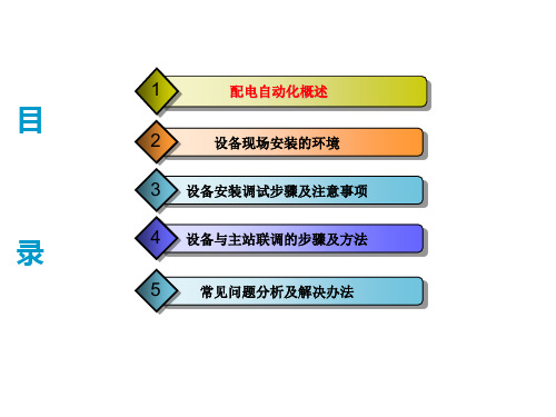
终端调试步骤
注意:当遥信位置信号和开关柜不对应时,首先,短接DTU 的遥信信号,查看DTU的遥信信号是否正常,不正常在排查 遥信接线及遥信板。DTU正常之后,在联系安装人员对开关 柜的遥信进行排查。
遥控:
在检查DTU的遥控没有短接之后,开关柜远方就地开关打到 远方位置,合上DTU的压板,在控制视图里对每一路的遥控 进行合分闸控制。同时也要对压板及远方就地开关进行检查, 在打开压板时远控失败,说明正常,在开关柜打到就地时远 控失败说明,远方就地开关接线正常。注意:在DTU进行控 制,但没有成功时,首先,要排查DTU遥控端有没有脉冲输 出,DTU脉冲输出遥控正常之后,然后在联系安装人员排查 开关柜的接线是否正常。
对DTU内 部的遥控、 遥信、遥 测线路进 行检查确 保DTU内 部三遥功 能正常。
对DTU内 部的遥控 进行检查 确保遥控 继电器接 点都是在 断开状态 。
终端调试步骤
(5)三遥调试 在调试三遥之前把调试软件打开,连接核心单元,把 需要的参数下发到核心单元里,开始调试三遥。 遥信: 送上操作电源、交流电源、当设备正常运行之后,打 开召测视图,选择遥信召测,对每一路的开关柜的合闸、 分闸、接线刀闸、远方/就地信号分别动作,查看软件 里的遥信变位信息是否和现场的开关位置一致。
光配在 DTU内部 的安装正 面示意图 。
硬件参考指南 HP Compaq t5135-t5530 瘦客户机 (1)

本文档包含的所有权信息受版权法保护。事 先未经 Hewlett-Packard Company 书面许 可,不得复印、复制本文档的任何部分或将 其翻译成其他语言。
硬件参考指南
商用 C
2007 年 9 月
文档部件号: 437853–AA2
关于本书
警告! 以这种方式出现的文字表示如果不按照指示操作,可能会造成人身伤害或带来生命危险。 注意: 以这种方式出现的文字表示如果不按照指示操作,可能会损坏设备或丢失信息。 注: 以这种方式出现的文字提供重要的补充信息。
vi
7 静电释放
ZHCN
v
防止静电损坏 ...................................................................................................................................... 23 接地方法 ............................................................................................................................................. 23
云终端安装指南

云终端安装指南云计算技术的快速发展为企业提供了更加灵活和高效的IT解决方案。
其中,云终端技术作为一种新型的计算终端方式,被广泛应用于各个行业。
本文将为您提供云终端安装指南,以帮助您更好地理解和使用云终端。
第一部分:云终端技术简介云终端技术是一种将计算资源集中部署在云端服务器上,并通过网络将计算结果传输回终端设备的技术。
它可以以硬件或软件的形式存在,可以提供更高的性能和更好的用户体验。
云终端技术的主要优势包括:1. 资源集中管理:云终端技术可以将计算资源集中管理,提高资源利用率,降低维护成本;2. 安全性提升:由于终端设备无法直接访问云端服务器,云终端技术可以提供更高的数据安全性;3. 跨平台支持:云终端技术可以在不同的终端设备上运行,支持跨平台使用。
第二部分:云终端安装指南1. 确认系统要求:在安装云终端之前,需要确认终端设备的系统要求,包括操作系统版本、硬件配置等信息。
根据设备的要求,选择适合的云终端软件。
2. 下载并安装云终端软件:根据设备的要求,从官方网站下载适用于您的设备的云终端软件。
确保下载软件是从官方渠道获取,以确保安全性。
3. 安装云终端软件:运行下载的安装程序,按照安装向导进行安装。
在安装过程中,可以根据自己的需要选择需要安装的组件和功能。
4. 配置云终端连接:安装完成后,打开云终端软件,进行配置。
填写云终端服务器的地址和账号信息,然后保存配置。
5. 连接云终端服务器:在配置完成后,点击连接按钮,云终端软件将会尝试连接云终端服务器。
如果连接成功,您将能够使用云终端进行计算任务。
6. 使用云终端功能:一旦连接成功,您可以根据软件的功能和界面来进行各种操作,如文件传输、远程控制等。
根据具体的软件和需求,进行任务操作。
第三部分:云终端的使用场景云终端技术可以应用于多个领域,如金融、医疗、教育等。
以下是一些常见的使用场景:1. 远程办公:云终端技术可以帮助用户实现远程办公,无论在任何地点和时间,都可以访问云终端服务器进行办公任务,提高工作效率。
拖机盒

拖机盒,电脑一拖多,电脑云终端,Net5530电脑一变多只花几百元,就能够买一台电脑?可能听上去有些离奇,那现在要介绍的这款新鲜设备肯定让你大开眼界。
它不光是一台电脑,而且更重要的是它体积十分小巧,比一个路由器都要小,主要的应用场景是一些空间紧缺的公司,有了这个小东西,再配上显示器、鼠标键盘,就可以当作一台真正的电脑使用了。
最大可带台数 30台距离限 无距离限制是否插卡 无需插卡连接方式 网线连接支持系统 windows 2000 专业版、 windows xp 家庭版、 windows xp 专业版、windows xp 媒体中心版、 windows 2000 服务器版、windows 2003 服务器支持电影 不支持支持USB1.1存储 无远程访问 可远程访问色彩范围 16真色支持分辨率640*480 ,800*600 ,1024*768(60HZ或75HZ),1280*1024(63HZ),产品核心优势避免企业大量淘汰电脑和减少过重的维护问题,彻底做到省心、省事还省钱。
这就是一款来来自高科技的产品,下文简称网络式终端。
这是一种最时髦的企业解决方案,可以把成本控制到最少,而且组建的系统易于升级,只需要更换服务器,任何一台网络式终端都可以得到性能的提升。
那么这到底是怎么回事呢?先来看看此款产品的可以实现的功能。
这款产品可以通过局域网来虚拟一台电脑,一台服务器可以带30台这样的设备,而每一台插上显示器与键鼠就可以正常使用了。
节省空间、节省电力、减少设备成本,让办公环境变得井井有条,别看它小,这些都是它可以解决的产品体积十分小,只有手掌那么大,但是什么都不缺,电脑的一切接口都有,我们先从外观上分析分析。
产品外观风格很低调,给人沉稳的感觉,做工十分精致,确属大厂产品。
前面板也十分抢眼,有三个指示灯,电源、网络与工作状态。
NETSTATION5530可以选配支架,放在液晶显示器后面,支架单行购买,不在产品配套之中看产品的侧面,鼠标接口、键盘接口、音频、一样都不缺。
云终端安装实施方案

云终端安装实施方案一、前言。
随着云计算技术的不断发展和普及,云终端作为一种新型的终端设备,正在逐渐成为企业办公和生产环境中的重要组成部分。
为了更好地帮助用户实施云终端的安装工作,本文将详细介绍云终端安装的实施方案,旨在为用户提供一套完整、系统的操作指南,帮助用户顺利完成云终端的安装工作。
二、准备工作。
在进行云终端安装之前,需要做好以下准备工作:1. 确定云终端安装的位置和数量,根据实际情况选择合适的安装方案。
2. 确保所需的云终端设备已经购买并到货,检查设备是否完好无损。
3. 准备好安装所需的工具和材料,包括螺丝刀、螺丝、电源线等。
4. 确保安装现场的网络环境和电源环境已经准备就绪,确保云终端设备可以正常接入网络和供电。
5. 对于大型企业或特殊环境,可能需要提前进行现场勘测和方案设计。
三、安装步骤。
1. 安装前的准备工作。
(1)根据实际情况选择合适的安装位置,确保位置的稳固和安全。
(2)将云终端设备放置在预定的安装位置上,检查设备是否完好无损。
(3)连接好设备所需的电源线和网络线,确保设备可以正常供电和接入网络。
2. 设备固定安装。
(1)使用螺丝刀将云终端设备固定在安装位置上,确保设备稳固牢固。
(2)对于大型设备或特殊环境,可能需要进行专业的设备安装。
3. 网络配置。
(1)根据实际情况配置设备的网络参数,确保设备可以正常接入网络。
(2)进行网络连接测试,确保设备可以正常访问云服务和其他网络资源。
4. 系统初始化。
(1)按照设备使用说明书的指引,进行设备的系统初始化操作。
(2)进行系统功能测试,确保设备的各项功能正常。
四、收尾工作。
1. 清理现场。
安装完成后,对安装现场进行清理,清除安装过程中产生的杂物和垃圾。
2. 验收测试。
对安装的云终端设备进行验收测试,确保设备安装和配置的正常运行。
3. 记录备份。
对安装过程中的关键操作和参数进行记录备份,以备日后维护和管理。
五、总结。
通过本文的介绍,相信大家已经对云终端的安装实施方案有了更加清晰的认识。
Moxa EDS-G500E系列快速安装指南说明书

P/N: 1802005000023 *1802005000023*EDS-G500E Series Quick Installation GuideMoxa EtherDevice™ SwitchVersion 3.1, September 2020Technical Support Contact Information/supportMoxa Americas:Toll-free: 1-888-669-2872 Tel: 1-714-528-6777 Fax: 1-714-528-6778 Moxa China (Shanghai office): Toll-free: 800-820-5036 Tel: +86-21-5258-9955 Fax: +86-21-5258-5505 Moxa Europe:Tel: +49-89-3 70 03 99-0 Fax: +49-89-3 70 03 99-99 Moxa Asia-Pacific:Tel: +886-2-8919-1230 Fax: +886-2-8919-1231 Moxa India:Tel: +91-80-4172-9088 Fax: +91-80-4132-10452020 Moxa Inc. All rights reserved.Package ChecklistThe EDS-G500E is shipped with the following items. If any of these items are missing or damaged, please contact your customer service representative for assistance.• 1 EDS-G508E or EDS-G512E-4GSFP or EDS-G516E-4GSFP Ethernet switch•Quick installation guide (printed)•Warranty card•USB cable•Protective caps for unused portsFeatures•Up to 12 10/100/1000BaseT(X) ports and 4 100/1000BaseSFP ports•Turbo Ring and Turbo Chain (recovery time < 50 ms @ 250 switches), RSTP/STP, and MSTP for network redundancy •RADIUS, TACACS+, SNMPv3, IEEE 802.1x, HTTPS, and SSH to enhance network security•EtherNet/IP, PROFINET, and Modbus/TCP protocols supported for device management and monitoringPanel Views of EDS-G500E SeriesFront PanelEDS-G508EEDS-G512E-4GSFPFront Panel1. 1000BaseT(X) LED indicator2. 10/100BaseT(X) LED indicator3. 10/100/1000BaseT(X) portsEDS-G508E: 1 to 8EDS-G512E-4GSFP: 1 to 8 EDS-G516E-4GSFP: 1 to 12 4. System status LED:• STATE LED indicator • PWR1 LED indicator • PWR2 LED indicator • FAULT LED indicator• MSTR/HEAD LED indicator • CPLR/TAIL LED indicator 5. USB storage port6. SFP port LED indicatorEDS-G512E-4GSFP: 9 to 12 EDS-G516E-4GSFP: 13 to 16 7. 100/1000BaseSFP slots 8. Model NameEDS-G516E-4GSFPTop Panel Rear Panel Top Panel1.Reset buttonB console port3.DIP switches for Turbo Ring,Ring Master, and Ring Coupler4.Grounding screw5.4-pin terminal block for digitalinput and power input 26.4-pin terminal block for relayoutput and power input 1 Rear Panel1.Screw holes for wall mountingkit2.DIN-rail mounting kitMounting DimensionsUnit = mm (inch)DIN-Rail MountingThe metal DIN-rail kit is fixed to the back panel of the EDS-G500E series when you take it out of the box. Mount the EDS-G500E series on corrosion-free mounting rails that meet the EN 60715 standard. InstallationSTEP 1: Insert the upper lip of the DIN rail into the DIN-rail mounting kit.STEP 2: Press the EDS-G500E series towards the DIN rail until it snaps into place.RemovalSTEP 1: Pull down the latch on the mounting kit with a screwdriver. STEP 2 & 3: Slightly pull the EDS-G500E series forward and lift up to remove it from the DIN rail.Wall Mounting (Optional)For some applications, you will find it convenient to mount Moxa EDS- G500E series on the wall, as shown in the following illustrations: STEP 1: Remove the aluminum DIN railattachment plate from the rear panel of the EDS-G500E series, and then attach the wall mount plates with M3 screws, as shown in the figure at the right.STEP 2: Mounting the EDS-G500E series on the wall requires 4 screws. Use the EDS-G500E series, with wall mount plates attached, as a guide to mark the correct locations of the 4 screws. The heads of the screws should be less than 6.0 mm in diameter, and the shafts should be less than 3.5 mm in diameter, as shown in the figure on at right.NOTE Before tightening the screws into the wall, make sure the screw head and shank size are suitable by inserting the screw through one of the keyhole-shaped apertures of the Wall Mounting Plates.Do not screw the screws in all the way—leave about 2 mm to allowroom for sliding the wall mount panel between the wall and the screws. STEP 3: Once the screws are fixed to the wall, insert the four screw heads through the wide parts of the keyhole-shaped apertures, and then slide the EDS-G500Edownwards, as indicated in the figure at the right.Tighten the four screws for more stability.ATEX Information1. Certificate number: DEMKO 14 ATEX 1212X2. Certification string: Ex nA nC IIC T4 Gc3. Standards covered:EN 60079-0:2012+A11:2013, EN 60079-15:20104. These products are to be installed in an ATEX Certified IP54enclosure and accessible only by the use of a tool.5. These products are for use in an area of not more than pollutiondegree 2 in accordance with IEC 60664-1.Wiring RequirementsPlease read and follow these guidelines: •Use separate paths to route wiring for power and devices. If power wiring and device wiring paths must cross, make sure the wires are perpendicular at the intersection point.NOTE: Do not run signal or communications wiring and powerwiring through the same wire conduit. To avoid interference, wires with different signal characteristics should be routed separately •You can use the type of signal transmitted through a wire todetermine which wires should be kept separate. The rule of thumb is that wiring that shares similar electrical characteristics can be bundled together• You should separate input wiring from output wiring•We advise that you label the wiring to all devices in the system.Grounding the Moxa EDS-G500E SeriesGrounding and wire routing help limit the effects of noise due toelectromagnetic interference (EMI). Run the ground connection from the ground screw to the grounding surface prior to connecting devices.Wiring the Relay ContactThe EDS-G500E series has one set of relay output. This relay contact uses two contacts of the terminal block on the EDS-G500E’s top panel. Refer to the next section for detailed instructions on how to connect the wires to the terminal block connector, and how to attach the terminal block connector to the terminal block receptor. In this section, we illustrate the meaning of the two contacts used to connect the relay contact.FAULT: Array The two contacts of the 6-pin terminal block connector are used to detect user-configured events. The two wires attached to the fault contacts form an open circuit when a user-configured event is triggered. If a user-configured event does not occur, the fault circuit remainsclosed.Wiring the Redundant Power InputsThe EDS-G500E series has two sets of power inputs—power input 1 and power input 2. The top and front views of one of the terminal block connectors are shown here.STEP 1: Insert the negative/positiveDC wires into the V-/V+ terminals,respectively. STEP 2: To keep the DC wires frompulling loose, use a small flat-bladescrewdriver to tighten the wire-clamp screws on the front of the terminalblock connector. STEP 3: Insert the plastic terminalblock connector prongs into theterminal block receptor, which islocated on the EDS-G500E’s toppanel.Wiring the Digital InputsThe EDS-G500E series has one set of digital input (DI). The DI consists of two contacts of the 4-pin terminal block connector on the EDS-G500E's top panel, which are used for the two DC inputs. The top and front views of one of the terminal block connectors are shown here.STEP 1: Insert the negative(ground)/positive DI wires into the┴/I terminals, respectively.STEP 2: To keep the DI wires frompulling loose, use a small flat-bladescrewdriver to tighten the wire-clampscrews on the front of the terminalblock connector. STEP 3: Insert the plastic terminalblock connector prongs into theterminal block receptor, which islocated on the EDS-G500E’s toppanel.Communication ConnectionsEach EDS-G500E series switch has 4 types of communication ports: •1 USB console port (type B connector) •1 USB storage port (type A connector) •8 (EDS-G508E/EDS-G512E-4GSFP) or 12 (EDS-G516E-4GSFP) 10/100/1000BaseT(X) Ethernet ports • 4 100/1000Base SFP slots (EDS-G512E-4GSFP/EDS-G516E-4GSFP) USB Console ConnectionThe EDS-G500E series has one USB console port (type B connector), located on the top panel. Use the USB cable (provided in the product package) to connect the EDS-G500E's console port to your PC's USB port and install the USB driver on the PC. You may then use a console terminal program, such as Moxa PComm Terminal Emulator, to accessthe EDS-G500E’s console configuration utility.USB Console Port (Type B Connector) PinoutsPinDescription 1D– (Data -) 2VCC (+5V) 3D+ (Data+) 4 GND (Ground) USB Storage ConnectionThe EDS-G500E series has one USB storage port (type A connector) on the front panel. Use Moxa ABC-02-USB-T automatic backupconfigurator to connect the EDS-G500E's USB storage port forconfiguration backup, firmware upgrade or system log file backup. ABC-02-USB InstallationPlug the ABC-02-USB into the USBstorage port of the Moxa EDS-G500Eseries. Securing the ABC-02-USB on thewall with an M4 screw is suggested.USB Storage Port (Type A Connector) PinoutsPinDescription 1VCC (+5V) 2D– (Data -) 3D+ (Data+) 4 GND (Ground) 1000BaseT Ethernet Port Connection1000BaseT data is transmitted on differential TRD+/- signal pairs over copper wires.MDI/MDI-X Port Pinouts PinSignal 1TRD(0)+ 2TRD(0)- 3TRD(1)+ 4TRD(2)+ 5TRD(2)- 6TRD(1)- 7TRD(3)+ 8 TRD(3)-100/1000BaseSFP (mini-GBIC) Fiber PortThe Gigabit Ethernet ports on the EDS-G500E series are100/1000BaseSFP Fiber ports, which require using the 100M or 1G mini-GBIC fiber transceivers to work properly. Moxa provides completed transceiver models for different distance requirement.The concept behind the LC port and cable is quite straightforward. Suppose that you are connecting devices I and II; contrary to electrical signals, optical signals do not require a circuit in order to transmit data. Consequently, one of the optical lines is used to transmit data from device I to device II, and the other optical line is used transmit data from device II to device I, for full-duplex transmission.Remember to connect the Tx (transmit) port of device I to the Rx (receive) port of device II, and the Rx (receive) port of device I to the Tx (transmit) port of device II. If you make your own cable, we suggest labeling the two sides of the same line with the same letter (A-to-A and B-to-B, as shown below, or A1-to-A2 and B1-to-B2).LC-Port Pinouts LC-Port to LC-Port Cable WiringReset ButtonThere are two functions available on the Reset Button. One is to reset the Ethernet switch to factory default settings by pressing and holding the Reset button for 5 seconds. Use a pointed object, such as a straightened paper clip or toothpick, to depress the Reset button. This will cause the STATE LED to blink once a second. After depressing the button for 5 continuous seconds, the STATE LED will start to blink rapidly. This indicates that factory default settings have been loaded and you can release the reset button.When the ABC-02-USB is connected to the EDS-G500E Ethernet switch,the reset button allows quick configuration and backs up log files to theABC-02-USB. Press the Reset button on top of the EDS-G500E, theEthernet switch will start backing up current system configuration filesand event logs to the ABC-02-USB.NOTE Do NOT power off the Ethernet switch when loading defaultsettings.Turbo Ring DIP Switch SettingsEDS-G500E series are plug-and-play managed redundant Ethernet switches. The proprietary Turbo Ring protocol was developed by Moxa to provide better network reliability and faster recovery time. Moxa Turbo Ring’s recovery time is less than 300 ms (Turbo Ring) or 50 ms (Turbo Ring V2) —compared to a 3- to 5-minute recovery time for commercial switches—decreasing the possible loss caused by network failures in an industrial setting.There are 4 Hardware DIP Switches for Turbo Ring on the top panel of EDS-G500E series that can help setup the Turbo Ring easily within seconds. If you do not want to use a hardware DIP switch to setup the Turbo Ring, you can use a web browser, telnet, or console to disable this function.NOTE Please refer to the Turbo Ring section in Communication Redundancy User's Manual for more detail information aboutthe setting and usage of Turbo Ring and Turbo Ring V2. EDS-G500E Series DIP Switches Array The default setting for each DIP Switch is OFF. Thefollowing table explains the effect of setting the DIPSwitch to the ON position.NOTE You must enable the Turbo Ring function first before using the DIP switch to activate the Master and Coupler functions. NOTE If you do not enable any of the EDS-G500E series switches to be the Ring Master, the Turbo Ring protocol will automaticallychoose the EDS-G500E series with the smallest MAC addressrange to be the Ring Master. If you accidentally enable morethan one EDS-G500E series to be the Ring Master, these EDS-G500E series switches will auto-negotiate to determine whichone will be the Ring Master.LED IndicatorsThe front panel of the Moxa EDS-G500E series contains several LED indicators. The function of each LED is described in the following table: LED Color Status DescriptionSTATE GreenOnThe system passed the self-diagnosis teston boot-up and is ready to run.Blinking1.The switch is under reset progress (1time/s).2.Detect ABC-02-USB connect to theswitch (1 time/2s).Red OnThe system failed self-diagnosis on boot-up.•RAM Test Fail / System Info. Read Fail/ Switch Initial Fail / PTP PHY Error.(+ Green MSTR lit on : HW FAIL)•FW Checksum Fail / Uncompress Fail.(+ Green Coupler lit on: SW FAIL)FAULT Red On 1.The signal contact is open.2.ABC Loading/Saving Fail.3.The port being disabled because ofthe ingress multicast and broadcastpackets exceed the ingress rate limit.4.Incorrect loop connection in a singleswitch.5.Invalid Ring port connection.PWR1 Amber OnPower is being supplied to the mainmodule’s power input PWR1.OffPower is not being supplied to the mainmodule’s power input PWR1.PWR2 Amber OnPower is being supplied to the mainmodule’s power input PWR2.OffPower is not being supplied to the mainmodule’s power input PWR2.LED Color Status DescriptionMSTR/ HEAD GreenOn1.The switch is set as the Master of theTurbo Ring, as the Head of the TurboChain, or as the Root bridge of RSTP.2.POST H.W. Fail (+Stat on and Faultblinking).Blinking1.The switch has become the RingMaster of the Turbo Ring.2.The Head of the Turbo Chain, afterthe Turbo Ring or the Turbo Chain isdown.3.The switch is set as Turbo Chain’sMember and the corresponding chainport is down.Off1.The switch is not the Master of thisTurbo Ring.2.This switch is set as a Member of theTurbo Chain.CPLR/TAIL GreenOn1.The switch’s coupling function isenabled to form a back-up path.2.When it’s set as the Tail of the TurboChain.3.POST S.W. Fail (+Stat on and Faultblinking)Blinking1.Turbo Chain is down.2.The switch is set as Turbo Chain’sMember and the corresponding chainport is down.Off1.This switch has disabled the couplingfunction.2.This switch is set as a Member of theTurbo Chain.FAULT + MSTR/HEAD + CPLR/TAILRotateBlinkingSequentiallyABC-02-USB is importing/exporting files.STATE +FAULT + MSTR/HEAD + CPLR/TAIL BlinkingSwitch is being discovered/located byMXview (2 times/s).10M/100M (TP) AmberOn TP port’s 10 or 100 Mbps link is active.BlinkingData is being transmitted at 10 or 100Mbps.Off TP port’s 10/100 Mbps link is inactive.1000M (TP) GreenOn TP port’s 1000 Mbps link is active. Blinking Data is being transmitted at 1000 Mbps. Off TP port’s 1000 Mbps link is inactive.100M (SFP) AmberOn SFP port’s 100 Mbps link is active. Blinking Data is being transmitted at 100 Mbps. Off SFP port’s 100 Mbps link is inactive.1000M (SFP) GreenOn SFP port’s 1000 Mbps link is active. Blinking Data is being transmitted at 1000 Mbps. Off SFP port’s 1000 Mbps link is inactive.SpecificationsTechnologyStandards IEEE 802.3 for 10BaseTIEEE 802.3u for 100BaseT(X) and 100BaseFXIEEE 802.3ab for 1000BaseT(X)IEEE 802.3z for 1000BaseXProtocols IGMPv1/v2/v3, GMRP, GVRP, SNMPv1/v2c/v3,DHCP Server/Client, DHCP Option 66/67/82, BootP,TFTP, SNTP, SMTP, RARP, RMON, HTTP, HTTPS,Telnet, SSH, Syslog, EtherNet/IP, PROFINET,Modbus/TCP, SNMP Inform, LLDP, IEEE 1588 PTPV2, IPv6, NTP Server/ClientMIB MIB-II, Ethernet-Like MIB, P-BRIDGE MIB, Q-BRIDGE MIB, Bridge MIB, RSTP MIB, RMON MIBGroup 1, 2, 3, 9Flow Control IEEE 802.3x flow control, back pressure flowcontrolInterfaceRJ45 Ports 8 (EDS-G508E/EDS-G512E-4GSFP) or12 (EDS-G516E-4GSFP) 10/100/1000BaseT(X) Fiber Ports 4-port 100/1000BaseSFP slot (EDS-G512E-4GSFP/EDS-G516-4GSFP only)USB Ports USB console port (type B connector)USB storage port (type A connector)Button Reset buttonLED Indicators PWR1, PWR2, FAULT, STATE, 10/100M,100/1000M, MSTR/HEAD, CPLR/TAILAlarm Contact 1 relay output with current carrying capacity of 1 A@ 24 VDCDigital Input 1 input with the same ground, but electricallyisolated from the electronics.•+13 to +30V for state “1”•-30 to +3V for state “0”•Max. input current: 8 mAPowerInput Voltage 12/24/48/-48 VDC, redundant dual inputsInput Current EDS-G516E: 0.46 A @ 24 VDCEDS-G512E: 0.4 A @ 24 VDCEDS-G508E: 0.33 A @ 24 VDCConnection 2 removable 4-contact terminal blocksOverload CurrentPresentProtectionPresentReverse PolarityProtectionPhysical CharacteristicsHousing Metal, IP30 protectionDimension 79.2 x 135 x 137 mm (3.1 x 5.3 x 5.4 in) Installation DIN-rail mounting, wall mounting (with optionalkit)Environmental LimitsOperating Temperature -10 to 60°C (14 to 140°F) for standard models -40 to 75°C (-40 to 167°F) for -T modelsStorageTemperature-40 to 85°C (-40 to 185°F)Ambient RelativeHumidity5 to 95% (non-condensing)Altitude Up to 2000 mNote: Please contact Moxa if you require products guaranteed to function properly at higher altitude.Regulatory ApprovalsSafety UL 508EMI FCC Part 15 Subpart B Class A, EN 55022 Class A EMS EN 61000-4-2 (ESD) Level 4,EN 61000-4-3 (RS) Level 3,EN 61000-4-4 (EFT) Level 4,EN 61000-4-5 (Surge) Level 4,EN 61000-4-6 (CS) Level 3,EN 61000-4-8Shock IEC 60068-2-27Free Fall IEC 60068-2-32Vibration IEC 60068-2-6WarrantyWarranty 5 years。
西门子产品说明书:FT2014 FT2015远程显示器 远程终端安装及安装方法
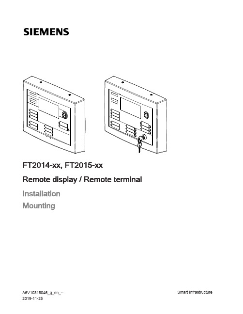
FT2014-xx, FT2015-xxRemote display / Remote terminalInstallationMountingA6V10315046_g_en_--Smart Infrastructure 2019-11-25Legal noticeLegal noticeTechnical specifications and availability subject to change without notice.Transmittal, reproduction, dissemination and/or editing of this document as well asutilization of its contents and communication thereof to others without expressauthorization are prohibited. Offenders will be held liable for payment of damages. Allrights created by patent grant or registration of a utility model or design patent arereserved.Issued by:Siemens Industry, Inc.Smart Infrastructure8 Fernwood RoadFlorham Park, NJ 07932Tel. +1 973-593-2600/FISEdition: 2019-11-25Document ID: A6V10315046_g_en_--A5Q00049958© Siemens Industry, Inc., 20162 | 16A6V10315046_g_en_--Table of contents1Remote display FT2014 / remote terminal FT2015 (5)1.1Description (5)1.2Mounting (6)1.3Views (7)1.3.1back box (7)1.3.2View of printed circuit board (9)1.4Wiring (9)1.4.1X5/X6, RS485 circuit connection terminals (10)1.4.2X11, connection for key switch and ground cable (11)1.5Adjustment elements (12)1.6Technical data (13)2FCC Statement (15)A6V10315046_g_en_-- 3 | 164 | 16A6V10315046_g_en_--1Remote display FT2014 / remote terminalFT2015Figure 1: Remote display FT2014 (left) and remote terminal FT2015 (right)1.1DescriptionFT2014 and FT2015 are synchronized with 'Panels' of the configured visibility and display the same event texts. The two devices are connected to the control panel via the RS485 circuit.The remote display and the remote terminal are available in the following versions:●FT2014 remote display (red)●FT2014 remote display (black)●FT2015 remote terminal (red)●FT2015 remote terminal (black)Common features●Connection to the RS485 circuit as class A or class B●Power supply from the associated fire control panel or fire voice control panel ●External supply possible●8-line display each with 40 characters per line and backlight ●Buzzer●Operation enabled by key switch ●Indication of alarms and troubles ●Bypass for installed buzzer●Three LEDs configurable with the engineering tool set ●Inscription strips for sliding inAdditional features of the remote terminal FT2015●Acknowledgement and resetting of alarms and troubles ●Three buttons configurable with the engineering tool setRemote display FT2014 / remote terminal FT2015Description1A6V10315046_g_en_-- 5 | 16Document referencesThe templates for the inscription strips and the operating instructions with button and LED designations have the following document IDs:1.2MountingMounting is identical for FT2014 and FT2015.Figure 2: Mounting view taking example of FT20151Housing22x fixing screw on the top part of the housing 3back box43x slot for cable tie52x threaded hole for fixing screws 68x fixing slot for wall mountingRemote display FT2014 / remote terminal FT2015Mounting16 | 16A6V10315046_g_en_--7Cable entry82x holder cam for housingMounting1.Loosen the fixing screws (2) on the top part of the housing and remove thehousing (1) from the back box (3) by tilting it forward and pulling it down.2.Position the back box such that the cables can be led correctly through the cableentry (7). Mark the fixing slots (6) in this position.3.Drill the holes and secure the back box (3) to the wall by inserting dowel screwsthrough the fixing slots (6).4.Wire up the device according to the wiring diagram.5.Fix the cables to the slots (4) with cable ties and mount the housing on the backbox by following step 1 in reverse.See also2Wiring [➙ 9]2back box [➙ 7]1.3Views1.3.1back boxDimension drawing for the back boxFigure 3: Dimensions of the back box of the FT2014 and FT2015, view from insideRemote display FT2014 / remote terminal FT2015Views1A6V10315046_g_en_--7 | 16Detail 1: Dimensions of the fixing slotsFigure 4: Detailed view of the fixing slotsDimension tableRemote display FT2014 / remote terminal FT2015Views18 | 16A6V10315046_g_en_--1.3.2View of printed circuit boardFigure 5: Printed circuit board view of remote display and remote terminal1.4WiringThe circuit must not be terminated on the side of the RS485 class A module, because the RS485 class A module has integrated terminating resistors.When wiring as a class B circuit, the circuit on the last device must be terminated with a 120 Ω resistor.Remote display FT2014 / remote terminal FT2015Wiring1A6V10315046_g_en_--9 | 16Wiring from the remote display and remote terminal to the RS485 circuit as a class B circuitFigure 6: FT2014/FT2015 class B wiringWiring from the remote display and remote terminal to the RS485 circuit as a class A circuitFigure 7: FT2014/FT2015 class A wiring1.4.1X5/X6, RS485 circuit connection terminalsPlug X6, NET_INRemote display FT2014 / remote terminal FT2015Wiring110 | 16A6V10315046_g_en_--Plug X5, NET_OUT1.4.2X11, connection for key switch and ground cableFigure 8: Wiring of the key switch and ground cable1Key switch T452Ground connection on back box3Ground cable, pre-configured, l = 13.7"/350 mm 4Grounding washer with plug connection 5Screwed connections for cable lug6Cable for key switch, pre-configured, l = 3.55"/90 mmRemote display FT2014 / remote terminal FT2015Wiring1A6V10315046_g_en_--11 | 16X11Connection for key switch connection cable1.Connect the pre-configured ground cable (3) by inserting the flat connector into theplug connection of the grounding washer (4)ing a washer and nut, screw the cable lug at the other end of the ground cable(3) onto the threaded bolt in the back box (2) so that it is secure.3.Tighten both cable lugs of the key switch cable (6) at the contacts (5) of the keyswitch (1).4.Plug the other end of the key switch cable (6) into connector X11 on the printedcircuit board.1.5Adjustment elementsReset key S2The reset key S2 has two functions:●Restart the processor to trigger the watchdog●Read-in the set baud rate and address with DIP switch S1DIP switch S1All switches are set to the OFF position (right-hand position) at the factory.PWR_F SW_REV 01BAUD4812ADR Figure 9: View of DIP switch S1 with inscriptionRemote display FT2014 / remote terminal FT2015Adjustment elements112 | 16A6V10315046_g_en_--Setting the device addressSetting the baud rateFor each RS485 class A module (isolated), remote display FT2014 and remote terminal FT2015 can only be operated in the following combination:●FT201x with baud rate setting 9600 only together with the FT2003 graphic driver (I/O) (fixed baud rate of 9600)●FT201x with baud rate setting 9600 only together with the FCA2018 remoteperipheral module (fixed baud rate of 19200)1.6Technical dataSupplyDesignation '+', '–'Voltage V sys DC 24 V Wattage55 mARS485 circuitTerminals Plug-in terminals Circuit voltageDC 4…5 V Transmission rate adjustable ●9.6 kbit/s ●19.2 kbit/sNumber of participantsMax. 8Remote display FT2014 / remote terminal FT2015Technical data1A6V10315046_g_en_--13 | 16Length of line Class B ●Max. 3940 ft / 1200 m with AWG14 at 19.2 kbit/s●Max. 3300 ft / 1005 m with AWG18 at 19.2 kbit/sClass AMax. 3300 ft / 1005 m including the return lineFunctional dataDisplayLCD256 x 112 pixels8 lines of 40 characters each Acoustic signalingTone interval can be configured with engineering tool set DimensionsHeight 9.27 in/235.5 mm Width12.58 in/319.5 mm Depth (incl. back box)2.4 in/61 mmAmbient conditionsOperating temperature 32...120 °F / -0…+49 °C Storage temperature -4...+140 °F / -20…+60 °CMax. application height 13,100 ft. above sea level / 3993 m above sea level StandardsUL 864Remote display FT2014 / remote terminal FT2015Technical data114 | 16A6V10315046_g_en_--FCC Statement2 2FCC StatementThis equipment generates, uses, and can radiate radio frequency energy and if notinstalled and used in accordance with the instructions manual, may cause interferenceto radio communications.It has been tested and found to comply with the limits for a Class A computing devicepursuant to Part 15 of FCC Rules, which are designed to provide reasonable protectionagainst such interference when operated in a commercial environment.Operation of this equipment in a residential area is likely to cause interference in whichcase the user at his own expense will be required to take whatever measures may berequired to correct the interference.A6V10315046_g_en_--15 | 16Issued bySiemens Industry, Inc. Smart Infrastructure8 Fernwood Road Florham Park, NJ 07932 +1 973-593-2600/FIS A6V10315046_g_en_--© Siemens Industry, Inc., 2016 Technical specifications and availability subject to change without notice.。
Moxa MD-215系列快速安装指南说明书

P/N: 1802002150011 *1802002150011*MD-215 SeriesQuick Installation GuideVersion 1.1, January 2021Technical Support Contact Information/support2021 Moxa Inc. All rights reserved.OverviewThe MD-215 is a 15-inch industrial display with an aspect ratio of 5:4. It is a reliable and durable display of wide versatility of use in industrial environments.The MD-215 series displays are designed with a wide -40 to 70°C temperature range, making them some of the most reliable industrial platforms available for harsh, hot, indoor/outdoor environments.The MD-215 also features a 1,000-nit LCD panel offering asunlight-readable, projected-capacitive, glove-friendly, multi-touch screen, providing an excellent user experience for outdoor applications. Package ChecklistBefore installing the MD-215 Series, verify that the package contains the following items:•MD-215 display•VGA cable•DVI-D cable•2-pin terminal block x 1•5-pin terminal block x 2•Quick installation guide (printed)•Warranty cardNOTE: Please notify your sales representative if any of the above items are missing or damaged.Hardware InstallationAppearanceSavvyTouch Display Control ButtonsThe SavvyTouch display controls are located on the front panel of the MD-215. These intelligent controls light up in response to a simple wave of the hand over the area of the screen where they are located. Thefollowing table describes the function of each SavvyTouch display control button:NameDisplayColorControl Function/Color LegendMenu/PowerGreenDisplay is powered on and functioning normally.Touch the button to show the OSDsettings menu.RedNo input signal detected. Display onstandby.Off Power is down and the display is off.Brightness WhiteUse this button to increase brightness of panel.Use this button to decrease brightness of panelName DisplayColorControl Function/Color LegendINFO Off AC/DC power functioning normally. Red AC/DC power error.Display mode WhiteSwitch between DAY/DUSK/NIGHTbrightness modes.OffPanel brightness outside the defaultrange.Installing the MD-215Panel MountingThe MD-215 comes with 8 optional clamp mounts for installation on a panel (where space has been cut out to accommodate the rest of the hardware) or into computing stations where a flush mount is required. The maximum thickness of the surface to which the display will be clamped is 11 mm. For a secure mounting, all 8 clamps must be used. The clamp arms are fastened into slots on all four sides of the MD-215. Use the short M4 SUS screws to fasten the clamp arms to the MD-215 mounting slots, as shown in the magnified inset in the diagram. Next, use the clamps to fasten the display to its mounting point. Note the torque value shown in the inset.VESA MountingThe MD-215 also comes with an optional VESA mounting kit. Four flat screws and four round screws are required to fasten the VESA mounting bracket. See the figure below for detailed screw specifications and torque values.An additional four screws (not included in the kit) are required to mount the display on a VESA rack. Use M6 screws with a length between 10 and 12 mm for this purpose.Connector DescriptionExtending the DisplayThe MD-215 is provided with both standard VGA and DVI-D interfaces on the bottom panel. The MD-215 can automatically detect whether the input video source is from the VGA or DVI-D interface. Configuring the Display via the Serial PortThe MD-215 has two serial ports. The RS-232 port uses a DB9 connector, and the RS-422/485 port uses a terminal block connector. Either serial port can be used to modify the display parameters using UART commands. For details on serial port configuration, refer to the MD-215 Hardware User’s Manual . The pin assignments for the ports are shown in the following table: Pin RS-232 1 DCD 2 RxD 3 TxD 4 DTR 5 GND 6 DSR 7 RTS 8CTSPinRS-422 RS-485 (2-wire)1 RxDB(+) TDp(+)2 RxDA(-) TDn(-)3 TxDB(+) RDp(+)4 TxDA(-) RDn(-) 5GNDGNDPowering On/Off the MD-215To power on the MD-215, connect the MD-215 to an AC power source, a DC power source, or both. Touch the Menu/power button for 1 second to turn on the display.Touch the Menu/power button for 4 seconds to turn off the display. NOTE If only one power input is connected, the Info button will turn red.This will however not affect the functionality and performance ofthe MD-215 as long as the power input is stable.Grounding the MD-215Proper grounding and wire routing help to limit the effects of noise from electromagnetic interference (EMI). Run the ground connection from the ground screw to the grounding surface prior to connecting the power source.For detailed configuration of the MD-215, refer to the MD-215 Hardware User’s Manual.。
6.云终端推广.笔记本安装说明
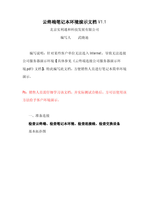
云终端笔记本环境演示文档V1.1北京实利通和科技发展有限公司编写人武晓迪编写说明:针对某些客户单位无法连入Internet,导致无法连接公司服务器演示环境【具体参见《云终端连接公司服务器演示环境.pdf》文档】,特此编写此文档,方便销售人员进行笔记本简单环境演示。
Ps:销售人员需仔细学习该文档,并实际测试合格后,方可以使用该方法给予客户环境演示。
一、准备连接检查云终端、检查笔记本环境、检查连接线、检查交换设备基本拓扑图检查云终端固件检查云终端设备,说明书,质保卡,安装光盘,显示器挂架,电源,螺丝钉是否齐全。
检查云终端设备是否洁净,云终端设备/电源接口是否有损坏,光盘是否有损坏。
检查网线是否完好检查网线线缆是否完好,是否有破损情况;网线头是否完好,线卡是否压实,有无松动?检查交换设备工作是否正常检查交换设备工作指示灯,电源灯是否工作正常。
检查笔记本系统工作是否正常检查笔记本系统是否工作正常,检查笔记本自身IP(如笔记本设置的是自动获取IP,请改为手动获取)。
桌面-网上邻居-右键-属性-点击连接网卡-右键-属性将IP改为手动设置IP ,IP地址、掩码、网关为客户告知的IP 地址、掩码、网关,如客户说可以使用DHCP,则可以用命令查看(后详述)。
DNS 设置为202.106.0.20如果客户要求使用DCHP自动获得IP。
则点击开始-运行-键入cmd-再dos窗口敲入ipconfig,记录下网卡信息。
二、安装服务器程序点击安装程序,vdpinstall.exe 安装步骤如下:安装完后重启笔记本。
重启之前会询问用户是否添加用户。
如果选择“是”,将进入Windows xp 系统帐户管理界面,指引您进行帐户创建及管理操作。
您也可以选择“否“,在云服务软件安装完成后,利用Windows操作系统本身的用户帐户管理工具添加帐户。
PS:本文档选择否。
三、连接笔记本演示端1、连接将云终端的所有线缆插好(电源,鼠标键盘,网线),打开云终端,检查云终端显示灯是否正常,【红灯表示电源,绿灯表示云终端系统,黄灯表示网卡】将网卡的另外一端与交换设备连接(如直接与笔记本连接请用反转线,如连接至交换机请用直连线,本文档采用反转线直连笔记本的方式)连接后,查看云终端的指示灯,如网卡指示灯由黄变为黄绿交替闪烁状态,则证明网卡工作正常,可以进行云终端配置连接。
拖机盒云终端5530安装

Netstation5530
安装指南
北京信达通利科技发展中心
制 作
网
线网
线
线线 网网 线V G
线
A 线
线A
G
V 线A V G V G 线A G A V 线线
路由器
主机
终端显示
终端盒
一直点击[下一步]哦
一定要选择[我同意]
这里一定要打“勾”
终端机会自动把同一个网段的安装终端服务软件的主机名列出,然后点击在屏幕上的
地址获取方式分两种,一种是自动获的;另一种是静态指定)
这里应该显示你主机的名称
如果主机上设立了多个用户名,只要填上其中一个填在用户名的位置就可以,如果没有密码
如下所示:
解决方法:
1、进入[setup] 设置程序。
选择所需要的分辨率和[Use 75HZ VSYHC]
设置一下,主机的IP地址和分辨率,保存退出即可。
超融合云平台安装
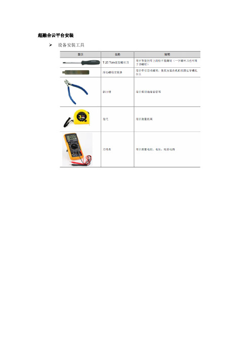
超融合云平台安装➢设备安装工具➢安装流程图➢将滑道的外导轨安装到机柜上,内导轨安装到设备上。
➢水平抬起设备,将设备沿滑道推入机柜。
➢固定设备。
将设备两侧挂耳紧贴机柜方孔条,打开智能挂耳的锁扣,用螺丝刀拧紧里面的松不脱螺钉。
➢连接电源线缆1. 操作注意事项•为避免人身伤害或设备损坏,使用配套的电源线缆。
•连接电源线缆前,确保设备和各个部件已安装完毕,接地线缆已连接。
2. 操作步骤(1) 将电源线缆一端插入设备后面板上的电源模块插口。
(2) 为防止电源线缆意外断开,固定电源线缆用扎带将电源线固定到电源模块的拉手处:a. 解开电源模块拉手上的扎带。
b. 使用扎带固定电源线。
将扎带多余部分缠绕到电源模块的拉手上。
将线缆固定到走线架➢布线注意事项所有线缆在走线时,请勿遮挡设备的进出风口,否则会影响设备散热。
确保线缆连接时无交叉现象,便于端口识别和线缆的插拔。
确保所有线缆都进行了有效标识,使用标签书写正确的名词,便于检索。
当前不需要装配的线缆,建议将其盘绕整理,绑扎在机柜的合适位置。
为避免触电、火灾或设备损坏,请不要将电话或通信设备连接到X10000 的RJ45 以太网接口。
使用走线架时,每条线缆要保持松弛,以免从机柜中拉出设备时损坏线缆。
交换机安装➢交换机安装流程图➢安装交换机到19英寸机柜安装前挂耳到交换机交换机仅支持将前挂耳安装在设备端口侧。
安装挂耳到设备时,将挂耳的长边贴近设备,挂耳的安装孔与设备侧面的螺钉孔对齐。
顺时针方向拧紧M4 螺钉(标配),从而将挂耳固定到设备。
➢安装交换机到机柜请操作者佩戴防静电腕带。
需确保防静电腕带与皮肤良好接触,并确认防静电腕带已经良好接地。
选择交换机在机柜上的安装位置,并在前方孔条上安装4 个浮动螺母(用户自备),左右各2个。
上下的两个浮动螺母间距为1U,保证左右对应的浮动螺母在一个水平面上。
检查并确认挂耳已固定在交换机两侧,安装前挂耳到交换机。
一位安装人员用手托住交换机的底部,沿机柜移动交换机,将挂耳安装孔与机柜前方孔条上的浮动螺母对齐。
云终端安装方法介绍-主机设置

云终端安装方法介绍云终端是使用专业嵌入式处理器、小型本地闪存,精简版操作系统的基于PC工业标准设计的小型专用商用PC。
云终端的主要功能基于网络,所以网络连接是十分重要的,保证网络接口畅通。
云终端主要是实现了主机资源共享。
为此在安装云终端时要做好以下两方面工作:一、保证主机正常运行,做好相关设置1、安装windows系统(过程略)2、安装驱动(声卡、网卡、打印机等)安装云终端驱动:将云终端小光盘放入光驱(这一项也可以在新建用户之后安装)—打开光盘(找到主机端多用户插件)—解压到电脑硬盘(如E盘)—打开找到Multi-user support.exe安装多用户插件—找到xp.reg 注册表项安装安装后重启计算机3、安装常用软件(如office、图像制作、杀毒软件等)略4、计算机设置(1)IP地址设置右击“网上邻居”点击“属性”,打开网络连接对话框,在右击“本地连接”打开属性对话框找到Internet协议(TCP/IP)点击属性,打开属性对话框,设置好各项后点击确定以上是电信网络的IP地址,(移动网络的地址不同)。
每一台主机的IP地址是不相同的,主要区分在IP地址的最后一组数据,设置时为了便于操作,一般都设置成整十或者整百的,将学校所有电脑主机的IP要做好记录,避免冲突。
(2)防火墙设置点击“开始”打开“控制面板”找到windows防火墙双击打开windows防火墙对话框点击(关闭不推荐)关闭防火墙——再点击“例外”选项卡勾选“远程协助、远程桌面”最后点击“确定”关闭对话框。
(3)节电模式设置打开我的电脑属性对话框右击—单击点击打开“硬件”选项卡点击打开“设备管理器”双击展开“网络适配器”,再双击打开“Marvell Yukon 88E8039”对话框单击“电源管理”打开“电源管理”选项卡去掉“允许计算机关闭这个设备以节约电源”前面方框内的对勾,点击确定按钮,关闭对话框。
(4)电源选项属性设置打开控制面板,找到“电源选项”双击打开“电源选项属性”对话框将“关闭监视器”“关闭硬盘”“系统待机”三项都设为“从不”,点击确定按钮,关闭对话框。
云终端虚拟化服务器安装指南

虚拟化服务器安装指南本文档中涉及的内容包括服务器操作系统的选择,以及部署服务器之前必须要做的操作。
一、准备工作硬件:•服务器1台或1台性能强劲的PC机(我们不推荐使用虚拟机部署我们的系统,因为虚拟机的性能不是很好会降低您的体验)软件:•桌面虚拟化部署套件•您需要使用的第三方软件•操作系统满足如下条件windows 7 旗舰版 64bit with sp1windows server 2008 R2 64bit with sp1网络环境:•网络的拓扑环境如下图所示将虚拟化服务器接入到内部网络中,确保需要访问的客户端与服务器的连通性。
当然网络结构并非像上图所示的这样,上图列举的例子只是一个简单的网络拓扑图,您的测试网络环境不一定要和上图一致,但是确保服务器与客户端之间的连接即可。
二、服务器操作系统的安装在指定的服务器上安装操作系统,安装的时候需要注意的是分区的操作,如果是单机版的服务器那么您在分区的时侯需要注意两点,存放虚拟机文件的分区和需要虚拟化的分区(存放虚拟机文件的分区一般不需要普通用户看到,在部署完后会隐藏起来,而需要虚拟化的分区则是虚拟用户对其操作后不会影响到真实机器的盘符,当然这个分区也是可以修改的)我们举一个服务器盘符规划的例子例子1:用户要求虚拟化用户可以看见C D盘符那么您就必须在系统中划分三个盘符即 C D E ,预留的E盘是当作存放虚拟机文件的盘符。
服务器的盘符如下所示,图中红色矩形框中为需要虚拟化的盘符E盘为存放虚拟机文件的盘符在安装的时候您需要这样设置(您在安装的时候务必使用administrator账户进行安装)选择中文安装界面选择语言后会弹出一些必须组件的安装界面,这些组件需要用户手动安装,安装的过程中保持默认配置即可,宗旨是务必安装成功。
在下图中有四点重要的配置•第一个红色矩形框选择的是存放虚拟机文件的盘符•第二个红色矩形框选择的是需要被虚拟化的盘符•第三个红色矩形框是确认虚拟目录的位置(即是存放虚拟机文件的位置)•第四个红色矩形框的选择视具体的操作系统而定•当您安装的是windows 7 旗舰版64bit的话那么您必须安装 Thinstuff 或 2x的terminal软件才可以使服务器支持多用户同时登录。
13-Passport5430安装配置手册-附命令行配置-V1

Passport 5430安装配置手册目录初始化配置 (3)初始化配置准备工作 (3)运行安装脚本进入交互式配置状态 (4)进入bcc配置模式 (11)用Site Manager完成其他配置 (12)Site Manager方式的配置方法简介 (13)SNMP管理功能 (13)添加和删除tcp和telnet、ftp (13)5430上定义访问控制(Traffic Filter) (14)命令行方式配置命令简介 (15)修改密码 (15)用命令行配置Traffic Filter (15)Traffic Filter 的组成 (15)创建IP Traffic Filter模板 (15)生成IP Inbound Traffic Filter (16)指定Match Criteria (16)指定Source and destination network (17)Source and destination TCP and UDP port (17)Protocol type (18)Type of service (19)Established TCP ports (19)User-defined criteria (19)指定Inbound Traffic Filters和Templates的执行动作(actions) (20)禁用和重新启用IP Traffic Filters与IP接口 (22)Traffic Filter配置举例 (22)用TFTP备份和恢复配置文件 (25)初始化配置初始化配置准备工作出厂配置需要通过console口进行。
用随机带的console线缆连接pc机的串口,通过超级终端进行配置。
超级终端设置:9600-N-1-None。
注意:如果不是出厂设置,通过$boot pp5430.exe ti_pp5430.cfg命令,设备重启进入空配置状态。
下面是终端窗口的提示信息:Nortel Networks, Inc. and its Licensors.Copyright 1992,1993,1994,1995,1996,1997,1998,1999. All rights reserved.Login: Managerpowerjs_net3Mounting new volume...Device label:Directory: 1:New Present Working Directory: 1:Welcome to the Backbone Technician Interface[1:1]$[1:1]$ dir // dir命令查看存储卡的文件和剩余空间V olume in drive 1: isDirectory of 1:File Name Size Date Day Time--------------------------------------------------------pp5430.exe 5468858 05/08/2000 Mon. 18:33:58ti_pp5430.cfg 132 05/08/2000 Mon. 18:33:58inst_pp5430.bat 147714 05/08/2000 Mon. 18:33:58debug.al 12319 05/08/2000 Mon. 18:33:58bcc_pp5430.hlp 479890 05/08/2000 Mon. 18:33:58pp5430boot.ppc 346204 05/08/2000 Mon. 18:33:58pp5430diag.a 998920 05/08/2000 Mon. 18:33:58pp5430diag.exe 564760 05/08/2000 Mon. 18:33:58pp5430ram.exe 258541 05/08/2000 Mon. 18:33:58config.0705 4628 04/29/2001 Sun. 22:46:54config 132 05/08/2000 Mon. 18:33:5833554432 bytes - Total size25271926 bytes - Available free space25007126 bytes - Contiguous free space运行安装脚本进入交互式配置状态注:根据提示输入,除telnet选项打开外,其余用默认值;site manager workstation 不要输入ip地址,跳过去。
- 1、下载文档前请自行甄别文档内容的完整性,平台不提供额外的编辑、内容补充、找答案等附加服务。
- 2、"仅部分预览"的文档,不可在线预览部分如存在完整性等问题,可反馈申请退款(可完整预览的文档不适用该条件!)。
- 3、如文档侵犯您的权益,请联系客服反馈,我们会尽快为您处理(人工客服工作时间:9:00-18:30)。
Netstation5530
安装指南
北京信达通利科技发展中心
制 作
网
线网
线
线线 网网 线V G
线
A 线
线A
G
V 线A V G V G 线A G A V 线线
路由器
主机
终端显示
终端盒
一直点击[下一步]哦
一定要选择[我同意]
这里一定要打“勾”
终端机会自动把同一个网段的安装终端服务软件的主机名列出,然后点击在屏幕上的
地址获取方式分两种,一种是自动获的;另一种是静态指定)
这里应该显示你主机的名称
如果主机上设立了多个用户名,只要填上其中一个填在用户名的位置就可以,如果没有密码
如下所示:
解决方法:
1、进入[setup] 设置程序。
选择所需要的分辨率和[Use 75HZ VSYHC]
设置一下,主机的IP地址和分辨率,保存退出即可。
