全感应车位锁DH-IPMPL-100AD产品规格说明书-蜂助手代理
车位锁的具体功能

有很多朋友现在也经常被‘停车难’,‘停车乱’的问题困扰。
也有不少人买了车位锁来想解决自己的麻烦。
但也有很多人因为不懂具体功能,对此持围观状态。
现在,以拓泰车位锁为例,来让这一部分人来了解一下车位锁。
耐压:(以防万一遭到碾压)
车位锁在下降状态可以承受500公斤的碾压而不损坏。
自锁:(安全保证除主人外其他人开不起来)
车位锁在立起和倒下状态是,除主人外其他外力不可永久地改变现状。
手动:(方便更换电池)
可以随手拉起车位锁摇臂,以便取出电池充电或进行更换。
密封:(以防雨水、灰尘等)
符合IP防护等级65,完全防止粉尘进入。
可用水冲洗且无任何伤害。
遇阻断电:(确保安全)
当车位锁在升、降过程中受到了自身不能承受的外力时会自动切断电源以保护电机不受损坏。
缺电指示:
当电池电力不足以启动车位锁是,车位锁会用发光闪烁或发出警示声来提醒用户给电池充电。
遇外力报警复位:
当车位锁在升起状态是摇臂收外力被强制压倒,在外力作用下,摇臂前、后角度发生变化,车位锁会发出报警声响外力施加者和车位锁主人来进行处理,5-10秒后摇臂会自动复位。
防盗:
车位锁与地面安装用的地脚位置在大盖子里面,而钥匙只有使用者用钥匙才能打开,实现车位锁防盗。
以上就是拓泰车位锁的大致功能,基本上用户能想到的问题它都能解决。
这才是一款合格的车位锁。
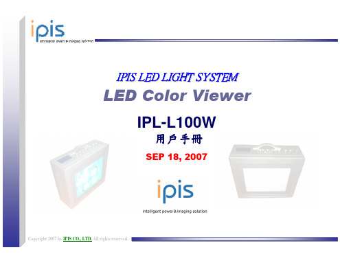
ipis IPL-L100W 说明书
產品使用方法
● 風扇操作條件設定在中心温度
−UP / DOWN 按鈕
−當你按下UP按鈕0.5秒後再按下DOWN按鈕,將可把游標移往右邊。 −當你按下DOWN按鈕0.5秒後再按下UP按鈕,將可把游標移往左邊。 −如果你同時按UP和DOWN按鈕1秒時,將顯示存取模 式。
Copyright 2007 by IPIS CO., LTD. All rights reserved.
9
產品使用方法
自動模式B Begin/End 設定
● 自動模式B: 操作設定從begin No. 到 end No.
−UP / DOWN 按鈕 −當你按下UP按鈕0.5秒後再按下DOWN按鈕,將可把游標移往右邊。 −當你按下DOWN按鈕0.5秒後再按下UP按鈕,將可把游標移往左邊。 −如果你同時按UP和DOWN按鈕1秒時,將顯示存取模式。
££Mft&1~Jfl ~111
J1AA1t
a IPL-LIOOW :£-I-k1!.18 iii ~Ji.{fJ ~LED*-~f(.1f JJt {fJ jf- if ' t.,(~~ ~.£_.&.ajJ{ it* ~ 0
~ lH1 it~#";t il-eiifit~. " {fJ ~~;ftr/F ~ {fJ ~Ji. ' IPL-LIOOW"iif t.,( ~jt§ tt~iIjt i8.~ft~{#. )JtlJ
Copyright 2007 by IPIS CO., LTD. All rights reserved.
目錄
1
重要的安全守則
使用產品前請詳讀下列指示
小心 此符號表示可能會對人體造成傷害或只對財物造成損害
车位锁使用说明

车位锁使用说明一、产品介绍车位锁是一种用于保护车辆停放位置的设备,通常由铁制材料制成,可以通过控制开关来锁定或解锁车位。
车位锁的主要功能是防止他人占用车位,确保车主可以随时停放车辆。
二、安装步骤1.准备工作在安装车位锁之前,需要确认车位的地面是否平坦,是否有足够的空间容纳车位锁。
还需准备好所需的安装工具,如螺丝刀,扳手等。
2.安装车位锁基座将车位锁基座放置在车位上,并确保与地面接触牢固。
然后使用螺丝将基座固定在地面上,以确保车位锁的稳固性。
3.安装车位锁本体将车位锁本体与基座连接,并确认连接牢固。
根据车位锁的不同类型,可能需要进行一些特殊的连接步骤,请仔细阅读产品说明书。
4.电源连接车位锁通常需要电源供应才能正常工作。
根据产品说明书,将电源线连接到车位锁的电源插座,并确保连接稳固。
三、使用方法1.开锁按下车位锁上的开锁按钮或旋转开锁开关,车位锁就会解锁。
此时,车位锁会自动抬起,车主可以将车辆停放在车位上。
2.锁定当需要锁定车位时,按下车位锁上的锁定按钮或旋转锁定开关,车位锁会自动下降并锁定在地面上,确保他人无法占用车位。
3.遥控器使用某些车位锁配备了遥控器,可以方便地控制车位锁的开锁和锁定。
使用遥控器前,请确保电池已经装入并电量充足,按下相应按钮即可操作车位锁。
四、注意事项1.检查电源在使用车位锁之前,务必检查电源是否正常连接。
如果发现电源线有损坏或者电源插座不稳固,请及时更换或修理。
2.防水防尘车位锁通常需要长时间暴露在户外环境中,为了确保其正常工作,请注意保持车位锁的防水和防尘性能,避免雨水或灰尘进入车位锁。
3.保养维护定期对车位锁进行保养维护可以延长其使用寿命。
用干布擦拭车位锁表面的灰尘和污垢,定期涂抹防锈油保护车位锁的金属部件。
4.注意安全使用车位锁时请谨慎操作,确保没有人或物品在车位锁附近。
避免在车位锁还未完全升起或降下时离开车位。
五、故障排除如果车位锁无法正常工作,可以尝试以下方法进行排除:- 确认电源连接是否稳固。
智能平板车位锁技术参数
智能平板车位锁技术参数(原创版)目录一、智能平板车位锁的简介二、智能平板车位锁的技术参数1.功能参数1) 扫码停车锁2) 地桩车库锁3) 抗压防撞4) 共享车位锁5) 充电桩控制锁2.性能参数1) 太阳能供电2) 温度适应性3) 防水防尘性能4) 抗冲击性能正文一、智能平板车位锁的简介智能平板车位锁是一种集高科技与实用性于一身的停车管理设备,旨在解决城市停车难、车位管理混乱等问题。
它具有操作简便、安全可靠、管理高效等优点,是城市停车管理的理想选择。
二、智能平板车位锁的技术参数1.功能参数(1)扫码停车锁:智能平板车位锁支持扫码停车功能,用户只需通过手机扫描车位上的二维码,即可快速完成停车缴费,实现无人值守的管理模式。
(2)地桩车库锁:地桩车库锁功能能够防止车辆在地库内乱停乱放,确保车库内的车辆摆放有序,提高车库的利用率。
(3)抗压防撞:智能平板车位锁具有较强的抗压和防撞性能,能有效保护车辆免受损害,提高车辆安全。
(4)共享车位锁:通过智能平板车位锁,用户可以实现车位共享,将空闲车位暂时出租给有需求的人,提高车位利用率,节省停车费用。
(5)充电桩控制锁:智能平板车位锁可与充电桩实现联动控制,当车辆停放在充电桩旁边时,车位锁会自动上锁,确保充电桩正常使用。
2.性能参数(1)太阳能供电:智能平板车位锁采用太阳能供电,绿色环保,无需布线,降低安装成本。
(2)温度适应性:智能平板车位锁具有较强的温度适应性,能在各种气候环境下正常工作。
(3)防水防尘性能:智能平板车位锁具有良好的防水防尘性能,能有效防止内部元件受潮、进水,保证设备正常运行。
(4)抗冲击性能:智能平板车位锁具有较强的抗冲击性能,能在遭受外力冲击时保持完好,保护车辆安全。
DH 智能交通 经济型直杆道闸 产品彩页 V1.0

关到位1路
关到位1路
关到位1路
关到位1路
防砸功能
支持,雷达防砸, 支持,雷达红外防 线圈防砸,红外防 线圈防砸,红外防 线圈防砸,红外
砸
砸
砸
防砸
供电方式
220V±10% 50/6 220V±10% 50/60 220V±10% 50/6 220V±10% 50/
外形尺寸
配套杆件
0002A-M3860 3.8米-6米可调
0002A-M3860 3.8米-6米可调
0002A-M2540 2.5米-4米可调
0002A-M2540 2.5米-4米可调
RS-485接口 1个(预留)
1个(预留)
1个(预留)
1个(预留)
I/O接口
5个(开关停各一 个输入接口,1个 常开接口,1个常 闭接口)
5个(开关停 输入接口,1 接口,1个常
各一个 个常开 闭接口
5个(开关停各一
个输入接口,1个
)常闭
开接 接口
口,1 )
个常
5个(开关停各一 个输入接口,1个 常开接口,1个常 闭接口)
网络接口 1路(RJ45调试用)1路(RJ45调试用)1路(RJ45调试用)1用路)(RJ45调试
状态输出
2路,开到位1路, 2路,开到位1路, 2路,开到位1路, 2路,开到位1路,
50.0kg
安装方式 底部安装
底部安装
底部安装
底部安装
0Hz
Hz
0Hz
60Hz
功耗
120W
120W
120W
120W
工作温度 -35℃~+65℃
-35℃~+65℃
-35℃~+65℃ -35℃~+65℃
D型智能全自动车位锁
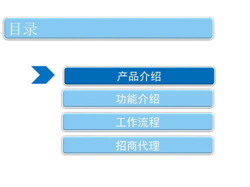
X型-自动车位锁
X型-自动车位锁
产品功能
1、超长距离红外遥控,灵敏度高,安全可靠,起降自如。使用成本低,一次充电可正常使用三个月, 整体抗压性可达2吨,使用寿命高达5年。 2、采用模具高温一次性压铸成型技术,有效提升了产品整体的强度和集成度,具有安装方便、外形 美观、结构坚固、结实耐用的特点。
3、采用行业内先进的全密闭式设计,真正实现了有效防水,可以在室内外任意场合和雨雪天气中正 常使用。
4、180度双向挡臂,具有自动复位和报警功能,车位锁挡臂在 上升和下降时,遇外力强制阻挡会报警,挡臂自动复位到原
有状态,可有效防止车位锁自身和汽车底盘的损坏。
5、具有缺电指示功能,当电池电压不足时报警器断续报警,提 醒用户及时给蓄电池充电。
6、配有故障应急装置,如遇电池耗尽或其他原因系统无法正常 工作时,可使用应急专用装置手动操作升、降车位锁挡臂。
2
停车成功
车位锁所处的环境对于车位锁的选择有很高 的要求。安装在地面上的车位锁比安装在地 下的车位锁要求要高一些。建议购买遥控车 位锁。遥控车位锁方便车主,车主不用在上 车下车打开或是关上车位锁。遥控车位锁的 防盗,防水,防撞性能也相对于比较好一点。
工作湿度 5%~95%无凝水
运行速度 4.5s
通讯速率 250kbps
传统车位保护 VS 智能车位保护
优势
成本低 无需下车开关锁
人工管理
劣势
• 人工成本高 管理不完善
• 某些场合不上档次
机械车位锁 • 需要下车开关锁 • 易损坏 • 用户体验差
遥控车位锁 • • •
易损坏 需要遥控 用户体验差
D型-智能车位保护锁
目录
产品介绍 功能介绍 工作流程 招商代理
产 品 证 明
产品证明
由深圳市保禄安防设备有限公司提供给深圳万科物业发展有限公司用于北京金域华府项目的门禁器材产品(具体产品及型号附后)均产自我公司,系完全合格之产品。
深圳市保禄安防设备有限公司定期将有关产品送相关的检测机构进行检测,不定期地在公司内部进行抽测,产品均能够达到检测机构要求的各项指标。
由我公司生产的保禄牌系列门禁器材产品均未因质量问题发生过任何纠纷。
提供给北京金域华府项目的产品如下:
深圳市保禄安防设备有限公司深圳市凯吉龙科技有限公司
二O一年月日。
智能锁使用说明书
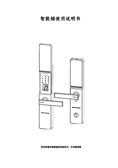
智能锁使用说明书使用前请仔细阅读使用说明书,并妥善保管第一章、概述1.简介感谢购买本公司智能锁系列产品,该系列产品采用了先进的指纹技术、非接触式刷卡、密码和钥匙作为开锁方式,并且具有多种开门模式选择,使用更灵活、更方便、更安全!开门钥匙类型用户类型数量编号范围权限指纹管理员100 0000~0099开门、管理普通用户开门密码管理员100 0000~0099开门、管理普通用户开门IC感应卡管理员100 0000~0099开门、管理普通用户开门电源供应 4.8V-6V(即4或8节干电池)典型静态电流≤90 微安(电池寿命可超过一年)工作电流<280 毫安(驱动能力强)工作温度-20℃~60℃相对湿度20% ~ 95%2.产品优势和特点开锁方式多样化:指纹、密码、刷卡、应急钥匙。
采用半导体指纹头,杜绝假指纹开锁。
有应急钥匙,电池没电或线路故障也能开锁。
应急外接电源,USB接口。
人性化设计,语音提示音量大小可调。
组合开锁,双开模式,使门锁安全更具保障。
具有防旁人窥视密码功能。
具有防撬报警功能。
具有防猫眼功能。
第二章、 产品外观图、尺寸图 1. 产品外观指纹感应卡和密把钥池盖手锁旋钮显示滑池置按键线猫眼定螺钉池定螺钉2. 尺寸图(单位mm )前面板正视图 侧视图 后面板正视图 侧视图3. 适用范围适用场所:高档住宅区、别墅、办公大楼、商务写字楼、星级酒店等。
适合门厚:40-125mm适合门类:木门、铁门及各类复合材质的防盗门。
4.开门方向室内室内左(内推)开门右(内推)开门室内室内左(外拉)开门右(外拉)开门5.更换把手方向6.键盘功说明注意:触摸面板,自动唤醒按键屏指纹锁键盘采用的是12键设计,其具体功能如下:✓ “0-9”号键:为数字键; ✓ “#”号键:进入菜单功能键; ✓ “*”号键:为清除键、返回键、退出键; ✓ “#”号键:在菜单功能状态下按“#”表示确认;注意:超过 30 秒无操作会自动退出系统,请用手背触摸按键屏唤 醒按键屏,才能继续操作(如下图)。
MPD100使用技术说明书

2
端子定义 ..................................................................................................................................8 2.1 2.2 2.3 2.4
5
操作说明 ................................................................................................................................24 5.1 5.2 5.3
6
保护功能 ................................................................................................................................29 6.1
3
安装 ........................................................................................................................................10 3....................................................................................................16 4.1 4.2 4.3 4.4 4.5 4.6 4.7 4.8 4.9 4.10 4.11 4.12 4.13 4.14
车位锁使用说明书修改版

标识卡使用说明书目录1 概述 ..................................................................1.1主要用途及特点........................................2 外形结构 ..............................................................2.1外形结构图............................................2.2外形材质..............................................2.3外形尺寸..............................................2.4产品重量..............................................3 工作原理 ..............................................................3.1工作原理..............................................4 功能特点 ..............................................................4.1自动开锁上锁..........................................4.2挡臂遇阻返回..........................................4.3扳动报警..............................................4.4缺电报警..............................................4.5车辆检测..............................................4.6一锁多卡..............................................4.7抗压与防盗............................................5 技术参数 ..............................................................5.1主要性能参数..........................................5.2使用工作条件..........................................5.3工作电压..............................................5.4工作电流..............................................5.5外壳防护等级..........................................6 安装及使用方法 ........................................................6.1安装位置..............................................6.2安装方法..............................................6.3使用方法..............................................7 故障分析与排除 ........................................................8 注意事项 ..............................................................9 产品保修说明 ..........................................................9.1三包规定..............................................9.2联系方式..............................................10 装箱单 ...............................................................1 概述1.1 主要用途及特点TZTF-8035型车位锁是一种机电一体化的智能车位锁(以下简称车位锁),常用于个人车位管理、停车场车位管理中,可以防止车位被占用。
一款蓝牙智能车位锁

一款蓝牙智能车位锁随着国民生活水平的日渐提高,汽车已日渐普及。
据中国汽车工业协会统计,2016年中国汽车产销均超2800万辆,连续八年蝉联全球第一。
然而政府或地产开发商在基础配套设施上的建设速度远远滞后于汽车产销量增长速度。
这样就带来了问题:车位有限而且很贵,花了大价钱买来的车位不时会被“鹊巢鸠占”,因此车主们很受委屈。
即便现在有了车位锁来保障车位为车主的“鹊巢鹊占”,但其操作方便程度还是有限,例如:现有车位锁的操作方式主要为两种:手动操作和红外遥控。
其中手动操作的车位锁内部只包含机械执行部分,车主必须下车后才能操作车位锁,十分不便;而红外遥控式的车位锁不让车主下车就可以智能车位锁,提高了方便程度,代价是必须让车主配备相应的专用遥控器,由于易丢失,还是存在使用上的不便。
而我司(云里物里)在现有车位锁的技术基础上,将其控制接收部分增加或改成蓝牙通信模块,大大提高了车主对车位锁控制的便捷程度。
那秘密何在?下面结合图1并通过对蓝牙智能车位锁(以下简称智能车位锁)工作原理的简单介绍来揭开这个秘密,智能车位锁主要由电气控制模块,机械执行机构和蓝牙通信模块组成,通过无线信道与手机的蓝牙通信模块传输数据,并由手机的APP对智能车位锁的工作状态进行软件操作控制,例如:当车主的车准备离开车位时,车主在手机APP上按“闭车位锁”,此时该命令以数据的方式通过手机的蓝牙通信模块调制成射频信号,并通过无线信道传输到智能车位锁端的蓝牙通信模块解调,经解调后的信号亦即数字信号,经数模转换后在电气控制模块中进行功率放大,而后驱动直流电机转动智能车位锁的挡臂轴,使得挡臂经转动90度角由水平放置状态变为竖直放置状态,防止了不受欢迎的“入侵者”。
如果车主的车将要停泊车位时,只需车主在APP上按“开车位锁”,智能车位锁挡臂就快速转为水平放置,在达到近距离的人不移离车的便捷操作效果,充分应用了手机这个常用便携电子设备,避免了携带其他设备的负担。
D40ML系列RFID磁锁产品说明书
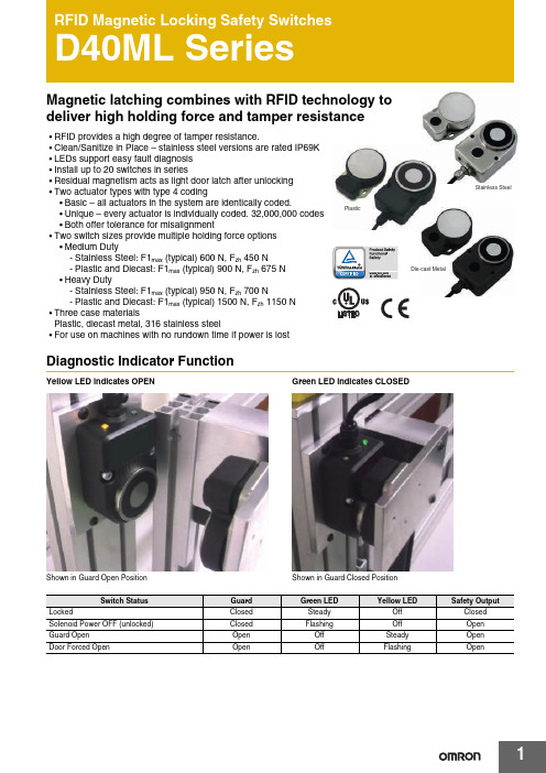
1Stainless SteelPlasticDie-cast MetalMagnetic latching combines with RFID technology to deliver high holding force and tamper resistance•RFID provide s a high degree of t a mper re s i s t a nce.•Cle a n/Sa nitize in Pl a ce – s t a inle ss s teel ver s ion s a re r a ted IP69K •LED s s upport e as y f a ult di a gno s i s •In s t a ll up to 20 s witche s in s erie s•Re s idu a l m a gneti s m a ct s as light door l a tch a fter unlocking •Two a ctu a tor type s with type 4 coding•B as ic – a ll a ctu a tor s in the s y s tem a re identic a lly coded.•Unique – every a ctu a tor i s individu a lly coded. 32,000,000 code s •Both offer toler a nce for mi sa lignment•Two s witch s ize s provide multiple holding force option s •Medium Duty-S t a inle ss S teel: F1m a x (typic a l) 600N, F zh 450N -Pl as tic a nd Diec as t: F1m a x (typic a l) 900N, F zh 675N •He a vy Duty-S t a inle ss S teel: F1m a x (typic a l) 950N, F zh 700N-Pl as tic a nd Diec as t: F1m a x (typic a l) 1500N, F zh 1150N •Three c as e m a teri a l sPl as tic, diec as t met a l, 316 s t a inle ss s teel•For u s e on m a chine s with no rundown time if power i s lo s tDiagnostic Indicator FunctionYellow LED indicates OPENS hown in Gu a rd Open Po s itionGreen LED indicates CLOSEDS hown in Gu a rd Clo s ed Po sition Switch StatusGuard Green LED Yellow LEDSafety OutputLockedClo s ed S te a dy Off Clo s ed S olenoid Power OFF (unlocked)Clo s ed Fl as hing Off Open Gu a rd Open Open Off S te a dy Open Door Forced OpenOpenOffFl as hingOpenD40ML Series2Ordering InformationSwitchesSpare ActuatorsNote:S p a re a ctu a tor s a re not a v a il a ble for uniquely coded s witche s.AccessoriesNote:1.The quick di s connect c a ble h as a n identic a l c a ble pining as the Cable Wiring on p a ge 42.Y92E-M12PUR S H8S M-L di s connect c a ble s a re a l s o comp a tible with D40ML.Case Material Holding Force F1max (typical)Actuator Type Cable Configuration Model Number316 S t a inle ssS teel (IP69K)600NUnique5m C a ble D40ML-SS2-U-5M10m C a ble D40ML-SS2-U-10MPigt a il w/ M12 Connector D40ML-SS2-U-M12B as ic5m C a ble D40ML-SS2-B-5M10m C a ble D40ML-SS2-B-10MPigt a il w/ M12 Connector D40ML-SS2-B-M12 950NUnique5m C a ble D40ML-SS1-U-5M10m C a ble D40ML-SS1-U-10MPigt a il w/ M12 Connector D40ML-SS1-U-M12B as ic5m C a ble D40ML-SS1-B-5M10m C a ble D40ML-SS1-B-10MPigt a il w/ M12 Connector D40ML-SS1-B-M12Pl as tic (IP67)900NUnique5m C a ble D40ML-P2-U-5M10m C a ble D40ML-P2-U-10MPigt a il w/ M12 Connector D40ML-P2-U-M12B as ic5m C a ble D40ML-P2-B-5M10m C a ble D40ML-P2-B-10MPigt a il w/ M12 Connector D40ML-P2-B-M12 1500NUnique5m C a ble D40ML-P1-U-5M10m C a ble D40ML-P1-U-10MPigt a il w/ M12 Connector D40ML-P1-U-M12B as ic5m C a ble D40ML-P1-B-5M10m C a ble D40ML-P1-B-10MPigt a il w/ M12 Connector D40ML-P1-B-M12Diec as t Met a l(IP67)900NUnique5m C a ble D40ML-M2-U-5M10m C a ble D40ML-M2-U-M12Pigt a il w/ M12 Connector D40ML-M2-U-M12B as ic5m C a ble D40ML-M2-B-5M10m C a ble D40ML-M2-B-10MPigt a il w/ M12 Connector D40ML-M2-B-M12 1500NUnique5m C a ble D40ML-M1-U-5M10m C a ble D40ML-M1-U-10MPigt a il w/ M12 Connector D40ML-M1-U-M12B as ic5m C a ble D40ML-M1-B-5M10m C a ble D40ML-M1-B-10MPigt a il w/ M12 Connector D40ML-M1-B-M12Product Description Model Number S t a inle ss S teel; IP69K; 950N; B as ic Code; Actu a tor D40ML-SS1-B-ACTS t a inle ss S teel; IP69K 600N; B as ic Code; Actu a tor D40ML-SS2-B-ACT Diec as t Met a l; IP67; 1500N; B as ic Code; Actu a tor D40ML-M1-B-ACTDiec as t Met a l; IP67; 900N; B as ic Code; Actu a tor D40ML-M2-B-ACTPl as tic; IP67; 1500N; B as ic Code; Actu a tor D40ML-P1-B-ACTPl as tic; IP67; 900N; B as ic Code; Actu a tor D40ML-P2-B-ACTProduct Description Model Number Quick Di s connect C a ble, 8-pin M12 to Flying Le a d s, PVC J a cket, 5 Meter Length D40ML-CBL-M12-5M Quick Di s connect C a ble, 8-pin M12 to Flying Le a d s, PVC J a cket, 10 Meter Length D40ML-CBL-M12-10MD40ML Series3SpecificationsNote:When the product u s e devi a te s from the s e ass umption s (different lo a d, oper a ting frequency, etc.) the v a lue s mu s t be a dju s ted a ccordingly.Codes and StandardsIEC 60947-5-3:2013, EN 60947-5-1:2004 + AC:2005 + A1:2009, EN 60947-1:2007 + A1:2011, EN I S O 13849-1:2008 + AC:2009, EN 62061:2005 + AC:2010 + A1:2013, I S O 14119:2013, UL508Safety Classificationand Reliability Data Minimum Switched Current 10VDC 1mA Dielectric Withstand 250VAC Insulation Resistance 100M ΩShock Resistance 11m s 30GVibration Resistance 10 to 55Hz, 1mm a mplitude Switching Distance S a o 1mm Clo s e; S a r 10mm OpenMisalignment Between s witch a nd a ctu a tor, 2mm in a ny direction Switching Frequency 1.0Hz m a ximum Response Time (On –> Off)10m s m a x.Operating Time (Off –> On)150m sApproach Speed200mm/m to 1000mm/sBody MaterialD40ML-P_: Pl as ticD40ML-M_: Diec as t Met a lD40ML-SS _: 316 S t a inle ss S teel Actu a tor S e a l: S iliconeEnc a p s ul a tion: High Temper a ture Epoxy Operating Temperature Range–25 to 40°CAmbient Operating Humidityup to 90% a t 25 ~ 40°CEnclosure Protection IP67 (Pl as tic or Diec as t Met a l)IP69K (S t a inle ss s teel ver s ion s with flying le a d s )Cable Type PVC 8 core, 6mm outer di a meter Mounting Bolts 2 × M5 Tightening torque 1.0Nm Mounting Position AnyPower Supply 24VDC ±10% (s elv / pelv)Power ConsumptionUnlocked: 50mA m a x.Locked:- Medium Duty 325mA m a x. - He a vy Duty 500mA m a x.Holding ForceMedium Duty- S t a inle ss S teel: F1m a x (typic a l) 600N, F zh *1 450N - Pl as tic a nd Diec as t: F1m a x (typic a l) 900N, F zh 675N He a vy Duty- S t a inle ss S teel: F1m a x (typic a l) 950N, F zh 700N- Pl as tic a nd Diec as t: F1m a x (typic a l) 1500N, F zh 1150N *1A new te s t h as been introduced with the coefficient 1.3. A device with a s pecified m a ximum holding force (F zh ) of 500N need s to hold up a force te s t (F1m a x ) a t 650N.According to the s t a nd a rd the locking force F zh s hould be s t a ted for every gu a rd locking s witch.Max. Switched Current (Outputs)200mA (min. intern a l re s i s t a nce 8.5 Ohm s )Auxiliary Signal+24 VDC (Door Open)Characteristic Data according to EN ISO13849-1PLe: If both ch a nnel s a re u s ed in combin a tion with a S IL3/PLe control device C a tegory: C a t. 4MTTFd: 1100aDi a gno s tic Cover a ge DC: 99% (high)Number of oper a ting d a y s per ye a r: d op = 365d Number of oper a ting hour s per d a y: h op = 24h B10d: Not mech a nic a l p a rt s implemented Characteristic Data according to IEC62061 (used as a sub system)Sa fety Integrity Level: S IL3PFH (1/h): 4.77E-10 Corre s pond s to 4.8% of S IL3PFD: 4.18E-05 Corre s pond s to 4.2% of S IL3Proof Te s t Interv a l T 1: 20aInformation with regard to UL508U s e LVLC or Cl ass 2 s upply. Type 1 enclo s ure.Risk Time in accordance with EN 60947-5-3150m s (s witching off del a y a t remov a l of a ctu a tor)D40ML Series4Cable WiringTypical Operating Distance (Front Approach)Note:DO NOT u s e s witch a nd a ctu a tor as a gu a rd door stop.Solenoid Supply 24 VDCAuxSafety Output 2Safety Output 1External Supply 24 VDCNon-Contact RFID Locking Switch Wiring DiagramQuick Connect(CC)M12 8-way maleplugConductorColorsFunction Power Rating8Or a ngeApply Lock(24VDC ±10%)50mA M a x5BrownAuxili a ry S ign a l(Door Open/Clo s ed)+24VDC(200mA)4Yellow Sa fety Output 2200mA M a x6Green Sa fety Output 21White Sa fety Output 1200mA M a x7Bl a ck Sa fety Output 13Blue0VDC500mA M a x2Red+24VDC ±10%Misalignment mmDistance mmD40ML Series5Dimensions(Unit: mm)D40ML Medium Duty SwitchD40ML Heavy Duty SwitchInstallation:•In s t a ll a tion of a ll D40ML s erie s sa fety s witche s mu s t be in a ccord a nce with a ri s k ass e ss ment for the individu a l a pplic a tion.•The u s e of a sa fety rel a y i s required for monitoring RFID coded s witche s . The s e rel a y s monitor two redund a nt circuit s as per I S O13849-1 for up to PLe/C a tegory 4 protection.•D40ML s erie s s witche s a re de s igned to oper a te with mo s t du a l ch a nnel sa fety rel a y s to sa ti s fy EN60947-5-3.•M5 mounting bolt s mu s t be u s ed to mount the s witche s . Tightening torque for mounting bolt s to en s ure reli a ble fixing i s 1.0 Nm. Alw a y s mount on non-ferrou s m a teri a l s .•Do not mount a dj a cent s witche s or a ctu a tor s clo s er th a n 30mm.•To a chieve nomin a l holding force en s ure f a ce-to-f a ce a lignment of m a gnetic p a rt s .•After in s t a ll a tion a lw a y s check e a ch s witch function by opening a nd clo s ing e a ch gu a rd individu a lly in turn a nd en s uring th a t the Green LED on the s witch a nd the LED s on the sa fety rel a y a re illumin a ted when the s witch i s clo s ed a nd a re extingui s hed when the s witch i s open. Check th a t the m a chine s top s a nd c a nnot be re-s t a rted when e a ch s witch i s open.Maintenance/Safety Checks: Monthly: Check a lignment of a ctu a tor a nd look for s ign s of mech a nic a l d a m a ge to the s witch c as ing or c a ble s .The sa fety function s a nd mech a nic s mu s t be te s ted regul a rly. For a pplic a tion s where infrequent gu a rd a cce ss i s fore s ee a ble, the s y s tem mu s t h a ve a m a nu a l function te s t to detect a po ss ible a ccumul a tion of f a ult s . At le as t once per month for PLe C a t3/4 or once per ye a r for PLd C a t3 (I S O13849-1). Where po ss ible it i s recommended th a t the control s y s tem of the m a chine dem a nd s a nd monitor s the s e te s t s , a nd s top s or prevent s the m a chine from s t a rting if the te s t i s not done. (I S O14119). Check th a t the m a chine s top s a nd c a nnot be re-s t a rted when e a ch s witch i s open.NOTE: The sa fety output s will only clo s e when the a ctu a tor i s in pl a ce a nd the lock m a gnet i s energized. Forcing open of the lock will c a u s e the sa fety output s to open.IMPORTANT: The gu a rd holding h as no interlock function. The Ri s k A ss e ss ment for the p a rticul a r a pplic a tion s hould include the ri s k of s p a re a ctu a tor s . S p a re a ctu a tor s s hould not be re a dily a v a il a ble a nd mu s t be s ecurely controlled. Record a ny RFID code s as required by f a ctory rule s or with reference to a ny ri s k ass e ss ment for the p a rticul a r a pplic a tion a nd u s er loc a tion.Fixing Holes for M5 ScrewsACTUATORSWITCHFixing Holes for M5 Screws64648896Ø 5058.5060.50411R 32437523225445232626.50SWITCH Fixing Holes for M5 ScrewsFixing Holes for M5 ScrewsACTUATOR11579.5010575.50Ø 6544116666Ø 76Ø 805252443228.504338631D40ML Series6Wiring OptionsD40ML to G9SE-201(up to Safety PLe acc. EN ISO13849-1)D40ML to G9SE-201 - Series Connections (up to SafetyPLd acc. EN ISO 13849-1, maximum 20 switches)M: 3-phase motorTerms and Conditions AgreementRead and understand this catalog.Please read and understand this catalog before purchasing the products. Please consult your OMRON representative if you have any questions or comments.Warranties.(a) Exclusive Warranty. Omron’s exclusive warranty is that the Products will be free from defects in materials and workmanshipfor a period of twelve months from the date of sale by Omron (or such other period expressed in writingby Omron). Omron disclaims all other warranties, express or implied.(b) Limitations. OMRON MAKES NO WARRANTY OR REPRESENT ATION, EXPRESS OR IMPLIED, ABOUTNON-INFRINGEMENT, MERCHANT ABILITY OR FITNESS FOR A PARTICULAR PURPOSE OF THEPRODUCTS. BUYER ACKNOWLEDGES THA T IT ALONE HAS DETERMINED THA T THE PRODUCTS WILLSUIT ABL Y MEET THE REQUIREMENTS OF THEIR INTENDED USE.Omron further disclaims all warranties and responsibility of any type for claims or expenses based on infringement by the Products or otherwise of any intellectual property right. (c) Buyer Remedy. Omron’s sole obligation hereunder shall be, at Omron’s election, to (i) replace (in the form originally shipped with Buyer responsible for labor charges for removal or replacement thereof) thenon-complying Product, (ii) repair the non-complying Product, or (iii) repay or credit Buyer an amount equal to the purchase price of the non-complying Product; provided that in no event shall Omron be responsible for warranty, repair, indemnity or any other claims or expenses regarding the Products unless Omron’s analysis confirms that the Products were properly handled, stored, installed and maintained and not subject to contamination, abuse, misuse or inappropriate modification. Return of any Products by Buyer must be approved in writing by Omron before shipment. Omron Companies shall not be liable for the suitability or unsuitability or the results from the use of Products in combination with any electrical or electronic components, circuits, system assemblies or any other materials or substances or environments. Any advice, recommendations or information given orally or in writing, are not to be construed as an amendment or addition to the above warranty.See /global/ or contact your Omron representative for published information.Limitation on Liability; Etc.OMRON COMP ANIES SHALL NOT BE LIABLE FOR SPECIAL, INDIRECT, INCIDENT AL, OR CONSEQUENTIAL DAMAGES, LOSS OF PROFITS OR PRODUCTION OR COMMERCIAL LOSS IN ANY WAY CONNECTED WITH THE PRODUCTS, WHETHER SUCH CLAIM IS BASED IN CONTRACT, WARRANTY, NEGLIGENCE OR STRICT LIABILITY.Further, in no event shall liability of Omron Companies exceed the individual price of the Product on which liability is asserted.Suitability of Use.Omron Companies shall not be responsible for conformity with any standards, codes or regulations which apply to the combination of the Product in the Buyer’s application or use of the Product. At Buyer’s request, Omron will provide applicable third party certification documents identifying ratings and limitations of use which apply to the Product. This information by itself is not sufficient for a complete determination of the suitability of the Product in combination with the end product, machine, system, or other application or use. Buyer shall be solely responsible for determining appropriateness of the particular Product with respect to Buyer’s application, product or system. Buyer shall take application responsibility in all cases.NEVER USE THE PRODUCT FOR AN APPLICA TION INVOLVING SERIOUS RISK TO LIFE OR PROPERTY OR IN LARGE QUANTITIES WITHOUT ENSURING THA T THE SYSTEM AS A WHOLE HAS BEEN DESIGNED TO ADDRESS THE RISKS, AND THA T THE OMRON PRODUCT(S) IS PROPERL Y RA TED AND INST ALLED FOR THE INTENDED USE WITHIN THE OVERALL EQUIPMENT OR SYSTEM.Programmable Products.Omron Companies shall not be responsible for the user’s programming of a programmable Product, or any consequence thereof.Performance Data.Data presented in Omron Company websites, catalogs and other materials is provided as a guide for the user in determining suitability and does not constitute a warranty. It may represent the result of Omron’s test conditions, and the user must correlate it to actual application requirements. Actual performance is subject to the Omron’s Warranty and Limitations of Liability.Change in Specifications.Product specifications and accessories may be changed at any time based on improvements and other reasons. It is our practice to change part numbers when published ratings or features are changed, or when significant construction changes are made. However, some specifications of the Product may be changed without any notice. When in doubt, special part numbers may be assigned to fix or establish key specifications for your application. Please consult with your Omron’s representative at any time to confirm actual specifications of purchased Product.Errors and Omissions.Information presented by Omron Companies has been checked and is believed to be accurate; however, no responsibility is assumed for clerical, typographical or proofreading errors or omissions.Authorized Di s tributor:In the interest of prod u ct improvement,specifications are s ub ject to change witho u t notice.Cat. No. F22E-EN-01C0421(0613)© OMRON Corporation 2013-2016 All Rights Reserved.OMRON Corporation Indu s trial Automation CompanyOMRON ELECTRONIC S LLC2895 Greenspoint Parkway, S u ite 200 Hoffman Estates, IL 60169 U.S.AT el: (1) 847-843-7900/Fax: (1) 847-843-7787Regional Headquarters OMRON EUROPE B.V.Wegalaan 67-69, 2132 JD Hoofddorp The NetherlandsTel: (31) 2356-81-300/Fax: (31) 2356-81-388 Contact: www.indu s trial.omron.euOMRON A S IA PACIFIC PTE. LTD.No. 438A Alexandra Road # 05-05/08 (Lo bb y 2), Alexandra T echnopark, Singapore 119967T el: (65) 6835-3011/Fax: (65) 6835-2711OMRON (CHINA) CO., LTD.Room 2211, Bank of China T ower, 200 Yin Cheng Zhong Road,P u Dong New Area, Shanghai, 200120, China T el: (86) 21-5037-2222/Fax: (86) 21-5037-2200。
车位锁功能说明

车位锁功能说明一语音功能语音包括语音内容、语速和音调。
语音内容包含功能要求和语音模式;语速采用中等语速,要保证发出的声音清晰、嘹亮;因语音模式的不同而采用不同的音调,譬如第一种语音模式和第三种语音模式采用庄重、大方的音调,第二种语音模式采用幽默、亲切的音调。
1 功能要求1.1 控制模块里要求提供三种语音模式供选择(客户可任选一种模式)1.2 偷盗报警(发出强烈的声响)1.3 语音出现在遥控器上2 语音模式每次语音的播出都要伴着LED灯的闪烁2.1第一种语音模式:静音要求:选择静音模式时,下面几句语音必须要有2.1.1 警报警报,电量不足,请充电2.1.2 您撞到我了,请挪开一下2.2第二种语音模式:幽默亲切2.2.1 (车辆驶进车位)您回来了,请进(检测停到位后)您辛苦了2.2.2 (车辆驶离车位)我会想您的,请您放心,我现在很好2.2.3 (电量不足)饿死了,饿死了2.2.4 (未经授权的车辆或有意无意的碰撞)哎呀,您伤到我了,好痛啊2.2.5 (车辆接近车位)嗨,我在这里2.3第三种语音模式:庄重大方2.3.1 (车辆驶进车位)车位已开,请您安全停车,(检测挺到位后)车已到位,祝您生活愉快2.3.2 (车辆驶离车位)车位已锁,祝您一路平安2.3.3 警报警报,电量不足,请充电2.3.4 (未经授权的车辆或有意无意的碰撞)您撞到我了,请挪开一下二操作功能1 车辆驶入或驶离车位1.1 车辆接近车位锁10m左右,本产品自动放下摆臂至水平位置,并伴有LED灯闪烁和语音(警报?)1.2 车辆离开车位锁10m左右,本产品自动升起摆臂至垂直位置,并伴有LED灯闪烁和语音(警报?)1.3 经授权的车辆,依靠操作密码放下摆臂后停车和语音1.4 经授权的车辆离开车位锁10m左右,车位锁自动升起摆臂至垂直位置,并伴有LED灯闪烁和语音2 显示窗口2.1 显示窗口处要安装有LED灯2.2 显示窗口屏要求触摸式2.3 在显示窗口能进行密码重置,2.4 在显示窗口屏配合下能进行遥控器的对码2.5 在显示窗口屏上可对三种语音模式进行选择3 电池对电池工作电压或电流进行检测,当工作电压或电流过低时能发出电量不足的语音4 防撞4.1 车停到位的检测4.2 垂直的摆臂感受到有外力作用下能自动摆臂到30°,当检测到外来障碍物离开后等待5~6s自动恢复到原状,同时伴有LED灯闪烁和语音摆臂在外力作用下而随外力摆臂,当外力去除后等待5~6s自动恢复到原状,同时伴有LED灯闪烁和语音。
自动识别车牌的车位锁

自动识别车牌的车位锁作者:余承阳李昊来源:《发明与创新·高中生》2022年第01期谭迪熬中国发明协会院士专家咨询工作委员会首任专家,中国发明协会中小学创造教育分会会长,科技创新教育特级教师,教育部国培计划专家库专家。
为了让自己的爱车有固定的“家”,很多人在置办房产时也会购买配套车位。
但有时候,自家车位也会被其他车辆占用,因此,人们会在车位上安装车位锁。
现有的车位锁主要有机械式和电动式两种,机械式车位锁需驾驶员下车手动升起、降下,极为不便。
电动式车位锁需通过遥控、用App控制等方式操作,虽便捷,但存在一定的安全隐患。
如何让自家车位锁能快速识别自家的车?我们对此进行了探究。
一、结构设计自动识别车牌的车位锁包括双模供电系统、车牌识别装置、车辆探测器、档杆升降装置、双色警示灯、语音提示器、远程App控制系统。
1.双模供电系统供电系统有市网、蓄電池供电两种模式。
当车位锁用于地下车库的车位时,可采用市网供电模式,无需担心断电;当车位锁用于户外车位时,可用蓄电池供电。
2.车牌识别装置车辆进入有效识别范围内,摄像头通过采集车辆图片后进行图像处理、车牌识别,并将识别结果传至主控制器。
3.车辆探测器本装置选用漫反射式红外光电传感器作为探测器。
车辆离开车位10秒后,探测器确认车辆离开,车位锁自动升起。
4.档杆升降装置档杆升降装置是车位锁的重要组成部分,由直流减速电机配合定位开关进行控制。
车位上无车辆时,档杆升起;当符合设置的车辆即将驶入车位时,档杆自动降下。
5.双色警示灯车位锁上的双色警示灯采用高亮度LED灯带设计。
当车牌与预设的相符时,绿色警示灯亮起,提醒车辆可驶入,车身全部进入车位后,绿灯熄灭。
当车牌与预设的不符时,红色警示灯以2Hz的频率快闪,提醒驾驶员不得驶入。
6.语音提示器本装置还安装了语音提示器。
车辆驶入停车位时,若车牌与预设的相符,双色警示灯绿灯亮起,档杆降到一定位置后,扬声器发出“主人,欢迎回家”的提示音。
- 1、下载文档前请自行甄别文档内容的完整性,平台不提供额外的编辑、内容补充、找答案等附加服务。
- 2、"仅部分预览"的文档,不可在线预览部分如存在完整性等问题,可反馈申请退款(可完整预览的文档不适用该条件!)。
- 3、如文档侵犯您的权益,请联系客服反馈,我们会尽快为您处理(人工客服工作时间:9:00-18:30)。
产品规格说明书
产品概述
全感应车位锁DH-IPMPL-100AD
1、增强型摇臂设计、高强化上盖设计、一体化焊接转轴、模块化结构设计、接近自动解锁下降、驶离自动上锁升起;
2、当车位锁电池电量过低时,APP连接车位锁,电量显示红色。
3、将车位锁固定于地面的螺丝孔设置在外盖内部,而外盖只能用机械钥匙开启,这样做有效降低了车位锁被盗的可能性。
4、当摇臂升降过程中受到外力阻挡时,摇臂会启动报警并反向转动恢复到初始状态;车位锁内置蜂鸣器,遇阻时蜂鸣器将持续发出声音进行报警;
5、车辆驶近车位时,距离车位锁5~10米左右,车位锁感应器自动控制车位锁下降,实现自动解锁。
6、车辆驶离车位后,通过地磁和超声波检测上方车辆离开,车位锁在10秒左右自动升起上锁。
产品参数
待机时间:12个月(基于4节1号碱性干电池)
待机功耗:≤0.8mA
联网方式:支付移动、电信NB卡
蓝牙连接:支持
蓝牙连接距离:户外>30m
433连接距离:户外>40m
车位锁感应器控制:车位锁感应器驶近控制距离:5~10米
防水等级:IPX8可防雨水浸泡
有效承重力:4吨汽车抗压
干电池:4节1号碱性干电池
防撞功能:支持180防撞
工作电压:DC5V~7V
使用环境温度:干电池:-10°C~+55°C。
