induction, resistivity and mwd tools in horizontal wells
石油工程测井基本名词解释

一、名词概念1.Well logging测井:油气田地球物理测井,简称测井welllogging,是应用物理方法研究油气田钻井地质剖面和井的技术状况,寻找油气层并监测油气层开发的一门应用技术。
2.Electrical logs电法测井:是指以研究岩石及其孔隙流体的导电性、电化学性质及介电性为基础的一大类测井方法,包括以测量岩层电化学特性、导电特性和介电特性为基础的三小类测井方法。
3.Acoustic logs声波测井:是通过研究声波在井下岩层和介质中的传播特性,来了解岩层的地质特性和井的技术状况的一类测井方法。
4.Nuclear logs核测井:是根据岩石及其孔隙流体的核物理性质,研究钻井地质剖面,勘探石油、天然气、煤以及铀等有用矿藏的地球物理方法,是地球物理测井的重要组成部分。
5.Production logs生产测井PL:泛指油气田投产后,在生产井或注入井中进行的一系列井下地球物理观测。
它是监测油气田开发动态的主要技术手段,是油气田储集层评价、开发方案编制和调整、井下技术状况检测、作业措施实施和效果评价的重要手段。
根据测量对象和应用范围,生产测井大致可分为生产动态、产层评价和工程技术三类。
6.Apparent resisitivity视电阻率:把电极系放在井中某一位置,能测得该点的一个电阻率值,该值受井眼、围岩、泥浆侵入等环境影响,不等于地层的真实电阻率,称为视电阻率。
当电极系沿井身连续移动时,则可测得视电阻率随井身变化的曲线。
这种横坐标为视电阻率Ra,纵坐标为深度H的曲线叫视电阻率曲线。
7.Reservoir储集层:在石油工业中,储集层是指具有一定孔隙性和渗透性的岩层。
例如油气水层。
8.increased resistance invasion高侵:当地层孔隙中原来含有的流体电阻率较低时,电阻率较高的钻井液滤液侵入后,侵入带岩石电阻率升高,这种钻井液滤液侵入称为钻井液高侵,RXO<Rt多出现在水层。
导电性参数_Al
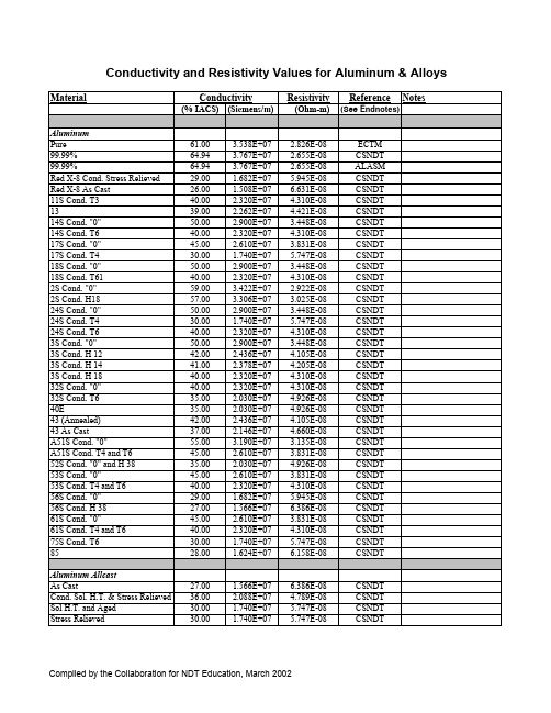
MaterialResistivityReferenceNotes(% IACS) (S ie mens /m ) (Ohm-m) (See Endnotes )AluminumPure 61.00 3.538E+07 2.826E-08ECTM 99.99%64.94 3.767E+07 2.655E-08CSNDT 99.99%64.94 3.767E+07 2.655E-08ALASM Red X-8 Cond. Stress Relieved 29.00 1.682E+07 5.945E-08CSNDT Red X-8 As Cast 26.00 1.508E+07 6.631E-08CSNDT 11S Cond. T340.00 2.320E+07 4.310E-08CSNDT 1339.00 2.262E+07 4.421E-08CSNDT 14S Cond. "0"50.00 2.900E+07 3.448E-08CSNDT 14S Cond. T640.00 2.320E+07 4.310E-08CSNDT 17S Cond. "0"45.00 2.610E+07 3.831E-08CSNDT 17S Cond. T430.00 1.740E+07 5.747E-08CSNDT 18S Cond. "0"50.00 2.900E+07 3.448E-08CSNDT 18S Cond. T6140.00 2.320E+07 4.310E-08CSNDT 2S Cond. "0"59.00 3.422E+07 2.922E-08CSNDT 2S Cond. H1857.00 3.306E+07 3.025E-08CSNDT 24S Cond. "0"50.00 2.900E+07 3.448E-08CSNDT 24S Cond. T430.00 1.740E+07 5.747E-08CSNDT 24S Cond. T640.00 2.320E+07 4.310E-08CSNDT 3S Cond. "0"50.00 2.900E+07 3.448E-08CSNDT 3S Cond. H 1242.00 2.436E+07 4.105E-08CSNDT 3S Cond. H 1441.00 2.378E+07 4.205E-08CSNDT 3S Cond. H 1840.00 2.320E+07 4.310E-08CSNDT 32S Cond. "0"40.00 2.320E+07 4.310E-08CSNDT 32S Cond. T635.00 2.030E+07 4.926E-08CSNDT 40E35.00 2.030E+07 4.926E-08CSNDT 43 (Annealed)42.00 2.436E+07 4.105E-08CSNDT 43 As Cast37.00 2.146E+07 4.660E-08CSNDT A51S Cond. "0"55.00 3.190E+07 3.135E-08CSNDT A51S Cond. T4 and T645.00 2.610E+07 3.831E-08CSNDT 52S Cond. "0" and H 3835.00 2.030E+07 4.926E-08CSNDT 53S Cond. "0"45.00 2.610E+07 3.831E-08CSNDT 53S Cond. T4 and T640.00 2.320E+07 4.310E-08CSNDT 56S Cond. "0"29.00 1.682E+07 5.945E-08CSNDT 56S Cond. H 3827.00 1.566E+07 6.386E-08CSNDT 61S Cond. "0"45.00 2.610E+07 3.831E-08CSNDT 61S Cond. T4 and T640.00 2.320E+07 4.310E-08CSNDT 75S Cond. T630.00 1.740E+07 5.747E-08CSNDT 8528.00 1.624E+07 6.158E-08CSNDTAluminum Allcast As Cast27.00 1.566E+07 6.386E-08CSNDT Cond. Sol. H.T. & Stress Relieved 36.00 2.088E+07 4.789E-08CSNDT Sol H.T. and Aged 30.00 1.740E+07 5.747E-08CSNDT Stress Relieved30.00 1.740E+07 5.747E-08CSNDTConductivityConductivity and Resistivity Values for Aluminum & AlloysAluminum Alloy (Wrought)1050-061.30 2.810E-08ALASM 1060-O62.00 2.780E-08ALASM 1060-H1861.00 2.780E-08ALASM 110057.00 - 61.80 3.445E+07 2.903E-08NDT Mag 1100-O59.00 2.920E-08ALASM 1100-H1857.00 3.020E-08ALASM 1145-O61.00 2.830E-08ALASM 1145-H1860.00 2.830E-08ALASM 1199-O64.50 2.670E-08ALASM 1350-O61.80 2.790E-08ALASM 1350-H x61.00 2.820E-08ALASM 2011-T336.00 - 36.50 2.103E+07 4.756E-08NDT Mag 2011-T3 and T439.00 4.400E-08ALASM 2011-T845.00 3.800E-08ALASM 2014-F and -048.60 - 50.70 2.880E+07 3.473E-08NDT Mag 2014-O50.00 3.400E-08ALASM 2014-T3 and -T432.50 - 34.80 1.952E+07 5.124E-08NDT Mag 2014-T3, T4, and T45134.00 5.100E-08ALASM 2014-T638.00 - 39.70 2.253E+07 4.438E-08NDT Mag 2014-T6, T651, and T65240.00 4.300E-08ALASM 2017-F49.30 - 49.50 2.865E+07 3.490E-08NDT Mag 2017-O50.00 3.500E-08ALASM 2017-T434.00 5.000E-08ALASM 2024-F46.80 - 48.50 2.764E+07 3.618E-08NDT Mag 2024-O50.00 3.400E-08ALASM 2024-T328.60 - 36.10 1.876E+07 5.330E-08NDT Mag 2024-T3629.10 - 29.50 1.699E+07 5.884E-08NDT Mag 2024-T3, T36, T351, T361, and T430.00 5.700E-08ALASM 2024-T428.80 - 31.00 1.734E+07 5.766E-08NDT Mag 2024-T6, T81, T851, and T86138.00 4.500E-08ALASM 2036-O52.00 3.320E-08ALASM 2036-T441.00 4.210E-08ALASM 2048-T85142.00 4.000E-08ALASM 2124-O50.00 3.450E-08ALASM2124-T85139.00 4.421E-08ALASM resistivity converted from conductivity--2127-T442.10 - 42.40 2.451E+07 4.081E-08NDT Mag 2218-T6137.40 2.169E+07 4.610E-08NDT Mag 2218-T6138.00 4.500E-08ALASM 2218-T7240.00 4.300E-08ALASM 2219-O44.00 3.900E-08ALASM 2219-T31, T37, and T35128.00 6.200E-08ALASM 2219-T62, T81, T87, and T85130.00 5.700E-08ALASM 2319-O44.00 3.900E-08ALASM 261840.20 2.332E+07 4.289E-08NDT Mag 2618-T6137.00 4.700E-08ALASM3003-O44.70 - 49.80 2.741E+07 3.649E-08NDT Mag 3003-O50.00 3.400E-08ALASM 3003-H14 and -H1237.80 - 51.50 2.590E+07 3.861E-08NDT Mag 3003-H1242.00 4.100E-08ALASM 3003-H1441.00 4.200E-08ALASM 3003-H1840.00 4.300E-08ALASM 3003-H24 and -H2837.80 - 47.50 2.474E+07 4.043E-08NDT Mag 300439.40 - 43.50 2.404E+07 4.160E-08NDT Mag 3004-O42.00 4.100E-08ALASM X3005-O50.10 - 50.30 2.912E+07 3.435E-08NDT Mag 3105-O45.00 3.830E-08ALASM 4032-O40.00 4.310E-08ALASM 4032-T635.30 - 36.30 2.076E+07 4.816E-08NDT Mag 4032-T636.00 4.790E-08ALASM 4043-F52.30 - 54.30 3.091E+07 3.235E-08NDT Mag 4043-O42.00 4.100E-08ALASM 500552.30 - 52.80 3.048E+07 3.281E-08NDT Mag 5005-O and H3852.00 3.320E-08ALASM 505048.30 - 49.80 2.845E+07 3.515E-08NDT Mag 5050-O and H3850.00 3.400E-08ALASM 505233.60 - 37.60 2.065E+07 4.843E-08NDT Mag 5052-O and H3835.00 4.930E-08ALASM 505628.10 - 29.80 1.679E+07 5.956E-08NDT Mag 5056-O29.00 5.900E-08ALASM 5056-H3827.00 6.400E-08ALASM 508329.00 5.950E-08ALASM 508631.00 5.600E-08ALASM 515430.50 - 32.80 1.836E+07 5.448E-08NDT Mag 515432.00 5.390E-08ALASM 518231.00 5.560E-08ALASM 525235.00 4.900E-08ALASM 525432.00 5.400E-08ALASM 5356-O29.00 5.940E-08ALASM 535742.30 - 47.00 2.590E+07 3.861E-08NDT Mag 545434.00 5.100E-08ALASM 545629.00 5.950E-08ALASM 545746.00 3.750E-08ALASM 565235.00 4.900E-08ALASM 565754.00 3.200E-08ALASM 6005-T549.00 3.500E-08ALASM 6009-O54.00 3.190E-08ALASM 6009-T444.00 3.920E-08ALASM 6009-T647.00 3.670E-08ALASM 6010-O53.00 3.250E-08ALASM 6010-T439.00 4.420E-08ALASM 6010-T644.00 3.920E-08ALASM 605339.30 - 48.00 2.532E+07 3.950E-08NDT Mag6061-F and -042.30 - 48.50 2.633E+07 3.798E-08NDT Mag 6061-O47.00 3.700E-08ALASM 6061-T437.60 - 40.50 2.265E+07 4.415E-08NDT Mag 6061-T440.00 4.300E-08ALASM 6061-T6 and -T940.00 - 44.80 2.459E+07 4.066E-08NDT Mag 6061-T643.00 4.000E-08ALASM 6062-F47.00 - 51.00 2.842E+07 3.519E-08NDT Mag 6062-T443.50 - 44.00 2.538E+07 3.941E-08NDT Mag 6062-T644.70 - 49.50 2.732E+07 3.661E-08NDT Mag 6063-O58.00 3.000E-08ALASM 6063-T150.00 3.500E-08ALASM 6063-T555.00 3.200E-08ALASM 6063-T6 and T8353.00 3.300E-08ALASM 6066-O40.00 4.300E-08ALASM 6066-T637.00 4.700E-08ALASM 6070-T644.00 3.900E-08ALASM 6101-T657.00 3.020E-08ALASM 6101-T6159.00 2.920E-08ALASM 6101-T6358.00 2.970E-08ALASM 6101-T6460.00 2.870E-08ALASM 6101-T6558.00 2.970E-08ALASM 6151-053.30 - 55.00 3.141E+07 3.184E-08NDT Mag 6151-O54.00 3.200E-08ALASM 6151-T441.50 - 43.30 2.459E+07 4.066E-08NDT Mag 6151-T642.00 4.100E-08ALASM 6151-T643.90 - 45.00 2.578E+07 3.879E-08NDT Mag 6151-T645.00 3.800E-08ALASM 6201-T8154.00 3.200E-08ALASM 6205-T145.00 3.700E-08ALASM 6205-T549.00 3.500E-08ALASM 6262-T944.00 3.900E-08ALASM 6351-T646.00 3.800E-08ALASM 6463-T150.00 3.400E-08ALASM 6463-T555.00 3.100E-08ALASM 6463-T653.00 3.300E-08ALASM 6951-F53.00 - 53.10 3.077E+07 3.250E-08NDT Mag 6951-055.70 - 56.50 3.254E+07 3.073E-08NDT Mag 7005-O43.00 4.010E-08ALASM 7005-T53, T5351, T63, and T635138.00 4.540E-08ALASM 7005-T635.00 4.930E-08ALASM703932-40 4.3E-8--5.4E-8ALASM resistivity converted from conductivity--704940.00 4.300E-08ALASM 7050-O47.00 3.670E-08ALASM 7050-T76 and T765139.50 4.360E-08ALASM 7050-T736 and T7365140.50 4.260E-08ALASM 707260.00 - 60.10 3.483E+07 2.871E-08NDT Mag 7072-O60.00 2.870E-08ALASM7075-F44.50 - 47.80 2.677E+07 3.736E-08NDT Mag 7075-T631.40 - 34.80 1.920E+07 5.209E-08NDT Mag 7075-T632.00 1.856E+07 5.388E-08ECTM 7075-W27.00 - 37.00 1.856E+07 5.388E-08NDT Mag 7075-T6, T62, T651, and T65233.00 5.220E-08ALASM 7075-T76 and T765138.50 4.480E-08ALASM 7075-T73, T7351, and T735240.00 4.310E-08ALASM 707635.00 3.750E-08ALASM 7175-O46.00 3.750E-08ALASM 7175-T6636.00 4.790E-08ALASM 7175-T736 and T7365240.00 4.310E-08ALASM 7178-O46.00 3.750E-08ALASM 7178-T6 and T65132.00 5.390E-08ALASM 7178-T76 and T765139.00 4.420E-08ALASM X7178-F and -045.50 - 46.00 2.654E+07 3.769E-08NDT Mag X7178-W and T626.80 - 32.60 1.723E+07 5.805E-08NDT Mag 7475-O46.00 3.750E-08ALASM 7475-T61 and T65136.00 4.790E-08ALASM 7475-T761 and T765140.00 4.310E-08ALASM 7475-T735142.00 4.110E-08ALASM Aluminum Alloys (Cast)122 Perm. Mold As Cast34.00 1.972E+07 5.071E-08CSNDT 122 Sand Cond. T241.00 2.378E+07 4.205E-08CSNDT 122 Sand Cond. T6133.00 1.914E+07 5.225E-08CSNDT 11330.00 1.740E+07 5.747E-08CSNDT C11327.00 1.566E+07 6.386E-08CSNDT A 132 Cond. T55129.00 1.682E+07 5.945E-08CSNDT 201.0-T627-32 4.5E-8--6.4E-8ALASM206.0-T627-32 5.4E-8--6.4E-8ALASM conductivity converted from resistivity--206.0-T732-34 5.0E-8--5.4E-8ALASM conductivity converted from resistivity--208.0 as-cast31.00 5.560E-08ALASM (208.0) 10831.00 1.798E+07 5.562E-08CSNDT 208.0 annealed38.00 4.540E-08ALASM 21435.00 2.030E+07 4.926E-08CSNDT A21433.00 1.914E+07 5.225E-08CSNDT 21824.00 1.392E+077.184E-08CSNDT 22021.00 1.218E+078.210E-08CSNDT 242.0-T21, sand44.00 3.920E-08ALASM (242.0) 142 Sand Cond. T2144.00 2.552E+07 3.918E-08CSNDT 242.0-T571, sand34.00 5.070E-08ALASM (242.0) 142 Sand Cond. T57134.00 1.972E+07 5.071E-08CSNDT 242.0-T77, sand38.00 4.540E-08ALASM (242.0) 142 Sand Cond. T7737.00 2.146E+07 4.660E-08CSNDT 242.0-T61, permanent mold33.00 5.220E-08ALASM 295.0-T435.00 4.930E-08ALASM (295.0) 195 Cond. T435.00 2.030E+07 4.926E-08CSNDT 295.0-T6237.00 4.930E-08ALASM (295.0) 195 Cond. T6237.00 2.146E+07 4.660E-08CSNDT296.0-T4 and T633.00 5.220E-08ALASM (296.0) B 195 Cond. T435.00 2.030E+07 4.926E-08CSNDT (296.0) B 195 Cond. T636.00 2.088E+07 4.789E-08CSNDT 308.037.00 4.660E-08ALASM (308.0) A 10837.00 2.146E+07 4.660E-08CSNDT R 31730.00 1.740E+07 5.747E-08CSNDT 319.027.00 6.390E-08ALASM 319 Sand27.00 1.566E+07 6.386E-08CSNDT 319 Perm. Mold28.00 1.624E+07 6.158E-08CSNDT 336.0-T55129.00 5.950E-08ALASM 355.0-T51, sand43.00 4.010E-08ALASM 355 Sand Cond. T5143.00 2.494E+07 4.010E-08CSNDT 355.0-T6, sand36.00 4.790E-08ALASM 355 Sand Cond. T636.00 2.088E+07 4.789E-08CSNDT 355.0-T61, sand39.00 4.420E-08ALASM 355 Sand Cond. T6137.00 2.146E+07 4.660E-08CSNDT 355.0-T7, sand42.00 4.100E-08ALASM 355 Sand Cond. T742.00 2.436E+07 4.105E-08CSNDT 355.0-T6, permanent mold39.00 4.420E-08ALASM 355 Perm. Mold Cond. T639.00 2.262E+07 4.421E-08CSNDT 356.0-T51, sand43.00 4.010E-08ALASM 356 Sand Cond. T5143.00 2.494E+07 4.010E-08CSNDT 356.0-T6, sand39.00 4.420E-08ALASM 356 Sand Cond. T639.00 2.262E+07 4.421E-08CSNDT 356.0-T7, sand40.00 4.310E-08ALASM 356.0-T6, permanent mold41.00 4.210E-08ALASM 360.028.00 6.160E-08ALASMA360.030.00 5.747E-08ALASM resistivity converted from conductivity--36037.00 2.146E+07 4.660E-08CSNDT 380.027.00 6.500E-08ALASM 38027.00 1.566E+07 6.386E-08CSNDT383.023.007.496E-08ALASM resistivity converted from conductivity--384.022.007.837E-08ALASM resistivity converted from conductivity--A384.023.007.496E-08ALASM resistivity converted from conductivity--390.0-F27.00 6.386E-08ALASM resistivity converted from conductivity--390.0-T525.00 6.896E-08ALASM resistivity converted from conductivity--413.031.00 5.56E-08ALASM 443.0 As-Cast37.00 4.660E-08ALASM443.0 Annealed42.05 4.100E-08ALASM conductivity converted from resistivity--514.035.00 4.930E-08ALASM518.025.00 6.896E-08ALASM resistivity converted from conductivity--520.0-T421.008.210E-08ALASM 535.020.007.500E-08ALASM 712.035.00 4.930E-08ALASM713.035.00 4.926E-08ALASM resistivity converted from conductivity--75045.00 2.610E+07 3.831E-08CSNDT771.027.00 6.386E-08ALASM resistivity converted from conductivity--850.047.00 3.670E-08ALASMALASM=ASM Specialty Handbook Aluminum and Aluminum AlloysCSNDT=CSNDT compiled by Eddy Current Technology IncorporatedECTM=Eddy Current Testing Manual on Eddy Current Method compiled by Eddy Current Technology Incorporated NDT Mag=NDT Magazine Sept/Oct 1955, Cosgrove Article compiled by Eddy Current Technology Incorporated。
Tettex 2293 风线电阻计说明书

2293Winding resistance meter with one-time-connection systemThe Tettex 2293 is the result of extensive research and years of experience testing transformers. It incorporates a fast and highly advanced procedure to measure winding resistance. A simple one-time-connection system together with the simultaneous windingmagnetization method drastically reduces measuring time.The simultaneous winding magnetization (SWM) method guarantees fast and reliable measurements even on large power transformers with delta windings on the low voltage side, where stable measurements can be seldom reached using traditional winding resistance measurement instruments.In addition, the new demagnetization functioneliminates the magnetic remanence in the core after the application of a DC voltage. This feature can be used before performing other tests such as frequency response analysis (FRA), transformer turns ratiomeasurement (TTR) or recovery voltage measurement (RVM) which are adversely affected by remanence effects.The transformer is discharged by a state-of-the-artdischarge circuit in a fraction of the time taken by other instruments. The discharging function and the“Caution” indicator continue to operate even when linepower is lost.FEATURES AND BENEFITSResistance measurement made easy – simple one-time-connection system: Once connected will test all phases and windingsLarge 7” touch screen interface with full graphical testvisualizationUnique simultaneous winding magnetization method(SWM), equivalent to traditional equipment with up to 100 A test currentTap changer control signalHeat run function and 6 temperature measurementchannels with automatic resistance value correctionData transfer over USB memory-stick or direct to PCAPPLICATIONSResistance measurement and demagnetization function for all types of highly inductive test objects.Power transformers Distribution transformers Generators and motors Instrument transformersThe 2293 is a valuable tool for factory test, acceptance test and regular maintenance.A test solution optimized for easy and fastwinding resistance measurement on power and distribution transformers as well as motors and generators.1981COMPLETE AUTOMATIC TEST PROCEDUREThe 2293 performs resistance measurements on all windings without any reconnection. The test procedure is simple and efficient. One end of the measurement cable set is connected to each bushing of the transformer using the special Kelvin clamp, while the other end is connected to the 2293.Once the cable set is connected to the test object, the instrument will automatically measure selected resistances of both windings and all phases. In addition, the motorized tap changer can be controlled to perform fully automated measurements on all taps. A complete transformer can be tested by a single person in a fraction of the time compared to traditional instruments.GRAPHICAL INTERFACEThe 7” touch screen full graphical interface guides the operator through the test procedure.Select the test object by touching the appropriate icon and press start – The unit then visualizes each test cycle and displays the results graphically or in list format. DEMAGNETIZATION FUNCTIONApplying a DC current to an inductive test object, like a power transformer, magnetizes the core. The resulting magnetic remanence will have an adverse effect on other measurements.The 2293 includes a fully automatic demagnetization feature which eliminates the magnetic remanence. Select the test object by touching the appropriate icon and press start – The unit visualizes the whole demagnetization cycleand performs the correct core demagnetization.HEAT RUN TESTThe 2293, which can measure HV and LV side resistancessimultaneously and accurately, is the perfect tool forresistance measurements during a heat run test.The instrument provides efficient and accurate acquisitionof the required data points to allow drawingthe necessary cooling curve.Results are available as CSV and can be easily exported.DATA HANDLING AND TEST REPORTSThe 2293 allows easy data handling. Results can be savedon a USB memory stick or transferred to any computer. Inaddition the instrument can be connected via Ethernet to aLAN. It also includes a thermal printer for immediate reportprinting.SelectStartResults can also be saved in the instrument’s memorywhile continuing testing, to be downloaded later afterhaving returned to the office.ResultsTECHNICAL SPECIFICATIONSResistance MeasurementMax. Measuring Current 32 A (user selectable) Max. Charging Voltage 100 VRange 0.1 μΩ … 300 k ΩResistance Accuracy(1) 0.1 μΩ ... 300 μΩ 0.1% ± 0.5 μΩ300.1 μΩ … 30 k Ω 0.1% 30.01 k Ω … 300 k Ω 1% Mains Power Supply Voltage90 VAC … 264 VAC Maximum Power 1 kWFrequency 47 Hz … 63 HzEnvironmentalOperating temperature -10°C … +60°C Storage temperature -20°C ... +70°CHumidity 5% … 90% r.h. non-condensing MechanicalDimensions (W x D x H) 521 mm x 425 mm x 216 mmWeight (2)17.8 kg (2) Measuring cables not included (1) at temperature 0 … 50°C at highest available current Functions- 8 measuring channels (2 x 3 phases and 2 x 1 neutral)- 6 temperature channels with automatic resistance correction - Advanced 7” graphical touch screen interface- High efficient DC supply with SWM (simultaneous winding magnetization)- SWM mode and Classic mode (for traditional resistance measurement method) - Turbo discharge circuit- Automated demagnetizing function with flux indicator - Automatic heat run function- Tap changer control signal to automate test procedures on transformers with motorized tap changer - Internal memory >10'000 measurements- USB and LAN connections. Data can be saved on a memory stick or directly transferred to PC - Charges any inductive load and works with any resistive or inductive test object - Heavy duty protection circuit- Safety circuit ensures discharge even when line power is lost - Caution indicator - Built-in printerSCOPE OF SUPPLYMeasuring unit, cable set (10 m), carrying bag, test certificate, user manualOptions2293/TEMP1 Temperature probe for liquids2293/TEMP2 Magnetic temperature probe for metallic test objects 2293/TAP Tap changer connection cable2293/10 10 m extension cablesTettex Instruments offers a complete portfolio for transformer testingTTR 2795 / TTR 2796Transformer Turns Ratio Meterwith 100/250 V test voltageDetection of winding movements and mechanical failures of transformers. Active probing assures reliable and repetitive measurement results. Advanced analysis and touch screen operation.FRA 5310Frequency Response AnalyserOnsite testing of turns and voltage ratio, phase displacement and excitation current. Automatic winding connection identification and vector group detection. Remotely controllable via USB.RVM 5462Recovery Voltage MeterMobile system for non-destructive diagnosis of the state of paper-oil insulation (effect of moisture content and aging) using the recovery voltagemethod.MIDAS 2880Mobile Insulation Diagnosis & Analysing SystemThe ideal tool for periodic maintenance and inspection of high voltage insulation losses, dissipation factor (tan δ), power factor and capacitance of power transformers, bushings, motors, generators etc.OC60EOil Cell TesterFully automated digital liquid electrical test set designed to reliably and accurately test the dielectric strength of insulation liquids.Europe, Asia, South & Central America, Australia Haefely Test AGLehenmattstrasse 353 4052 Basel Switzerland+ 41 61 373 4111 + 41 61 373 4912 |**************** ChinaHaefely Test AG – Beijing Office8-1-602, Fortune StreetNo. 67, Chaoyang Road, Chaoyang DistrictBeijing, 100025 P. R. China+ 86 10 8578 8099 + 86 10 8578 9908 |*****************.cnNorth America Hipotronics Inc. 1650 Route 22 PO Box 414Brewster, NY 10509USA+ 1 845 279 3644 + 1 845 279 2467|*********************。
威德福概述

定向钻井服务,
如MWD、LWD、旋转导向等, 提 高钻井效率并优化井的轨迹
控制压力钻井® (CPD®) 服务
包括欠平衡、控压钻井和空气钻 井,拥有全球最大的控制压力钻 井服务队伍。
套管钻井 (DwC™) 系统
提高钻井效率,无需起下钻,从 而减少作业风险。
专利和非专利的钻井工具
客户无需支付庞大的购买费用, 通过租赁即可享用全面的产品。
– 旋转控制装置 – 井下套管阀 • 数据采集 • 流体 • 地面系统
© 2007 Weatherford. All rights reserved.
18
钻井设备及服务
• 钻井液系统 • 地面设备 • 井下工具 • Williams 旋转
控制头
© 2007 Weatherford. All rights reserved.
24
市场
Artificial lift Casing & Tubing Services Casing Hardware & Cementation Products Completion Equipment & Services
Directional Drilling Services
Downhole Drilling Tools
ConocoPhillips
BP
油气服务公司
Total
注册的美国专利
0
9 11 13 22 30
200
400
600
800
1000
1200
Technology Strength
Source : Wall Street Journal, 6 March 2007
WFT portfolio key differentiators:
随钻电阻率测井仪器的实现

随钻电阻率测井仪器的实现黄忠富 黄瑞光(武汉华中科技大学) 陈 鹏(江汉测井研究所)摘要黄忠富,黄瑞光,陈鹏.随钻电阻率测井仪器的实现.测井技术,2002,26(2):172~175介绍最新研制的随钻电阻率测井仪器的测量原理、实现方法,并具体分析电路硬、软件的设计以及元器件选择中应注意的问题。
多次模拟运行试验表明,该仪器达到了设计指标,性能良好,稳定可靠。
关键词: 随钻测井 电缆测井 电阻率 测井仪器 原理 设计ABSTRACTH u ang Zhongfu ,H u ang R uigu ang ,Chen Peng.Development of MW D R esistivity Logging T ool.W LT,2002,26(2):172-175A new MW D resistivity logging tool has been developed.Its measurement principle ,im plementation ,hardware and s oftware designs are introduced.Problems to be n oticed in circuit design and com ponents selection are als o indi 2cated.Simulating tests sh ow this toolis up to the design standards ,better in performance and m ore reliable in quali 2ty.Subjects :MW D cable logging resistivity logging instrument principle design引言随钻测井(Measurement While Drilling )是一种比较新的技术,和传统的电缆测井相比较,随钻测井具有实时性好、测井精度高、节省测井成本等优点[1],并且当一些井不能用电缆测井,或者在某些特殊地层条件下操作困难、花费钻井时间过多的时候,就必须用随钻测井代替电缆测井。
测井(专业英语)习题

Many modern oil and gas wells are drilled directionally. At first, loggers had to run their tools somehow attached to the drill pipe if the well was not vertical.
• spontaneous potential (SP) 自然电位
• permeable beds
渗透性地层
logging procedure
测井过程
potential depth zones 有潜力井段
wireline logs 电缆测井
pressure pulses 压力脉冲
in real time
These raw measurements can then be interpreted to give a continuous measurement -versus-depth record of formation properties such as porosity, water saturation, and rock type.
different tools to measure the same basic property.
虽然测井曲线最重要的用途是进行地层对比和定位油气层,但还 可用于探测或测量地下许多需探测的重要参数。当然,针对不同 的井型和地层条件,需要采用不同的仪器来探测地层中的同一基 本特征。
在20世纪80年代和90年代之间,测井技术 进入数控时代,在此期间,测井操作变得 越来越安全可靠。
对称四极电测深法在测量场地浅部地层土壤电阻率中的应用
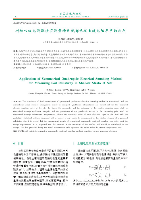
2020年第38卷第3期对称四极电测深法在测量场地浅部地层土壤电阻率中的应用王雅君,通瑞生,薛维俊(内蒙古电力勘测设计院有限责任公司,呼和浩特010011)0引言接地系统是变电站安全运行的基本保证,电气设备接地分为工作接地、保护接地与建筑物的防雷使用接地。
场地土壤电阻率是接地电阻的主要影响因素,测量场地土壤电阻率,对接地装置的正确设计起着重要作用,测量方法可选择直流电法或电磁波法[1-2]。
对于电力工程场地土壤电阻率的测试深度,中外标准均未作具体要求[3]。
目前国内外测量土壤电阻率方法较多,采用对称四极电测深法测量场地浅部地层土壤电阻率,测试原理严谨,野外工作简捷,实测数据准确,解译结果全面,便于设计。
1土壤电阻率测试工作原理[4]设地面为水平面,地下为均匀、无限、各向同性介质,将A 、B 两供电电极与电源相连,并向地下供入电流强度为I 的电流,则地表任意两测量电极M 和N 处的电位:U M =ρI 2πæèçöø÷1L AM -1L BM ,(1)U N =ρI 2πæèçöø÷1L AN -1L BN 。
(2)其中,L AM 、L BM 、L AN 、L BN 分别为A 、B 与M 、N 的距离。
2式相减可得M 、N 两点间的电位差:摘要:总结了对称四极电测深法野外实测工作经验,设计常规极距排列装置;对场地实测电测深曲线进行定性解释,定性分析确定电测深曲线形态、渐近线、极值等,定量解释确定测点地电断面参数,采用概率统计方法给出场地各电性层电阻率值;结合某拟建变电站场地浅部地层土壤电阻率测量工程实例,证明对称四极电测深测试成果更好满足设计要求,并提出设计时必须考虑全年场地浅层土壤电阻率的变化,实测期间提供的数据只代表当时温湿状态下数值。
关键词:土壤电阻率;对称四极电测深法;电测深曲线;测量电极文献标志码:B中图分类号:P631.3;TM63文章编号:1008-6218(2020)03-0062-05Application of Symmetrical Quadrupole Electrical Sounding Methodfor Measuring Soil Resistivity in Shallow Strata of SiteWANG Yajun,TONG Ruisheng,XUE Weijun(Inner Mongolia Electric Power Survey &Design Institute Co.,Ltd.,Hohhot 010011,China )Abstract:The experience of field measurement of symmetrical quadrupole electrical sounding method is summarized,and the conventional polar distance arrangement device is designed.Qualitative interpretation are carried out for the measured electric sounding curve of the site,the shape,the asymptote,and the extremum of the electric sounding curve shall bedetermined through qualitative analysis,and the parameters of the geoelectric section of the measuring point shall be determined through quantitative interpretation.Obtain the resistivity value of each electrical layer in the field with theprobability statistical bined with a project of soil resistivity measurement in the shallow stratum of a proposed substation site,it is proved that the measurement results of symmetrical quadrupole electrical sounding can better meet the design requirements.It is suggested that the variation of the resistivity of the shallow soil should be considered in the design.The data provided during the actual measurement only represents the value under the current temperature state.Key words:soil resistivity;symmetric quadrupole electrical sounding method;sounding curves;measuring electrodedoi:10.3969/j.issn.1008-6218.2020.00.052内蒙古电力技术INNER MONGOLIA ELECTRIC POWER622020年第38卷第3期ΔU MN =U M -U N =ρI 2πæèçöø÷1L AM -1L BM -1L AN +1L BN 。
钻井工程常用名词术语和英文释义

钻井工程常用名词术语钻井总论钻井drilling 钻井方法drilling method 顿钻钻井cable drilling 杆式顿钻rod tool drilling直井straight hole 深井deep well超深井super deep well 地热井geothermal well热采井thermal production well工程报废井abandoned well钻井设计well design 钻井质量drilling quality岩石的物理机械性质physical-mechanical properties of rock矿物的硬度hardness of rook矿物的弹性模量elastic modulus of mineral矿物的泊松比Poissons ratio mineral矿物的切变模量shear modulus of mineral岩石的抗拉伸强度tensile strength of rock岩石的常规抗压缩强度compressive strength of rock岩石的抗剪切强度shear strength of rock岩石的三轴强度试验tri-axial test of rock脆性岩石brittle rock 塑性岩石plastic rock岩石的假塑性破坏pseudo-plastic breakage of rock岩石塑性系数coefficient of plasticity of rock地应力in situ stress岩层的水平测向应力horizontal stress of strata围压confining pressure 有效应力effective stress压持效应chip hold effect岩石的可钻性drill ability of rock 岩石的研磨性rock abrasiveness钻具drilling tool 钻柱drill stem 复合钻柱combination string满眼钻柱packed hole assembly 踏式钻铤组合tapered drill collar string 钟摆钻具pendulum assembly 偏重钻铤unbalanced drill collar钻柱弯曲buckling of drill string钻具的扭转震动twisting vibration of drill string钻杆疲劳破坏fatigue-failure of drill string 上紧矩make-up torque应力减轻槽stress-relief groove 减震器vibration dampener稳定器stabilizer 井眼大扩器reamer 钻井液drilling fluids水基钻井液water-base drilling fluids淡水钻井液fresh-water drilling fluids低固相钻井液low solids fluids低固相不分散钻井液low solids non-dispersed polymer drilling fluids抑制性钻井液inhibitive drilling fluids盐水钻井液salt-water drilling fluids饱和盐水钻井液saturated salt-water drilling fluids钙处理钻井液calcium treated drilling fluids钾盐钻井液potassium drilling fluids混油钻井液oil-emulsion drilling fluids生物聚合物钻井液biodegrability drilling fluids油基钻井液oil base drilling fluids反相乳化钻井液invert-emulsion drilling fluids泡沫钻井液foam drilling fluids 密闭液sealing fluids完井液completion fluids解卡浸泡液stuck freeing spotting fluids钻井液性能properties of drilling fluids滤失filtration API滤失量API filtration高温高压滤失量high temperature and high pressure filtration动滤失量dynamic filtration 滤饼filter cake 含砂量sand content 钻井液固相含量solids content in drilling fluids石灰含量lime content estimation钻井液的酚酞碱度P m alkalinity 滤液酚酞碱度P t alkalinity滤液甲基橙碱度M f alkalinity 造浆率yield破乳电压emulsion-breaking voltage钻井液流变性drilling fluids rheology 漏斗粘度funnel viscosity触变性thixotropic behavior 静切力gel strength初切力initial gel strength 终切力10-minuto gel strength 剪切降粘特性shear-thinning behavior钻井液受污染contamination of drilling fluids粘土侵clay contamination 盐侵salt contamination盐水侵salt water contamination 钙侵calcium contamination砂侵sand contamination 水侵water contamination气侵gas contamination 钻井液处理剂mud additives降失水剂filtrate or reduction agents 增粘剂thickening agent膨润土增效剂agents of increasing bentonite降粘剂thinning agents 加重剂weighting agents堵漏剂lost circulation materials 水敏性页岩water-sensitive shale 膨润土的预水化pre-hydrated bentonite 固相控制solid control 钻屑cutting 砂sand 泥silt 胶体颗粒colloidal solids 钻进drilling 钻进技术drilling technology钻进技术参数drilling parameters 钻压weight on bit悬重和钻重string suspending weight and drilling weight转速rpm-revolution per minute 排量rate of flow零轴向点zero axial stress point 中性点neutral point开钻spud in 完钻finishing drilling 送钻bit feed方余和方入kelly-up and kelly-in 进尺footage机械钻速penetration rate 鳖钻bit bouncing 跳钻bit jumping 干钻drilling at circulation break 打倒车reverse rotation table 钻头泥包bit balling 划眼redressing 扩眼reaming放空drilling break 吊打easing the bit in 纠斜hole straightening 侧钻sidetracking 单根single 双根double立根stand 接单根king a connection 起下钻trips短起下钻short tripping 活动钻具move the drill string上卸扣make up and break out 换钻头change bit鼠洞rat hole 小鼠洞mouse hole 喷射钻井jet-bit drilling清洗井底bottom-hole cleaning钻头压降bit pressure-drop 钻头水功率bit hydraulic horse-power 喷嘴nozzle流线形喷嘴streamline nozzle 喷嘴流量系数nozzle orifice coefficient 钻井液循环系统drilling fluids circulating system钻井液流态flow pattern 平板层流flat plate laminar flow喷射钻井的工作方式The working regime of jet drilling最大钻头水功率工作方式The regime of the maximum bit hydra-ulic horse-power最大射流冲击力方式the regime of the maximum jet-impact force最大射流喷速工作方式The regime of the maximum jet velocity经济水功率工作方式the regime of the economic hydraulic horse-power jet bit 喷射式钻头optimum rate of mud flow 最优喷嘴直径optimum nozzle diameter临界井深和极限井深critical well depth and limited well depth钻井泵的工作状态the working regime of drilling pump钻井泵的最大排工作状态(额定工作功率工作状态)the maximum flow rate regime of the drilling pump (the rated power regime of the drilling pump)钻井泵的调节排量工作状态(允许压力工作状态)the regulated flowrate regime of the drilling pump(the rated power regime of the drilling pump)携带岩屑cutting carrying 岩屑运移比cutting transport ratio环空岩屑浓度solid concentration in annular space钻井泵效率rate of utilized power of the drilling pump优化钻井技术optimum drilling technology钻井可控参数controllable drilling variables钻井不可控参数non controllable drilling variables钻速方程equation for drilling rate最大允许钻压maximum allowable weight on bit最优钻压optimum weight on bit 钻速系数factor of penetration rate 地层研磨性系数factor of formation abrasiveness牙齿磨损系数tooth wear coefficient轴承工作系数working coefficient of bearing五点法钻速试验“five spot” drill-off test井下动力钻井hole bottom power drilling涡轮钻井turbo-drilling 涡轮钻具turbo-drill 电动钻具electric drill 螺杆钻具positive displacement motor(PDM)有效钻压effective bit-weight钻具滤清器drill pipe filter 油壬union定向井directional well 定向要素directional elements井斜角inclination 方位角azimuth 伽马gamma ray(GR) 电阻率resistivity井斜变化率inclination change rate方位变化率azimuth change rate 井眼曲率hole curvature垂深和测深vertical depth and measured(TVD and MD) 水平投影长度hole deviation水平位移displacement or closure distance 多底井multi-bore well 分支井multiple-lateral well 大位移井ERD(extended reach drilling)水平段长度horizontal section length(H-section length)水平井horizontal well 丛式井cluster well 救援井relief well套管开窗starting window on casing 磨铣开窗casing sidetracking段铣开窗casing milled sidetracking造斜kick off 增斜build-up (hole angle) 降斜build-off /drop-off(hole angle)稳斜hold/maintain angle井身垂直投影图vertical projection of borehole井身水平投影图horizontal projection of borehole正切法tangential method 平衡正切法balanced tangential method 平均角法average angle method曲率半径法radius of curvature method 圆弧法arc method 最小曲率法minimum curvature method圆柱螺线法cylinder helix method 造斜工具deflecting tool斜向器whipstock 工具面tool face 全角变化率over-all angle change rate井眼方位漂移walk of hole/bit walk动力钻具反扭角reactive torque磁偏角magnetic declination 随钻测量measurement while drill(MWD)单点测斜仪single shot instrument多点测斜仪multi-shot instrument 陀螺测斜仪gyroscopic instrument 定向orientation定向下钻orientation while going in hole长/中/短半径水平井:long/medium/short radius horizontal well斜直井slant hole 井眼轨道well trajectory 靶心target靶区半径radius of target area 造斜点kick off point无磁钻铤non-magnetic DC 扭方位correction run/make up correction 取心coring 岩心core 岩心收获率recovery of core取心方法coring method局部反循环取心coring with local inverse circulation长筒取心long barrel coring密闭取心sealing core drilling保压取心core drilling with keeping formation pressure定向取心orientation coring 绳索取心wire line coring取心工具coring tools 岩心筒core barrel单筒式岩心筒single type core barrel双筒式岩心筒core barrel of double tube swivel type内岩心筒inside core barrel 外岩心筒outside core barrel喷射式岩心筒core barrel of jet type 取心钻头coring bit牙轮取心钻头coring cone bit 金钢石取心钻头diamond coring bit涡轮取心钻头turbo-core bit涡轮取心钻具turbo-core drill 岩心爪core gripper卡瓦式岩心爪core gripper with slip卡簧式岩心爪core gripper with slip-spring板簧式岩心爪卡core gripper with slip-spider箍式岩心爪core gripper with slip-collar割取岩心core breaking机械加压割心法core breaking by mechanical loading投球割心core breaking by hydraulic pressure投砂割心core breaking by pumping down顶岩心core extracting各种压力概念concept of pressure静液压力hydrostatic pressure钻井液压力drilling fluid column pressure孔隙压力pore pressure (formation pressure)上覆岩层压力overburden pressure 压力梯度pressure gradient异常压力abnormal pressure 压实作用compaction欠压实imcompaction地层压力检测方法method of formation pressure detection地震资料法seismic data method机械钻速法penetration rate method d指数法d-exponent method中途测试drill-stem testing 完井测试well completing test综合录井仪computerlized apply drilling technology地层破裂压力formation fracture pressure漏失试验法leak-off test地层压力当量钻井液密度equivalent drilling fluid density钻井液当量循环密度equivalent circulating density附加压力当量钻井液密度additional pressure equivalent density波动压力(激动压力)surge pressure 抽汲压力swabbing pressure 气体上窜gas channeling溢流overflow 井涌kick 井喷well blowout地下井喷underground blowout 井喷失控out of control for blowout 循环池液体增量pit gain 压井killing well 关井closing (shut-in)well 硬关井hard closing软关井soft closing 压井方法killing well method工程师法(等待加重量法)engineer’s method司钻法(二次循环法)driller’s method边加重边循环法concurrent method置换式压井法(顶部压井法)displacement method反循环inverse circulating 循环周circulating circle节流循环circulating with choke防喷设备和工具blowout prevention tools and equipments钻井液流量计drilling fluid flowing indicator泵冲数计pump-stroke counter钻井液液面指示器pit-volume indicator真空除气器·vacuum degasser 硫化氢监测仪H2s detector井喷失控的处理well blowout control 抢装井口installing wellhead 带帽子压井法·hatting kill well method换井口套管casing replacing 灭火extinguishing固井well cementing 套管程序casing program 导管conductor 表层套管surface casing 技术套管intermediate casing strings生产套管production casing 套管柱casing string套管柱下部结构casing accessories 引鞋guiding shoe套管鞋casing shoe 套管扶正器·centralizer 泥饼刷·wall scratcher 浮箍float collar 套管承托环cement baffle collar 旋流短节vortex sub 浮鞋cementing float collar 水泥伞cementing basket注水泥胶塞cementing plugs 通径规drift diameter gauge套管的外载荷outside casing load 套管内压力burst套管外挤压力collapse pressure 套管轴向力axial load套管强度casing strength 套管抗挤强度collapse resistance套管抗拉强度tensile resistance 套管抗内压强度burst resistance下套管running casing 活动套管moving casing预应力preceding stress 人工井底artificial bottom of a well固井工具和设备tools and equipments for running casing and cementing 套管吊钳casing tong 套管吊卡casing elevator卡盘casing spider 联顶节top connecting collar水泥头connect head 水泥车connecting truck井口装置wellhead equipment 注水泥?connect油井水泥oil well connecting 低密度水泥light weight connect膨润土水泥·bentonite connect 速凝水泥accelerated cement膨胀水泥expansion cement 纤维质水泥fiber cement树脂水泥(浆)resin cement 油基水泥(浆)diesel-oil cement 橡胶水泥(浆)latex cement 酸溶性水泥acid dissoluble cement 石膏水泥混合物·gypsum cement抗盐水泥salt-resisting cement双凝水泥浆separable setting cement slurry冷井水泥和热井水泥ordinary and hot cementAPI水泥分级API cement classification水泥浆性能及其调节cement properties and adjustments of them稠度仪consist-meter 水泥浆流动性mobility of slurry水泥浆密度slurry density 水泥浆滤失量slurry filtration出口温度井底温度和循环温度flow-line temperature bottom temperature and circulation temperature水泥浆失重losing weight slurry 水泥石强度cement strength水泥石渗透性permeability of set cement水泥石的射孔性perforating quality 水泥浆外加剂cement additive 速凝剂accelerator 缓凝剂retardant 减阻剂friction reducer降密度剂light weight additive 降失水量filtrate reducer水泥浆加重剂heavy weight additive 隔离液spacer fluid前置液ahead fluid 尾随液tail fluid 注水泥方法cementing methods 常规注水泥法typical primary cementing双级注水泥法two stage cementing插入注水泥法inner pipe cementing 多管注水泥法·multi-plezone completion cementing打水泥塞cementing plug平衡法打水泥塞balance method for cementing plug倾筒法打水泥塞dump bailer method 挤水泥squeeze method井口挤水泥法·braden head squeeze method封隔器挤水泥法squeeze packer method高压挤水泥法high-pressure squeeze method低压挤水泥法low-pressure squeeze method尾管固井drilling liner cementing 尾管悬挂器drilling liner hanger 窜槽cement channeling 完井方法completion methods裸眼完井法open hole completion先期裸眼完井法initial open hole completion后期裸眼完井法final open hole completion射孔完井法perforation completion单管射孔完井法single pipe perforation completion多管射孔完井法multiple pipe perforation completion无油管完井法·tubingless completion永久完井法permanent completion无封隔器单层永久完井法single pipe permanent completion without packer单封隔器永久完井法permanent completion with single packer封隔器射孔完井法permanent completion with packer负压射孔perforating with negative pressure过油管射孔perforating through tubing贯眼完成法perforated pipe completion衬管完井法liner perforation completion砾石充填完井法gravel packer completion深井完井法deep hole completion高含硫气井完井法high H2s gas well completion地层损害程度formation damage degree完善系数well completeness factor 损害比damage ratio趋肤效应shin effect 开采比production ratio损害系数damage factor 完井系数completion factor钻井设备drilling equipment 设备安装rig up钻前工作preliminary work for spudding 井场布置layout平井场levelling 圆井cellar 基础ground foundation base活动基墩removable foundation 井架安装derrick installation扒杆gin pole 井架安装绞车winch 穿钢丝绳string up死绳固定器dead line anchor 设备校正alignment井口找中center for well 整体搬迁skidding the rig成组安装package installation 泥浆管汇mud pipeline猫头绳cat-line 高悬猫头绳drill rope大钳尾绳safety line 大门绷绳front guy(lines)井架绷绳derrick guy 接链器chain spanner钻井数据系统drilling data system钻井数据采集装置drilling data acquisition钻井数据实时处理装置drilling data processing钻井数据库drilling data base 钻井信息drilling information钻井参数传感装置drilling parameter sensing unit指重表传感器weight sensor 进尺传感器drilling footage sensor转盘扭矩传感器rotary table torque sensor转盘转速传感器R.P.M sensor for rotary table大钳扭矩传感器torque sensor for tong 泵速传感器pump rate sensor 钻井液密度传感器drilling fluid weight sensor钻井液液面传感器mud pit level sensor钻井液流动传感器drilling fluid flow sensor钻井液温度传感器drilling fluid temperature sensor钻井液电导传感器drilling fluid conductivity sensor 录井logging 钻井液录井drilling fluid logging岩样录井·lithologic logging 气测录井gas-logging钻速录井penetration rata logging 综合录井compound logging巡回检测cyclic detection 泵压表pressure gage钻具事故drilling pipe and tools accident 顿钻drill string free fall溜钻drill string not well braked 断钻具drilling pipe breaking 落鱼fish 落物junks 打捞作业fishing 打捞筒overshot打捞杯fishing cup 反循环打捞篮junk basket with reverse circulation 壁钩wall hook 铅印模lead stamp 一把抓catchall 铣鞋mill shoe 钻杆外割刀external cutter 活动肘节knuckle倒扣捞矛left hand fishing spear 弯钻杆bend drill pipe尖钻头tip bit 卡钻drill pipe sticking 砂桥卡钻sand bridging键槽卡钻key seating 压差卡钻differential sticking地层膨胀卡钻formation swelling sticking地层坍塌卡钻formation collapse sticking钻头泥包卡钻balling-up sticking 卡点sticking point解卡工具releasing tools 震击器bumper 下击器bumper jar上击器top jar 地面下击器surface bumper jar 千斤顶jack爆炸松扣break-outing pack of dynamite测卡仪sticking-point-instrument 解卡方法releasing method震击解卡法releasing stuck tamping油浴解卡法releasing stuck by pump oil into the annuls酸浴解卡法releasing stuck by acidding割铣解卡法releasing stuck by cutting套铣解卡法milling and breakout爆炸解卡法explosion releasing method 跳槽·netch jumping粘扣thread gluing 滑扣thread slipping 脱扣thread off错扣thread alternating 对扣make-up 造扣thread making顶天车crashing into the crown 磨蚀钻井abrasive cutting drill弹丸钻井bullet-shot drill 电火花钻井electric spark drill超声波钻井supersonic wave drill 火焰钻井flame-jet drill电加热钻井electric heating drill 原子能钻井atomic energy drill 电弧钻井electric arc drill 等离子钻井plasma jet drill电子束钻井electron-beam drill 激光钻井laser drill化学腐蚀钻井chemical erosion drill钻井技术经济指标tech-economic indication of drilling开钻井口数spudding well number 完钻井口数drilled well number 完成井口数completed well number 钻井进尺drilling footage取心进尺coring footage井身质量合格率well bore quality qualified ratio油层固井合格率oil reservoir well quality qualified ratio钻井工程报废drilling engineering abandonment报废井段abandoned range报废进尺abandoned footage钻机利用率rate rig utilization钻机台月rigs per unity month建井周期台月construction cycle per unity month纯钻井时间reciprocating time钻机月速度monthly drilling rate周期钻速periodic drilling rate纯钻速rate of penetration行程钻速drilling rate of a trip建井周期construction cycle完成井平均建井周期average construction of completed well 完成井平均井深average well depth of completed well完成井平均进尺average bit drilling footage of completed well 钻井时效分析drilling prescription analysis进尺工作时间footage working time固井工作时间cementing working time辅助工作时间service working time事故损失时间accident losing time修理时间repairing time组织停工损失时间management down time loss处理复杂情况时间problem handling time生产时间率production per cent age纯钻进时间率reciprocating time ratio每钻机台月耗柴油量diesel consumption per rig-month每钻机台月耗机油量oil consumption per rig-month钻井工程成本cost of drilling engineering石油工程作业英语These are various parameters displayed in the comprehensive mud logging unit(CMLU).这是综合录井仪显示的各种参数How many parameters can be displayer in the CMLU?综合录井仪能显示多少参数?These are the parameters printed in real time by printer.这是打印机实时打印的参数Are the parameters printed in real time?参数是实时打印的吗?Many parameters in drilling engineering are monitored by comprehensive mud logging unit.钻井工程的很多种参数由综合录井仪监控Start CMLU, please!开始启动录井仪吧Some latest technologies have been applied in this comprehensive mud logging unit.这台录井仪使用了最先进的技术The total hydrocarbon ,especially the components C1~C5can be analyzed by the chromatograph in the CMLU.综合录井仪色谱能够分析全烃,组分C1~C5Are the total hydrocarbon and its components analyzed by chromatograph?全烃和组分是由色谱仪分析的吗?CO2 H2 can be analyzed by non-hydrocarbon detector.非烃检测仪能够分析CO2和H2There are some troubles in the sensor.传感器有故障了Please replace a new one if the sensor can not bi repaired.如果无法修就换上一个新的传感器The old sensor is not reliable, please replace a new one.旧的不可靠,换个新的吧The values of total gas and the components are not high.现在全烃和组分值都不高The total hydrocarbon and its components are increasing.全烃和组分值正在上升How about thee total hydrocarbon and its components? May I have one copy of your record?全烃和组分值怎样?给我一份记录This is not an abnormal of gas logging display.这不是气测显示异常You should pay close attention to the gad showing.密切注意气测显示This peak is caused by connection gas.这是一个单根峰This peak is caused by swabbing.这个峰值是由抽吸造成的We are testing the trip gas.现在正在测后效Please record the time when trip gas occurs.请记录后效出现时间Please calculate the height and speed of the trip gas rising.请计算后效上窜高度和上窜速度Test the trip gas after two cycles of circulation with a trip to bottom. 下钻到底循环两周测后效Is it circulation now?正在循环泥浆吗?Please circulate for two cycles.请循环两周This is an interval with an abnormal showing.这是个异常显示段5 bottles of the mud sample should be taken.泥浆采样必须取五瓶Please put the label on the sample bottle.在样品瓶上贴上标签This is the design requirement.这是设计书要求的Can you show me the design?你能给我看一下设计书吗?The technician keeps the design.设计书在技术员那里。
《2024年类EIT太赫兹超材料与可调控极化转换器的设计与研究》范文
《类EIT太赫兹超材料与可调控极化转换器的设计与研究》篇一一、引言近年来,随着科技的飞速发展,太赫兹(THz)波段的应用日益广泛,其超材料和极化转换器的研究也成为了科研领域的热点。
类电磁诱导透明(EIT)太赫兹超材料以及可调控极化转换器,凭借其独特的电磁特性,为THz技术的进步和应用提供了可能。
本文旨在深入探讨类EIT太赫兹超材料与可调控极化转换器的设计与研究,以期为相关领域的研究和应用提供理论支持。
二、类EIT太赫兹超材料的设计与研究1. 设计原理类EIT太赫兹超材料是一种具有特殊电磁特性的材料,其设计原理基于电磁诱导透明(EIT)效应。
EIT效应是指通过特定结构设计,使材料在特定频率下表现出类似于透明材料的特性,从而实现电磁波的传输和调控。
在太赫兹波段,类EIT超材料的设计主要涉及谐振器、耦合元件等结构的设计和优化。
2. 设计方法设计类EIT太赫兹超材料时,需根据实际需求和实验条件,选择合适的材料和结构。
通过仿真软件对结构进行建模和优化,以实现所需的电磁特性。
同时,还需考虑材料的可加工性、稳定性等因素。
3. 研究进展目前,类EIT太赫兹超材料在太赫兹波段的传输、聚焦、调制等方面取得了重要进展。
通过优化结构设计,可以实现太赫兹波的传输效率、带宽等性能的提升。
此外,类EIT太赫兹超材料在安全检测、生物医学等领域也具有潜在应用价值。
三、可调控极化转换器的设计与研究1. 设计原理可调控极化转换器是一种能够实现极化转换的器件,其设计原理基于电磁波的极化特性和材料的各向异性。
通过合理设计材料的结构和参数,可以实现极化转换的调控。
2. 设计方法设计可调控极化转换器时,需根据实际需求和实验条件,选择合适的材料和结构。
通过调整材料的厚度、折射率等参数,实现极化转换的调控。
同时,还需考虑器件的稳定性、可靠性等因素。
3. 研究进展可调控极化转换器在通信、雷达、遥感等领域具有广泛应用。
通过优化设计和调整参数,可以实现极化转换的快速、准确调控,提高系统的性能和稳定性。
石油工程测井基本名词解释
一、名词看法1.Well logging测井:油气田地球物理测井,简称测井 welllogging,是应用物理方法研究油气田钻井地质剖面和井的技术情况,找寻油气层并监测油气层开发的一门应用技术。
2.Electrical logs电法测井:是指以研究岩石及其孔隙流体的导电性、电化学性质及介电性为基础的一大类测井方法,包含以丈量岩层电化学特征、导电特征和介电特征为基础的三小类测井方法。
3.Acoustic logs声波测井:是经过研究声波在井下岩层和介质中的流传特征,来认识岩层的地质特征和井的技术情况的一类测井方法。
4.Nuclear logs核测井:是依据岩石及其孔隙流体的核物理性质,研究钻井地质剖面,勘探石油、天然气、煤以及铀等实用矿藏的地球物理方法,是地球物理测井的重要构成部分。
5.Production logs生产测井 PL:泛指油气田投产后,在生产井或注入井中进行的一系列井下地球物理察看。
它是监测油气田开发动向的主要技术手段,是油气田储集层议论、开发方案编制和调整、井下技术情况检测、作业措施实行和成效议论的重要手段。
依据丈量对象和应用范围,生产测井大体可分为生产动向、产层议论和工程技术三类。
6.Apparent resisitivity视电阻率:把电极系放在井中某一地点,能测得该点的一个电阻率值,该值受井眼、围岩、泥浆侵入等环境影响,不等于地层的真切电阻率,称为视电阻率。
当电极系沿井身连续挪动时,则可测得视电阻率随井身变化的曲线。
这类横坐标为视电阻率 Ra,纵坐标为深度H 的曲线叫视电阻率曲线。
储集层:在石油工业中,储集层是指拥有必定孔隙性和浸透性的岩层。
比方油气水层。
8.increased resistance invasion高侵:当地层孔隙中本来含有的流体电阻率较低时,电阻率较高的钻井液滤液侵入后,侵入带岩石电阻率高升,这类钻井液滤液侵入称为钻井液高侵,R XO<Rt多出此刻水层。
随钻测量与控制技术—仪器
DRI
测量原理
➢ 造斜工具面:构成造斜工具弯角的 两轴线所形成的平面为造斜工具面。
➢ 磁性工具面角:以地磁北方向为基 准,顺时针旋转到造斜工具面与该 井底平面的交线所转过的角度。
➢ 高边工具面角(装置角):以高边 方向线为基准,顺时针旋转到造斜 工具面与该井底平面的交线所转过 的角度。
-18 -
– 重力元位移大小,反映在线圈 给出的电压大小。
– 重力元的位移大小与重力元在 空间的状态有关
-16 -
DRI
测量原理
加速度计
– 水平状态,重力方向与位移方 向一致,位移最大;
– 垂直状态,重力方向与位移方 向垂直,位移为零;
– 倾斜状态,重力方向与位移方 向有一定夹角,位移与角度 sinα成正比。
– 与MWD相比,LWD传输的信息更多,因而要求脉冲发生器具有更高的传输速率。 即使如此,也不可能把所测信息全部实时上传,而是采用井下存储(起钻后回放) 和部分信息实时上传方式处理
– 与地质导向相比,LWD是一个随钻测井仪器,它的任务是获取测井信息而无导 向、决策功能;LWD位于井下钻具组合(BHA)上部,它所测的电阻率、自然伽 马等地质参数不属于近钻头测量
它只是一种测量仪器,而无直接导向钻进的功能
-5 -
LWD定义
DRI
LWD,logging while drilling: (Schlumberger Oilfield Glossary)
The measurement of formation properties during the excavation of the hole, or shortly thereafter, through the use of tools integrated into the bottomhole assembly.
Endress+Hauser Indumax CLS54D 导电度传感器指南说明书

Products Solutions ServicesOperating Instructions Indumax CLS54DConductivity sensor with inductive measurement of conductivity and hygienic design for applications in the food, beverage and pharmaceutical industriesand in biotechnologyBA00508C/07/EN/03.1771377418Indumax CLS54D Table of contents Table of contents1Document information (4)1.1Warnings (4)1.2Symbols used (4)1.3Symbols on the device (5)2Basic safety instructions (6)2.1Requirements for the personnel (6)2.2Designated use (6)2.3Occupational safety (6)2.4Operational safety (7)2.5Product safety (7)3Incoming acceptance andproduct identification (8)3.1Incoming acceptance (8)3.2Scope of delivery (8)3.3Product identification (9)3.4Certificates and approvals (10)4Installation (11)4.1Installation conditions (11)4.2Installation (13)4.3Post-installation check (13)5Electrical connection (14)5.1Connecting to the transmitter (14)5.2Ensuring the degree of protection (15)5.3Post-connection check (15)6Maintenance (16)7Repairs (16)7.1Return (16)7.2Disposal (16)8Accessories (17)8.1Cable extension (17)8.2Calibration solutions (17)9Technical data (18)Index (21)Endress+Hauser3Document information Indumax CLS54D 1 Document information1.1 Warnings1.2 Symbols used4Endress+HauserIndumax CLS54D Document information 1.3 Symbols on the deviceEndress+Hauser5Basic safety instructions Indumax CLS54D 6Endress+Hauser2Basic safety instructions 2.1 Requirements for the personnel•Installation, commissioning, operation and maintenance of the measuring system may be carried out only by specially trained technical personnel.•The technical personnel must be authorized by the plant operator to carry out the specified activities.•The electrical connection may be performed only by an electrical technician.•The technical personnel must have read and understood these Operating Instructions and must follow the instructions contained therein.•Faults at the measuring point may only be rectified by authorized and specially trainedpersonnel.Repairs not described in the Operating Instructions provided must be carried out only directly at the manufacturer's site or by the service organization.2.2 Designated useIndumax CLS54D is designed for the inductive measurement of the conductivity of liquids in the food and beverages industry.The six-decade measuring range and the excellent chemical resistance properties of the materials in contact with the medium make it possible to use this sensor in a wide range of applications, such as:•Concentration measurement of acids and bases •Phase separation of productsThe sensor is used with Liquiline CM44x/R/P, Liquiline CM42 or Liquiline CM14.Use of the device for any purpose other than that described, poses a threat to the safety of people and of the entire measuring system and is therefore not permitted.The manufacturer is not liable for damage caused by improper or non-designated use.Non-designated use Incorrect measurements, malfunctions and even measuring point failure could result ‣Only use the product in accordance with the product specifications.‣Pay particular attention to the technical data on the nameplate.2.3 Occupational safetyAs the user, you are responsible for complying with the following safety conditions:•Installation guidelines •Local standards and regulationsElectromagnetic compatibility •The product has been tested for electromagnetic compatibility in accordance with the applicable European standards for industrial applications.•The electromagnetic compatibility indicated applies only to a product that has been connected in accordance with these Operating Instructions.Indumax CLS54D Basic safety instructionsEndress+Hauser 72.4 Operational safety1.Before commissioning the entire measuring point, verify that all connections are correct. Ensure that electrical cables and hose connections are undamaged.2.Do not operate damaged products, and safeguard them to ensure that they are not operated inadvertently. Label the damaged product as defective.3.If faults cannot be rectified:Take the products out of operation and safeguard them to ensure that they are not operated inadvertently.2.5 Product safetyThe product is designed to meet state-of-the-art safety requirements, has been tested, and left the factory in a condition in which it is safe to operate. The relevant regulations and European standards have been observed.Incoming acceptance and product identification Indumax CLS54D 8Endress+Hauser3Incoming acceptance and product identification 3.1 Incoming acceptance 1.Verify that the packaging is undamaged.Notify your supplier of any damage to the packaging.Keep the damaged packaging until the matter has been settled.2.Verify that the contents are undamaged.Notify your supplier of any damage to the delivery contents.Keep the damaged products until the matter has been settled.3.Check the delivery for completeness.Check it against the delivery papers and your order.4.Pack the product for storage and transportation in such a way that it is protected against impact and moisture.The original packaging offers the best protection.The permitted ambient conditions must be observed (see "Technical data").If you have any questions, please contact your supplier or your local sales center.3.2 Scope of deliveryThe scope of delivery includes:•Sensor in the version ordered •Operating InstructionsIndumax CLS54D Incoming acceptance and product identificationEndress+Hauser 93.3 Product identification3.3.1 NameplateThe nameplate can be found on the sensor.The following information is provided on the nameplate:•Manufacturer identification •Order code •Extended order code •Serial number •Cell constant (nominal value)•Protection class •Pressure specification at 20 °C •Continuous service temperatureCompare the data on the nameplate with your order.3.3.2 Product identificationProduct page/cls54DInterpreting the order codeThe order code and serial number of your product can be found in the following locations:•On the nameplate •In the delivery papers Obtaining information on the product1.Go to the product page for your product on the Internet.2.At the bottom of the page, click the link Online Tools and then select Access device specific information .An additional window opens.3.Enter the order code from the nameplate into the search field and then select Show details .You will receive information on each feature (selected option) of the order code.Manufacturer's addressEndress+Hauser Conducta GmbH+Co. KG Dieselstraße 24D-70839 GerlingenIncoming acceptance and product identification Indumax CLS54D10Endress+Hauser 3.4Certificates and approvals 3.4.1HygieneFDA All materials in contact with the product are listed by the FDA.EHEDGCertified cleanability according to EHEDG TYPE EL-class I.When using the sensor in hygienic applications, please note that the cleanability of the sensor also depends on the way the sensor is installed. To install the sensor in a pipe, use the appropriate and EHEDG-certified flow vessels for the particular process connection.3-ACertified according to 3-A Standard 74- ("3-A Sanitary Standards for Sensor and Sensor Fittings and Connections Used on Milk and Milk Products Equipment").Biological reactivity (USP class VI) (option)Biological reactivity test certificate (Certificate of Compliance) according to USP (United States Pharmacopoeia) part<87> and part <88> class VI with lot number traceability of materials in contact with the medium.3.4.2 markThe product meets the requirements of the harmonized European standards. As such, it complies with the legal specifications of the EU directives. The manufacturer confirms successful testing of the product by affixing to it the mark.Indumax CLS54D Installation 4 Installation4.1 Installation conditions4.1.1 OrientationThe sensor must be completely immersed in the medium. Avoid air bubbles in the area of the sensor.1Installation positions of the conductivity sensorIf the flow direction changes (after pipe bends), turbulence in the medium can result.Install the sensor at a distance of at least 1 m (3.3 ft) downstream from a pipe bend. The product should flow along the hole of the sensor (see the arrows on the housing). The symmetrical measuring channel allows flow in both directions.For a 3-A compliant installation, the following must be noted:After the instrument is installed its hygienic integrity shall be maintained. All process connections must be 3-A compliant.Installation Indumax CLS54D4.1.2 Installation factorThe ionic current in the liquid is affected by the walls in confined installation conditions. This effect is compensated by what is referred to as the installation factor. Theinstallation factor can be entered in the transmitter for the measurement or the cell constant is corrected by multiplying by the installation factor.The value of the installation factor depends on the diameter and the conductivity of the pipe nozzle as well as the distance a between the sensor and the wall.The installation factor f (f = 1.00) can be disregarded if the distance to the wall is sufficient (a > 15 mm, from DN 65).If the distance to the wall is smaller, the installation factor increases for electrically insulating pipes (f > 1), and decreases for electrically conductive pipes (f < 1).It can be measured using calibration solutions, or a close approximation can be determined from the diagram below.2Installation of CLS54D aWall distance12a [inch]510152025a [mm]0.801.001.201.40f0.200.390.590.790.98 A00054413Relationship between installation factor f and wall distance a 1Electrically conductive pipe wall 2Electrically insulating pipe wall4.1.3 Air setThe digital sensor has already been adjusted at the factory. Onsite compensation is not required.Indumax CLS54D Installation 4.2 Installation4Installed length of the sensor1Direction of medium flowa Distance from pipe wall‣When installing, align the sensor in such a way that the medium flows through the flow opening of the sensor in the direction of medium flow. The sensor head must be completely immersed in the medium.4.3 Post-installation checkPut the sensor into operation only if you can answer "yes" to the following questions:•Are the sensor and cable undamaged?•Is the orientation correct?•Has the sensor been installed in the process connection, and does not suspend freely from the cable?Electrical connection Indumax CLS54D5 Electrical connectionL WARNINGDevice is liveIncorrect connection may result in injury or death‣The electrical connection may be performed only by an electrical technician.‣The electrical technician must have read and understood these Operating Instructions and must follow the instructions contained therein.‣Prior to commencing connection work, ensure that no voltage is present on any cable. 5.1 Connecting to the transmitterThe sensor is supplied with a fixed cable. The wiring diagram is provided in the Operating Instructions of the transmitter used.Connection via a junction box is necessary for a cable connection. The extension to the transmitter is via the CYK11 cable.5Connection with CYK11 cable extension via junction box, dimensions in mm (inch)1Cable glands - shield fixed in gland2ShieldingA CYK11 from transmitterB Sensor cableSensors with a fixed cable and M12 plug can be extended with the CYK11 measuring cable and an M12 socket.Indumax CLS54D Electrical connection6CYK11 for extension with M12 connection1Transmitter2CYK11 measuring cable with M12 connectionA CLS54D connecting cable with M12 plugB Sensor CLS54D5.2 Ensuring the degree of protectionOnly the mechanical and electrical connections which are described in these instructions and which are necessary for the required, designated use, may be carried out on the device delivered.‣Exercise care when carrying out the work.Otherwise, the individual types of protection (Ingress Protection (IP), electrical safety, EMC interference immunity) agreed for this product can no longer be guaranteed due, for example, to covers being left off or cable (ends) which are loose or insufficiently secured.5.3 Post-connection checkMaintenance Indumax CLS54D6 MaintenanceL CAUTIONCorrosive chemicalsDanger of chemical burns to the eyes and skin. Danger of damage to clothing and equipment ‣It is absolutely essential to protect the eyes and hands properly when working with acids, bases and organic solvents!‣Wear protective goggles and safety gloves.‣Clean away splashes on clothes and other objects to prevent any damage.‣Pay particular attention to the information provided in the safety data sheets for the chemicals used.As there is no galvanic contact with the medium, inductive sensors are considerably less sensitive to dirt and fouling than conventional conductive sensors.However, dirt can clog the measuring channel which, in turn, can alter the cell constant. In such cases, an inductive sensor also needs to be cleaned.Clean away fouling on the sensor as follows depending on the type of fouling:•Oily and greasy films:Clean with grease remover, e.g. alcohol, acetone, possibly hot water and dishwashing detergent.•Lime and metal hydroxide buildup:Dissolve buildup with diluted hydrochloric acid (3 %) and then rinse thoroughly with plenty of clear water.•Sulfidic buildup (from flue gas desulfurization or sewage treatment plants):Use a mixture of hydrochloric acid (3 %) and thiocarbamide (commercially available) and then rinse thoroughly with plenty of clear water.•Buildup containing proteins (e.g. food industry):Use a mixture of hydrochloric acid (0.5 %) and pepsin (commercially available) and then rinse thoroughly with plenty of clear water.7 Repairs7.1 ReturnThe product must be returned if repairs or a factory calibration are required, or if the wrong product was ordered or delivered. As an ISO-certified company and also due to legal regulations, Endress+Hauser is obliged to follow certain procedures when handling any returned products that have been in contact with medium.To ensure swift, safe and professional device returns, please read the return procedures and conditions at /support/return-material.7.2 DisposalThe device contains electronic components and must therefore be disposed of in accordance with regulations on the disposal of electronic waste.Indumax CLS54D Accessories Observe the local regulations.8 Accessories8.1 Cable extension8.1.1 Measuring cableMemosens data cable CYK11•Extension cable for digital sensors with Memosens protocol•Product Configurator on the product page: /cyk11Technical Information TI00118C8.1.2 Junction boxJunction box, M12 socket/cable•Material: aluminum, painted•Cable extension: Memosens sensors, Liquiline•Order No.: 71145498Junction box, cable/cable•Material: aluminum, painted•Cable extension: Memosens sensors, Liquiline•Order No.: 711454998.2 Calibration solutionsConductivity calibration solutions CLY11Precision solutions referenced to SRM (Standard Reference Material) by NIST for qualified calibration of conductivity measuring systems in accordance with ISO 9000•CLY11-B, 149.6 μS/cm (reference temperature 25 °C (77 °F)), 500 ml (16.9 fl.oz)Order No. 50081903•CLY11-C, 1.406 mS/cm (reference temperature 25 °C (77 °F)), 500 ml (16.9 fl.oz)Order No. 50081904•CLY11-D, 12.64 mS/cm (reference temperature 25 °C (77 °F)), 500 ml (16.9 fl.oz)Order No. 50081905•CLY11-E, 107.00 mS/cm (reference temperature 25 °C (77 °F)), 500 ml (16.9 fl.oz)Order No. 50081906Technical Information TI00162CTechnical data Indumax CLS54D 9 Technical data9.1 Input9.1.1 Measured values•Conductivity•Temperature9.1.2 Measuring rangeConductivity Recommended range: 100 μS/cm to 2000 mS/cm(uncompensated)Temperature–10 to +150 °C (+14 to +302 °F)9.1.3 Cell constantk = 6.3 cm–19.1.4 Temperature measurementPt1000 (Class A according to DIN EN 60751)9.2 Performance characteristics9.2.1 Temperature response timet90 ≤ 26 s9.2.2 Conductivity response timet95 ≤ 2 s9.2.3 Maximum measured error< 100 °C (212 °F):±(10 μS/cm + 0.5 % of reading), after calibration> 100 °C (212 °F):±(25 μS/cm + 0.5 % of reading), after calibration 9.2.4 Repeatability0.2 % of reading + 3 µS/cm9.3 Environment9.3.1 Ambient temperature range-20 to +60 °C (-4 to 140 °F)9.3.2 Storage temperature-25 to +80 °C (-13 to +176 °F)Indumax CLS54D Technical data 9.3.3 Relative humidity5 to 95 %9.3.4 Degree of protectionIP 68 / NEMA type 6P (1 m water column, 25 °C, 168 h)9.4 Process9.4.1 Process temperature-10 to +125 °C (+14 to +257 °F)9.4.2 Sterilization150 °C (302 °F) / 6 bar (87 psi) absolute, (max. 60 min.)9.4.3 Process pressure (absolute)13 bar (188.5 psi) up to 90 °C (194 °F)9 bar (130.5 psi) at 125 °C (257 °F)Underpressure down to 0.1 bar (1.45 psi)9.4.4 Temperature/pressure ratings7Pressure/temperature ratingsA Temporarily for sterilization (max. 60 min.)B MAWP (maximum allowable working pressure) according to ASME-BPVC Sec. VIII, Div 1 UG101 forCRN registrationTechnical data Indumax CLS54D9.5 Mechanical construction9.5.1 Weight0.3 to 0.5 kg (0.66 to 1.1 lb.) depending on version plus cable9.5.2 MaterialsIn contact with medium Virgin PEEKNot in contact with medium PPS-GF40Stainless steel 1.4404 (AISI 316L)Screws: 1.4301 (AISI 304)Cable gland: PVDFSeals: FKM, EPDMCable: TPE9.5.3 Surface roughnessRa ≤ 0.8 μm (smooth, injection-molded PEEK surface) at surfaces in contact with medium 9.5.4 Chemical resistanceIndumax CLS54D Index Endress+Hauser 21IndexSymbolsmark .......................100 (9)3-A ..........................10AAccessories (17)Air set (12)Ambient temperature range (18)Approvals ......................10BBiological reactivity ................10CCalibration solutions (17)Cell constant (18)Certificates (10)Chemical resistance (20)Conductivity response time ............18DDegree of protection (19)Designated use (6)Disposal .......................16EEHEDG (10)Electrical connection (14)Ensuring the degree of protection (15)Environment ....................18FFDA (10I)Incoming acceptance (8)Input .........................18Installation ...................11, 13Installation conditions (11)Installation factor (12)Interpreting the order code .............9JJunction box ..................14, 17M Maintenance ....................16Manufacturer's address ...............9Materials ......................20Maximum measured error ............18Measured values ..................18Measuring cable ..................17Measuring range ..................18Mechanical construction .............20N Nameplate ......................9O Occupational safety .................6Operational safety ..................7Orientation .....................11P Performance characteristics ...........18Post-connection check ...............15Post-installation check ..............13Process ........................19Process pressure ..................19Process temperature ................19Product identification ..............8, 9Product page .....................9Product safety ....................7R Relative humidity ..................19Repairs ........................16Repeatability ....................18Requirements for the personnel ..........6Return ........................16S Safety instructions ..................6Scope of delivery ...................8Sterilization .....................19Storage temperature ................18Surface roughness .................20Symbols ........................4T Technical data . (18)Index Indumax CLS54D Temperature response time (18)Temperature sensor (18)Temperature/pressure ratings (19)UUse (6)WWarnings (4)Weight (20)Wiring (14)22Endress+Hauser。
Schlumberger:定向井和随钻方面的讲义资料

© 2007 Schlumberger Oilfield Services - Myanmar. All rights reserved.
2. MWD
Equipment:
PowerPulse, SlimPuse, IMPulse, E-Pulse XR, Gyro-Pulse & TeleScope.
Schlumberger Confidential
© 2007 Schlumberger Oilfield Services - Myanmar. All rights reserved.
2. MWD
E-Pulse XR:
Probe type, Retrievable. (4-3/4” & 6-3/4” Collar) Use low-frequency electromagnetic waves Use for land rig, under-balance drilling or Mud-Pulse telemetry is difficult.
2. MWD
PowerPulse TeleScope
Schlumberger Confidential
© 2007 Schlumberger Oilfield Services - Myanmar. All rights reserved.
2. MWD
SlimPulse:
Probe Type, Retrievable, can run: 2 1/2”- 9 1/2” Shock protection collar. Powered by Battery & Motor. Slow data transmission rate, 0.5bps.
Schlumberger Confidential
半导体贵金属异质结 声动力光热肿瘤
半导体贵金属异质结声动力光热肿瘤下载温馨提示:该文档是我店铺精心编制而成,希望大家下载以后,能够帮助大家解决实际的问题。
本文下载后可定制随意修改,请根据实际需要进行相应的调整和使用,谢谢!并且,本店铺为大家提供各种各样类型的实用资料,如教育随笔、日记赏析、句子摘抄、古诗大全、经典美文、话题作文、工作总结、词语解析、文案摘录、其他资料等等,如想了解不同资料格式和写法,敬请关注!Downloaded tips: This document is carefully compiled by the editor. I hope that after you download them, they can help you solve practical problems. The documents can be customized and modified after downloading, please adjust and use it according to actual needs, thank you!In addition, our shop provides you with various types of practical materials, such as educational essays, diary appreciation, sentence excerpts, ancient poems, classic articles, topic composition, work summary, word parsing, copy excerpts, other materials and so on, want to know different data formats and writing methods, please pay attention!半导体贵金属异质结(SMHJ)是一种新型的半导体材料,在声动力光热肿瘤研究中具有广泛的应用前景。
ito的载流子迁移率
ito的载流子迁移率嘿,朋友们,今天咱们来聊聊一个听起来很高大上的话题——ito的载流子迁移率。
这可不是啥黑科技,咱们就当它是一种神奇的能力,能让电子在材料中像老鼠一样灵活地穿梭,嘿,真是个有趣的家伙。
想象一下,电子就像是在一场疯狂的派对上,每个电子都在和周围的原子们互动,时而碰撞,时而跳跃,简直像是在舞池里扭动一样。
那这种能力,咱们就叫它“迁移率”。
这玩意儿的高低,直接决定了材料在电路中表现得多么给力。
先说说这个ito,它其实是个薄膜材料,广泛应用于显示器、太阳能电池和各种电子设备。
好比说,它是你手机屏幕的隐形英雄,默默地支持着每一次触碰和滑动。
ito可不是什么普通的材料,它的全名是氧化铟锡,听起来像个科学实验室里的化学物质,其实它是个相当有实力的小家伙。
它能让光透过,又能让电流流动,真是个两全其美的选择。
说到迁移率,这个指标就像一把尺子,量量这个材料的电性能。
高迁移率意味着电子能快速通过,流动得快,电流强,效率高。
就像是马路上交通畅通无阻,车子飞快开过,结果就是人们能够迅速到达目的地。
可要是迁移率低,那就像是高峰期的堵车,大家都在那儿等,真是急得冒火。
大伙儿都想要高迁移率,谁不想让电子在材料里撒欢呢?那怎么提升这个迁移率呢?材料的纯度可得保证,杂质就像是派对上的不速之客,让气氛都变得尴尬。
合适的温度也是关键,太热了会让电子像在热锅上的蚂蚁,太冷了又可能让它们懒得动,得找个刚刚好的状态。
咱们可以通过一些方法,比如掺杂不同的元素,来调节这个迁移率。
就像调味料,适量添加能让这道菜更加美味,过量了可就得了。
咱们再聊聊应用。
ito的载流子迁移率高得让人心动,正是因为它,这个小家伙在触摸屏、液晶显示器和太阳能电池里都能大显身手。
想想咱们每天都在用的手机,这里面可少不了ito的身影。
要是没有它,咱们的手机就像没有心脏一样,瘫痪在那儿,真让人心痛。
而在太阳能电池里,ito的高迁移率又能让太阳光转化为电能,帮助咱们更好地利用可再生能源,简直是一举两得。
TRIM定向感应电阻率工具.
1030
1130
1230
1330
1430
D e p th (ft)
TRIM Induction Log
TRIM Induction Tool - Nelda 6 Owasso, Catoosa
I LM I LD Rti a_con
1000
100
10
1
0. 1 1150
1170
1190
1210
1230
用以确认工具按Oklahoma地质构造反映
• Wireline induction logs run as comparison • 使用有线感应测井进行比较 • Wireline logs are post processed • 对有线测井进行了后处理 • LWD logs uncorrected • 对LWD测井曲线未进行纠正 • Excellent correlation between LWD and wireline • LWD与有线测井曲线能很好的匹配
• 1 – 2ft Vertical resolution (with deconvolution)
• 1-2英尺的垂直分辨范围(使用反褶积算法)
TRIM Advantages 2
使用TRIM的好处2
• Less sensitivity to conductive muds
对泥浆的导电性反应较不灵敏
TRIM Induction
TRIM感应 20KHz
0.1 – 2000 Ohm.m
True Induction 感应真实值 112” @ 10 Ohm.m
12 - 24”
Yes
Small effect 影响小 No
Low 低 Yes
Drillworks中有关数据集缩写的解释
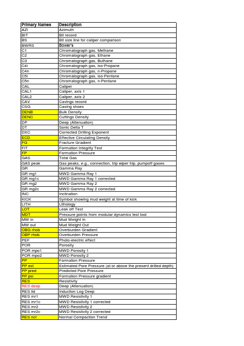
方位
钻头记录
钻头尺寸线,用于井径比较
色谱气体,甲烷
色谱气体,乙烷
色谱气体,丁烷
色谱气体,异丙烷
色谱气体,正丙烷
色谱气体,异戊烷
色谱气体,正戊烷
井径
井径,1轴
井径,2轴
掉块、垮塌记录
套管鞋
堆积密度计算的密度
岩屑密度计算的密度
深度(衰减)
声波增量T
修正钻井指数
当量循环密度
破裂梯度
地层完整性测试
地层压力
天然气总量
气体峰值
伽马射线
随钻伽马射线1
随钻伽马射线1修正
随钻伽马射线2
随钻伽马射线2修正
井斜
井涌时泥浆密度符号
岩性
地漏实验:实测破裂压力
实测地层压力
入口泥浆密度
出口泥浆密度
上覆压力梯度
上覆压力
光电效应
孔隙度
随钻孔隙度1
随钻孔隙度2
地层压力
估计孔隙压力(在当前钻孔深度或以上)预测孔隙压力
地层压力梯度
电阻率
感应测井
随钻电阻率1
随钻电阻率1校正
随钻电阻率2
随钻电阻率2校正
用电阻率计算正常压实趋势
测量工具测量的地层压力
岩性体积密度
加德纳方程计算的密度
随钻测量的地层密度
机械钻速
地震速度
泥岩点(利用电阻率或声波计算)自然电位
立管压力
温度数据
扭矩
地层/地层顶部
双向行程时间
地层层速度。
随钻自然伽马_感应测井仪测量因素分析及应用实例
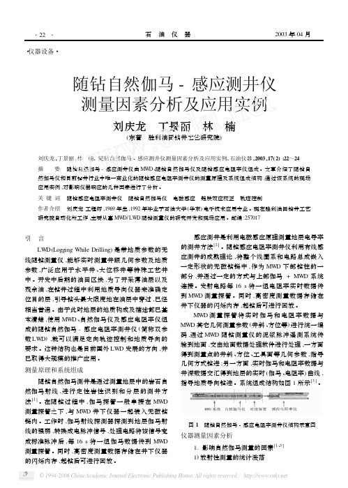
MWD 测 量 探 管 将 实 时 伽 马 和 电 阻 率 数 据 与 MWD 其它几何测量参数 (井斜 、方位等) 进行统一编 码 ,通过 MWD 随钻测量仪的泥浆脉冲遥测系统传 输到地面 ,交由地面数据处理软件进行处理 ,一方面 得到测量点的井斜 、方位 、工具面等几何参数 ,指导 几何方式钻进 ;另一方面 ,实时伽马和电阻率数据与 井深数据交汇得到地层的实时 (伽马 、电阻率) 曲线 , 指导地质导向钻进 。系统组成结构如图 1 所示[3] 。
摘 要 随钻自然伽马 - 感应测井仪由 MWD、随钻自然伽马仪及随钻感应电阻率仪组成 。文章介绍了随钻自
然伽马仪和目前钻井行业中唯一商业化的随钻感应电阻率测井仪的测量原理及系统组成结构 ,通过该系统的现场 应用实例 ,对影响仪器响应的几种因素进行了分析 。
关 键 词 随钻感应电阻率测井仪 随钻自然伽马仪 电磁感应 趋肤效应校正 轨迹控制 作者介绍 刘庆龙 工程师 ,1969 年生 ,1992 年毕业于石油大学 (华东) 电子技术应用专业 。现在胜利油田钻井工艺
与实际参数出现明显差别的重要原因 ,因此 ,必须对
仪器测量的数据进行反褶积处理和趋肤效应校正 ,
从而得到反映地层特性的真实曲线 。所谓趋肤效应
威德福定向钻井技术

1 2 3 4 5 6 7 9
11
13 22 30
1200
Source : Wall Street Journal
WFT portfolio key differentiators: Quality and quantity of patents Fundamental science strength Potential industry impact
•华丽的功能:
•MP4 •Blue tooth •Spotlight •Keyless entry •6 CD’s changer •Reverse Sonar •Leather seats •Wood grain panel
2
© 2006 Weatherford. All rights reserved.
© 2006 Weatherford. All rights reserved.
11
威德福的工具
• 目前已成熟的LWD探头种类有
– 伽马(HGAM) – 方位伽马(HAGR) 及成像 – 能谱方位伽马(SAGR) – 多频电阻率(MFR) – 超深电阻率(MFR+) – 热中子孔隙度(TNP) – 方位密度(NDT)
Mechanical Specifications
Maximum OD Length (HEL System) Weight Top connection Bottom connection Make-up torque Maximum torque Maximum tension Bending strength ratio Maximum dogleg severity, rotating Maximum dogleg severity, sliding Equivalent bending stiffness (OD x ID) Maximum operating temperature Maximum operating pressure Maximum flow rate Maximum sand content 5-1/4 in. 25.2 ft 1,400 lb 3-1/2 IF box 3-1/2 IF pin 9,900 to 10,900 ft-lb 16,700 ft-lb 528,000 lb 2:10 20°/100 ft 36°/100 ft 4.75 in. × 143.22 in. 356°F (180°C) 30,000 psi (207 MPa) 400 gal/min 2%
- 1、下载文档前请自行甄别文档内容的完整性,平台不提供额外的编辑、内容补充、找答案等附加服务。
- 2、"仅部分预览"的文档,不可在线预览部分如存在完整性等问题,可反馈申请退款(可完整预览的文档不适用该条件!)。
- 3、如文档侵犯您的权益,请联系客服反馈,我们会尽快为您处理(人工客服工作时间:9:00-18:30)。
On the other hand, for focused resistivity devices such as the dual laterolog or the MWD toroid sonde the borehole is an essential part of the problem. The tool response is evaluated using a numerical solution to simulate accurately the complex physical situation.
SPWLA Thirtieth Annual Logging Symposium, June 11-14, 1989
,-
INDUCTION,
RESISTIVITY IN HORIZONTAL
AND MWD WELLS
TOOLS
S. Gianzero, R. Chemali and S.M. Su Halliburton Logging Services, Austin, Texas
Dual Induction The borehole has been omitted in the physical model shown in figure 2. Indeed, past experience has shown that the response of an induction tool calculated in such complex geometries does not depend significantly on the inclusion of the borehole in the model. Analytic solutions developed for more general physical situations [Gianzero, 1989], [Anderson, 1986], [Shen, 1986] are then directly applicable to this simplified configuration. The results of the modeling are plotted in figure 2 as a function of the distance separating the axis of the borehole from the horizontal bed boundary. When the dual induction is in the lower formation, far below the boundary, it naturally reads RZOW.,. As the sonde approaches the upper resistive formation, both the medium and the deep measurements sense this medium long before it is reached. After . several feet above the interface, both induction devices read only RUPPer. The distance at which the sonde senses the resistive formation cannot be quan-
SIMULATED LOGS IN A HORIZONTAL NEAR A BED BOUNDARY WELL Two configurations
When drilling horizontally in a reservoir it is generally desirable to stay near the top of the oil or gas zone, immediately below the impervious cap rock. The boundaries between the various media tend to be parallel to each other and parallel to the borehole. If one of the boundaries is close to the wellbore, then its effect is likely to be dominant. Therefore a natural first step towards understanding the response of induction, laterolog and the measurement while drilling toroid sondes in horizontal wells is to simulate their behavior near a single horizontal bed boundary.
INTRODUCTION
N
,,,..
Horizontal wells for exploration and development of oil fields are rapidly gainPrincipally because of the enhanced ing acceptance in many types of reservoirs. recovery, increased penetration of vertical fractures and controlled coning, production is generally more favorable from a single horizontal well than from several vertical wells in a given area [Mahony, 1988]. Horizontal wells even help gather data more effectively to study the geology and the petrophysics in complex fields [De Montigny, 1988]. Furthermore, horizontal drilling is apparently trouble free.
–l-
SPWLA Thktieth Annual Logging Symposium, June 11-14, 1989
.-
This new technology calls naturally for new formation evaluation methods. Since all existing instruments were primarily designed for the traditional geometry of a borehole normal to the beddhg, their response in a situation wherein bed boundaries are more nearly parallel to the borehole axis is of essential importance. This is particularly true for resistivity sondes such as induction, laterolog and measurement while drilling because of their large range of investigation into the formation. In many situations the measurement while drilling sonde or the open hole sondes are strongly influenced by the resistivity of a neighboring shoulder bed. This is a desirable feature if the sonde is used precisely to signal the approaching upper boundary, but is an unwanted source of error if the sonde is run to measure the resistivit y of the formation traversed by the borehole. In any case, mathematical modeling will be applied below to predict the response of standard resistivity devices in the more commonplace situations. will be modeled specifically, first the case of an approaching single bed boundary, then, the situation where the sonde is in the center of a bed surrounded by an upper and a lower shoulders of similar resistivities. For completeness, the case of highly deviated wells will be addressed using recently published modeling techniques.
ABSTቤተ መጻሕፍቲ ባይዱACT
Conventional induction and focused resistivity tools are designed to measure resistivity from a vertical borehole surrounded by a cylindrically invaded zone while minimizing the signal contribution from adjacent horizontal beds. In recent years our understanding of these devices waa extended to include beds exhibiting a large dip relative to the borehole as in the case of a highly deviated well. We shall investigate the applicability of induction and resistivity devices to horizontal wells, where the borehole runs parallel to the bed boundaries. The presence of the borehole may be simply ignored for induction sondes and the tool response is computed via an analytic solution. Because of the relative simplicity of the induction solution, the log response is computed for entire trajectories for the more common radii of curvature used in the drilling process.
