FSB50450中文资料
FSB50250中文资料

FSB50250 Smart Power Module (SPM)May 2005SPMTMFSB50250Smart Power Module (SPM)Features•500V 2.0A 3-phase FRFET inverter including high voltage integrated circuit (HVIC)• 3 divided negative dc-link terminals for inverter current sens-ing applications •HVIC for gate driving and undervoltage protection •3/5V CMOS/TTL compatible, active-high interface •Optimized for low electromagnetic interference •Isolation voltage rating of 1500Vrms for 1min.General DescriptionFSB50250 is a tiny smart power module (SPM TM ) based on FRFET technology as a compact inverter solution for small power motor drive applications such as fan motors and water suppliers. It is composed of 6 fast-recovery MOSFET (FRFET),and 3 half-bridge HVICs for FRFET gate driving. FSB50250provides low electromagnetic interference (EMI) characteristics with optimized switching speed. Moreover, since it employs FRFET as a power switch, it has much better ruggedness and larger safe operation area (SOA) than that of an IGBT-based power module or one-chip solution. The package is optimized for the thermal performance and compactness for the use in the built-in motor application and any other application where the assembly space is concerned. FSB50250 is the most solution for the compact inverter providing the energy efficiency,compactness, and low electromagnetic interference.Absolute Maximum RatingsSymbolParameterConditions RatingUnitsV PN DC Link Input Voltage,Drain-source Voltage of each FRFET 500V I D25Each FRFET Drain Current, Continuous T C = 25°C 1.0A I D80Each FRFET Drain Current, Continuous T C = 80°C0.7A I DP Each FRFET Drain Current, Peak T C = 25°C, PW < 100µs 2.0A P D Maximum Power Dissipation T C = 80°C, For Each FRFET 4.5W V CC Control Supply Voltage Applied between V CC and COM 20V V BS High-side Bias Voltage Applied between VB and V S 20V V IN Input Signal VoltageApplied between IN and COM-0.3 ~ VCC+0.3V T J Operating Junction Temperature -20 ~ 125°C T STG Storage Temperature-50 ~ 150°C R θJC Junction to Case Thermal Resistance Each FRFET under inverter operat-ing condition (Note 1)9.3°C/W V ISOIsolation Voltage60Hz, Sinusoidal, 1 minute, Con-nection pins to heatsink1500V rmsFSB50250 Smart Power Module (SPM)FSB50250 Smart Power Module (SPM)Electrical Characteristics (T J = 25°C, V CC =V BS =15V Unless Otherwise Specified)Inverter Part (Each FRFET Unless Otherwise Specified) Control Part (Each HVIC Unless Otherwise Specified) Note:1.For the measurement point of case temperature T C , please refer to Figure 3 in page 4.2.BV DSS is the absolute maximum voltage rating between drain and source terminal of each FRFET inside SPM. V PN should be sufficiently less than this value considering the effect of the stray inductance so that V DS should not exceed BV DSS in any case.3. t ON and t OFF include the propagation delay time of the internal drive IC. Listed values are measured at the laboratory test condition, and they can be different according to thefield applcations due to the effect of different printed circuit boards and wirings. Please see Figure 4 for the switching time definition with the switching test circuit of Figure 5.4.The peak current and voltage of each FRFET during the switching operation should be included in the safe operating area (SOA). Please see Figure 5 for the RBSOA test cir-cuit that is same as the switching test circuit.SymbolParameter Conditions MinTyp Max UnitsBV DSS Drain-Source BreakdownVoltageV IN = 0V, I D = 250µA (Note 2)500--V ∆BV DSS /∆T J Breakdown Voltage Tem-perature Coefficient I D = 250µA, Referenced to 25°C-0.53-V/°C I DSS Zero Gate Voltage Drain Current V IN = 0V, V DS = 500V--250µA R DS(on)Static Drain-Source On-Resistance V CC = V BS = 15V, V IN = 5V, I D = 0.5A - 3.3 4.0ΩV SD Drain-Source Diode Forward VoltageV CC = V BS = 15V, V IN = 0V, I D = -0.5A -- 1.2V t ON Switching TimesV PN = 300V, V CC = V BS = 15V, I D = 0.5A V IN = 0V ↔ 5V, R EH = 0ΩInductive load L=3mHHigh- and low-side FRFET switching(Note 3)-1273-ns t OFF -800-ns t rr -213-ns E ON -42-µJ E OFF -2.8-µJRBSOAReverse-bias Safe Oper-ating AreaV PN= 400V, V CC = V BS = 15V, I D = I DP , R EH = 0ΩV DS =BV DSS , T J = 125°CHigh- and low-side FRFET switching (Note 4)Full SquareSymbolParameterConditionsMinTyp Max UnitsI QCC Quiescent V CC Current V CC =15V, V IN =0V Applied between V CC and COM --160µA I QBS Quiescent V BS Current V BS =15V, V IN =0VApplied between V B and V S--100µA UV CCD Low-side Undervoltage Protection (Figure 6)V CC Undervoltage Protection Detection Level 7.48.09.4V UV CCR V CC Undervoltage Protection Reset Level 8.08.99.8V UV BSD High-side Undervoltage Protection (Figure 7)V BS Undervoltage Protection Detection Level 7.48.09.4V UV BSR V BS Undervoltage Protection Reset Level 8.08.99.8V V IH ON Threshold Voltage Logic High Level Applied between IN and COM 3.0--V V IL OFF Threshold Voltage Logic Low Level --0.8V I IH Input Bias CurrentV IN = 5V Applied between IN and COM-1020µA I ILV IN = 0V--2µAFSB50250 Smart Power Module (SPM)FSB50250 Smart Power Module (SPM)TRADEMARKSThe following are registered and unregistered trademarks Fairchild Semiconductor owns or is authorized to use and is not intended to be an exhaustive list of all such trademarks.FSB50250 Smart Power Module (SPM)DISCLAIMERFAIRCHILD SEMICONDUCTOR RESERVES THE RIGHT TO MAKE CHANGES WITHOUT FURTHER NOTICE TO ANY PRODUCTS HEREIN TO IMPROVE RELIABILITY, FUNCTION OR DESIGN. FAIRCHILD DOES NOT ASSUME ANY LIABILITY ARISING OUT OF THE APPLICATION OR USE OF ANY PRODUCT OR CIRCUIT DESCRIBED HEREIN; NEITHER DOES IT CONVEY ANY LICENSE UNDER ITS PATENT RIGHTS, NOR THE RIGHTS OF OTHERS.LIFE SUPPORT POLICYFAIRCHILD’S PRODUCTS ARE NOT AUTHORIZED FOR USE AS CRITICAL COMPONENTS IN LIFE SUPPORT DEVICES OR SYSTEMS WITHOUT THE EXPRESS WRITTEN APPROVAL OF FAIRCHILD SEMICONDUCTOR CORPORATION.As used herein:1. Life support devices or systems are devices or systems which,(a) are intended for surgical implant into the body, or (b) support or sustain life, or (c) whose failure to perform when properly used in accordance with instructions for use provided in the labeling,can be reasonably expected to result in significant injury to the user.2. A critical component is any component of a life support device or system whose failure to perform can be reasonably expected to cause the failure of the life support device or system, or to affect its safety or effectiveness.PRODUCT STATUS DEFINITIONS Definition of TermsDatasheet Identification Product Status DefinitionAdvance InformationFormative or In Design This datasheet contains the design specifications for product development. Specifications may change in any manner without notice.PreliminaryFirst ProductionThis datasheet contains preliminary data, andsupplementary data will be published at a later date.Fairchild Semiconductor reserves the right to make changes at any time without notice in order to improve design.No Identification Needed Full ProductionThis datasheet contains final specifications. Fairchild Semiconductor reserves the right to make changes at any time without notice in order to improve design.Obsolete Not In ProductionThis datasheet contains specifications on a product that has been discontinued by Fairchild semiconductor.The datasheet is printed for reference information only.FAST ®FASTr™FPS™FRFET™GlobalOptoisolator™GTO™HiSeC™I 2C™i-Lo ™ImpliedDisconnect™IntelliMAX™ISOPLANAR™LittleFET™MICROCOUPLER™MicroFET™MicroPak™MICROWIRE™MSX™MSXPro™OCX™OCXPro™OPTOLOGIC ®OPTOPLANAR™PACMAN™POP™Power247™PowerEdge™PowerSaver™PowerTrench ®QFET ®QS™QT Optoelectronics™Quiet Series™RapidConfigure™RapidConnect™µSerDes™SILENT SWITCHER ®SMART START™SPM™Stealth™SuperFET™SuperSOT™-3SuperSOT™-6SuperSOT™-8SyncFET™TinyLogic ®TINYOPTO™TruTranslation™UHC™UltraFET ®UniFET™VCX™A CEx™ActiveArray™Bottomless™CoolFET™CROSSVOLT ™DOME™EcoSPARK™E 2CMOS™EnSigna™FACT™FACT Quiet Series™Across the board. Around the world.™The Power Franchise ®Programmable Active Droop™Rev. I15。
IRFP450A中文资料

V D S , D ra in-to-S ource V oltage (V)
QG , Total Gate Charge (nC)
Fig 5. Typical Capacitance Vs. Drain-to-Source Voltage
Fig 6. Typical Gate Charge Vs. Gate-to-Source Voltage
2
元器件交易网
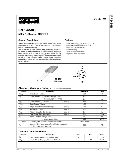
IRFP450A
100
VGS 15V 10V 8.0V 7.0V 6.0V 5.5V 5.0V BOTTOM 4.5V TOP
100
10
I D , Drain-to-Source Current (A)
I D , Drain-to-Source Current (A)
元器件交易网
PD -91884
SMPS MOSFET
IRFP450A
HEXFET® Power MOSFET
Applications l Switch Mode Power Supply ( SMPS ) l Uninterruptable Power Supply l High speed power switching Benefits Low Gate Charge Qg results in Simple Drive Requirement l Improved Gate, Avalanche and Dynamic dv/dt Ruggedness l Fully Characterized Capacitance and Avalanche Voltage and Current l Effective Coss Specified ( See AN 1001)
SCI FSB50650BS 高级动态SPM5系列描述说明书

FSB50650BSFSB50650B / FSB50650BS Motion SPM)5 SeriesDescriptionThe FSB50650B / FSB50650BS is an advanced Motion SPM 5 module providing a fully−featured, highperformance inverter output stage for AC Induction, BLDC and PMSM motors such as refrigerators, fans and pumps. These modules integrate optimized gate drive of the built−in MOSFETs (FRFET technology) to minimize EMI and losses, while also providing multiple on−module protection features including under−voltage lockouts and thermal monitoring. The built−in high−speed HVIC requires only a single supply voltage and translates the incoming logic−level gate inputs to the high−voltage, highcurrent drive signals required to properly drive the module’s internal MOSFETs. Separate open−source MOSFET terminals are available for each phase to support the widest variety of control algorithms.Features•UL Certified No. E209204 (UL1557)•Optimized for over 10 kHz Switching Frequency•500 V FRFET MOSFET 3−Phase Inverter with Gate Drivers and Protection•Built−In Bootstrap Diodes Simplify PCB Layout•Separate Open−Source Pins from Low−Side MOSFETs forThree−Phase Current−Sensing•Active−HIGH Interface, Works with 3.3 / 5 V Logic, Schmitt−trigger Input•Optimized for Low Electromagnetic Interference•HVIC Temperature−Sensing Built−In for Temperature Monitoring •HVIC for Gate Driving and Under−V oltage Protection •Isolation Rating: 1500 V rms/ min.•Moisture Sensitive Level (MSL)3 for SMD•These Devices are Pb−Free and are RoHS CompliantApplications•3−Phase Inverter Driver for Small Power AC Motor DrivesRelated Source•AN−9080 − FSB50450AS − User’s Guide for Motion SPM 5 Series •AN−9082 − Motion SPM5 Series Thermal Performance by Contact PressureSPM5E−023 / 23LD, PDD STDCASE MODEJSee detailed ordering and shipping information on page 2 of this data sheet.ORDERING INFORMATION$Y= ON Semiconductor Logo&Z= Assembly Plant Code&3= Data Code (Year & Week) &K= LotFSB50650X= Specific Device Code⇒ X = B or BSMARKING DIAGRAM$YFSB50650X&Z&K&E&E&E&3SPM5H−023 / 23LD, PDD STD,SPM23−BDCASE MODEMPACKAGE MARKING AND ORDERING INFORMATIONDevice Device Marking Package Packing Type Reel Size Quantity FSB50650B FSB50650B SPM5P−023Rail NA15FSB50650BS FSB50650BS SPM5Q−023Tape & Reel330 mm450ABSOLUTE MAXIMUM RATINGS (T C = 25°C, Unless otherwise noted)Symbol Parameter Conditions Rating Unit INVERTER PART(Each MOSFET Unless Otherwise Specified)V DSS Drain−Source Voltage of Each MOSFET500V *I D25Each MOSFET Drain Current, Continuous T C= 25°C 4.0A *I D80Each MOSFET Drain Current, Continuous T C= 80°C 2.5A *I DP Each MOSFET Drain Current, Peak T C= 25°C, PW < 100 m s10.3A *I DRMS Each MOSFET Drain Current, Rms T C= 80°C, F PWM< 20 kHz 1.8A rms CONTROL PART(Each HVIC Unless Otherwise Specified)V DD Control Supply Voltage Applied Between V DD and COM20V V BS High−side Bias Voltage Applied Between V B and V S20V V IN Input Signal Voltage Applied Between IN and COM−0.3 ~ V DD+0.3V BOOTSTRAP DIODE PART(Each Bootstrap Diode Unless Otherwise Specified.)V RRMB Maximum Repetitive Reverse Voltage500V * I FB Forward Current T C= 25°C0.5A * I FPB Forward Current (Peak)T C= 25°C, Under 1 ms Pulse Width 2.0A THERMAL RESISTANCEInverter MOSFET part, (Per Module) 2.1°C/W R th(j−c)Q Junction to Case Thermal Resistance(Note 1)TOTAL SYSTEMT J Operating Junction Temperature−40 ~ 150°C T STG Storage Temperature−40 ~ 125°C1500V rms V ISO Isolation Voltage60 Hz, Sinusoidal, 1 minute,Connection Pins to HeatsinkStresses exceeding those listed in the Maximum Ratings table may damage the device. If any of these limits are exceeded, device functionality should not be assumed, damage may occur and reliability may be affected.1.For the Measurement Point of Case Temperature T C, Please refer to Figure 4.2.Marking “ * ” Is Calculation Value or Design Factor.ing continuously under heavy loads or excessive assembly conditions (e.g. the application of high temperature/ current/ voltage and thesignificant change in temperature, etc.) may cause this product to decrease in the reliability significantly even if the operating conditions(i.e. operating temperature/ current/ voltage, etc.) are within the absolute maximum ratings and the operating ranges.PIN DESCRIPTIONPin No.Pin Name Pin Description1COM IC Common Supply Ground2V B(U)Bias Voltage for U Phase High Side FRFET Driving 3V DD(U)Bias Voltage for U Phase IC and Low Side FRFET Driving 4IN (UH)Signal Input for U Phase High −side 5IN (UL)Signal Input for U Phase Low −side 6N.C N.C7V B(V)Bias Voltage for V Phase High Side FRFET Driving 8V DD(V)Bias Voltage for V Phase IC and Low Side FRFET Driving 9IN (VH)Signal Input for V Phase High −side 10IN (VL)Signal Input for V Phase Low −side 11V TS Output for HVIC Temperature Sensing12V B(W)Bias Voltage for W Phase High Side FRFET Driving 13V DD(W)Bias Voltage for W Phase IC and Low Side FRFET Driving 14IN (WH)Signal Input for W Phase High −side 15IN (WL)Signal Input for W Phase Low −side 16N.C N.C17P Positive DC–Link Input18U, V S(U)Output for U Phase & Bias Voltage Ground for High Side FRFET Driving 19N U Negative DC–Link Input for U Phase 20N V Negative DC–Link Input for V Phase21V, V S(V)Output for V Phase & Bias Voltage Ground for High Side FRFET Driving 22N W Negative DC–Link Input for W Phase23W, V S(W)Output for W Phase & Bias Voltage Ground for High Side FRFET DrivingFigure 1. Pin Configuration and Internal Block Diagram (Bottom View)4.Source T erminal of Each Low −Side MOSFET is Not Connected to Supply Ground or Bias Voltage Ground Inside Motion SPM 5 product. External Connections Should be Made as Indicated in Figure 3.(1) COM (2) V (3) V (4) IN (5) IN (7) V (11) V (8) V (9) IN (10) IN (12) V (13) V (14) IN (15) IN (16) N.C(17) P(18) U, V S(U)(19) N U(20) N V (21) V, V S(V)(22) N W (23) W, V S(W)ELECTRICAL CHARACTERISTICS (T J = 25°C, V DD = V BS = 15 V Unless Otherwise Specified)Symbol Parameter Test Conditions Min.Typ.Max.Unit INVERTER PART (Each MOSFET Unless Otherwise Specified)BV DSS Drain−Source Breakdown Voltage V IN= 0 V, I D= 1 mA ( Note 5)500−−VI DSS Zero Gate Voltage Drain Current V IN= 0 V, V DS= 500 V−−1mA R DS(on)Static Drain−Source On−Resistance V DD= V BS= 15 V, V IN= 5 V, I D= 1.5 A− 1.43 1.8W V SD Drain−Source Diode Forward Voltage V DD= V BS= 15 V, V IN= 0 V, I D= −1.5 A−− 1.1Vt ON Switching Times V PN= 300 V, V DD= V BS= 15 V, I D= 1.5 AV IN= 0 V ↔5 V, Inductive Load L = 3 mH High−and Low−Side MOSFET Switching(Note 6)−440−nst OFF−580−ns t rr−100−nsE ON−30−m JE OFF−11−m J RBSOA Reverse−Bias Safe Operating Area V PN= 400 V, V DD= V BS= 15 V, I D= I DP,V DS= BV DSS, T J= 150°CHigh− and Low−Side MOSFET Switching (Note 7)Full Square CONTROL PART (Each HVIC Unless Otherwise Specified)I QDD Quiescent V DD Current V DD= 15 V, V IN= 0 V Applied Between V DD andCOM−−200m AI QBS Quiescent V BS Current V BS= 15 V, V IN= 0 V Applied BetweenV B(U)−U, V B(V)−V,V B(W)−W−−100m AI PDD Operating V DD Supply V DD− COM V DD = 15 V,f PWM = 20 kHz,Duty = 50%, Applied toOne PWM Signal Inputfor Low−Side−−900m AI PBS Operating V BS Supply Current V B(U)− V S(U), V B(V)− V S(V), V B(W)− V S(W)V DD = V BS = 15 V,f PWM= 20 kHz,Duty = 50%, Applied toOne PWM Signal Inputfor High−Side−−800m AUV DDD Low−Side Undervoltage Protection(Figure 8)V DD Undervoltage Protection Detection Level7.48.09.4VUV DDR V DD Undervoltage Protection Reset Level8.08.99.8VUV BSD High−Side Undervoltage Protection(Figure 9)V BS Undervoltage Protection Detection Level7.48.09.4VUV BSR V BS Undervoltage Protection Reset Level8.08.99.8V V TS HVIC Temperature sensing voltageoutputV DD= 15 V, T HVIC= 25°C (Note 8)600790980mVV IH ON Threshold Voltage Logic High Level Applied between IN andCOM −− 2.9VV IL OFF Threshold Voltage Logic Low Level0.8−−V BOOTSTRAP DIODE PART (Each Bootstrap Diode Unless Otherwise Specified)V FB Forward Voltage I F= 0.1 A, T C= 25°C (Note 9)− 2.5−V t rrB Reverse Recovery Time I F= 0.1 A, T C= 25°C−80−ns Product parametric performance is indicated in the Electrical Characteristics for the listed test conditions, unless otherwise noted. Product performance may not be indicated by the Electrical Characteristics if operated under different conditions.RECOMMENDED OPERATING CONDITIONSymbol ParameterConditionsMin.Typ.Max.Unit V PN Supply Voltage Applied between P and N −300400V V DD Control Supply Voltage Applied between V DD and COM 13.515.016.5V V BS High −Side Bias Voltage Applied between V B and V S 13.515.016.5V V IN(ON)Input ON Threshold Voltage Applied between V IN and COM3.0−V DD V V IN(OFF)Input OFF Threshold Voltage0−0.6V t dead Blanking Time for Preventing Arm −Short V DD = V BS = 13.5 ~ 16.5 V, T J ≤ 150°C 1.0−−m s f PWMPWM Switching FrequencyT J ≤ 150°C−15−kHz12347891011121314150.00.10.20.30.40.50.60.70.80.91.0Built in Bootstrap Diode V F −I F CharacteristicT C = 255CFigure 2. Built in Bootstrap Diode Characteristics (Typical)V F [V]56I F [A ]NOTES:5.BV DSS is the Absolute Maximum Voltage Rating Between Drain and Source T erminal of Each MOSFET Inside Motion SPM 5 product. V PNShould be Sufficiently Less Than This Value Considering the Effect of the Stray Inductance so that V DS Should Not Exceed BV DSS in Any Case.6.t ON and t OFF Include the Propagation Delay Time of the Internal Drive IC. Listed Values are Measured at the Laboratory T est Condition, and They Can be Different According to the Field Applications Due to the Effect of Different Printed Circuit Boards and Wirings. Please see Figure 6 for the Switching Time Definition with the Switching T est Circuit of Figure7.7.The peak current and voltage of each MOSFET during the switching operation should be included in the Safe Operating Area (SOA). Please see Figure 8 for the RBSOA test circuit that is same as the switching test circuit.8.V TS is only for sensing temperature of module and cannot shutdown MOSFET s automatically.9.Built in bootstrap diode includes around 15 W resistance characteristic. Please refer to Figure 1.HINLIN Output Note 00Z Both FRFET Off 010Low side FRFET On 10High side FRFET On11ForbiddenShoot through OpenOpenZSame as (0,0)These values depend on PWM control algorithmFigure 3. Recommended MCU Interface and Bootstrap Circuit with ParametersV DC 10.Parameters for bootstrap circuit elements are dependent on PWM algorithm. For 15 kHz of switching frequency, typical example of parameters is shown above.11.RC −coupling (R 5 and C 5) and C 4 at each input of Motion SPM 5 product and MCU (Indicated as Dotted Lines) may be used to prevent improper signal due to surge −noise.12.Bold lines should be short and thick in PCB pattern to have small stray inductance of circuit, which results in the reduction of surge −voltage.Bypass capacitors such as C 1, C 2 and C 3 should have good high −frequency characteristics to absorb high −frequency ripple −current.Figure 4. Case Temperature Measurement13.Attach the thermocouple on top of the heat −sink of SPM 5 package (between SPM 5 package and heatsink if applied) to get the correct temperature measurement.204060801001201401600.51.01.52.02.53.03.5T HVIC [°C]Figure 5. Temperature Profile of V TS (Typical)V T S [V ](a) Turn −on(b) Turn −offFigure 6. Switching Time DefinitionsFigure 7. Switching and RBSOA (Single −Pulse) Test Circuit (Low −side)C V V VInput Signal UV Protection StatusLow −side Supply, V MOSFET CurrentInput Signal UV ProtectionStatusHigh −side Supply, V MOSFET CurrentFigure 9. Under −Voltage Protection (High −Side)14.About pin position, refer to Figure 1.15.RC−coupling (R5and C5, R4and C6) and C4at each input of Motion SPM 5 product and MCU are useful to prevent improper inputsignal caused by surge−noise.16.The voltage−drop across R3affects the low−side switching performance and the bootstrap characteristics since it is placed betweenCOM and the source terminal of the low−side MOSFET. For this reason, the voltage−drop across R3should be less than 1 V in the steady−state.17.Ground−wires and output terminals, should be thick and short in order to avoid surge−voltage and malfunction of HVIC.18.All the filter capacitors should be connected close to Motion SPM 5 product, and they should have good characteristics for rejectinghigh−frequency ripple current.Figure 10. Example of Application CircuitPACKAGE DIMENSIONSSPM5H−023 / 23LD, PDD STD, SPM23−BD (Ver1.5) SMD TYPECASE MODEMISSUE O10SPM5E −023 / 23LD, PDD STD, FULL PACK, DIP TYPE CASE MODEJISSUE OSPM is a registered trademarks of Semiconductor Components Industries, LLC (SCILLC) or its subsidiaries in the United States and/or otherON Semiconductor and are trademarks of Semiconductor Components Industries, LLC dba ON Semiconductor or its subsidiaries in the United States and/or other countries.ON Semiconductor owns the rights to a number of patents, trademarks, copyrights, trade secrets, and other intellectual property. A listing of ON Semiconductor’s product/patent coverage may be accessed atON Semiconductor makes no warranty, representation or guarantee regarding the suitability of its products for any particular purpose, nor does ON Semiconductor assume any liability arising out of the application or use of any product or circuit, and specifically disclaims any and all liability, including without limitation special, consequential or incidental damages.PUBLICATION ORDERING INFORMATIONFSB50650BS。
FF450R12KE4中文资料

Diode-Wechselrichter / diode-inverter
9 0 0+ 9 ? 3g : $ @ # ! $ : @ ;( ,< ( ,< ( ,1 ; ( ,1 ; ( # : ! $ $
Vorläufige Daten preliminary data
,<<= 3f 3f<= 7) > 7 , 8 8 8g 8g E 1 )
,B. u,v
0
100 200 300 400 500 600 700 800 900
3- u8v
4
元器件交易网
Technische Information / technical information
IGBT-Module IGBT-modules
FF450R12KE4
3- ( 7) 81 ,-. ( J ,1 V/ ( O ,B. ( X ) ,1 D ( > 8DL U%&'( ) *+W B54 ( 1 N
"54
$
9
%&' ( )*+ 3- ( 7) 81 ,-. ( J ,1 V/ ( O ,B. ( X ) ,1 D ( 7 ,DL U%&'( ) *+W %&' ( )*+ %&' ( ) *+ B5ZZ ( 1 N ,B. \ ) ,1 ,-- ( , ,-.6H] ( ,-./ VG-. ^ D 3?`% D ! 3?`% cdSPHGP ( DU ^ W ;\ L 1 %&' ( ) *+
Vorläufige Daten preliminary data
IRFS450中文资料
(Note 4)(Note 4, 5)(Note 4, 5) (Note 4)Notes:1. Repetitive Rating : Pulse width limited by maximum junction temperature2. L = 19.3mH, I AS = 9.6A, V DD = 50V, R G = 25 Ω, Starting T J = 25°C3. I SD ≤ 14A, di/dt ≤ 300A/µs, V DD ≤ BV DSS, Starting T J = 25°C4. Pulse Test : Pulse width ≤300µs, Duty cycle ≤2%5. Essentially independent of operating temperatureBV DSS Drain-Source Breakdown Voltage V GS = 0 V, I D = 250 µA500----V ∆BV DSS / ∆T J Breakdown Voltage Temperature CoefficientI D = 250 µA, Referenced to 25°C --0.55--V/°C I DSS Zero Gate Voltage Drain Current V DS = 500 V, V GS = 0 V ----10µA V DS = 400 V, T C = 125°C ----100µA I GSSF Gate-Body Leakage Current, Forward V GS = 30 V, V DS = 0 V ----100nA I GSSRGate-Body Leakage Current, ReverseV GS = -30 V, V DS = 0 V-----100nAOn CharacteristicsV GS(th)Gate Threshold Voltage V DS = V GS , I D = 250 µA 2.0-- 4.0V R DS(on)Static Drain-Source On-ResistanceV GS = 10 V, I D = 4.8 A --0.310.39Ωg FSForward TransconductanceV DS = 40 V, I D = 4.8 A--11.5--SDynamic CharacteristicsC iss Input Capacitance V DS = 25 V, V GS = 0 V, f = 1.0 MHz--29003800pF C oss Output Capacitance--260340pF C rssReverse Transfer Capacitance--6080pFSwitching Characteristicst d(on)Turn-On Delay Time V DD = 250 V, I D = 14 A,R G = 25 Ω--45100ns t r Turn-On Rise Time --130270ns t d(off)Turn-Off Delay Time --260530ns t f Turn-Off Fall Time --125260ns Q g Total Gate Charge V DS = 400 V, I D = 14 A,V GS = 10 V--87113nC Q gs Gate-Source Charge --13--nC Q gdGate-Drain Charge--39--nCDrain-Source Diode Characteristics and Maximum RatingsI S Maximum Continuous Drain-Source Diode Forward Current ----9.6A I SM Maximum Pulsed Drain-Source Diode Forward Current----38.4A V SD Drain-Source Diode Forward Voltage V GS = 0 V, I S = 9.6 A ---- 1.4V t rr Reverse Recovery Time V GS = 0 V, I S = 14 A,dI F / dt = 100 A/µs--495--ns Q rrReverse Recovery Charge--7.66--µCDISCLAIMERFAIRCHILD SEMICONDUCTOR RESERVES THE RIGHT TO MAKE CHANGES WITHOUT FURTHER NOTICE TO ANY PRODUCTS HEREIN TO IMPROVE RELIABILITY, FUNCTION OR DESIGN. FAIRCHILD DOES NOT ASSUME ANY LIABILITY ARISING OUT OF THE APPLICATION OR USE OF ANY PRODUCT OR CIRCUIT DESCRIBED HEREIN;NEITHER DOES IT CONVEY ANY LICENSE UNDER ITS PATENT RIGHTS, NOR THE RIGHTS OF OTHERS.LIFE SUPPORT POLICYFAIRCHILD’S PRODUCTS ARE NOT AUTHORIZED FOR USE AS CRITICAL COMPONENTS IN LIFE SUPPORT DEVICES OR SYSTEMS WITHOUT THE EXPRESS WRITTEN APPROVAL OF FAIRCHILD SEMICONDUCTOR CORPORATION.As used herein:1. Life support devices or systems are devices or systems which, (a) are intended for surgical implant into the body,or (b) support or sustain life, or (c) whose failure to perform when properly used in accordance with instructions for use provided in the labeling, can be reasonably expected to result in significant injury to the user.2. A critical component is any component of a life support device or system whose failure to perform can be reasonably expected to cause the failure of the life support device or system, or to affect its safety or effectiveness.PRODUCT STATUS DEFINITIONS Definition of TermsDatasheet Identification Product Status DefinitionAdvance InformationFormative or In Design This datasheet contains the design specifications for product development. Specifications may change in any manner without notice.PreliminaryFirst ProductionThis datasheet contains preliminary data, andsupplementary data will be published at a later date.Fairchild Semiconductor reserves the right to make changes at any time without notice in order to improve design.No Identification Needed Full ProductionThis datasheet contains final specifications. Fairchild Semiconductor reserves the right to make changes at any time without notice in order to improve design.Obsolete Not In ProductionThis datasheet contains specifications on a product that has been discontinued by Fairchild semiconductor.The datasheet is printed for reference information only.TRADEMARKSThe following are registered and unregistered trademarks Fairchild Semiconductor owns or is authorized to use and is not intended to be an exhaustive list of all such trademarks.STAR*POWER is used under licenseACEx™Bottomless™CoolFET™CROSSVOLT ™DenseTrench™DOME™EcoSPARK™E 2CMOS™EnSigna™FACT™FACT Quiet Series™FAST ®FASTr™FRFET™GlobalOptoisolator™GTO™HiSeC™ISOPLANAR™LittleFET™MicroFET™MicroPak™MICROWIRE™OPTOLOGIC™OPTOPLANAR™PACMAN™POP™Power247™PowerTrench ®QFET™QS™QT Optoelectronics™Quiet Series™SLIENT SWITCHER ®SMART START™STAR*POWER™Stealth™SuperSOT™-3SuperSOT™-6SuperSOT™-8SyncFET™TruTranslation™TinyLogic™UHC™UltraFET ®VCX™。
CPU内存FSB
外频CPU的外频,通常为系统总线的工作频率(系统时钟频率),CPU与周边设备传输数据的频率,具体是指CPU到芯片组之间的总线速度。
外频是CPU与主板之间同步运行的速度,而且目前的绝大部分电脑系统中外频,也是内存与主板之间的同步运行的速度,在这种方式下,可以理解为CPU的外频直接与内存相连通,实现两者间的同步运行状态。
在486之前,CPU的主频还处于一个较低的阶段,CPU的主频一般都等于外频。
而在486出现以后,由于CPU工作频率不断提高,而PC机的一些其他设备(如插卡、硬盘等)却受到工艺的限制,不能承受更高的频率,因此限制了CPU频率的进一步提高。
因此出现了倍频技术,该技术能够使CPU内部工作频率变为外部频率的倍数,从而通过提升倍频而达到提升主频的目的。
倍频技术就是使外部设备可以工作在一个较低外频上,而CPU主频是外频的倍数。
在Pentium时代,CPU的外频一般是60/66MHz,从Pentium Ⅱ350开始,CPU外频提高到100MHz,目前CPU外频已经达到了200MHz。
由于正常情况下CPU总线频率和内存总线频率相同,所以当CPU外频提高后,与内存之间的交换速度也相应得到了提高,对提高电脑整体运行速度影响较大。
倍频使获得频率为原频率整数倍的方法。
利用非线性器件从原频率产生多次谐波,通过带通滤波器选出所需倍数的那次谐波。
在数字电路中则利用逻辑门来实现倍频。
倍频系数是指CPU主频与外频之间的相对比例关系。
在相同的外频下,倍频越高CPU 的频率也越高。
但实际上,在相同外频的前提下,高倍频的CPU本身意义并不大。
这是因为CPU与系统之间数据传输速度是有限的,一味追求高倍频而得到高主频的CPU就会出现明显的“瓶颈”效应——CPU从系统中得到数据的极限速度不能够满足CPU运算的速度。
CPU的倍频,全称是倍频系数。
CPU的核心工作频率与外频之间存在着一个比值关系,这个比值就是倍频系数,简称倍频。
理论上倍频是从1.5一直到无限的,但需要注意的是,倍频是以0.5为一个间隔单位。
芯片说明书:Fairchild Semiconductor FSB50450 Motion SPM

FSB50450 Motion SPM® 5 FRFET® SeriesApril 2013FSB50450Motion SPM ® 5 FRFET ® SeriesFeatures•500 V R DS(on)= 2.4Ω (Max ) FRFET MOSFET 3-Phase Inverter Including HVICs •Three Separate Negative DC-Link Terminals for Inverter Current Sensing Applications •HVIC for Gate Driving and Undervoltage Protection •Active-High Interface, Can Work With 3.3 V / 5 V Logic •Optimized for Low Electromagnetic Interference •Isolation Voltage Rating of 1500 Vrms for 1 min.Applications•3-Phase Inverter Driver for Small Power AC Motor DrivesGeneral DescriptionFSB50450 is a Motion SPM5 Series Based on Fast-Recovery MOSFET(FRFET) Technology as a Compact Inverter Solution for Small Power Motor Drive Applications Such as Fans and Pumps. It is Composed of Six FRFET MOSFETs and Three Half-Bridge Gate Drive HVICs. FSB50450 Provides Low Electromagnetic Interference(EMI) Characteristics with Optimizing Switching Speed. Moreover, Since It Employs MOSFETs as Power Switches, It has Greater Ruggedness and a Larger Safe Operating Area(SOA) than IGBT-Based Power Modules. The Pakage is Optimized for Thermal Performance and Compactness for use in Applications Where Space is Limited. FSB50450 is the Right Solution for Inverters Requiring Energy Efficiency, Compact-ness, and Low Electromanetic Interference.Related Source•AN9042 : Motion SPM5 Series Ver.1 User’s Guide •AN-9082 : Motion SPM5 Series Thermal Performance by Contact PressurePackage Marking & Ordering InformationDevice MarkingDevicePackageReel SizePacking TypeQuantityFSB50450FSB50450SPM5B-023-RAIL15Thermal Resistance Total System Note:1. For the Measurement Point of Case Temperature T C , Please refer to Figure 4.2. Marking “ * “ Is Calculation Value or Design Factor.SymbolParameterConditionsRatingUnitR θJCJunction to Case Thermal ResistanceEach MOSFET under Inverter Oper-ating Condition (Note 1)8.9°C/WSymbolParameterConditions RatingUnitT J Operating Junction Temperature -20 ~ 150°C T STG Storage Temperature -50 ~ 150°C V ISOIsolation Voltage60 Hz, Sinusoidal, 1 minute, Con-nection Pins to Heatsink1500V rmsControl Part (Each HVIC Unless Otherwise Specified) Note:1.BV DSS is the Absolute Maximum Voltage Rating Between Drain and Source Terminal of Each MOSFET Inside Motion SPM ®. V PN Should be Sufficiently Less Than This Value Considering the Effect of the Stray Inductance so that V DS Should Not Exceed BV DSS in Any Case.2. t ON and t OFF Include the Propagation Delay Time of the Internal Drive IC. Listed Values are Measured at the Laboratory Test Condition, and They Can be Different Accordingto the Field Applications Due to the Effect of Different Printed Circuit Boards and Wirings. Please see Figure 4 for the Switching Time Definition with the Switching Test Circuit of Figure 5.3. The peak current and voltage of each MOSFET during the switching operation should be included in the safe operating area (SOA). Please see Figure 5 for the RBSOA testcircuit that is same as the switching test circuit.E OFF -11-µJRBSOAReverse-Bias Safe Oper-ating AreaV PN= 400 V, V CC = V BS = 15 V, I D = I DP , V DS =BV DSS ,T J = 150°CHigh- and Low-Side MOSFET Switching (Note 3)Full SquareSymbolParameterConditionsMinTyp MaxUnitI QCC Quiescent V CC Current V CC =15 V, V IN =0V Applied Between V CC and COM--160µA I QBS Quiescent V BS Current V BS =15 V, V IN =0VApplied Between V B(U)-U, V B(V)-V, V B(W)-W--100µA UV CCD Low-Side Undervoltage Protection (Figure 6)V CC Undervoltage Protection Detection Level 7.48.09.4V UV CCR V CC Undervoltage Protection Reset Level 8.08.99.8V UV BSD High-Side Undervoltage Protection (Figure 7)V BS Undervoltage Protection Detection Level 7.48.09.4V UV BSR V BS Undervoltage Protection Reset Level 8.08.99.8V V IH ON Threshold Voltage Logic High Level Applied between IN and COM 3.0--V V IL OFF Threshold Voltage Logic Low Level --0.8V I IH Input Bias CurrentV IN = 5V Applied between IN and COM-1020µA I ILV IN = 0V--2µAFSB50450 Motion SPM® 5 FRFET® Series* EZSWITCH™ and FlashWriter ® are trademarks of System General Corporation, used under license by Fairchild Semiconductor.DISCLAIMERFAIRCHILD SEMICONDUCTOR RESERVES THE RIGHT TO MAKE CHANGES WITHOUT FURTHER NOTICE TO ANY PRODUCTS HEREIN TO IMPROVE RELIABILITY, FUNCTION, OR DESIGN. FAIRCHILD DOES NOT ASSUME ANY LIABILITY ARISING OUT OF THE APPLICATION OR USE OF ANY PRODUCT OR CIRCUIT DESCRIBED HEREIN; NEITHER DOES IT CONVEY ANY LICENSE UNDER ITS PATENT RIGHTS, NOR THE RIGHTS OF OTHERS.THESE SPECIFICATIONS DO NOT EXPAND THE TERMS OF FAIRCHILD’S WORLDWIDE TERMS AND CONDITIONS, SPECIFICALLY THE WARRANTY THEREIN, WHICH COVERS THESE PRODUCTS.LIFE SUPPORT POLICYFAIRCHILD’S PRODUCTS ARE NOT AUTHORIZED FOR USE AS CRITICAL COMPONENTS IN LIFE SUPPORT DEVICES OR SYSTEMS WITHOUT THE EXPRESS WRITTEN APPROVAL OF FAIRCHILD SEMICONDUCTOR CORPORATION.As used herein:1. Life support devices or systems are devices or systems which, (a) areintended for surgical implant into the body or (b) support or sustain life,and (c) whose failure to perform when properly used in accordance with instructions for use provided in the labeling, can be reasonably expected to result in a significant injury of the user.2.A critical component in any component of a life support, device, system whose failure to perform can be reasonably expected to cause the failure of the life support device or system, or to affect its safety or effectiveness.PRODUCT STATUS DEFINITIONS Definition of TermsBuild it Now™CorePLUS™CorePOWER™CROSSVOLT ™CTL™Current Transfer Logic™EcoSPARK ®EfficentMax™EZSWITCH™ *™Fairchild ®Fairchild Semiconductor ®FACT Quiet Series™FACT ®FAST ®FastvCore™FlashWriter ® *FPS™F-PFS™FRFET ®Global Power Resource SM Green FPS™Green FPS™ e-Series™GTO™IntelliMAX™ISOPLANAR™MegaBuck™MICROCOUPLER™MicroFET™MicroPak™MillerDrive™MotionMax™Motion-SPM™OPTOLOGIC ®OPTOPLANAR ®®PDP SPM™Power-SPM™PowerTrench ®PowerXS™Programmable Active Droop™QFET ®QS™Quiet Series™RapidConfigure™™Saving our world, 1mW /W /kW at a time™SmartMax™SMART START™SPM ®STEALTH™SuperFET™SuperSOT™-3SuperSOT™-6SuperSOT™-8SupreMOS™SyncFET™®The Power Franchise ®TinyBoost™TinyBuck™TinyLogic ®TINYOPTO™TinyPower™TinyPWM™TinyWire™TriFault Detect™µSerDes™UHC ®Ultra FRFET™UniFET™VCX™VisualMax™XS™®Datasheet Identification Product Status DefinitionAdvance InformationFormative / In DesignDatasheet contains the design specifications for product development. Specifications may change in any manner without notice.ANTI-COUNTERFEITING POLICYFairchild Semiconductor Corporation’s Anti-Counterfeiting Policy. Fairchild’s Anti-Counterfeiting Policy is also stated on our external website,, under Sales Support .Counterfeiting of semiconductor parts is a growing problem in the industry. All manufactures of semiconductor products are experiencing counterfeiting of their parts. Customers who inadvertently purchase counterfeit parts experience many problems such as loss of brand reputation, substandard performance, failed application, and increased cost of production and manufacturing delays. Fairchild is taking strong measures to protect ourselves and our customers from the proliferation of counterfeit parts. Fairchild strongly encourages customers to purchase Fairchild parts either directly from Fairchild or from Authorized Fairchild Distributors who are listed by country on our web page cited above. Products customers buy either from fairchild directly or from Authorized Fairchild Distributors are genuine parts, have full traceability, meet Fairchild’s quality standards for handing and storage and provide access to Fairchild’s full range of up-to-date technical and product information. Fairchild and our Authorized Distributors will stand behind all warranties and will appropriately address and warranty issues that may arise. Fairchild will not provide any warranty coverage or other assistance for parts bought from Unauthorized Sources. Fairchild is committed to combat this global problem and encourage our customers to do their part in stopping this practice by buying direct or from authorized distributors.。
DP450系列数字面板表示器产品说明书
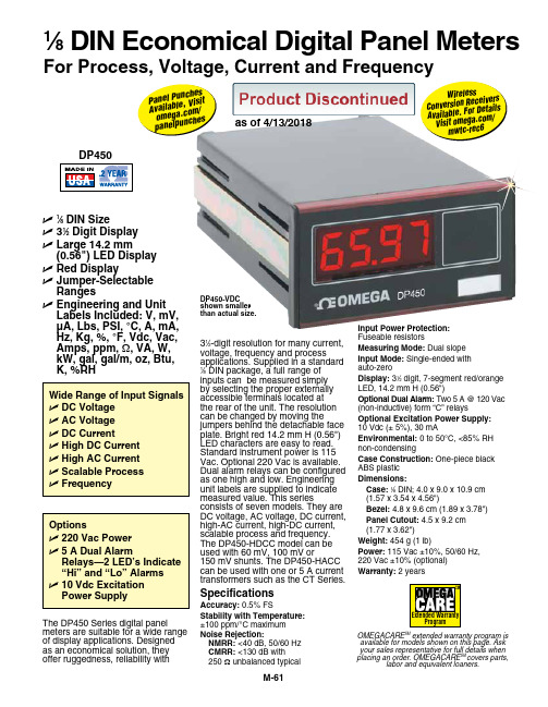
U1⁄8 DIN SizeU 31⁄2 Digit DisplayU L arge 14.2 mm(0.56") LED Display U Red DisplayU J umper-SelectableRangesU E ngineering and Unit Labels Included: V, mV,µA, Lbs, PSI, °C, A, mA,Hz, Kg, %, °F, Vdc, Vac,Amps, ppm, Ω, VA, W,kW, gal, gal/m, oz, Btu,K, %RHThe DP450 Series digital panel meters are suitable for a wide range of display applications. Designed as an economical solution, they offer ruggedness, reliability with DP450-VDC shown smaller than actual size.1⁄8 DIN Economical Digital Panel MetersFor Process, Voltage, Current and FrequencySpecificationsAccuracy: 0.5% FSStability with Temperature:±100 ppm/°C maximumNoise Rejection:NMRR: <40 dB, 50/60 HzCMRR: <130 dB with250 Ω unbalanced typicalInput Power Protection:Fuseable resistorsMeasuring Mode: Dual slopeInput Mode: Single-ended withauto-zeroDisplay: 31⁄2 digit, 7-segment red/orangeLED, 14.2 mm H (0.56")Optional Dual Alarm: Two 5 A @ 120 Vac(non-inductive) form “C” relaysOptional Excitation Power Supply:10 Vdc (± 5%), 30 mAEnvironmental: 0 to 50°C, <85% RHnon-condensingCase Construction: One-piece blackABS plasticDimensions:Case:1⁄8 DIN; 4.0 x 9.0 x 10.9 cm(1.57 x 3.54 x 4.56")Bezel: 4.8 x 9.6 cm (1.89 x 3.78")Panel Cutout: 4.5 x 9.2 cm(1.77 x 3.62")Weight: 454 g (1 lb)Power: 115 Vac ±10%, 50/60 Hz,220 Vac ±10% (optional)Warranty: 2 years31⁄2-digit resolution for many current,voltage, frequency and processapplications. Supplied in a standard1⁄8 DIN package, a full range ofinputs can be measured simplyby selecting the proper externallyaccessible terminals located atthe rear of the unit. The resolutioncan be changed by moving thejumpers behind the detachable faceplate. Bright red 14.2 mm H (0.56")LED characters are easy to read.Standard instrument power is 115Vac. Optional 220 Vac is available.Dual alarm relays can be configuredas one high and low. Engineeringunit labels are supplied to indicatemeasured value. This seriesconsists of seven models. They areDC voltage, AC voltage, DC current,high-AC current, high-DC current,scalable process and frequency.The DP450-HDCC model can beused with 60 mV, 100 mV or150 mV shunts. The DP450-HACCcan be used with one or 5 A currenttransformers such as the CT Series.OMEGACARE SM extended warranty program isavailable for models shown on this page. Askyour sales representative for full details whenplacing an order. OMEGACARE SM covers parts,labor and equivalent loaners.W i r e l e s sC o n v e r s i o n R ec e i v e r sA v a i l a b l e.F o rD e t a i l sV i s i t o m e g a.co m/m w t c-r e c6P a n e l P un c h e sA v a i l a b l e,V i s i to m e g a.c om/p a n e l p u nc h e s as of 4/13/2018Ordering Examples: DP450-E-A2-220VAC, process meter with red display, dual relay output and 220 Vac power.OCW-3 OMEGACARE SM extends standard 2-year warranty to a total of 5 years.DP450-F, frequency meter with red display.DP450 Inputs and Ranges。
- 1、下载文档前请自行甄别文档内容的完整性,平台不提供额外的编辑、内容补充、找答案等附加服务。
- 2、"仅部分预览"的文档,不可在线预览部分如存在完整性等问题,可反馈申请退款(可完整预览的文档不适用该条件!)。
- 3、如文档侵犯您的权益,请联系客服反馈,我们会尽快为您处理(人工客服工作时间:9:00-18:30)。
FSB50450 Smart Power Module (SPM)May 2005SPMTMFSB50450Smart Power Module (SPM)Features•500V 3.0A 3-phase FRFET inverter including high voltage integrated circuit (HVIC)• 3 divided negative dc-link terminals for inverter current sens-ing applications •HVIC for gate driving and undervoltage protection •3/5V CMOS/TTL compatible, active-high interface •Optimized for low electromagnetic interference •Isolation voltage rating of 1500Vrms for 1min.General DescriptionFSB50450 is a tiny smart power module (SPM TM ) based on FRFET technology as a compact inverter solution for small power motor drive applications such as fan motors and water suppliers. It is composed of 6 fast-recovery MOSFET (FRFET),and 3 half-bridge HVICs for FRFET gate driving. FSB50450provides low electromagnetic interference (EMI) characteristics with optimized switching speed. Moreover, since it employs FRFET as a power switch, it has much better ruggedness and larger safe operation area (SOA) than that of an IGBT-based power module or one-chip solution. The package is optimized for the thermal performance and compactness for the use in the built-in motor application and any other application where the assembly space is concerned. FSB50450 is the most solution for the compact inverter providing the energy efficiency,compactness, and low electromagnetic interference.Absolute Maximum RatingsSymbolParameterConditions RatingUnitsV PN DC Link Input Voltage,Drain-source Voltage of each FRFET 500V I D25Each FRFET Drain Current, Continuous T C = 25°C 1.5A I D80Each FRFET Drain Current, Continuous T C = 80°C1.0A I DP Each FRFET Drain Current, Peak T C = 25°C, PW < 100µs 3.0A P D Maximum Power Dissipation T C = 80°C, Each FRFET 4.5W V CC Control Supply Voltage Applied between V CC and COM 20V V BS High-side Bias Voltage Applied between VB and V S 20V V IN Input Signal VoltageApplied between IN and COM-0.3 ~ VCC+0.3V T J Operating Junction Temperature -20 ~ 125°C T STG Storage Temperature-50 ~ 150°C R θJC Junction to Case Thermal Resistance Each FRFET under inverter operat-ing condition (Note 1)8.9°C/W V ISOIsolation Voltage60Hz, Sinusoidal, 1 minute, Con-nection pins to heatsink1500V rmsFSB50450 Smart Power Module (SPM)FSB50450 Smart Power Module (SPM)Electrical Characteristics (T J = 25°C, V CC =V BS =15V Unless Otherwise Specified)Inverter Part (Each FRFET Unless Otherwise Specified) Control Part (Each HVIC Unless Otherwise Specified) Note:1.For the measurement point of case temperature T C , please refer to Figure 3 in page 4.2.BV DSS is the absolute maximum voltage rating between drain and source terminal of each FRFET inside SPM. V PN should be sufficiently less than this value considering the effect of the stray inductance so that V DS should not exceed BV DSS in any case.3. t ON and t OFF include the propagation delay time of the internal drive IC. Listed values are measured at the laboratory test condition, and they can be different according to thefield applcations due to the effect of different printed circuit boards and wirings. Please see Figure 4 for the switching time definition with the switching test circuit of Figure 5.4.The peak current and voltage of each FRFET during the switching operation should be included in the safe operating area (SOA). Please see Figure 5 for the RBSOA test cir-cuit that is same as the switching test circuit.SymbolParameter Conditions MinTyp Max UnitsBV DSS Drain-Source BreakdownVoltageV IN = 0V, I D = 250µA (Note 2)500--V ∆BV DSS /∆T J Breakdown Voltage Tem-perature Coefficient I D = 250µA, Referenced to 25°C-0.53-V/°C I DSS Zero Gate Voltage Drain Current V IN = 0V, V DS = 500V--250µA R DS(on)Static Drain-Source On-Resistance V CC = V BS = 15V, V IN = 5V, I D = 1.0A - 1.9 2.4ΩV SD Drain-Source Diode Forward VoltageV CC = V BS = 15V, V IN = 0V, I D = -1.0A -- 1.2V t ON Switching TimesV PN = 300V, V CC = V BS = 15V, I D = 1.0A V IN = 0V ↔ 5V, R EH = 0ΩInductive load L=3mHHigh- and low-side FRFET switching(Note 3)-1152-ns t OFF -600-ns t rr -185-ns E ON -85-µJ E OFF -11-µJRBSOAReverse-bias Safe Oper-ating AreaV PN= 400V, V CC = V BS = 15V, I D = I DP , R EH = 0ΩV DS =BV DSS , T J = 125°CHigh- and low-side FRFET switching (Note 4)Full SquareSymbolParameterConditionsMinTyp Max UnitsI QCC Quiescent V CC Current V CC =15V, V IN =0V Applied between V CC and COM --160µA I QBS Quiescent V BS Current V BS =15V, V IN =0VApplied between V B and V S--100µA UV CCD Low-side Undervoltage Protection (Figure 6)V CC Undervoltage Protection Detection Level 7.48.09.4V UV CCR V CC Undervoltage Protection Reset Level 8.08.99.8V UV BSD High-side Undervoltage Protection (Figure 7)V BS Undervoltage Protection Detection Level 7.48.09.4V UV BSR V BS Undervoltage Protection Reset Level 8.08.99.8V V IH ON Threshold Voltage Logic High Level Applied between IN and COM 3.0--V V IL OFF Threshold Voltage Logic Low Level --0.8V I IH Input Bias CurrentV IN = 5V Applied between IN and COM-1020µA I ILV IN = 0V--2µAFSB50450 Smart Power Module (SPM)FSB50450 Smart Power Module (SPM)TRADEMARKSThe following are registered and unregistered trademarks Fairchild Semiconductor owns or is authorized to use and is not intended to be an exhaustive list of all such trademarks.FSB50450 Smart Power Module (SPM)DISCLAIMERFAIRCHILD SEMICONDUCTOR RESERVES THE RIGHT TO MAKE CHANGES WITHOUT FURTHER NOTICE TO ANY PRODUCTS HEREIN TO IMPROVE RELIABILITY, FUNCTION OR DESIGN. FAIRCHILD DOES NOT ASSUME ANY LIABILITY ARISING OUT OF THE APPLICATION OR USE OF ANY PRODUCT OR CIRCUIT DESCRIBED HEREIN; NEITHER DOES IT CONVEY ANY LICENSE UNDER ITS PATENT RIGHTS, NOR THE RIGHTS OF OTHERS.LIFE SUPPORT POLICYFAIRCHILD’S PRODUCTS ARE NOT AUTHORIZED FOR USE AS CRITICAL COMPONENTS IN LIFE SUPPORT DEVICES OR SYSTEMS WITHOUT THE EXPRESS WRITTEN APPROVAL OF FAIRCHILD SEMICONDUCTOR CORPORATION.As used herein:1. Life support devices or systems are devices or systems which,(a) are intended for surgical implant into the body, or (b) support or sustain life, or (c) whose failure to perform when properly used in accordance with instructions for use provided in the labeling,can be reasonably expected to result in significant injury to the user.2. A critical component is any component of a life support device or system whose failure to perform can be reasonably expected to cause the failure of the life support device or system, or to affect its safety or effectiveness.PRODUCT STATUS DEFINITIONS Definition of TermsDatasheet Identification Product Status DefinitionAdvance InformationFormative or In Design This datasheet contains the design specifications for product development. Specifications may change in any manner without notice.PreliminaryFirst ProductionThis datasheet contains preliminary data, andsupplementary data will be published at a later date.Fairchild Semiconductor reserves the right to make changes at any time without notice in order to improve design.No Identification Needed Full ProductionThis datasheet contains final specifications. Fairchild Semiconductor reserves the right to make changes at any time without notice in order to improve design.Obsolete Not In ProductionThis datasheet contains specifications on a product that has been discontinued by Fairchild semiconductor.The datasheet is printed for reference information only.FAST ®FASTr™FPS™FRFET™GlobalOptoisolator™GTO™HiSeC™I 2C™i-Lo ™ImpliedDisconnect™IntelliMAX™ISOPLANAR™LittleFET™MICROCOUPLER™MicroFET™MicroPak™MICROWIRE™MSX™MSXPro™OCX™OCXPro™OPTOLOGIC ®OPTOPLANAR™PACMAN™POP™Power247™PowerEdge™PowerSaver™PowerTrench ®QFET ®QS™QT Optoelectronics™Quiet Series™RapidConfigure™RapidConnect™µSerDes™SILENT SWITCHER ®SMART START™SPM™Stealth™SuperFET™SuperSOT™-3SuperSOT™-6SuperSOT™-8SyncFET™TinyLogic ®TINYOPTO™TruTranslation™UHC™UltraFET ®UniFET™VCX™A CEx™ActiveArray™Bottomless™CoolFET™CROSSVOLT ™DOME™EcoSPARK™E 2CMOS™EnSigna™FACT™FACT Quiet Series™Across the board. Around the world.™The Power Franchise ®Programmable Active Droop™Rev. I15。