HR2000 Abnormal Condition Test Report
流量计

FM59-智能型电磁流量计
公称口径 : DN15-DN2000 mm 测量范围 : 0.4-100000 m3/h 准确度 : 0.5% 结构形式 : 1. 一体型, 2. 分体型 环境温度 : 分体型 : 传感器 -25℃ - +70℃ 转换器 -10℃ - +50℃ 一体型 : -10℃ - +50℃ 介质最高温度 : 分体型 : 橡胶,聚氨脂衬里 +80℃ PTFE衬里 +100℃ 一体型 : +80℃ 流体电导率 : ≥ 5 μs/cm 公称压力 : 4.0, 1.6, 1.0, 0.6 MPa 电源 : 220 VAC±10%, 50Hz±5% 24 VDC±5% 电流输出 : 0-10 mA, 4-20 mA 频率输出 : 1-5000Hz内设定 脉冲输出 : 上限可达5000cp/s 流向指示输出 : 可测正反流体流动方向 报警输出 : 晶体管集电极开路报警 可选RS232C或RS485串行通讯接口 阻尼时间 : 在0-100s间分档可选 具有电气隔离功能
靶式流量计
1.典型应用 * 丙酮 * 空气 * CO2 * Cl2(气) * 乙二醇 * 氟氯烷 * H2S * 墨水 * 矿物油 * 天然气 *石 蜡 * 盐水 * SO2 * H2SO4 * 环氧 乙烷 * 船用油 * Cl2(液) * 高沸点有机溶液 * 汽油 * 过氧化氢 * 航空煤油 * 矿井水 *硝 酸 * O2 * 海水 * Solation *蒸 汽 *水 * 酒精 *氨 *柴 油 * 乙烯 * 联氨 * 盐酸 *煤 油 * 液氧 * 氮气 * NO4 *硅 油 * NaOH * 饱和蒸汽 * 菜油
F56AA/M5-远传型流量计
测量范围: ·水 : 160-200000 l/h ·空气 : 4.5-3000 m3/h 口径 : DN15-DN200 准确度等级 : 1.0.,1.5,2.0 FSD
异常状态测试报告

中山市穆峰照明电器有限公司序号number测试项Subjet输入电压(V) Input voltage(V)输入功率(W)Input Power(W)输出电压(V)Output Voltage (V)测试结果Result1开路保护测试Open Testing 230V/50Hz2短路保护测试,short Testing230V/50Hz3过载保护overload Testing230V/50HzOutput Voltage:29±3VDC当带载电压≥29VDC时,电流变小/Output current is decrease after load Voltage ≥29VDC验证结果/confirmation result:测试结果 Test result 以上各项测试过程中没有发现异常情况,测试后电性能合格/No abnormal in test process, the electrical performance after testing is OK.结论/conclustion■PASS o FAIL审核/Checked: 批准/Approved:测试数据/ Data Record:测 试 标 准Test Standard测试方法Testing ConditionOutput Voltage:40VDC Input Power:≤0.5W输出开路,无异常Driver is fine after output open.Output Voltage:=0VDC Input Power:≤0.5W输出短路1小时,无异常Driver is fine after output short 1h.测试依据according to 测试时间Test Date仪器设备Test Instrument 测 试 人Operator 测试数量quantity环境温度Ambient Temp 环境湿度Ambient humidity深电源科技有限公司Abnormal Conditions Test Report产品信息/Product Information :产品型号Part No.申请人Test applicant。
全自动生化分析仪贝克曼AU仪器报警列表格中文报警翻译
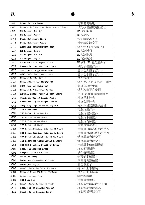
5253
REAGENT REFRIGERATOR TEMPERATURE HIGH
试剂冰箱温度过高
5301
PANIC VALUE A, B, C, D
达到病理值
5302
HbA1cPRETREATMENT CHECK RANGE ERROR
糖化预处理范围检查错误
5303
HbA1c% CALCULATION FAILED
5110
ILLEGAL REAGENT POSITION
不规则的试剂位置
5111
REAGENT EXPIRED
试剂失效
5112
DIFFERENTLOTNO. REAGENT FOUND
5114
REAGENT TYPE CONVERTED
试剂类型改变
5115
BOTTLE TYPE CONVERTED
瓶子类型改变
样本注射器灌注未完成
3250
ISE Cover Open
电解质盖打开
3251
ISE Buffer Solution Short
电解质缓冲液少
3252
ISE MID Solution Short
电解质中值液少
3253
ISE REF Solution Short
电解质内标液少
3254
ISE Detergent Short
5751
PRINTER NOT SELECTED
未选择打印机
5752
PRINTER NOT AVAILABLE
打印机不可用
5753
PART OF DATA IS NOT OUTPUT YET
部分数据暂未输出
6010
2000KN全自动压力机期间核查

2000KN全自动压力试验机期间核查作业指导书编制:李涛涛批准:李海燕宁夏宏禹水利水电建设工程质量检测有限公司批准日期:2017-03-10 实施日期:2017-03-102000KN全自动压力机期间核查1.核查对象2000kN压力试验机2.核查器具2000kN标准测力仪3.环境条件室内温度10℃~35℃;湿度不大于80%RH.4.核查依据《拉力、压力和万能试验机》JJG139-2014鉴定规程。
5.技术要求最大允许值(%)6.核查方法(1)核查前,标准测力仪应放置足够的时间使其达到稳定的温度;(2)利用标准测力仪用递增方式对2000kN压力试验机量程200kN、400kN、800kN、1200kN、1600kN、1800kN六个测量点进行测量,每个测量点进行3次测量。
7.数据处理1、利用每个测量点三次测量的平均值与压力试验机示值计算该测量点的示值相对误差;2、利用每个测量点三次测量中最大测量值、最小测量值以及三次测量平均值计算该点示值重复性相对误差;3、判断示值相对误差、示值重复性相对误差是否满足技术要求。
8.结果处理若示值相对误差、示值重复性相对误差均满足技术要求,则判定该仪器此次核查合格,可以继续使用;若不满足要求,应停止使用并进行标定,标定结束后对仪器重新核查,合格方可使用。
9.核查周期一般在仪器的检定周期内进行一次核查,当使用频率大时应增加核查次数。
10.应具备的相关文件及记录1)期间检查方案2)检查原始记录2000kN全自动压力机期间核查方案根据仪器设备期间核查年度计划的安排制定此期间核查方案。
1.核查人员及成员:组长:技术负责人李海燕组员:李海燕、沈飞、李涛涛记录:李涛涛计算:李涛涛2.核查仪器情况说明管理编号:077名称代号:2000kN全自动压力试验机工作使用年限:2017年至今。
3.执行文件:EJ2Y-CX-5-13《仪器设备与标准物质期间核查程序》2000KN全自动压力试验机仪器使用说明书及期间核查操作方法4.该仪器最近一次检定时间为:2017年3月10日编制:李涛涛批准:李海燕附件材料:期间核查仪器设备操作记录及不确定度报告2000KN全自动压力试验机期间核查结果的不确定报告一、概述1.环境条件:温度21℃2.试验仪器:标准测力仪,型号: ,编号: ,测量范围0-2000kN。
MSE-2000R检漏仪中文说明书

请由二人从前后分 别用手抓住“※”标记的
位置进行搬运。
搬运时,请勿将手置于前盖的下方。
[ 注 意]
请勿在主机上方放置重物或坐于主机上方 如在主机上方放置重物或坐于主机上方,会导致主机罩盖变形•破损,影 响安全性,敬请注意。
-4-
[ 警 告]
MSE-2000R
保养•检查本装置时
本装置内部存在高压电(450 V)部分。为防止触电,在保养•检查本装置时, 请务必先关闭[POWER]开关并拔掉电源线,然后再卸下顶盖。
2)本说明书内容如有改动恕不另行通知。 3)本说明书内容力求准确,如有错误或遗漏敬请谅解。 4)本产品和维修零部件的供应期限为制造结束后 10 年。超出此供应期限之后,可
能无法供应维修零部件,敬请谅解。但是,非本公司原装的零部件,其供应期限 由该零部件的生产厂商规定。
-3-
MSE-2000R
[ 注 意]
9.输入输出系统 ..................................................................................................................... 47 9.1.记录仪输出 .............................................................................................................. 47 9.2.打印机(选购件) .................................................................................................. 49 9.3.RS-232C ................................................................................................................... 50 9.4.EXT-UNIT................................................................................................................ 55
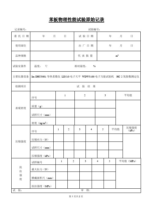
实验室用苯板氧指数原始记录
试样尺寸(mm)
密度(kg/m3)
压缩强度
序号
1
2
3
4
5
平均值
压缩强度(kPa)
压缩应力(N)
试样尺寸(mm)
压缩强度(kPa)
抗
拉
强
度
试样编号
1
2
3
4
5
平均值(MPa)
最大拉力(N)
横截面积尺(mm)
抗拉强度(MPa)
试验:审核:
第
苯板物理性能试验原始记录
记录编号:试验编号:
氧指数
初始氧浓度Ψo
NT系列的测定
NT系列的测定
氧浓度ΨF
氧浓度(%)
燃烧时间(s)
燃烧长度(mm)
反应
试样尺寸(mm)
初始氧浓度Ψo(%)
修正系数K
步长d
氧指数OI(%)
导
热
系
数
试样面编号
1
2
温度(℃)
试样厚度(cm)
传热面积(m2)
主加热器电压(V))
主加热器电流
(I)
导热系数(W/m·K)
执行标准
GB/T10801.1-2002 GB/T6343-2009
GB/T10294-2008 JG149-2003
GB/T2406.2-2009
备注
评语
2000型压力试验机操作规程
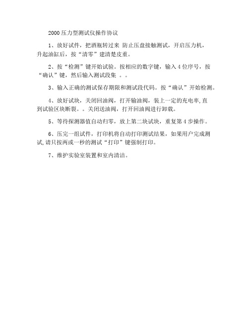
2000压力型测试仪操作协议
1、放好试件,把酒瓶转过来防止压盘接触测试,开启压力机,
升起油缸后,按“清零”建清楚皮重。
2、按“检测”键开始试验。
按相应的数字键,输入4位序号,按“确认”键,然后输入测试段集。
3、输入正确的测试保存期限和测试段代码。
按“确认”开始检测。
4、放好试块,关闭回油阀,打开输油阀,装上一定的充电率,直
到试验区块断裂。
关闭送油阀,打开回油阀进行卸载。
5、等待探测器值自动归零,放上第二块试块,重复第4步操作。
6、压完一组试件,打印机将自动打印测试结果,如果用户完成测试,请只按两或一秒的测试“打印”键强制打印。
7、维护实验室装置和室内清洁。
002 HMC-2000 成品检验标准书

文件名称 机种名称鸿利高电 鸿利高电器文件编号 页 码抽样计划 允收水准检验标准书 HMC-2000 系列 GS HMC-2000( W /T/TW/TIM/T-TIM/W-TIM/TW-TIM) ( ) WI-QC-002 第1页 共6页 A /0 版 本根据 MIL-STD-105E Ⅱ、S-1 、S-2 ; AQL: CRITICAL:0 MAJOR:1.0 MINOR:2.5CR--用户使用时会造成人身伤害或财产损失的缺陷 缺陷描述 MAJ--能造成操作不顺、或功能不良影响产品销售的缺陷 MIN--不影响产品的正常使用,但可能会引起客户的抱怨(主要为外观)的缺陷HMC-20001) 2) 3) 4) 有两位船形开关 不带电机 不带定时 不带挂墙HMC-2000W1) 2) 3) 4) 有两位船形开关 带挂墙 不带电机 不带定时HMC-2000T 产品 图片 型号 区分1) 2) 3) 4) 三位船形开关 带电机 不带定时 不带挂墙HMC-2000TW1) 2) 3) 4) 三位船形开关 带挂墙 带电机 不带定时HMC-2000-TIM1) 两位船形开关 ) 2) 带定时 ) 2) 不带电机 ) 3) 不带挂墙 )HMC-2000W-TIM1) ) 2) ) 3) ) 4) ) 两位船形开关 带挂墙 带定时 不带电机HMC-2000T-TIM1) 三位船形开关 ) 2) 带电机 ) 3) 带定时 ) 4) 不带挂墙 )HMC-2000TW-TIM1) ) 2) ) 3) ) 4) ) 三位船形开关 带电机 带定时 带挂墙测试方法/ 工具 缺 陷 判 别 CrMaj Min一、包装检查: 包装检查:1、外箱检验:(II)(PQC、QA 适用 、 适用)a. 外箱的纸质要符合制造命令单、套料表的要求.否则 b. 彩盒、卡通箱等不可有破损,特别是客户品牌、条形码不可刮花. c. 外箱的封箱胶纸要平整、 美观、 不可有胶纸飘起,明显起趋或封不到位. d. 外箱的各种贴纸要平整,不可有气泡,歪斜、卷角等现象. 2.包装资料核对:目视 目视 目视 目视x x x x文件名称 机种名称鸿利高电 鸿利高电器文件编号 页 码检验标准书 HMC-2000 系列 GS HMC-2000( W /T/TW/TIM/T-TIM/W-TIM/TW-TIM) ( ) WI-QC-002 第2页 共6页 A /0 版 本a. 说明书、保修卡、机身贴、黄卡、警告语、等要符合包装资料,印刷 内容要清晰,不可有漏字、多字、重影等现象.且各印刷的功率、电流、 电压、型号等内容要一致.否则 b. 机身贴内容一定要与外箱唛头相一致,认证符号的尺寸要符合要求.否 c. 所用的胶袋要符合规格(厚度、警告语、 、印刷颜色及透明度). d. 所有胶袋要有回收标、环保标、透气孔,(胶袋口大于 7 英寸要有警告 语与透气孔)否则 e. 外箱唛头、图案要正确、认证符号的尺寸要符合要求. f. 条形码模糊,错误或通不过扫描 B 級以上 3.配件检验: a. 说明书及保修卡等附件漏装或用错 b. c. 相关机脚颜色不可错误及漏放机脚 所配螺丝规格正确, (字槽大扁自攻(尖头)ST3.5 x 12-C-H)4 颗, 无漏装少装,否则目视x x x x x x目视 目视 目视 目视 条码仪目视 目视 目视 目视x x x xd. 相关挂墙配件是否规格错误,漏装。
2000小时盐雾实验报告
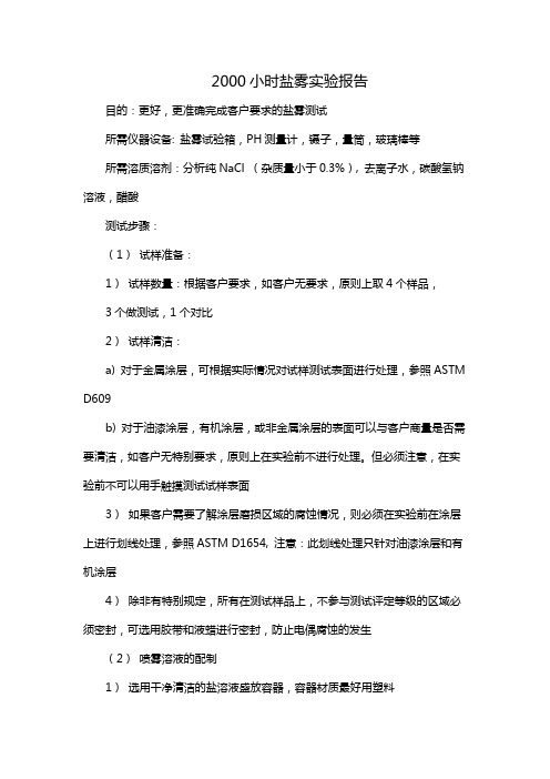
2000小时盐雾实验报告目的:更好,更准确完成客户要求的盐雾测试所需仪器设备: 盐雾试验箱,PH测量计,镊子,量筒,玻璃棒等所需溶质溶剂:分析纯NaCl (杂质量小于0.3%), 去离子水,碳酸氢钠溶液,醋酸测试步骤:(1)试样准备:1)试样数量:根据客户要求,如客户无要求,原则上取4个样品,3个做测试,1个对比2)试样清洁:a) 对于金属涂层,可根据实际情况对试样测试表面进行处理,参照ASTM D609b) 对于油漆涂层,有机涂层,或非金属涂层的表面可以与客户商量是否需要清洁,如客户无特别要求,原则上在实验前不进行处理。
但必须注意,在实验前不可以用手触摸测试试样表面3)如果客户需要了解涂层磨损区域的腐蚀情况,则必须在实验前在涂层上进行划线处理,参照ASTM D1654, 注意:此划线处理只针对油漆涂层和有机涂层4)除非有特别规定,所有在测试样品上,不参与测试评定等级的区域必须密封,可选用胶带和液蜡进行密封,防止电偶腐蚀的发生(2)喷雾溶液的配制1)选用干净清洁的盐溶液盛放容器,容器材质最好用塑料2)用1000 ml的量筒将已准备好的,并符合ASTMD1193规定的去离子水盛入盐溶液盛放容器作为溶剂,记下盛入去离子水的质量3)根据公式:溶液浓度=溶质质量/ (溶质质量+溶剂质量)计算需用NaCl的质量,用烧杯,电子天平进行称量,并记录称量次数及每次称量的质量,注意当NaCl加入2)步去离子水中的质量损失,尽可能降到最低4)在NaCl加入2)步去离子水后,用玻璃棒进行匀速搅拌,加速NaCl 水中的溶解5)当NaCl溶解到一定程度时,(几乎看不到在容器底部有未溶解的NaCl)用PH值测量计调节溶液的PH值,a) 将PH值测量计从盒内取出,把探头连接线和主机连接b) 取下为保护探头而固定在探头上的等离子水瓶,用蒸馏水清洗探头,并用吸水纸轻轻擦拭,确保探头不被损坏c) 打开主机开关,将擦干后的探头放入标准比对试剂中进行仪器校准,并确认仪器所测量的PH值在正常范围内,可以正常使用d) 将探头伸进已配好的溶盐液中,在玻璃棒不停地搅拌下进行PH值的调整,中性盐雾测试要求PH值:6.5 ~7.2(35+1.1-1.7°C), 酸性盐雾测试要求PH值:3.1 ~ 3.3(35+1.1-1.7°C),可以用碳酸氢钠溶液和醋酸溶液进行PH值的调整,注意:标准规定的PH值是在35°C左右下的要求,所以在室温下调节的PH值应该比标准值略低e) 在PH值调整完毕,符合标准规定后,关闭主机,从盐溶液盛放容器中取出探头,用蒸馏水洗,并用吸水纸轻轻擦拭,将探头重新固定在等离子水瓶中f) 分离探头与主机的连接线,放入盒中6)此时将盐溶液盛放容器的盖子盖紧,并用力摇晃1分钟左右,使溶液更加均匀7)摇匀后将容器的接口与盐雾实验箱的盐溶液进口连接,或将溶液倒入盛药箱(3)喷雾实验过程中1)开启盐雾箱,根据实验要求设置箱内温度,饱和塔温度,喷雾压力(一般上述参数均已设定好了,在无特殊要求下,参数不做改变)注意:在每次开启盐雾箱前,必须加入冷凝水(蒸馏水或去离子水),以保证饱和塔正常工作,冷凝水一定要在关机情况下操作2)要将测试样品放如盐雾箱,待16小时后再放入3)16 小时后,放入测试样品,注意放置测试样品的位置,样品之间不能互相接触,要与竖直方向成15 到30 度的夹角,必要时,可用细线绑。
东芝2000FR参数设置

东芝2000FR参数设置一、设定试剂1、点【Reagent】,点上方的【R1】,选择任意空格双击,Name后输入试剂名称,选择Type为R1,选择Bottle Size瓶子的尺寸,输入Alert V olume%按瓶子的10%为警戒体积(或者输入Alert Numbers警戒个数),点OK。
2、R2输入方式同上。
二、设定定标和质控1、设置定标:点【C/C】,点上方的【Calibrator Set】标签,在空白区域双击,在弹出的画面中设置,Calibrator setname后设置名称,如果使用条码就在ID后输入ID号(最少6个字符),如果不使用条码,就只需在Rack No 后输入QC杯架号,在Calibrator set pattern后选择合适的校准物使用方式,在Level后输入校准物的数量,点【Apply】保存。
如果使用条码,在界面中会有【Print Label】按钮,点击它打印条码。
空白用水Water(仪器已设有此名称)的设置也是同样的。
2、设置质控:点【C/C】,在出现的界面中选择【Control Sample】标签,不使用条码只用设名称,使用条码方法同定标设置。
三、参数设置1、点【Assay】,点任意空位,点OK。
2、点【Outline】,Assay ID输入项目通道号,Assay Code输入项目名称,Order ID输入加样顺序编号(建议OrderID与Assay ID一致)。
3、点【Base】,Reaction Mode选择反应模式,Main/Sub Wave Length选择主副波长,Main输入主要读点时间,(如为两点终点法,则勾选Self Blank Test,Blank Read Timeing 输入14-16), Standard后输入样品量,试剂放在A-C的试剂架中选择Outside(Rack A-C),试剂放在D试剂架选择Intside(Rack D),Reagent1/Reagent2后选择试剂并输入试剂量,Decimal Places输入小数位数。
固定资产控制程序(中英文)

固定资产管理规定1. 目的:确定本公司固定资产定义及分类,确保公司所有固定资产之申购、运用、处理得到有效控制。
2. 范围:本程序适用于本公司固定资产的控制。
3. 定义:固定资产:单位采购价值在人民币两千元以上,使用期限超过一年的为生产商品、提供劳务、出租或经营管理而持有的机器、机械、运输工具以及其它设备、工具、器具等物品;我公司对单位价值低于2000元的空调、电视、电脑显示器及打印机也作为固定资产。
ESR:工程服务申请单4. 职责权限:4.1 使用部门:参与固定资产的验收、维护、保养、保管、报废、停用的评估和固定资产的申请。
4.2 QA:负责对办公电脑及与生产有关的固定资产的申购、验收、停用、报废、调拨的评估。
4.3 HR&A:负责厂房设施及其他非生产性固定资产的申购、验收、停用、报废、调拨的评估。
4.4 PUR:负责固定资产的采购和请款,采购定单上要清楚标示固定资产采购以区分其他采购订单,付款申请需附固定资产验收单。
4.5 FIN:根据QA或HR&A提供的固定资产验收单编列固定资产编号,列账管理,編制固定资产清单。
统筹部门需提供使用部门保管人签名的保管人清单正本,向财务部申請固定资产发放标签並配合标签的粘贴。
FIN负责检查和监督标签的粘贴和保管人的签名确认;采购申请付款时负责审核付款条件和附件,对公司固定资产进行财务管理,定期组织固定资产盘点。
5. 程序:5.1 固定资产的配置5.1.1 固定资产的购买申请需使用部门最高负责人批准。
5.1.2 公司可自行设计制作的固定资产,由QA或HR&A部安排自制。
5.1.3外购的固定资产,经PUR选择供应商并进行报价,经使用部门和FIN最高负责人批准后方可采购。
5.2 安装5.2.1生产性固定资产到达公司后,由QA按说明书及相关规定进行安装、调试。
5.2.2非生产性固定资产由HR&A按行业标准进行安装,调试.5.3 验收QA和HR&A按设备说明书,合同规定的相关性能要求对固定资产进行测试,合格后需填『验收报告』,验收报告原件交财务请款,相关部门复印留底。
北美工业2000磅容量胶带拉力机产品说明书
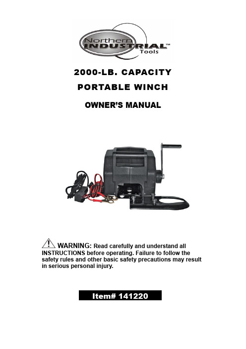
2000-LB. CAPACITYPORTABLE WINCHOWNER’S MANUALWARNING: Read carefully and understand all INSTRUCTIONS before operating. Failure to follow the safety rules and other basic safety precautions may result in serious personal injury.Thank you very much for choosing a Northern Industrial. Product! For future reference, please complete the owner’s record below:Model: _______________ Purchase Date: _______________Save the receipt, warranty and these instructions. It is important that you read the entire manual to become familiar with this product before you begin using it.This winch is designed for certain applications only. The distributor cannot be responsible for issues arising from modification. We strongly recommend this winch is not modified and/or used for any application other than that for which it was designed. If you have any questions relative to a particular application, DO NOT use the winch until you have first contacted the distributor to determine if it can or should be performed on the product.For technical questions please call 1-800-222-5381.INTENDED USE1. Convenient, portable power for pulling boats, stuck vehicles and other heavy items.2. Powerful 2000-lb. pulling power.3. 12 Volt powered for convenient use without extension cords or small gas engines.4. Portable, with built-in carrying handle and quick-attach mounting plate.TECHNICAL SPECIFICATIONSItem DescriptionCapacity: 6000 Lbs. Rolling.5000 Lbs. Marine2000 Lbs. Pulling CapacityMax. Boat Size: 18 Feet (5.5m)Max. Boat Weight: 5000 Lbs. (2268 kg)Line Speed: 6 Feet/Minute with LoadCable Length: 30 Feet (9m)Hook Size: 3/4in. Opening x 3-3/4in.LPower Supply: 12 VoltsPower Cord: 6 Foot (2m) Negative Lead14 Foot 9 Inches (4.25m, 230mm) Positive LeadRemote Switch: 9 Feet 9 Inches (2.75m, 230mm)Mounting Plate: 8-3/4in. x 4-15/16in. x 3/16in.Overall Dimensions: 9-1/2in. x 7-1/2in. x 10in.INCLUDED ACCESSORIES:1. Power lead, fitted with water resistant plug and circuit breaker.2. Remote switch with water resistant plug, for safe operation.3. 30-ft. aircraft cable with attached hook.4. Mounting bracket for trailer hitch.5. Emergency crank handle and adjustable clutch.PULLING CAPACITY1. This winch has a pulling capacity of 2000 lbs. Applying this capacity to practical applications, you can use this winch to move the following:a. Move a load from a dead stop of up to 2000 lbs. on level ground.b. Move a watercraft of up to 4800 lbs.c. Maintain movement of a wheeled vehicle of up to 6000 lbs.2. Pulling Capacity is reduced as incline increases. For example, rolling capacity is reduced from 6000 lbs. on flat ground to 1100 lbs. on a 45°incline.Refer to the following chart for estimated pulling capacity (rolling weight) on various inclines.Maximum (Rolling) Weight Capacities on an InclineGENERAL SAFETY RULESWARNING: Read and understand all instructions. Failure to follow all instructions listed below may result in serious injury. Do not exceed indicated weight capacity.WARNING:The warnings, cautions, and instructions discussed in this instruction manual cannot cover all possible conditions or situations that could occur. It must be understood by the operator that common sense and caution are factors which cannot be built into this product, but must be supplied by the operator.SAVE THESE INSTRUCTIONSYou will need this manual for the safety warnings and cautions, assembly instructions, operating procedures, maintenance procedures, trouble shooting, parts list, and diagram. Keep your invoice with this manual. Write the invoice number on the inside of the front cover. Keep both this manual and your invoice in a safe, dry place for future reference.WARNING: When using powered equipment, basic safety precautions should always followed to reduce the risk of personal injury and hazards.WORK AREAKeep work area clean, free of clutter and well lit.Cluttered and dark work areas can cause accidents.Do not use your winch where there is a risk of causing a fire or an explosion; e.g. in the presence of flammable liquids, gasses, or dust. Electrically powered tools can create sparks, which may ignite the dust or fumes.Keep children and bystanders away while operating a winch. Distractions can cause you to lose control, so visitors should remain at a safe distance from the work area.Be aware of all power lines, electrical circuits, water pipes and other mechanical hazards in your work area, particularly those hazards below the work surface hidden from the operator’s view that may be unintentionally contacted and may cause personal harm or property damage.Be alert of your surroundings. Using winches in confined work areas may put you dangerously close to cutting tools and rotating parts.PERSONAL SAFETYStay alert, watch what you are doing and use common sense when operating a winch. Do not use a winch while you are tired or under the influence of drugs, alcohol or medication. A moment of inattention while operating a winch may result in serious personal injury.Dress properly. Do not wear loose clothing, dangling objects, or jewelry. Keep your hair, clothing and gloves away from moving parts. Loose clothes, jewelry or long hair can be caught in moving parts. Air vents often cover moving parts and should be avoided.Use safety apparel and equipment. Use safety goggles or safety glasses with side shields which comply with current national standards, or when needed, a face shield. Wear heavy leather gloves when handling a wire rope. Use as dust mask in dusty work conditions. This applies to all persons in the work area. Also use non-skid safety shoes, hardhat, gloves, dust collectionsystems, and hearing protection when appropriate.Avoid accidental starting. Ensure the switch is in the off position before connecting winch into power supply. In the event of a power failure, while a winch is being used, turn the switch off to prevent surprise starting when power is restored.Always stand clear of wire rope and load during operation, and keep bystanders away as well.Do not try to guide the cableAlways be certain the anchor you select will withstand the load, and the strap or chain will not slip.Never use as an overhead hoist, or to suspend a load.Never use to lift or move persons.Never exceed the winch or wire rope rated capacity.Never apply load to hook tip or latch. Apply load to only the center of the hook.Never use a hook whose throat opening has increased, or whose tip is bent or twisted.Never touch wire rope or hook while in tension or under load.Never hook wire rope back onto itself.Do not apply a load to the winch when the cable is fully extended. The cable fastener is not capable of holding the rated capacity.Do not overreach. Keep proper footing and balance at all times.Remove adjusting keys or wrenches before connecting to the power supply or turning on the winch. A wrench or key that is left attached to a rotating part of the winch may result in personal injury.MAINTENANCEMaintain your winch. It is recommended that the general condition of your winch be examined before it is used. Keep your winch in good repair by adopting a program of conscientious repair and maintenance in accordance with the recommended procedures found in this manual. If any abnormal vibrations or noise occurs, stop using the winch immediately and have the problem corrected before further use. Check for damage to the cable, including bending, fraying or kinking.Have necessary repairs made by qualified service personnel.e only soap and a damp cloth to clean your winch. Many household cleaners are harmful to plastics and other insulation. Never let liquid get inside a winch.Replacement parts and accessories. When servicing, use only identical replacement parts.Use of any other parts will void the warranty. Only use accessories intended for use with this winch.!Maintain winch with care Follow instructions for lubricating and changing accessories. Inspect power cord periodically and, if damaged, have it repaired by an authorized technician. Inspect all moving parts and mounting bolts prior to use. Control handle and power switch must be kept clean, dry and free from oil and grease at all times.!Lubricate the cable occasionally with light oil.!Grease the gears every 6 months. To do this, remove the clutch knob and separate the left and right housing. Use any good quality waterproof grease.AssemblyWiring your Electric WinchYour Winch may be used with temporary or permanent wiringNOTE: Mount the winch prior to completing the wiring.Temporary Wiring1. Lift the rubber seal and plug the POWER CABLE (#39) into the PLUG (#36) on the right side ofthe winch body. This plug is labeled “power.” Route the Power Cable from the winch to your battery, being careful to avoid tangling it in moving equipment, or causing a tripping hazard.2. Connect the Black Clamp Handle of the POWER CABLE (#39) to the frame of your vehicle,establishing a ground connection. Connect the Red Clamp Handle to the Positive (+/Red) terminal of your battery. Note:Be sure you are using a 12V automotive battery or equivalent, in good condition.3. Lift the rubber seal on the left side of winch body. Taking the Remote Control Unit, insert theSocket at the end of the cord into the Plug on the left side of the winch body labeled “Remote Control.”4. Set the remote control aside in a safe place until ready for use.Permanent wiring1. Attach the OVER-CURRENT PROTECTOR (#31) to the Positive (+/Red) terminal of your battery,using the battery terminal clamp bolt.2. Plan a route for the wiring from the point of the vehicle where the winch will be mounted or usedto the battery. This route must be secure, out of the way of moving parts, road debris, or any possibility of being damaged by operation or maintenance of the vehicle. For example, you may wish to route the wires under the vehicle, attaching it to the frame using suitable fasteners. Donot attach the wires to the exhaust system, drive shaft, emergency brake cable, fuel line, or any other components which may create damage to the wiring through heat or motion, or create a fire hazard.3. If you drill through the bumper or any part of the body to route the wires, be sure to install arubber grommet in the hole to prevent fraying of the wires at that point.4. Route the POWER CABLE (#39) from the point the winch will be used to the battery. Followingthe precautions discussed above.5. Remove the Red Clamp handle, and attach the red wire to the OVER-CURRENT PROTECTOR(#31) which is mounted onto the Positive (+/ Red ) terminal of your battery.6. Remove the Black Clamp handle, and attach the black wire to the frame of your vehicle, creatinga secure electrical ground.WARNING:Always connect Red to Red (Positive to Positive) and Black to the vehicle’s frame, making a ground connection, when using battery power from your vehicle.Never continue use of your winch or other accessory until the battery is completely run down.This can permanently damage your battery!You may wish to keep your engine running while using this winch, to continually recharge the battery. However, exercise extreme caution when working around a running vehicle. (See USING YOUR WINCH on page 7 of this manual.)Do not use a dirty, corroded or leaking battery. You may suffer injury from acid burns.Always wear ANSI-approved safety glasses when working around or with a battery.OPERATIONMOUNTING YOUR WINCHYour winch is designed to be mounted temporarily, using the Trailer Hitch Mounting Bracket. However, you may also mount your winch permanently.Permanent Mounting1. Select a mounting site on the bumper of your vehicle, truck bed, boat trailer, or other suitablelocation. NOTE: This winch can generate 2000 lbs. pulling force. Be sure the location you select can withstand this much force. You may need to use steel reinforcement plates, or weld on additional bracing, depending on the desired mounting location.2. Align the winch with the desired location, and mark for drilling the locations of the 4 holes on thebase of the winch.3. Drill these locations on your vehicle.4. Using hardened steel bolts at least 3/8in. in diameter, install your winch to the location.Temporary Mounting1. Attach the three Plate Stud Bolts to the Adapter Plate, as shown, (see Diagram on page 9)usingthe supplied Nuts. Tighten securely.2. Index the heads of the Plate Studs into the keyhole slots on the back of the winch.3. Attach the Winch/Adapter Plate assembly to your trailer hitch, by inserting the trailer hitch ballthrough the shaped hole in the Adapter Plate.WARNING!Keep hands, clothing, hair, and jewelry clear of the drum area and cable when winching.Never use the winch if the cable is frayed, kinked or damaged.Never allow anyone to stand near the cable or in line with the cable behind the winch while it is under power. If the cable should slip or break, it can suddenly whip back toward the winch, causing a hazard for anyone in the area. Always stand well to the side while winching.USING YOUR WINCHCAUTION:Never touch wire rope or hook while operating the winch, or while the rope is under a load.1. Put your vehicle in Neutral. (Never winch with your vehicle in Gear or in Park, since this coulddamage your vehicle’s transmission.) PUT YOUR EMERGENCY BRAKE ON. BLOCK THE WHEELS FROM ROLLING, USING SUITABLE CHOCKS. FAILURE TO FOLLOW THESE INSTRUCTIONS CAN CAUSE YOUR VEHICLE TO ROLL WHILE WINCHING, CREATING AN EXTREMELY DANGEROUS SITUATION!!2. To pull out the cable, turn the CLUTCH KNOB (#19) counterclockwise to loosen it, and then pullout the cable you need. ALWAYS LEAVE AT LEAST THREE TURNS OF CABLE ON THE SPOOL TO PREVENT PULLING THE CABLE OUT OF THE WINCH!3. Hook onto the object using a pulling point, tow strap or chain. Never wrap the cable around theobject and hook onto the cable itself. This can cause damage to the object being pulled, and kink or fray the cable.4. Re-tighten the clutch knob.5. Stand clear, and when it is safe to do so, use the power switch in the remote control to retract thecable, and winch the item as desired.6. After moving the item, secure it. Do not rely on the winch to hold an item for an extended periodof time.SPECIAL WARNINGS WHEN USING THIS ELECTRIC WINCHUsing this powerful tool may create special hazards.Take particular care to safeguard yourself and those around you.The Cable.Be sure the cable is in good condition, and is attached properly.Do not use the winch if the cable is frayed.Do not replace the cable with a cable of lesser strength.The Battery.Be sure the battery is in good condition. Avoid contact with battery acid or other contaminants.Always wear ANSI-approved eye protection when working around a battery.Have the engine running when using the winch, to avoid running the battery down.Stand Back.Stay out of the direct line that the cable is pulling. If the cable slips or breaks, it will “whiplash” along this line.Do not stand between the winch and the load when operating.Keep hands, clothing, hair and jewelry clear of the winch while in use.Use a spotter to assist you in assuring that it is safe to operate the winch. Make sure this person is out of the way of the vehicle and the cable before activating the winch.Power Limits.Do not attempt to exceed the pulling limits of this winch.Never use the hand crank to “assist” the winch. This will damage the winch and may cause personal injury.USING THE EMERGENCY HAND CRANKWarning:Do not use the crank to assist an operating winch. This will damage the winch and may cause personal injury.1. Turn the clutch knob clockwise until hand tight. Do not force it or over tighten.2. Place the end of the hand crank over the flattened end of threaded shaft on the left side of thewinch.3. Rotate the hand crank clockwise to tighten the cable. Continue to turn until the cable has beencompletely retracted.DIAGRAM & PARTS LISTPart# Description Part#Description1 Electrical wire 34 Spring2 Lock washer 35 Left shell3 Nut 36 Nut4 Adapter plate 37 Lock spring5 Screw 38 Plate6 Remote control housing39 Cord protector7 Self-tapping screw 40 Screw8 Control wire 41 Switch9 Nut 42 Relay10 Hand crank 43 Screw11 Spring lock 44 Motor12 Nut 45 Fast plate13 Lock washer 46 Screw14 Gear 47 Fast plate15 Clutch knob 48 Bearing16 Friction plate 49 Nut17 Steel plate 50 Shaft18 Steel plate 51 Gear19 Gear assembly 52 Plate20 Friction plate 53 Lock washer21 Screw 54 Lock spring22 Lock washer 55 Nut23 Lock washer 56 Shaft24 Frame 57 Lock washer25 Gear 58 Gear26 Lock spring 59 Lock washer27 Screw 60 Nut28 Lock washer 61 Split-pin29 Screw 62 Jack30 Lock washer 63 Cover31 Claw lock 64 Right shell32 Shaft lock 65 Steel cable and hook33 Shaft lockFor replacement parts and technical questions, please call 1-800-222-5381.WARRANTYOne-Year Limited WarrantyDistributed byNorthern Tool + Equipment Co., Inc.Burnsville, MN 55337-0499Made in China。
德普2000化学发光仪操作维护程序

《文件已阅声明表》《Procedure circulation form》文件名称:德普2000化学发光仪操作维护程序表号:KM-MP03.02.02《文件修改记录页》《Procedure amendment form》表号:KM-MP03.02.03《文件信息表》《Procedure information form》表号:KM-MP03•02•04德普2000化学发光仪操作维护程序(DPC Immulite 2000 operation and maintenance procedure) 1. 目的(Purpose):对化学发光室德普2000化学发光仪的操作和维护过程进行控制,以确保仪器满足检测要求。
2. 范围(Scope):德普2000化学发光仪。
3. 职责(Responsibility):化学发光室授权技术人员(Technologist)负责德普2000化学发光仪的日常操作和维护。
4. 操作规程(Operation procedure):4.1仪器准备(Equipment preparation)●打开IMMULITE 2000显示器开关,打开IMMULITE 2000运行程序,点击RUN IMMULITE 2000运行。
●打开打印机。
●检查去离子水、底物、洗液、试剂杯是否够用,液体和固体垃圾是否需要清除。
●排除气泡后进行探针清洗工作。
●运行LMMULITE 2000系统程序(点击RUN按扭)。
4.2操作步骤●打开试剂槽盖,点击一个空的试剂槽使其转到槽口,放入试剂楔。
●打开包被珠槽盖,点击一个空的包被珠槽使其转到槽口,放入包被珠。
●将加有样本的试管放入样品架中,并将实验号与对应的样品架位置记录下来,将样品架推入样品槽中,点击RUN。
●经仪器扫描样品架后,在WORKLIST菜单下PATIENT栏中选择Assign Tube Position ,指定样本位置;在Accession一栏中填入实验号;在TESTS中指定项目。
IEC 60950 EN60950(2000版)测试简介

IEC 60950/EN60950(2000版)测试简介机构部分测试(PHYSICAL TESTS)1*、固定力测试(STEADY FORCE TEST)(CLAUSE 4.2.1, 4.2.2,4.2.3,4.2.4)4.2.1 General(一般要求)外壳应具有足的机械强度。
若外壳提供了足够的机械防护,对于为满足4.6.2而提供的内部挡板、罩或类似物,则不要求进行机械强度实验。
对于所有的设备要求通过4.2.2,4.2.3,4.2.4,4.2.5的测试,对于手持设备还要求通过4.2.6的跌落实验。
4.2.2 Steady force test , 10N(固定力测试,10牛顿)Components and parts, other than parts serving as an ENCLOSURE (see 4.2.3 and 4.2.4),aresubjected to a steady force of 10N+/-1N。
元器件在承受10N的外加力时,不能影响到安全。
4.2.3 Steady force test , 30N(固定力测试,30牛顿)Parts of an ENCLOSURE located in an OPERATOR ACCESS AREA, which are protected by acover or door meeting the requirements of 4.2.4, are subjected to a steady of 30N+/-3N for aperiod of 5s,applied by means of a straight unjointed version of the test finger, of figure 2A(see2.1.1.1), to the part on or within the equipment.安装在操作人员接触区内的并由满足4.2.4要求的罩或门来保护的外壳零部件应承受30N+/-3N的恒定作用力持续5s。
LR2000千米兆抗阻性测试仪说明书

• Winding Resistance of Motors, Transformers, Solenoids, and Ballasts
• Conductivity Evaluation in Product Design
Test Signal: Besides the standard DC test signal, the LR2000 provides a signal reversal mode for eliminating thermal EMF's, and pulsed current mode for minimizing errors caused by device heating.
Zeroing: An automatic zeroing functions reduces the effects of lead resistance through the front panel 4-terminal Kelvin connection.
Interfaces: For remote control, or adaptation to a production type environment, the LR2000 includes an RS-232 interface. An optional IEEE-488 and Handler interface is also available.
±(0.1% of rdg + .006m ) ±(0.05% of rdg + .06m ) ±(0.05% of rdg + .6m ) ±(0.05% of rdg + 6m ) ±(0.05% of rdg + 40m ) ±(0.05% of rdg + .2 ) ±(0.1% of rdg + 2 ) ±(0.2% of rdg + 20 ) ±(0.4% of rdg + 200 )
Horiba LAQUA 2000系列表面水质仪说明书
Conductivity ResistivitySalinitypH2000 Series Benchtop Water Quality MetersWA R R A N TYWA RR AN TY3 YEAR2Adjustable, Integrated Electrode StandHolds up to 2 electrodes and can be positioned on either side of the meterReady to go out of the boxMeter kits come with electrodes and calibration solutions5” Digital Backlit DisplayShows all important readings and indicators for every measurementElectrode StatusReveals electrode condition based on calibration dataSmiley and beep soundIndicate reading stability inmeasurement and calibration modes2000 Series Benchtop Water Quality MetersUniversal Power AdaptorMulti-voltage 100~240V with 6 plugs (US, UK, EU, ANZ, Korea, China)Sleek DesignClean and elegant body with rounded edgesSmaller FootprintPerfect for large and even small-scale labs as meter occupies minimal spaceAuto Cal Standards Icon lights up after calibration making standard solutions used viewable at a glance Real Time ClockKeeps precise time and dateand facilitates functions that aretime-dependentLarge InternalMemoryAccepts up to 2000 data setsAuto Data Log Captures and stores data into memory based on specified time intervalAdjustable Shut-Off TimeSwitches the meter off at idle (up to 30 minutes)TemperatureCalibrationCAL Temp Mode allowstemperature calibrationPassword ProtectedA 4-digit password secures the metersetup mode from unauthorized accessSoftware UpgradeLatest software version can beloaded into the meter when available2000 Series Benchtop Water Quality MetersData AcquisitionSoftware ConnectivityData can be transferred to computerand exported to CSV/Excel/PDFvia USB cable and complimentaryDAS20 software45Temperature CompensationTemperature in °C or °F is either automatically detected when temperature sensor is connected (ATC mode) or manually entered by the user (MTC mode)Auto Stable Auto Hold Real TimeATC modeMTC modeData Printing CapabilityData with date and time stamp can be printed for GLP/GMP complianceAudible FeedbackEmits single beep when keys are pressedAuto Stable mode signals stable reading, Auto Hold mode locks stable reading, and Real Time mode continuously displays live readings6Provides accurate pH readings with auto temperature compensationDisplays 3 types of selectable pH resolutionsAccepts up to 6 calibration pointsMore pH buffer groups for calibrationRecords offset, segment slope(s), and average slope after pH calibrationalarm when activatedAllows 1-point ORP calibrationpH Buffer GrouppH Buffer Values (25°C)USA 1.68, 4.01, 7.00, 10.01, 12.45 NIST1.68, 4.01, 6.86, 9.18, 12.45 NIST2 1.68, 4.01, 6.86, 10.01, 12.45 DIN 1.09,3.06,4.65, 6.79, 9.23, 12.75 CUSTUse up to 6 pH buffers that are 1.0 pHapart for manual calibrationVIDEOpH/ORP/Temp (°C/°F) Bench Meter7Standard Electrode 9615S-10DGeneral laboratory applicationLAQUA pH ElectrodesSleeve Electrode 9681S-10D High viscosity applicationMicro Electrode 9618S-10DPrecious trace amount samplepH Range: 0-14Operating Temperature Range (°C): 0-100Liquid Junction: CeramicpH Range: 0-14Operating Temperature Range (°C): 0-60Liquid Junction: Movable SleevepH Range: 0-14Operating Temperature Range (°C): 0-60Liquid Junction: CeramicFor more electrode optionsProvides accurateconductivity readingswith auto temperaturecompensationAllows auto and manual conductivity calibrationsAccepts up to5 conductivitycalibration pointsRecords individual andaverage calibration factorsafter conductivity calibrationCalculates resistivity,TDS, and salinitybased on measuredconductivityAllows 1-pointsalinity calibrationConductivity/Resistivity/TDS/Salinity/Temp (°C/°F) Bench Meter89Pre-programmed with TDS and salinity curves for various applicationsCell Constant: 1 cm -1; 100 m -1Measurement Range: 1 µS/cm - 100 mS/cm; 0.1 mS/m - 10 S/mTemp. Range (ºC): 0 - 80Cell Constant: 10 cm -1; 1000 m -1Measurement Range: 10 µS/cm - 1 S/cm; 1 mS/m - 100 S/mTemp. Range (ºC): 0 - 60Cell Constant: 0.1 cm -1; 10 m -1Measurement Range: 0.01 µS/cm - 500 µS/cm; 1 µS/m - 50 mS/m Temp. Range (ºC): 0 - 100TitaniumConductivity Cell 9382-10DGeneral purpose applicationPlatinumConductivity Cell 3553-10DHigh conductivity applicationStainless Steel Conductivity Cell 9371-10DLow conductivity applicationLAQUA ConductivityElectrodes10Accepts up to 5 user-defined ion calibration pointsProvides accurate pH and ORP readings with auto temperature compensationRecords segment slope(s) and average slope after ion calibration.pH/ORP/Ion/Temp (°C/°F) Bench MeterModelProvides a selectionof ion electrodetypes and allowsion valence setting5002S-10CAmmoniaElectrode6583S-10CCalciumElectrode6560S-10CChlorideElectrode6561S-10C Array FluorideElectrode6581S-10CNitrateElectrode6582S-10CPotassiumElectrode11Measures dissolvedoxygen (DO) andbiochemical oxygendemand (BOD)Calculates 5-dayBOD with seedcorrection optionCompensates theeffects of salinity,barometric pressure,and temperature inDO readingAccepts up to 2 DOcalibration points Allows autoand manual DOcalibrations withgalvanic DOelectrodescoefficient afterDO calibrationDO/BOD/Temp (°C/°F)1213*Magnetic stir plate is requiredGalvanic DO Electrode 9521-10DDO / BOD applicationsDO Electrode tip for 9521-10DFor 9521-10DMeasurement Range: 0 - 20 mg/L, 0 - 200% DOTemp. Range (°C): 0 - 50LAQUA Dissolved Oxygen Electrode14Multi-parameter meter with dual channel input-PC2000Combination of ION2000 and EC2000pH/ORP/Ion/Conductivity/Resistivity/TDS/Salinity/Temp (°C/°F)15-PD2000*Magnetic stir plate is required Multi-parameter meter with dual channel inputCombination of ION2000and DO2000pH/ORP/Ion/DO/BOD/Temp (°C/°F)1617SolutionSolutions Kit18Printer ink ribbon(RS232) cable(Meter to Printer)Cleaning SolutionsLAQUA 2000 Series Bench Meters19The contents of this catalog are subject to change without prior notice, and without any subsequent liability to this company.The color of the actual products may differ from the color pictured in this catalog due to printing limitations.It is strictly forbidden to copy the content of this catalog in part or in full.All brand names, product names and service names in this catalog are trademarks or registered trademarks of their respective companies.Windows is a registered trademark of Microsoft Corporation in the United States and other countries.With over 60 years of engineering through to the most demanding of applications. Visit our website for a Developed using extensive feedback from users, our new LAQUA meters deliver the best solution for water quality analysis. Our LAQUA website features an online 'Selection uide' to enable you to find the perfect LAQUA meter and Handheld MetersIn the lab, in the field or anywhere you need it. LAQUA Handheld meters are designed for use with one hand and with an IP67 waterproof rating and shock-resistant casing. Meters can be used for long periods, even in dark places, making it ideal for field measurements in rivers and lakes.ElectrodesVarious electrodes to match any application. A wide range of products for both benchtop and portable systems are available, including easy and reliable standard models, application-focused models for small samples or large containers, and special electrodes Application NotesLAQUAtwin pocket meters offer quick and convenient alternative to analyze important parameters with high accuracy. Several application notes are available at (http://goo.gl/znwE6j ) detailing the use of LAQUAtwin and the results achieved for the respective applications. Additional application notes will be added when available.。
HR-2型流速测算仪说明书 GZ
一﹑仪器的用途和特点HR-2型流速测算仪是与我厂生产的以霍尔元件做转子输出信号的流速仪配套的二次仪表,本仪器能对此类型流速仪输出的一转4个流速信号进行处理、计算、存储和显示,对每垂线测点数为一的测量断面(即:用一点测流法的测量断面),本仪器还可根据输入的该垂线测量断面面积,在测量时计算出该断面的瞬时流量。
测量的记录可长期保存,并可通过微机提取数据,以便进行数据处理。
本仪器适合灌区、工业废水排放渠、水文及野外水资源测量等使用。
该仪器为便携式,具有体积小、重量轻、操作简便、经济实用等特点。
二﹑仪器的主要技术指标1.测量数据显示范围:流速0 ~9.999 m / s ;流量0 ~99999.999 m3 / s ;2.测流历时:l ~999 s 任意设置;3.测量数位:流速4位有效数( ×.×××m / s ) ;流量8位有效数( ×××××.×××m3 / s ) ;4.测量误差:≤0.2%(不包括流速仪误差);5.流速仪信号:信号数:1转4个;信号电平:低电平≤0.7V;高电平≥3V;脉冲宽度:≥1ms;6.显示方式:8位液晶数码显示数据。
通过查询操作,可显示时间(t-××.××.××)、日期(Y-××.××.××)、b值(b-0.××××)、a值(A-0.××××)、自动时间间隔及历时T设定值(××-t-×××)、测量点位(d. ××-××.×)、流速(U-×.×××)、测量断面面积(S-××××.××)、流量(L××××.×××)、机号及每垂线测点数(××H CCd.×)、测量记录等。
吉时利2000校准中文版资料

吉时利2000校准(根据英文手册大致翻译)目录2校准概述 (2)环境条件 (2)校准考虑因素 (2)校准密码 (3)全面校准 (3)前面板校准 (4)SCPI 命令校准 (10)制造校准 (13)B错误信息错误概要 (17)概述使用本节中的程序来校准吉时利2000。
校准步骤包括:•全面校准:综合校准:校准直流和交流电压,直流和交流电流,以及电阻。
•制造校准:一般只在工厂内完成。
警告:本节(制造校准)中的信息仅适用于有资质的服务人员。
其他人员不要尝试这些程序。
所有的程序都需要精确的校准设备,以提供精确的直流和交流电压,直流和交流电流,电阻值。
全面的交流和直流校准可由技术人员进行在任何时间,从面板或使用SCPI命令发送过来的IEEE-488总线或RS-232连接进行。
备注:制造校准只有在修复后才需要进行。
本节包括以下信息:环境条件:介绍校准所需的环境条件。
校准注意因素:概括介绍校准时的测试条件。
校验码:介绍如何解除密码限制进入校准。
综合校准:概括介绍校准周期,还列出了对校准设备的建议。
前面板校准:使用前面板提供的校准程序。
SCPI命令校准:使用SCPI命令校准吉时利2000。
制造校准:介绍使用前面板和SCPI命令进行制造校准程序。
环境条件进行校准程序要求的环境条件:•环境温度23°C±5℃,•相对湿度低于80%,除非另有说明。
预热时间K2000型万用表进行校准之前至少预热一个小时。
如果仪器已受到极端温度(上一节中所述的范围之外),需要另外的额外时间以便使仪器的内部温度稳定。
通常情况下,每超出规定的温度范围10℃(18℉),需要另外增加一个小时的稳定时间。
此外,测试设备也需要按制造商所指定的最低时间进行预热。
电源要求:K2000型万用表需要100V/120V/220V/240V±10%,频率45赫兹到66赫兹或360赫兹到440赫兹的交流电源。
校准注意事项:当执行校准程序时:•确保适当预热设备,并连接到相应的输入插孔。
- 1、下载文档前请自行甄别文档内容的完整性,平台不提供额外的编辑、内容补充、找答案等附加服务。
- 2、"仅部分预览"的文档,不可在线预览部分如存在完整性等问题,可反馈申请退款(可完整预览的文档不适用该条件!)。
- 3、如文档侵犯您的权益,请联系客服反馈,我们会尽快为您处理(人工客服工作时间:9:00-18:30)。
1 3 5 7 9 11131517192123252729313335373941434547495153555759616365676971737577798183858789919395
Test Findings: No fire found ,see below video.
After test
*Max power: 996W *Temp. changing chart:
350.0 300.0 250.0 200.0 150.0 100.0 50.0
*Fuse open time: 1’01”
A-motor winding B-motor winding C-Plastic body D-Plastic body E-Near micro switch
350.0 300.0 250.0 200.0 150.0 100.0 50.0 0.0
*Running time:1’19” (No function)
A-motor winding B-motor winding C-plastic body D-plastic body E-Near micro switch
Heat source review
Coupling only 1 sector burnt, heat concentrate.
Motor (stator) only 3/8 circle covered by a plastic part
Bottom rubber 3/8 burn, 2/8 carbonized, 3/8 normal , heat concentrate
0:0…
0:0…
0:0…
0:0…
0:0…
0:0…
0:0…
0:0…
0:0…
0:0…
0:0…
0:0…
0:0…
0:0…
0:0…
0:0…
0:0…
0:0…
0:0…
0:0…
0:0…
0:0…
0:0…
0:0…
0:0…
0:0…
0:0…
0:0…
0:0…
0:0…
0:0…
0:0…
Test photos:
After test
No melt was found
Further information from Philips, 25 Sep,13
Below is the operation condition during failure; 1.20 Chillies soaked in water ½ hr before putting into jug for blending. 2.Grind for apprx 30sec by at speed 1 before switch back to speed 0. 3.Repeat (action-line 2) for 2 times. 4.Grind for apprx 30sec by at speed 2 before switch back to speed 0. 5.Repeat (action-line 4) for 2 times 6.Observed burning smell coming out from motor. 7.Remove jug, saw sparks and main body started to melt down. 8.Power off main power.
Validated Test
Test Method- thermocouple setting: Set 5 thermocouple to monitor the temp. changing status, see below photo:
Point A->motor winding
Point E->Near micro switch
Test photos:
After test
No any melt was found
Validate Test---By pass motor fuse
Base on the above test samples, we took 2pcs and pass fuse (Power&CCL motor), then directly to short circuit to conduct abnormal condition test again; see bellows:
Bottom burn a big hole, feet and power cord melt found
Test Result With By Passed Fuse
Supplier-CCL Motor: #3(Date code:12314)- At 240~ with Max speed and blocked the blade of Jar.
*Max power: 1562W *Temp. changing chart:
We have taken 3 production samples to implement abnormal condition test (measure the max. temperature of motor winding at 30 sec and until fuse open). 2pcs---Power motor 1pc---CCL motor
No any melt was found
0:0…
0.0
Test Result
Supplier-CCL Motor: #3(Date code:12314)- Slowly warming: At 240~ with Max speed and blocked the blade of Jar.
*Max power:1028 W *Temp. changing chart:
9 11 13 15 17 19 21 23 25 27 29 31 33 35 37 39 41 43 45 47 49 51 53 55 57 59 61 63
Test Findings: Fire found ,see below video. After test
No melt was found
*Max power: 731W *Fuse open time: 1’07” *Temp. changing chart:
250.0 200.0 150.0 100.0 50.0 0.0 A-motor winding B-motor winding C-Plastic body D-Plastic body E-Near micro switch
Test photos:
After test
No any melt was found
Test Result
Supplier-Power Motor: #2(Date code:13372)- Slowly warming: At 240~ with Max speed and blocked the blade of Jar.
HR2000 Abnormal Condition Test Report
PREPARED BY: Zhou Jun Versions: V1->(added CCL motor&by pass fuse test) V2 (add CCL review meeting on 27 Sep,1y passed fuse
Test Result With By Passed Fuse
Supplier-Power Motor: #2(Date code:13372)- At 240~ with Max speed and blocked the blade of Jar.
*Max power: 2059W *Temp. changing chart:
Background
Philips have received 2 complaint from market which is a burnt and melted problem from model HR2000 (Date code 13031 and 1243).
Validate Test
Remark:
record—1.fuse open time, 2.Max power 3.thermocouple temp.
Test Result
Supplier-Power Motor:
#1(Date code:13372)- Slowly warming: At 220~ with Max speed and blocked the blade of Jar.
nt D->plastic body Point B->motor winding Point C->plastic body
Validated Test
Test method:
Select the adverse test conditions to conduct abnormal test, as follows: 1- Slowly warming: At220~ with Max speed and blocked the blade of Jar 2- Rapid warming: At240~ with Max speed and blocked the blade of Jar
500.0 450.0 400.0 350.0 300.0 250.0 200.0 150.0 100.0 50.0 0.0 1 3 5 7
*Running time:2’49”
(no function)
A-motor winding B-motor winding C-plastic body D-plastic body E-Near micro switch
