TURCK Devicenet诊断精编版
基于Internet的远程机械故障诊断系统的实现
基于Internet的远程机械故障诊断系统的实现摘要随着信息时代的到来,计算机网络尤其是Internet几乎渗透到了生产和生活的每一个角落,同时也为机械设备状态监测与故障诊断带来了全新的概念。
首先,企业的信息化和自动化技术已成为提高企业自身竞争力和经济效益的重要手段,是企业参与国际竞争的技术保障:其次,利用基于Internet的远程网络技术,可以有效地实现资源共享和专家异地会诊;再次,基于Intemet的远程故障诊断中心的建立可以方便地实现对企业技术人员的培训和知识传播。
基于Intemet的远程故障诊断系统把通信技术、网络技术、计算机技术和控制技术引入传统的故障诊断领域,从体系机构上改变了传统故障诊断的模式,跨越了以往诊断系统在时间和空间的局限性。
本文的研究方向着重于提出基于Internet的远程故障诊断系统结构,并分析系统各部分的解决方案。
该系统由三部分组成:现场工作站、企业监测中心和远程诊断中心。
现场工作站负责对设备进行数据采集和预处理等工作,采用DSP,VXI和虚拟仪器技术进行开发。
现场工作站通过企业内部网与企业监测中心相连。
企业监测中心负责控制及管理现场工作站,同时负责监测数据汇总、数据分析以及常规故障诊断等工作。
其信号分析功能由LabVIEW,LabWindows/CVI, ComponentWorks开发,后台服务程序由VC开发。
企业监测中心和企业NIS系统结合在一起,减少了重复投资,也使设备状态信息及时反映到企业决策层。
企业监测中心通过Internet与远程故障诊断中心相连。
远程诊断中心负责专家会诊环境管理、诊断专家系统管理与维护以及信息发布等工作沂本文开发了一个具有用户管理、数据分析、结果报告和专家诊断等功能的远程诊断示范系统的ActiveX控件、ActiveX DLL, ASP统开发过程中采用了VB、ActiveX控件通过RDS进行远程数据存取扩ActiveX DLL是ASP的服务器端组件,本文成功地在ActiveX DLL 中输出VB窗体的JPEG图象,并返回给浏览器。
TURCK 非锥形感应器 NI3-EG08K-Y1-H1341 说明书

N I 3-E G 08K -Y 1-H 1341 | 11/29/2022 05-07 | t e c h n i c a l c h a n g e s r e s e r v e dNI3-EG08K-Y1-H1341Inductive SensorTechnical dataNI3-EG08K-Y1-H134******** Rated switching distance 3 mmNon-flush Secured operating distance ≤ (0.81 × Sn) mmSt37 = 1; Al = 0.3; stainless steel = 0.7; Ms = 0.4≤ 2 % of full scale ≤ ±10 %1…10 %2-wire, NAMUR 5 kHz Nom. 8.2 VDC Non-actuated current consumption ≥ 2.1 mA Actuated current consumption ≤ 1.2 mAKEMA 02 ATEX 1090X )/inductance (L i )150 nF/150 µHÉ II 1 G Ex ia IIC T6 Ga/II 1 D Ex ia IIIC T135 °C Da(max. U i = 20 V, I i = 60 mA, PThreaded barrel, M8 × 139 mmFeatures■Threaded barrel, M8 x 1■Stainless steel, 1.4427 SO ■DC 2-wire, nom. 8.2 VDC■Output acc. to DIN EN 60947-5-6 (NAMUR)■M12 x 1 male connector■ATEX category II 1 G, Ex zone 0■ATEX category II 1 D, Ex zone 20■SIL2 (Low Demand Mode) acc. to IEC 61508,PL c acc. to ISO 13849-1 at HFT0■SIL3 (All Demand Mode) acc. to IEC 61508,PL e acc. to ISO 13849-1 with redundant configuration HFT1Wiring diagramFunctional principleInductive sensors detect metal objectscontactless and wear-free. For this, they use a high-frequency electromagnetic AC field that interacts with the target. Inductive sensors generate this field via an RLC circuit with a ferrite coil.Technical dataMounting instructionsMounting instructions/Description222/92/11|1431H-1Y-K8GE-3INN I 3-E G 08K -Y 1-H 1341 | 11/29/2022 05-07 | t e c h n i c a l c h a n g e s r e s e r v e d AccessoriesBST-08B6947210Mounting clamp for threaded barrel sensors, with dead-stop; material:PA6QM-086945100Quick-mount bracket with dead-stop, chrome-plated brass, male thread M12 x 1. Note: The switchingdistance of proximity switches may be reduced through the use of quick-mount brackets.MW-086945008Mounting bracket for threaded barrelsensors; material: Stainless steel A21.4301 (AISI 304)BSS-086901322Mounting clamp for smooth and threaded barrel sensors; material:PolypropyleneMBS8069479Mounting clamp for smooth barrel sensors; mounting block material:Anodized aluminumWiring accessoriesDimension drawingTypeID RKC4.221T-2/TEB6628420Connection cable, female M12, straight,2-pin, cable length: 2 m, sheathmaterial: PVC, black; cULus approval;other cable lengths and qualities available, see WKC4.221T-2/TEB 6628427Connection cable, M12 femaleconnector, angled, 2-pin, cable length:2 m, jacket material: PVC, black; cULus approval; other cable lengths andqualities available, see N I 3-E G 08K -Y 1-H 1341 | 11/29/2022 05-07 | t e c h n i c a l c h a n g e s r e s e r v e dInstructions for useIntended useThis device fulfills Directive 2014/34/EC and is suited for use in areas exposed to explosion hazards according to EN 60079-0:2018 and EN 60079-11:2012.Further it is suited for use in safety-related systems, including SIL2 as per IEC61508.In order to ensure correct operation to the intended purpose it is required to observe the national regulations and directives.For use in explosion hazardous areas conform to classificationII 1 G and II 1 D (Group II, Category 1 G, electrical equipment for gaseous atmospheres and category 1 D, electrical equipment for dust atmospheres).Marking (see device or technical data sheet)É II 1 G and Ex ia IIC T6 Ga and É II 1 D Ex ia IIIC T135 °C Da acc. to EN 60079-0, -11Local admissible ambient temperature -25…+70 °CInstallation/CommissioningThese devices may only be installed, connected and operated by trained and qualified staff. Qualified staff must have knowledge of protection classes, directives and regulations concerning electrical equipment designed for use in explosion hazardous areas.Please verify that the classification and the marking on the device comply with the actual application conditions.This device is only suited for connection to approved Exi circuits according to EN 60079-0 and EN 60079-11. Please observe the maximum admissible electrical values.After connection to other circuits the sensor may no longer beused in Exi installations. When interconnected to (associated) electrical equipment, it is required to perform the "Proof of intrinsic safety" (EN60079-14).Attention! When used in safety systems, all content of the security manual must be observed.Installation and mounting instructionsAvoid static charging of cables and plastic devices. Please only clean the device with a damp cloth. Do not install the device in a dust flow and avoid build-up of dust deposits on the device.If the devices and the cable could be subject to mechanical damage, they must be protected accordingly. They must also be shielded against strong electro-magnetic fields.The pin configuration and the electrical specifications can be taken from the device marking or the technicaldata sheet.In order to avoid contamination of the device, please remove possible blanking plugs of the cable glands or connectors only shortly before inserting the cable or opening the cable socket.Service/MaintenanceRepairs are not possible. The approval expires if the device is repaired or modified by a person other than the manufacturer. The most important data from the approval are listed.。
基于DeviceNet网络的TURCK BL20子站在打叶复烤线上的应用

4 按 实际情况 添加启 动器 。在“ WI E p r l e 1 1" p - ) S R a a sa # — 6y e v t
把 图 尔 克 子 站 按 照 说 明 书安 装 好 , 边 最 多 可 以安 放 1 后 6个 电机 启 动 器 。 于 控 制模 块 的接 线 : 1 WI E模 块 上 有 6个 接 关 在 S R
线 端 子 和 一 个 6 针 扁 平 电 缆 插 座 。 其 中 第 1 2 5 6端 接 ,,,
DC 4 +, 3, 接 D 4 一。电缆 插 座 使 用 随 产 品选 购 的标 2V 第 4端 C2 V 准 6芯扁 平 线 来 连 接 1 W I E和 电机 启动 器 的控 制 头 。 S R 2 软 件 配 置
t ap i t o he pl ca i on fTURCK BL s bne i vieNeT i t e t ac acor 20 u t n De c n h ob co f t y.
Key wor :URCK, vc dsT De ieNet el busT ac . d— Fi ,ob co
Z 慧罄 薹
所 谓 现 场 总 线 , 是 以单 个 分 散 的 数 字 化 、 能 化 的 测 量 和 就 智
控制设备作为 网络节点 , 总线相连接 , 现 相互交换 信息 , 用 实 共
同完 成 自动 控 制 功 能 的 网 络 系 统 与 控 制 系 统 。 场 总线 的 出现 , 现 改 变 了 传 统 方 式 系统 不 开 放 、 集 成 性 差 、 业 性 不 强 、 靠 性 可 专 可 不 容 易 保 证 等 缺 点 , 替 代 了 杂 乱 无 章 的 电 缆 布 线 , 线 、 接 它 导 连
DeviceNet系统快速参考说明书

DeviceNet System Quick ReferenceImportant User InformationSolid state equipment has operational characteristics differing from those of electromechanical equipment. Safety Guidelines for Application, Installation, and Maintenance of Solid State Controls (publication SGI-1.1 available from your local Rockwell Automation sales office or online at ) describes some important differences between solid state equipment and hard-wired electromechanical devices. Because of this difference, and also because of the wide variety of uses for solid state equipment, all persons responsible for applying this equipment must satisfy themselves that each intended application of this equipment is acceptable.In no event will Rockwell Automation, Inc. be responsible or liable for indirect or consequential damages resulting from the use or application of this equipment.The examples and diagrams in this manual are included solely for illustrative purposes. Because of the many variables and requirements associated with any particular installation, Rockwell Automation, Inc. cannot assume responsibility or liability for actual use based on the examples and diagrams. No patent liability is assumed by Rockwell Automation, Inc. with respect to use of information, circuits, equipment, or software described in this manual. Reproduction of the contents of this manual, in whole or in part, without written permission of Rockwell Automation, Inc., is prohibited.Throughout this manual, when necessary, we use notes to make you aware of safety considerations.WARNING Identifies information about practices or circumstances that can cause an explosion in a hazardous environment, which may lead to personal injury ordeath, property damage, or economic loss.IMPORTANT Identifies information that is critical for successful application andunderstanding of the product.ATTENTION Identifies information about practices or circumstances that can lead topersonal injury or death, property damage, or economic loss. Attentions helpyou identify a hazard, avoid a hazard, and recognize the consequence.SHOCK HAZARD Labels may be on or inside the equipment, for example, a drive or motor, to alert people that dangerous voltage may be present.BURN HAZARD Labels may be on or inside the equipment, for example, a drive or motor, to alert people that surfaces may reach dangerous temperatures.Table of ContentsTopic PageDesign 3 Select 4 Install 5 Configure 6 193-DNCT Handheld Configuration Device 6Node Commissioning on Your DeviceNet Network 6Starting the 193-DNCT Terminal 7Change Node Number 63 to Node Number 1 8Create the 1756-DNB and 1769-SDN Scanlist by Using AutoScan 9Example: Configure the E1 Overload12Maintain 13 Diagnostics and Troubleshooting 13DesignFor this manual, we are looking at a system with these constraints. They do not represent networkmaximums. The DeviceNet network has these capabilities:•Cable length of 100 m (328 ft)•Maximum of 64 nodes•Power supply limited to 4 A (Class 2)Example Media ConfigurationThis example illustrates the layout of a drop system configuration.For detailed wiring information, refer to the Industrial Automation Wiring and Grounding Guidelines,publication 1770-4.1.SelectUse this table to select the appropriate media for your system. For other media choices, refer to Chapter 6 in the On-Machine Connectivity Catalog, publication M116-CA001.Description Cat. No.DeviceNet handheld configuration terminal 193-DNCTIP20 flat media 1485-P1W100Trunk-line connector, IDC 1485P-K1TG4Drop-line connector, IDC 1485P-K1DL4Terminating resistor, IDC 1485P-K1TR4Terminal block, IDC 1485P-K1TLR4Flat-to-thin round cable converter, IDC 1485P-K1GK45-pin open style connector, IDC 1485P-K1G4-Y5Manual crimp tool 1485A-KCRIMPControlLogix DeviceNet scanner module 1756-DNBCompactLogix DeviceNet scanner module 1769-SDN4-in/2-out block I/O 120V AC relay DSA 100-DNY41R4-in/2-out block I/O 24V DC relay DSA 100-DNY42RAC/DC DIN-rail mount power supply, DeviceNet 4 A 1606-XLDNET4E1 DeviceNet module for 193 E1 plus overload relay 193-EDNPowerFlex DeviceNet communication interface 22-COMM-DThin round cable, 50 m (164 ft) roll 1485-P1C50Terminating resistor 1485A-C2InstallLocate and mount the modules. Follow these steps to crimp the connectors.For thin round media, refer to the DeviceNet Media Design Installation Guide,publication DNET-UM072.Important: •Do not crimp the edge of the connector cover.•Do not crimp at the back of the crimp block.•Be sure to set the connector in the correct orientation.1. Set the center of the connector cover (see arrows) in the center of the crimp block of the crimp tool.2. Crimp the connector until you hear the connector lock into place.Configure193-DNCT Handheld Configuration Device, Revision 2.1 or LaterThe 193-DNCT DeviceNet configuration terminal is a handheld device that can configure, program, retrieve historical data, and monitor DeviceNet components, while directly connected to the network. Commissioning is made simple with the capability to upload, store, and download complete device configurations, while online with the network. This tool also aides in troubleshooting by providing physical layer diagnostics and network bandwidth statistics.Node Commissioning on Your DeviceNet NetworkOnce the DeviceNet media and/or cabling system is installed, you need to assign a unique node number, between 0 and 63, to every device on the DeviceNet network. You can do this by setting the rotary or dip switches or by using the Node Commission function via software or a handheld device. Set each device on the network to the same communication rate: 125, 250, 250, or 500 Kbps.Important: The factory default for each device is 125 Kbps, set to node number 63 with autobaud enabled.Starting the 193-DNCT TerminalAttach and connect the 193-DNCT terminal to the DeviceNet network. This display appears for10 seconds.Important: The DeviceNet configuration terminal is shipped so that when it is placed on a DeviceNet network for the first time, it automatically sets its baud rate to that of thetraffic on the network. Auto Addressing automation assigns an unused network nodeaddress to the terminal.After 10 seconds, a Network Who dialog box similar to the one shown below appears with all nodes and associated devices on the network.Notice that the node number in the upper right corner constantly changes. This shows the node number that the 193-DNCT terminal is currently scanning during the active network browse it is performing.If the Network Who dialog box does not appear after 10 seconds, the 193-DNCT terminal is set to Autobaud Enabled and cannot determine a communication rate as no communication is currently occurring on the network.Follow these steps to disable Autobaud.1. On the 193-DNCT keypad, press ESC .2. Select AutoBaud and press the <Up Arrow> to choose Disable.Follow these steps to set the communication rate to 125 Kbps.1. Press SEL to advance to BaudRate.2. Select BaudRate and press the Up Arrow to choose 125 Kbps.3. Press ESC to exit Setup.Change Node Number 63 to Node Number 1No entry exists for node 1 in the Network Who dialog box because the device is currently at node 63. Follow these steps to change to node number from 63 to 1.1. On the 193-DNCT keypad, press the Down Arrow to scroll through the list and select ‘63 – NoProduct Name’.2. Press Enter to advance to the configuration dialog box.3. Press the Down Arrow to select Tools.4. Press Enter .A dialog box appears with NodeComm selected.5. Press Enter again.The Node Commissioning dialog box appears with BaudRate selected.6. Press SEL to advance to Address and select it.7. To change the Address, press 1 and then Enter .An Apply Changes dialog box appears.Tip: You can use the Up Arrow and Down Arrow to scroll through the node numbers.8. Press SEL and then Enter to complete the node commissioning.After approximately 2 seconds the 193-DNCT terminal re-initializes. In another 10 seconds, the terminal again displays the Network Who dialog box with node 1 now visible.Create the 1756-DNB and 1769-SDN Scanlist by Using AutoScanThe DeviceNet network AutoScan feature allows a scanner to automatically map a network of slave devices into its scanlist without the use of RSNetWorx for DeviceNet software. This greatly improves the ease of setting up a DeviceNet network, especially networks comprised of simple devices.When you enable AutoScan, the 1756-DNB or 1769-SDN scanner module searches for devices on the network that are not yet mapped. Once a qualifying device is found, the scanner adds the device to its scanlist and maps its I/O data into a predefined location in the scanner’s I/O memory table. This location is based on the device’s node address and the mapping size.AutoScan is not enabled initially. You must enable AutoScan so that devices are automatically added to the scanlist whenever the scanner module is in Idle mode. The mapping size provides the scanner module with the number of bytes per node to allocate in the I/O tables. Set the mapping size so that it is higher than the maximum input or output size of every device on the network. If a device found on the network has an input or output size larger than the mapping size you set, it will not be added to the scanlist.In this example, the mapping size is set to 32 bytes per node. The 193-DNCT terminal configures and originates AutoScan from a special menu, created specifically for that purpose.1. Turn the key on the front of the 1756-L63 controller (in slot 2) completely clockwise.This puts the ControlLogix controller into Program mode, which also puts the scanner module into Idle mode.2. In the Network Who dialog box, press the Up Arrow to navigate to and select the first line(0 – 1756-DNB DeviceNet Scanner).3. Press Enter to go to its configuration dialog box.4. Press the Down Arrow to navigate to and select Scanner and press Enter .5. Press the Down Arrow to navigate to and select AutoScan and press Enter .This AutoScan Setup dialog box appears.6. If AutoScan is selected and set to Disable, press the Up Arrow to change to Enable.7. Press SEL to select Mapping and press 3, 2, and then Enter .8. Press SEL and then Enter to save your changes.AutoScan begins and the Active Nodes value increments. When the value reaches a node count of 6, AutoScan is finished and found all 6 nodes on the network.9. Select AutoScan and press the Up Arrow to change to Disable.10. Press SELtwice and then press Enter to save your changes.AutoScan is disabled in the scanner.11. Press ESC three times to return to the Network Who dialog box on the 193-DNCT terminal.12. Turn the key on the front of the 1756-L63 controller (in slot 2) completely counter-clockwise.This puts the ControlLogix controller back into Run mode, which will also put the scanner module into Run mode, provided that the scanner run bit is set by the logic or data table.View the I/O Mapping InformationOnce all of the devices have been added to the scanlist via AutoScan, you can check the I/O data mapping that was generated by AutoScan. The 193-DNCT terminal can view the input and output data sizes along with the input and output data mapping assignments for each device.1. In the Network Who dialog box, press the Up Arrow to navigate to and select the first line(0 – 1756-DNB DeviceNet Scanner).2. Press Enter to go to its configuration dialog box.3. Press the Down Arrow to navigate to and select Scanner and press Enter .4. Press the Down Arrow to navigate to and select ScanList and press Enter .This ScanList dialog box appears.5. Press the Down Arrow to navigate to and select 5 – E1 Plus and press Enter .A dialog box appears with the mapping details of the E1 Plus devices scanlist entry. You cantemporarily disable the 1756-DNB scanner scanlist entry.6. Press SEL to select Mapping.This entry lets you modify the size of the native data location for the controller you are using.For example, the Logix-based controllers use a 32 bit Dword for each location in their data table while some other controllers may use only a 16 bit word. Depending on the native data size of the controller you are using, you may need to modify this entry, to accurately view the data mapping assignments for a device in the scanlist.•The input mapping line displays an 8 to signify an input size of 8 bytes of data going back to the scanner.•The next line displays D40:0 --- D41:31 to signify that the data starts at Dword 40, bit 0 of the input table and continues contiguously to Dword 41, bit 31. Therefore the mapping takestwo complete, 32 bit, Dword locations in the data table. The output mapping line displays a 1to signify an output size of 1 byte of data coming from the scanner.•The last line displays D40:0 --- D40:7 to signify that the data starts at Dword 40, bit 0 of the output table and continues contiguously to Dword 40, bit 7.7. Press the Down Arrow to change the mapping value.Notice the effect this change has on the mapping details.8. Press ESC four times to return to the Network Who dialog box on the 193-DNCT terminal.Example: Configure the E1 OverloadWith your fully wired and operational network, there is usually some configuration required for one or more of the devices, including how the device will behave on the DeviceNet network or how the device will act as its main function. The 193-DNCT terminal can configure and monitor parameters in the devices connected to the network. In this example, the 193-DNCT terminal changes the OverLoad Warning Level parameter in the E1 Plus overload unit.1. In the Network Who dialog box, press the Down Arrow to navigate to and select 5 – E1 Plus.2. Press Enter to go to the E1 Plus configuration dialog box.3. Press the Down Arrow to navigate to and select Params and press Enter.Device parameters can be viewed by Groups of similar functions or as a Numerical Listing.4. Press the Down Arrow to navigate to and select Num List and press Enter.The 193-DNCT terminal now displays parameter 1, the Average %FLA parameter.Important: Additional information is provided at the bottom of the display for each parameter display, including the parameter description (that scrolls continuously), minimum andmaximum values, and if the parameter is read only.5. Press 1, then 7, and press Enter to display parameter 17 (the OL Warning Level configuration).The OL Warning Level parameter 17 displays with a value of 80%.6. Press the SEL , then press 9, 0, and Enter to change the value to 90%.Notice how the configuration value changes to 90% on the display. This value was actually written to the E1 Plus and has been stored into nonvolatile memory within the device.MaintainDiagnostics and TroubleshootingThe 193-DNCT terminal has some diagnostics built in that can be used to troubleshoot a DeviceNet network. These diagnostics include bus voltages, bandwidth utilization percentage, and CAN error counts.1.Press the Down Arrow to navigate to Node 62 This DeviceNet HIM.2. Press Enter to select the HIM.3.Press the Down Arrow to navigate to and select the Network group and press Enter . This dialog box, with similar values, appears on the 193-DNCT terminal.The Max Bus % Load and CAN Errors/Sec parameters are not easily measured by other means and are valuable for troubleshooting the network. The Max Bus % Load parameter shows the maximum network bandwidth that has ever been used. If this value goes too high, communication anomalies could occur on the network due to devices being ‘starved’ for bandwidth. The CAN Errors/Sec parameter is generated if packets are being corrupted on the network, such as due to electrical noise or a bad device. This value, which should be zero on a healthy network, is a good barometer of the general health of the DeviceNet packet-delivery mechanism.Allen-Bradley, Rockwell Automation, PowerFlex, ControlLogix, CompactLogix, and RSNetWorx for DeviceNet are trademarks of Rockwell Automation, Inc. Trademarks not belonging to Rockwell Automation are property of their respective companies.Publication DNET-QR001A-EN-E – March 2009Copyright©2009 Rockwell Automation, Inc. All rights Reserved. Printed in USA.。
设备状态监测与故障诊断技术第5章-旋转机械故障诊断技术
2024/8/1
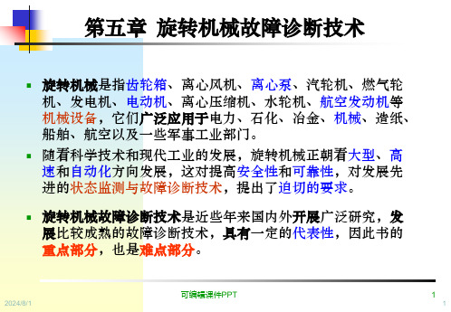
图5.8 典型不对中谱图
可编辑课件PPT
பைடு நூலகம்
19
19
实例四: 转子不对中故障的诊断
MO MI PI PO
电机
水泵
出现2×频率成分。 轴心轨迹成香蕉形或8字形。 振动有方向性。 轴向振动一般较大。 本例中, 出现叶片通过频率。
2X频率 1X频率
叶片通 过频率
2024/8/1
可编辑课件PPT
转子不平衡故障包括: ①转子质量不平衡、 ②转子偏
心、 ③轴弯曲、 ④转子热态不平衡、 ⑤转子部件
脱落、 ⑥转子部件结垢、 ⑦ 联轴器不平衡等,不
同原因引起的转子不可编平辑课衡件P故PT 障规律相近,但也各有 3
2024/8/1
3
第一节 旋转机械典型故障的机理和特征
1.转子质量不平衡
力不平衡: 不平衡产生的振动幅值在转子第一临界转速以下随转速的 平方增大。例如,转速升高1倍,则振动幅值增大3倍。在转子重 心平面内只用一个平衡修正重量便可修正之。
4.转子热态不平衡: 在机组的启动和停机过程中,由于热交换速
度的差异,使转子横截面产生不均匀的温度分布,使转子发生
瞬时热弯曲,产生较大的不平衡。热弯曲引起的振动一般与负
荷有关。
可编辑课件PPT
5
2024/8/1
5
第一节 旋转机械典型故障的机理和特征
5. 转子部件脱落 可以将部件脱落失衡现象看作对工作状态的转子
掌握滚动轴承故障诊断技术、齿轮故障诊断技术;
了解电动机故障诊断技术、皮带驱动故障诊断技术;
2024/8/熟1 悉利用征兆的故障诊可断编辑方课件法PPT。
2
2
第一节 旋转机械典型故障的机理和特征
Turck BC5-S18-Y1X 电容传感器说明书
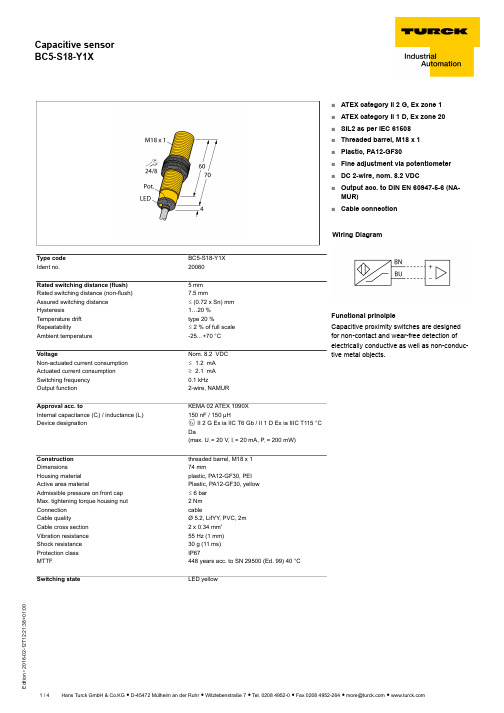
T 12:21:38+01:00Type code BC5-S18-Y1X Ident no.20060Rated switching distance (flush) 5 mm Rated switching distance (non-flush)7.5 mmAssured switching distance ð (0.72 x Sn) mm Hysteresis1…20 %Temperature drift type 20 %Repeatabilityð 2 % of full scale Ambient temperature-25…+70 °C VoltageNom. 8.2 VDC Non-actuated current consumption ð 1.2 mA Actuated current consumption ï 2.1 mA Switching frequency 0.1 kHzOutput function2-wire, NAMURApproval acc. toKEMA 02 ATEX 1090X Internal capacitance (C ) / inductance (L )150 nF / 150 µHDevice designationÉ II 2 G Ex ia IIC T6 Gb / II 1 D Ex ia IIIC T115 °C Da(max. U = 20 V, I = 20 mA, P = 200 mW)Construction threaded barrel, M18 x 1Dimensions74 mmHousing material plastic, PA12-GF30, PEI Active area materialPlastic, PA12-GF30, yellow Admissible pressure on front cap ð 6 bar Max. tightening torque housing nut 2 Nm Connection cableCable qualityØ 5.2, LifYY , PVC, 2mCable cross section 2 x 0.34 mm Vibration resistance 55 Hz (1 mm)Shock resistance 30 g (11 ms)Protection class IP67MTTF448 years acc. to SN 29500 (Ed. 99) 40 °C Switching stateLED yellow■ATEX category II 2 G, Ex zone 1■ATEX category II 1 D, Ex zone 20■SIL2 as per IEC 61508■Threaded barrel, M18 x 1■Plastic, PA12-GF30■Fine adjustment via potentiometer ■DC 2-wire, nom. 8.2 VDC■Output acc. to DIN EN 60947-5-6 (NA-MUR)■Cable connectionWiring DiagramFunctional principleCapacitive proximity switches are designed for non-contact and wear-free detection of electrically conductive as well as non-conduc-tive metal objects.T 12:21:38+01:00Mounting instructions / Description minimum distances Distance D 36 mm Distance W 15 mm Distance S 27 mm Distance G30 mm Diameter of the active area BØ 18 mmThe given minimum distances have been checked in compliance with the standard switching distance.Should the sensitivity of the sensors be changed via potentiometer, the data sheet specifications no longer apply.T 12:21:38+01:00AccessoriesType codeIdent no.DescriptionDesignBS 1869471Mounting bracket for threaded barrel devices; material: PA66-GFBSN 1869472Fixing clamp; material: PA66-GFBST-18B 6947214Fixing clamp for threaded barrel devices, with dead-stop; ma-terial: PA6MAP-M186950012Mounting adapter; material: Polypropylene; sensor replace-ment with filled container possible (adapter remains in con-tainer during sensor replacement)IM1-22EX-R 7541231Isolating switching amplifier, 2-channel; 2 relay outputs; in-put NAMUR signal; selectable ON/OFF mode for wire-break and short-circuit monitoring; adjustable output mode (NO /NC mode); removable terminal blocks; width 18 mm; univer-sal power supply unitT 12:21:38+01:00Operating manual Intended useThis device fulfills the directive 94/9/EC and is suited for use in explosion hazardous areas according to EN60079-0:2012, -11:2012, -26:2007.Further it is suited for use in safety-related systems, including SIL2 as per IEC 61508.In order to ensure correct operation to the intended purpose it is required to observe the national regulations and directives.For use in explosion hazardous areas conform to classificationII 2 G and II 1 D (Group II, Category 2 G, electrical equipment for gaseous atmospheres and category 1 D, electrical equipment for dust atmo-spheres).Marking (see device or technical data sheet)É II 2 G and Ex ia IIC T6 Gb acc. to EN60079-0 and -26 und É II 1 D Ex ia IIIC T115°C Da acc. to EN60079-0Local admissible ambient temperature -25…+70 °CInstallation / CommissioningThese devices may only be installed, connected and operated by trained and qualified staff. Qualified staff must have knowledge of protection classes, directives and regulations concerning electrical equipment designed for use in explosion hazardous areas.Please verify that the classification and the marking on the device comply with the actual application conditions.This device is only suited for connection to approved Exi circuits compliant to EN60079-0 and -11. Please observe the maximum admissible electrical values.After connection to other circuits the sensor may no longer be used in Exi installations. When interconnected to (associated) electrical equip-ment, it is required to perform the "Proof of intrinsic safety" (EN60079-14).When employed in safety systems to IEC 51408 it is required to assess the failure probability (PFD) of the complete circuitry.Installation and mounting instructionsAvoid static charging of cables and plastic devices. Please only clean the device with a damp cloth. Do not install the device in a dust flow and avoid build-up of dust deposits on the device.If the devices and the cable could be subject to mechanical damage, they must be protected accordingly. They must also be shielded against strong electro-magnetic fields.The pin configuration and the electrical specifications can be taken from the device marking or the technical data sheet.service / maintenanceRepairs are not possible. The approval expires if the device is repaired or modified by a person other than the manufacturer. The most important data from the approval are listed.。
机械设备故障诊断的前沿算法是什么

机械设备故障诊断的前沿算法是什么在现代工业生产中,机械设备的稳定运行至关重要。
一旦设备出现故障,不仅会影响生产效率,还可能导致严重的安全事故和经济损失。
因此,及时准确地诊断机械设备的故障具有极其重要的意义。
而在机械设备故障诊断领域,前沿算法的不断涌现为提高诊断的准确性和效率提供了有力的支持。
近年来,一些新型的算法在机械设备故障诊断中展现出了良好的应用前景。
其中,基于深度学习的故障诊断算法引起了广泛关注。
深度学习算法能够自动从大量的监测数据中提取特征,从而实现对故障的准确识别。
例如,卷积神经网络(CNN)在图像识别领域取得了巨大成功,将其应用于机械设备的振动图像分析,可以有效地识别出故障类型。
除了深度学习算法,基于模型的故障诊断算法也在不断发展。
这类算法通过建立机械设备的精确数学模型,然后将实际监测数据与模型预测值进行对比,从而判断设备是否存在故障。
其中,卡尔曼滤波算法及其衍生算法在处理动态系统的故障诊断问题上表现出色。
它能够对系统的状态进行实时估计,并在监测数据出现异常时及时发出故障警报。
还有一类基于信号处理的算法在机械设备故障诊断中发挥着重要作用。
小波变换算法就是其中的代表之一。
它能够将复杂的信号分解成不同频率和时间尺度的成分,从而更容易发现信号中的异常特征。
例如,在机械设备的振动信号分析中,通过小波变换可以清晰地观察到故障引起的高频冲击成分。
另外,基于多传感器融合的故障诊断算法也逐渐成为研究热点。
机械设备的运行状态通常可以通过多种传感器进行监测,如振动传感器、温度传感器、压力传感器等。
将这些来自不同传感器的数据进行融合和综合分析,可以更全面、准确地判断设备的故障情况。
例如,采用数据融合技术,可以将振动信号和温度信号结合起来,提高对轴承故障诊断的准确性。
在实际应用中,这些前沿算法并不是孤立存在的,而是相互结合、相互补充。
例如,将深度学习算法提取的特征与基于模型的算法进行融合,可以提高故障诊断的可靠性。
基于张量Tucker分解的发动机故障诊断
r分 解 的
发动机数据特征提取及诊断方法预测准确率更高,分类模型学习时间更短.
关键词:发动机;故障诊断;张量模式;
Tucke
r分解
中图分类号:
TK411
DOI:
10.
3969/
.
s
sn.
1004
132X.
G
HOOI张量 Tucke
r分解的联立求解算法,对 数 据 特 征 进 行 提 取. 分 别 以 不 进 行 数 据 特 征 提 取 和 基 于
张量 Tucke
r分解进行数据特征提取两种情况,对发动机正常工作、单缸失火和轴系不 对 中 三 种 状 态 下
的实验数据进行处理,并分别采用网格参数优化法、遗传算法、粒子群算 法 对 分 类 模 型 中 的 参 数 进 行 优
(
1)
()
()
()
( )
v1 (
αv12 +βv22 ) v N =
()
()
( )
()
()
( )
αv 1 v12 v N +βv 1 v22 v N
(
2)
(
1)
αv
系列矩阵.一个三阶张量三个方向的切片分别为
水平切片 Xi::、侧身切片 X :j: 和正面切片 X ::k ,正
1.
纯电动汽车动力系统设计与测试湖北省重点实验室,襄阳,
2.
441053
摘要:传统的发动机故障诊断方法通常基于向量模式进行数据特征的提取,可能丢失数据之间的结
构信息及破坏数据间相关性.针对此问题,提出了一种张量模式下提取发动机数据特征的方法,构建了
DeviceNet总线网络诊断

Get on the Bus Now!
设计、建立一个典型的现场总线控制系统
u选择采用现场总线的协议 u选择控制系统的结构 u决定采用的通讯方式 u选择设备元件 u设计网络线路 u配置网络电源 u接地设计 u网络测试 u故障诊断
图尔克(天津)传感器有限公司总线系统部
网络测试(一)
Get on the Bus Now!
m 如果阻值> 60 ohms,说明一根信号线发生了断路或未加 网络终端电阻。
m 如果阻值< 50 ohms,要看一下:网络中是否发生了短路 ,过多终端电阻,节点收发装置是否有故障以及是否有未 供电的节点。
图尔克(天津)传感器有限公司总线系统部
网络测试(三)
Get on the Bus Now!
屏蔽
检查总线电压、模块电压、接地
图尔克(天津)传感器有限公司总线系统部
网络问题
Get on the Bus Now!
m 不能启动网络 检查节点的总线电压和总线末端的电压 检查每个节点的波特率设置 检查每个节点的耦合器是否正常 检查接插件是否正确接线
图尔克(天津)传感器有限公司总线系统部
Get on the Bus Now!
图尔克(天津)传感器有限公司总线系统部
设计网络线路 (一)
网络线路设计的几个方面:
m 最大通讯波特率 m 网络电源分布
网络线路设计的目标:
m 控制主干缆长度 m 控制累积分支电缆长度
(所有分支电缆的总和)
图尔克(天津)传感器有限公司总线系统部
Get on the Bus Now!
设计网络线路 (二)
m 大多数你想使用示波器诊断的故障都是偶尔出现的
m 除非你能够用坏信号触发示波器,否则你是在浪费时间看好 信号
旋转机械故障相关诊断技术(二篇)

旋转机械故障相关诊断技术灰色诊断技术就是在故障诊断中应用灰色系统理论,利用信息间存在的关系,充分发挥采集到的振动信息的作用,充分挖掘振动信息的内涵,通过灰色方法加工、分析、处理,使少量的振动信息得到充分的增值和利用,使潜在的故障原因显化。
二、旋转机械故障的模糊诊断技术模糊诊断技术就是在故障诊断中引入模糊数学方法,将各类故障和征兆视为两类不同的模糊集合,同时用一个模糊关系矩阵来描述二者之间的关系,进而在模糊的环境中对设备故障的原因、部位和程度进行正确、有效地推理、判断。
三、旋转机械故障的神经网络诊断技术所谓的神经网络就是模仿人类大脑中的神经元与连结方式,以构成能进行算术和逻辑运算的信息处理系统。
神经网络模型由许多类似于神经元的非线性计算单元所组成,这些单元以一种类似于生物神经网络的连结方式彼此相连,以完成所要求的算法。
在旋转机械故障的诊断中,引入神经网络技术,以类似于人脑加工信息的方法对收集到的故障信息进行处理,从而对故障的原因、部位和程度进行正确的判断。
旋转机械故障相关诊断技术(二)摘要:旋转机械故障诊断技术在现代工业中扮演着重要的角色,能够帮助工程师及时发现故障,减少生产停机时间,提高设备的可靠性和性能。
本文将介绍一些常见的旋转机械故障诊断技术,包括振动分析、红外热像仪、声波分析、油液分析和电机电流分析等。
这些技术可以用来检测旋转机械的各种故障,包括轮毂偏心、轴承故障、轴传动故障等,并且可以提供及时的故障定位和诊断。
关键词:旋转机械、故障诊断、振动分析、红外热像仪、声波分析、油液分析、电机电流分析一、引言旋转机械在许多行业中广泛应用,包括电力、石化、矿山等。
故障的发生会导致设备停机,给企业带来巨大的经济损失。
因此,旋转机械的故障诊断技术对于保证设备安全稳定运行具有重要意义。
二、振动分析振动分析是一种常用的旋转机械故障诊断技术。
通过安装振动传感器,采集旋转机械的振动信号,然后通过信号处理和分析,可以检测出旋转机械的各种故障,如轮毂偏心、轴承故障、轴传动故障等。
机械设备故障诊断的前沿技术是什么

机械设备故障诊断的前沿技术是什么在现代工业生产中,机械设备的稳定运行是保障生产效率和产品质量的关键。
然而,由于长时间的运行、复杂的工作环境以及各种不可预见的因素,机械设备难免会出现故障。
及时准确地诊断出故障,并采取有效的维修措施,对于减少生产损失、提高设备利用率具有重要意义。
随着科技的不断进步,机械设备故障诊断领域涌现出了一系列前沿技术,为设备的可靠运行提供了更强大的支持。
一、基于深度学习的故障诊断技术深度学习作为人工智能领域的重要分支,在机械设备故障诊断中展现出了巨大的潜力。
传统的故障诊断方法往往依赖于人工提取特征,这不仅需要丰富的专业知识和经验,而且容易受到主观因素的影响。
深度学习模型,如卷积神经网络(CNN)和循环神经网络(RNN),能够自动从大量的监测数据中学习到有效的特征表示,从而实现更准确的故障诊断。
例如,通过将振动信号、温度数据等输入到深度学习模型中,模型可以自动识别出正常运行状态和故障状态之间的差异,并对故障类型进行分类。
此外,深度学习还可以用于预测设备的剩余使用寿命,为设备的维护计划提供科学依据。
二、无线传感器网络与故障诊断的融合无线传感器网络(WSN)的发展为机械设备故障诊断带来了新的机遇。
通过在设备上布置多个无线传感器,可以实时采集设备的运行参数,如振动、声音、压力等。
这些传感器节点之间可以相互通信,将采集到的数据传输到中央处理单元进行分析。
与传统的有线监测系统相比,无线传感器网络具有安装方便、成本低、可扩展性强等优点。
同时,结合先进的信号处理和数据分析算法,可以从海量的监测数据中提取出有价值的信息,实现对设备故障的早期预警和诊断。
三、基于模型的故障诊断方法基于模型的故障诊断方法是通过建立机械设备的数学模型,来预测设备在正常运行条件下的输出,并将实际监测到的输出与模型预测值进行比较。
如果两者之间存在较大偏差,则表明设备可能出现了故障。
这种方法需要对设备的工作原理和结构有深入的了解,建立精确的数学模型。
几种主要现场总线协议的特点

几种主要现场总线协议的特点现场总线在发展的最初,各个公司都提出自己的现场总线的协议,如AB公司的DeviceNet,TURCK公司的Sensoplex,Honeywell公司的SDS,Phoenix公司的InterBus-S,以及Seriplex,ASI等。
经过十几年的发展,现场总线的协议逐渐趋于统一,针对制造业自动化,DeviceNet在北美和日本用的比较普遍,PROFIBUS-DP在欧洲用的比较普遍。
针对过程自动化,PROFIBUS-PA和Foundation Fieldbus占据大部分市场。
其他的总线协议如ASI、InterBus-S、Sensoplex在某些特殊的领域也有一些市场,下面分别介绍各种总线的一些特点。
1、PROFIBUS,最快的总线,世界范围的标准。
PROFIBUS是在1987年,由德国科技部集中了13家公司和5家科研机构的力量,按照ISO/OSI 参照模型制订的现场总线的德国国家标准。
最近,在欧洲通过投票,成为欧洲的标准EN50170。
主要由拥有400多个公司成员的PROFIBUS用户组织(PNO)进行管理。
PROFIBUS由三部分组成,即PROFIBUS-FMS,PROFIBUS-DP及PROFIBUS-PA。
其中,FMS 主要用于非控制信息的传输,PA主要用于过程自动化的信号采集及控制。
PROFIBUS-DP是制造业自动化主要应用的协议内容,是满足用户快速通讯的最佳方案,每秒可传输12兆位。
扫描1000个I/O点的时间少于1ms。
PROFIBUS是世界范围的标准,取得了很大的成功:至少1,000,000套设备投入运行,超过600家成员公司,超过1100种PROFIBUS产品。
2、DeviceNet通用型、低价位的总线DeviceNet(设备网)是一种低价位的总线,它可连接自动化生产系统中广泛的工业设备。
在制造业领域,设备网遍及全球,尤其是北美和日本。
最初是由AB公司设计,现在已经发展成为一种开放式的现场总线的协议,其管理组织ODVA由全球多家公司组成,提供设备网的产品,支持设备网规范的进一步开发。
DeviceNet网络故障诊断指导

DeviceNet网络故障诊断指导DveicNet网络故障诊断指导?DeviceNet介绍DeviceNet故障诊断方式常规检测检查清单电气检查清单分割网络诊断DeviceNet是一种5芯数字通讯网络。
在V+和V-之间有24V网络电源,CAN_H和CAN_L两根电缆用于信号通讯,第五根电缆是屏蔽电缆,在和V-连接后设置网络上的唯一接地点。
(续)DeviceNet网络是一种主干/分支的拓扑结构,设备(或节点)通过T接头或分路器连接到主干网的不同节点上,在网络(主干)两端必须有终端电阻。
2. DeviceNet故障诊断方式大部分网络故障可以用两种工具(数字万用表和网络检测仪)来进行检测。
通常的网络故障是硬件故障可以通过常规进程进行诊断。
1.遇到网络故障可以从常规检测的检查清单开始。
单独的节点问题通常通过更换节点上的设备或和设备关联的元器件(T接头,分支电缆)来解决。
2.若故障依旧或间歇存在,可以用网络诊断仪检测根本原因。
这个仪器可以检测bus故障和其他边界条件的网络故障。
另外,网络诊断仪可以不中断网络运行连接到网络(可监测)中。
3.Bus-off的问题通常可以通过“分割网络”方式进行排故,用网络诊断仪进行检测可以获得更多的信息。
4.对于间歇或持久故障,上述方式仍然没有检测到根本原因,用电气测试的方式可以解决网络的常规故障(接线,接地等)。
提醒:1.若Scanner有bus off(代号91)报警,对DeviceNet Scanner 进行重新上电可以清楚这个故障。
小贴士:通常的做法是将Scanner在机架上拔下再安装。
2.切断主干网或终端电阻会导致网络bus off报警。
当按照“分割网络”的步骤进行时必须在每一步后重置网络。
3.对PLC槽架的重上电可以复位Scanner但不能复位网络上的其他设备。
小贴士:重置整个网络,必须重置网络电源,这个电源通常在MCP柜中。
4. RSNetworxs for DeviceNet这个软件对bus off的故障排除不是一个有用的工具。
AB-DeviceNet
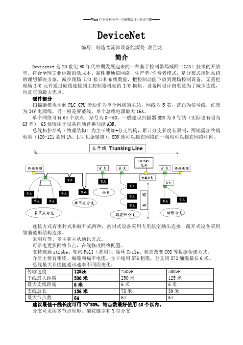
DeviceNet编写:制造物流部设备能源处谢巨龙简介Devicenet是20世纪90年代中期发展起来的一种基于控制器局域网(CAN)技术的开放型、符合全球工业标准的低成本、高性能通信网络,生产者/消费者模式,是分布式控制系统的理想解决方案,减少现场I/O接口和布线数量,把控制功能下放到现场控制设备,无需把现场I/O元件通过硬线连接到主控制器机架的I/O模块。
设备网设计初衷是为了减少连线,也是它的最大优点。
硬件部分扫描器模块插到PLC CPU旁边作为单个网络的主站,网线为5芯,蓝白为信号线,红黑为24V电源线,另一根是屏蔽线,单个总线电源最大16A。
单个网络可有64个站点,站号为0~63,一般建议扫描器SDN为0号站(实际也有设为63者),63保留用于设备自动替换功能ADR。
总线拓扑结构(物理结构)为主干线加+分支结构,累计分支长度有限制,两端需加终端电阻(120-121欧姆1%、1/4瓦金属膜)。
SDN既可以接在网络的一端也可以接在网络中间。
连接方式有密封式和敞开式两种,密封式设备采用专用航空插头连接,敞开式设备采用雏菊链形结构连接。
采用对等、多主和主从通讯方式。
可带电更换网络节点,在线修改网络配置。
支持选通strobe、轮询Poll(常用)、循环Cycle、状态改变COS等数据传递方式。
介质主要有粗缆、细缆和扁平电缆。
主干线用576粗缆,分支用572细缆最长6米。
传输速度125kb 250kb 500kb干线最大距离500米250米125米最大支线距离6米6米6米支线总长156米78米39米最大节点数64 64 64分支可采用多节点星形、菊花链型和Y型分支总线长度取两端及分支Ln(两端及两端分支)中最长者计算总线最多接40个站点支线长度总和≤156M单个支线长度≤20feet,约6M主干线电流允许最大8A,单电源供电时电流随长度的增加而降低,需要分段供电维持足Nt—Tap(T形头)的数量In—子站最大电流例:单电源总线,4个Tap(244×0.015+4×)×网络电流最大8A,随长度的增加而降低配置实例和故障处理组态软件:Devicenet需要通过软件配置好并把组态文件保存在SDN中才可使用。
TURCKDevicenet诊断详细讲义
设计、建立一个典型的现场总线控制系统
u选择采用现场总线的协议 u选择控制系统的结构 u决定采用的通讯方式 u选择设备元件 u设计网络线路 u配置网络电源 u接地设计 u网络测试 u故障诊断
接地设计(一)
网络接地设计规则
m在电源处将DC供电公共线和屏蔽连接到低阻抗地。
m 如果是多电源供电,只将靠近网络中间的一个电源接地。 m 接地位置影响公共电压
图尔克集团公司——与您携手共进
Moving Ahead with You!
谢谢大家!
设计、建立一个典型的现场总线控制系统
u选择采用现场总线的协议 u选择控制系统的结构 u决定采用的通讯方式 u选择设备元件 u设计网络线路 u配置网络电源 u接地设计 u网络测试 u故障诊断
设计网络线路 (一)
网络线路设计的几个方面:
图尔克集团公司——与您携手共进
Moving Ahead with You!
谢谢大家!
m最大通讯波特率 m网络电源分布
网络线路设计的目标:
m控制主干缆长度 m控制累积分支电缆长度
(所有分支电缆的总和)
设计网络线路 (二)
重点:
m根据 DeviceNet的规定,网络主干缆可以是粗缆细 缆,也可以是粗、细缆组合使用。
m主干缆的每一端都必须加终端电阻。
m 只能有两个终端电阻。 m DeviceNet与许多其他网络不同,无论电缆长度是多少,
故障诊断(五)
头脑是最好的诊断工具:
m详细记录故障状态
m 如果让别人帮你记录,那记录将是没有价值的。
m寻找故障的伴随情况
m 在断续故障发生的时候是否有其他不相关的设备投入了运行 m 是否有节点工作正常?工作的节点与其他节点之间的区别是
机械设备故障诊断的前沿技术是什么

机械设备故障诊断的前沿技术是什么在现代工业生产中,机械设备的稳定运行是保障生产效率和质量的关键。
然而,由于长时间的运行、复杂的工作环境以及各种不可预见的因素,机械设备难免会出现故障。
及时准确地诊断出故障,并采取有效的维修措施,对于减少停机时间、降低维修成本、提高设备可靠性和安全性具有重要意义。
随着科技的不断进步,机械设备故障诊断技术也在不断发展,涌现出了一系列前沿技术。
一、基于大数据分析的故障诊断技术随着工业互联网和物联网技术的普及,大量的机械设备运行数据被实时采集和存储。
这些数据包含了设备的各种运行状态信息,如温度、压力、振动、电流等。
通过对这些大数据的分析,可以挖掘出设备运行的潜在规律和模式,从而实现故障的诊断和预测。
大数据分析在机械设备故障诊断中的应用主要包括数据预处理、特征提取、模型建立和故障诊断等步骤。
首先,需要对采集到的原始数据进行清洗和预处理,去除噪声和异常值,以提高数据质量。
然后,通过特征工程技术提取能够反映设备故障的关键特征。
接下来,利用机器学习或深度学习算法建立故障诊断模型,如支持向量机、决策树、神经网络等。
最后,将实时采集的数据输入模型中,进行故障诊断和预测。
基于大数据分析的故障诊断技术具有数据驱动、自适应性强、能够发现潜在故障等优点。
然而,该技术也面临着数据质量、数据安全、计算资源等方面的挑战。
二、基于深度学习的故障诊断技术深度学习是近年来人工智能领域的热门技术,在机械设备故障诊断中也得到了广泛的应用。
深度学习模型,如卷积神经网络(CNN)、循环神经网络(RNN)和长短时记忆网络(LSTM)等,能够自动从大量的数据中学习到复杂的特征和模式,从而实现高精度的故障诊断。
以卷积神经网络为例,它可以直接处理原始的振动信号等数据,通过卷积层和池化层自动提取故障特征。
循环神经网络和长短时记忆网络则适用于处理具有时间序列特性的数据,能够捕捉故障发展的动态过程。
深度学习在机械设备故障诊断中的应用需要大量的标注数据进行训练,以提高模型的准确性和泛化能力。
- 1、下载文档前请自行甄别文档内容的完整性,平台不提供额外的编辑、内容补充、找答案等附加服务。
- 2、"仅部分预览"的文档,不可在线预览部分如存在完整性等问题,可反馈申请退款(可完整预览的文档不适用该条件!)。
- 3、如文档侵犯您的权益,请联系客服反馈,我们会尽快为您处理(人工客服工作时间:9:00-18:30)。
设计网络线路 (一)
网络线路设计的几个方面:
m 最大通讯波特率 m 网络电源分布
网络线路设计的目标:
m 控制主干缆长度 m 控制累积分支电缆长度
(所有分支电缆的总和)
图尔克(天津)传感器有限公司总线系统部
Get on the Bus Now!
设计网络线路 (二)
Get on the Bus Now!
设计、建立一个典型的现场总线控制系统
u选择采用现场总线的协议 u选择控制系统的结构 u决定采用的通讯方式 u选择设备元件 u设计网络线路 u配置网络电源 u接地设计 u网络测试 u故障诊断
图尔克(天津)传感器有限公司总线系统部
网络测试(一)
Get on the Bus Now!
m 使用多个电源时应注意:
m 必须保证网络中任何两点之间电源公共端的变化小于 5V
图尔克(天津)传感器有限公司总线系统部
Get on the Bus Now!
设计、建立一个典型的现场总线控制系统
u选择采用现场总线的协议 u选择控制系统的结构 u决定采用的通讯方式 u选择设备元件 u设计网络线路 u配置网络电源 u接地设计 u网络测试 u故障诊断
电源问题
Get on the Bus Now!
m 当运行的时候靠近网络末端的节点停止通讯 检查节点的总线电压、总线末端电压、模块电 压
m 当运行的时候扫描器和若干节点处于BUS OFF状态 检查总线电压、模块电压、接地
m 扫描器不能正确地配置从站节点 检查总线电压、模块电压、接地
m 通讯距离减少或者只有一点数量的节点时能通 讯
Get on the Bus Now!
DeviceNet总线网络诊断
图尔克(天津)传感器有限公司总线系统部
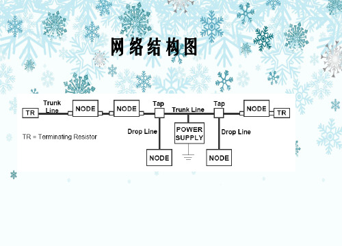
网络结构图
Get on the Bus Now!
图尔克(天津)传感器有限公司总线系统部
故障点
Get on the Bus Now!
m 接插件 m 线缆 m 接地 m 屏蔽层 m 跟动力电缆隔离 m 电压 m 电阻(线缆电阻、终端电阻) m 模块(地址、波特率、电压)
图尔克(天津)传感器有限公司总线系统部
Get on the Bus Now! 图尔克(天津)传感器有限公司总线系统部
物理问题
Get on the Bus Now!
m 所有的节点都停止通讯 检查所有的接线、接头、终端电阻
m 节点偶然停止通讯 检查接线和接头是否松了
m 通讯距离减少或者只有一点数量的节点时才 能通讯 检查电阻(线缆电阻、终端电阻)
图尔克集团公司——与您携手共进
Moving Ahead with You!
谢谢大家!
图尔克(天津)传感器有限公司总线系统部
Get on the Bus Now!
设计、建立一个典型的现场总线控制系统
u选择采用现场总线的协议 u选择控制系统的结构 u决定采用的通讯方式 u选择设备元件 u设计网络线路 u配置网络电源 u接地设计 u网络测试 u故障诊断
电源系统设计目标
m 给每个装置提供至少11Vdc电源
Get on the Bus Now!
图尔克(天津)传感器有限公司总线系统部
配置网络电源(二)
Get on the Bus Now!
电源系统设计步骤
m 确定每个装置的最大电流 m 在网络中施加一个或多个电源,以确保:
m 在经过每个站的输入和输出的电缆之间的电压降不要超过
设计、建立一个典型的现场总线控制系统
u选择采用现场总线的协议 u选择控制系统的结构 u决定采用的通讯方式 u选择设备元件 u设计网络线路 u配置网络电源 u接地设计 u网络测试 u故障诊断
图尔克(天津)传感器有限公司总线系统部
配置网络电源(一)
网络电源是一个新概念
m 网络电缆中需提供 24Vdc
m 给简单装置供电 m 给大装置中绝缘的网络接口供电
设计网络线路 (三)
Get on the Bus Now!
其他要点:
m 必须严格遵守主干和分支拓朴结构的规定。
m 违背规定所带来的麻烦会很多。
m 用细缆做主干线对网络电源设计有很大影响:
m 细缆具有较大的DC电阻,将对供电产生更大的电压降。
图尔克(天津)传感器有限公司总线系统部
Get on the Bus Now!
5Vdc
m 电流不要超过电缆/接插件的允许值。
m DeviceNet 规定中提供了一个简便的表格,可以用 来查找电源系统设计方案。
图尔克(天津)传感器有限公司总线系统部
配置网络电源(三)
Get on the Bus Now!
要点:
m 使用最大启动电流规定来计算每个装置的用电。
m 提供的最小电流必须保证的装置的要求
检查总线电压、模块电压、接地
图尔克(天津)传感器有限公司总线系统部
网络问题
Get on the Bus Now!
m 不能启动网络 检查节点的总线电压和总线末端的电压 检查每个节点的波特率设置 检查每个节点的耦合器是否正常 检查接插件是否正确接线
图尔克(天津)传感器有限公司总线系统部
Get on the Bus Now!
Get on规定,网络主干缆可以是粗缆细 缆,也可以是粗、细缆组合使用。
m 主干缆的每一端都必须加终端电阻。
m 只能有两个终端电阻。 m DeviceNet与许多其他网络不同,无论电缆长度是多少,
只要工作正常,就需要网络终端电阻。
图尔克(天津)传感器有限公司总线系统部
图尔克(天津)传感器有限公司总线系统部
接地设计(一)
Get on the Bus Now!
网络接地设计规则
m 在电源处将DC供电公共线和屏蔽连接到低阻抗地。
m 如果是多电源供电,只将靠近网络中间的一个电源接地。 m 接地位置影响公共电压
m 网络中的所有接头和分支必须很好地连接屏蔽、信号和 电源线
图尔克(天津)传感器有限公司总线系统部
图尔克(天津)传感器有限公司总线系统部
节点问题
Get on the Bus Now!
m 从站的节点在线,但是扫描器没有发现 地址设置超出范围
m 从站节点不在线 检查CANH/CANL接线 改变波特率
m 去掉某个节点通讯正常 检查节点的耦合器
m 节点处于I/O超时状态 重启扫描器和网络电源
图尔克(天津)传感器有限公司总线系统部
