Power Monitor分析仪mPower1203和安捷伦N6705C针对穿戴设备功耗实测对比
Agilent HSMx-C120 C177 C197 C265 高性能片级LED数据手册说明书
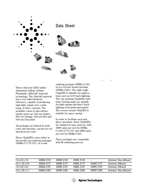
Agilent H SMx-C120/C177/C197/C265High Performance Chip LEDsData SheetFeatures•High brightness AlInGaP material •0805 or 0603 industry standard footprint with 0.4 mm height for top emitting packages•Also available in right angle emitting and reverse mounting packages•Diffused optics•Operating temperature range of –30°C to +85°C•Compatible with IR soldering •Available in 4 colors•Available in 8 mm tape on 7"diameter reel•Reel sealed in zip locked moisture barrier bags Applications•Membrane switch indicator •LCD backlighting•Push button backlighting •Front panel indicator •Symbol backlighting •Keypad backlighting •Microdisplays•Small message panel signageDescriptionThese chip type LEDs utilize Aluminium Indium Galium Phosphide (AlInGaP) material technology. The AlInGaP material has a very high luminousefficiency, capable of producing high light output over a wide range of drive currents. The available colors in this surface mount series are 592 nm Amber,605 nm Orange, 626 nm Red and 639 nm Deep Red.All packages are binned by both color and intensity, except for red and deep red color.These ChipLEDs come either in low profile top emitting packages (HSMx-C177/C197), in a sideemitting package (HSMx-C120)or in a reverse mount package (HSMx-C265). The right angle ChipLED is suitable for applica-tions such as LCD back lighting.The top emitting ChipLEDs with wide viewing angle are suitable for light piping and direct back-lighting of keypads and panels.The reverse mount ChipLED is suitable for space saving.In order to facilitate pick and place operation, these ChipLEDs are shipped in tape and reel, with 4000 units per reel for HSMx-C120/C177/C197 and 3000 units per reel for HSMx-C265.These packages are compatible with IR soldering process.Device Selection GuideDimensions (mm)[1,2]Amber RedOrange Deep Red Package Description 1.6 x 0.6 x 1.0HSMA-C120HSMC-C120HSML-C120–Untinted, Non-diffused 2.0 x 1.25 x 0.4HSMA-C177HSMC-C177HSML-C177HSMT-C177Untinted, Diffused 1.6 x 0.8 x 0.4HSMA-C197HSMC-C197HSML-C197HSMT-C197Untinted, Diffused 3.4 x 1.25 x 1.1HSMA-C265HSMC-C265HSML-C265HSMT-C265Untinted, Non-diffusedPackage DimensionsPOLARITYTERMINAL0.40 ± 0.15HSMx-C177POLARITY0.30 ± 0.15TERMINALHSMx-C1970.50 ± 0.15POLARITY0.50 ± 0.15TERMINALHSMx-C265POLARITYTERMINALHSMx-C120NOTES:1. ALL DIMENSIONS IN MILLIMETERS (INCHES).2. TOLERANCE IS ± 0.1 mm (± 0.004 IN.) UNLESS OTHERWISE SPECIFIED.Absolute Maximum Ratings at T A = 25˚CParameter HSMx-Cxxx UnitsDC Forward Current [1]25mAPeak Pulsing Current[2]100mAPower Dissipation60mWReverse Voltage (I R = 100 µA)5VLED Junction Temperature95˚COperating Temperature Range–30 to +85˚CStorage Temperature Range–40 to +85˚CSoldering Temperature See reflow soldering profile (Figures 8 & 9)Notes:1. Derate linearly as shown in Figure 4.2. Pulse condition of 1/10 duty and 0.1 ms width.Electrical Characteristics at T A = 25˚CForward Voltage Reverse Breakdown Capacitance C ThermalV F (Volts)V R (Volts)(pF), V F = 0,Resistance@ I F = 20 mA@ I R = 100 µA f = 1 MHz RθJ–PIN(˚C/W) Part Number Typ.Max.Min.Typ.Typ.HSMA-C120 1.9 2.4511400HSMA-C177/197 1.9 2.4511300HSMA-C265 1.9 2.4511550HSMC-C120 1.9 2.4515400HSMC-C177/197 1.9 2.4515300HSMC-C265 1.9 2.4515550HSML-C120 1.9 2.4520400HSML-C177/197 1.9 2.4520300HSML-C265 1.9 2.4520550HSMT-C177/197 1.9 2.4515300HSMT-C265 1.9 2.4515550V F Tolerance: ± 0.1 VOptical Characteristics at T A = 25˚CLuminous Color,Viewing LuminousIntensity Peak Dominant Angle EfficacyI V (mcd)Wavelength Wavelength 2 θ1/2ηV@ 20 mA[1]λpeak (nm)λd[2](nm)Degrees[3](lm/w) Part Number Color Min.Typ.Typ.Typ.Typ.Typ. HSMA-C120Amber28.590595592155480 HSMA-C177/197Amber28.590595592130480 HSMA-C265Amber28.575595592150480 HSMC-C120Red28.590637626155155 HSMC-C177/197Red28.590637626130155 HSMC-C265Red28.575637626150155HSML-C120Orange28.590609605155370HSML-C177/197Orange28.590609605130370HSML-C265Orange28.575609605150370 HSMT-C177/197Deep Red11.23066063913070HSMT-C265Deep Red11.22566063915070Notes:1.The luminous intensity, I V, is measured at the peak of the spatial radiation pattern which may not be aligned with the mechanical axis of the lamp package.2.The dominant wavelength, λd, is derived from the CIE Chromaticity Diagram and represents the perceived color of the device.3.θ1/2 is the off-axis angle where the luminous intensity is 1/2 the peak intensity.Light Intensity (Iv) Bin Limits [1]Intensity (mcd)Bin ID Min.Max.A 0.110.18B 0.180.29C 0.290.45D 0.450.72E 0.72 1.10F 1.10 1.80G 1.80 2.80H 2.80 4.50J 4.507.20K 7.2011.20L 11.2018.00M 18.0028.50N 28.5045.00P 45.0071.50Q 71.50112.50R 112.50180.00S 180.00285.00T 285.00450.00U 450.00715.00V 715.001125.00W 1125.001800.00X 1800.002850.00Y 2850.004500.00Note:1.Bin categories are established for classifica-tion of products. Products may not be avail-able in all categories. Please contact your Agilent representative for information on currently available bins.Amber Color Bins [1]Dom. Wavelength (nm)Bin ID Min.Max.A 582.0584.5B 584.5587.0C 587.0589.5D 589.5592.0E 592.0594.5F594.5597.0Orange Color Bins [1]Dom. Wavelength (nm)Bin ID Min.Max.A 597.0600.0B 600.0603.0C 603.0606.0D 606.0609.0E 609.0612.0F612.0615.0Tolerance: ± 0.5 nmNote:1. Bin categories are established for classification of products. Products may not be available in all categories. Please contact your Agilent representative for information on currently available bins.Tolerance: ± 1 nmTolerance: ± 15%Color Bin LimitsFigure 4. Maximum forward current vs.ambient temperature.Figure 3. Luminous intensity vs. forward current.I F – FORWARD CURRENT – mA00.41.0L U M I N O U S I N T E N S I T Y (N O R M A L I Z E D A T 20 m A )0.60.20.81.41.2Figure 2. Forward current vs. forward voltage.Figure 1. Relative intensity vs. wavelength.WAVELENGTH – nmR E L A T I V E I N T E N S I T Y – %500550600650700100101V F – FORWARD VOLTAGE – VI F – F O R W A R D C U R R E N T – m AI F M A X – M A X I M U M F O R W A R D C U R R E N T – m AT A – AMBIENT TEMPERATURE – °CFigure 5. Relative intensity vs. angle for HSMx-C120.100908070605040302010R E L A T I V E I N T E N S I T Y-90-80-70-60-50-40-30-20-100102030405060708090ANGLE100908070605040302010R E L A T I V E I N T E N S I T Y-90-80-70-60-50-40-30-20-100102030405060708090ANGLEFigure 6. Relative intensity vs. angle for HSMx-C177/197.Figure 9. Recommended Pb-free reflow soldering profile.Figure 10. Recommended soldering pattern for HSMx-C177.R E L A T I V E I N T E N S I T Y – %1000ANGLE806050702010304090-70-50-3002030507090-90-20-80-60-40-1010406080(0.035)0.8 (0.028)BOARDFigure 11. Recommended soldering pattern for HSMx-C197.Figure 7. Relative intensity vs. angle for HSMx-C265.R E L A T I V E I N T E N S I T Y – %1000ANGLE806050702010304090-70-50-3002030507090-90-20-80-60-40-1010406080NOTE:1. ALL DIMENSIONS IN MILLIMETERS (INCHES).TIMET E M P E R A T U R E* THE TIME FROM 25 °C TO PEAK TEMPERATURE = 6 MINUTES MAX.Figure 8. Recommended reflow soldering profile.T E M P E R A T U R EFigure 14. Reeling orientation.Figure 15. Reel dimensions.Figure 12. Recommended soldering pattern for HSMx-C120.Figure 13. Recommended soldering pattern for HSMx-C265.(0.031)(0.031)(0.047)Ø 20.20 MIN. (Ø 0.795 MIN.)Ø 13.1 ± 0.5 NOTE:1. ALL DIMENSIONS IN MILLIMETERS (INCHES).Figure 16. Tape dimensions.TABLE 1DIMENSIONS IN MILLIMETERS (INCHES)DIM. A ± 0.10 (0.004)DIM. B ± 0.10 (0.004)PART NUMBER DIM. C ± 0.10 (0.004)HSMx-C120 SERIES HSMx-C177 SERIES HSMx-C197 SERIES(0.020 ± 0.002)0.80 (0.031) 0.60 (0.024) 0.60 (0.024)1.90 (0.075)2.30 (0.091) 1.80 (0.071) 1.15 (0.045) 1.40 (0.055) 0.95 (0.037)NOTES:1. ALL DIMENSIONS IN MILLIMETERS (INCHES).2. TOLERANCE IS ± 0.1 mm (± 0.004 IN.) UNLESS OTHERWISE SPECIFIED.HSMx-C265 SERIES 3.70 (0.146) 1.45 (0.057) 1.30 (0.051)TABLE 1DIMENSIONS IN MILLIMETERS (INCHES)DIM. A ± 0.10 (0.004)DIM. B ± 0.10 (0.004)PART NUMBERDIM. C ± 0.10 (0.004)/semiconductorsFor product information and a complete list of distributors, please go to our web site.For technical assistance call:Americas/Canada: +1 (800) 235-0312 or (916) 788-6763Europe: +49 (0) 6441 92460China: 10800 650 0017Hong Kong: (+65) 6756 2394India, Australia, New Zealand: (+65) 6755 1939Japan: (+81 3) 3335-8152(Domestic/Interna-tional), or 0120-61-1280(Domestic Only)Korea: (+65) 6755 1989Singapore, Malaysia, Vietnam, Thailand,Philippines, Indonesia: (+65) 6755 2044Taiwan: (+65) 6755 1843Data subject to change.Copyright © 2004 Agilent Technologies, Inc.Obsoletes 5988-5501EN April 22, 20045989-0551ENConvective IR Reflow Soldering For more information on IR reflow soldering, refer toApplication Note 1060, Surface Mounting SMT LED Indicator Components .Storage Condition:5 to 30°C @ 60% RH max.Baking is required under the condition:a) the blue silica gel indicator becoming white/transparent colorb) the pack has been open for more than 1 weekBaking recommended condition:60 ± 5°C for 20 hours.Figure 17. Tape leader and trailer dimensions.END STARTSEALED WITH COVER TAPE.SEALED WITH COVER TAPE.OF CARRIER AND/ORCOVER TAPE.。
逻辑分析仪调查报告
逻辑分析仪调查报告一、概述(一)用途逻辑分析仪是数据域的电子测量仪器,主要用于观察和测量多通道数字信号的逻辑关系,广泛应用于数字设备的研制、生产、维修等工作中,还可以应用于教学实验、集成电路测试、无线电技术侦察、雷达侦测和监视等领域。
(二)分类与特点逻辑分析仪可以分为台式逻辑分析仪、虚拟式逻辑分析仪、高档逻辑分析仪和中低档逻辑分析仪等类型产品。
●台式逻辑分析仪的特点台式逻辑分析仪可以独立工作,也可以使用计算机进行程控,可以广泛应用于各种场合。
价格较高,显示屏幕较小。
●虚拟式逻辑分析仪的特点虚拟式逻辑分析仪必须和计算机一起工作,由逻辑分析仪采集数据,利用计算机进行数据的分析和处理,优点是价格较低,可以充分利用计算机的处理能力和大屏幕显示功能,缺点是不能独立工作,应用场合有时受限制。
●高档逻辑分析仪的特点高档逻辑分析仪非常复杂,采样速率很高,配备有复杂的采样探头适配器,主要应用于大规模集成电路的研制和测试,高档数字设备的维修和故障分析。
价格昂贵,使用方法难以掌握。
●中低档逻辑分析仪的特点中低档逻辑分析仪结构较简单,采样速率不很高,只配备简单的采样探头夹具,主要应用于教学实验,简单数字设备的维修和故障分析,价格便宜,应用广泛。
(三)产品国内外现状国产逻辑分析仪带宽在20MHz~100MHz、采样率在500MSa/s以内的中低档产品为主,并有相当的出口量。
高档逻辑分析仪带宽达30GHz、采样率达80GSa/s,被泰克、安捷伦等公司垄断。
(四)技术发展趋势●集成化、小体积已经成为未来逻辑分析仪产品主要的发展趋势;●高带宽、高采样率仍是逻辑分析仪追求的目标。
二、主要品牌调查2.1 泰克公司2.1.1 泰克的产品方案便携式TLA5000B系列逻辑分析仪以可承受的价格结合了高速定时分辨率、快速状态数据收集、合适的记录状态和先进的触发功能。
它是对目前的嵌入式设计进行验证工作的理想选择。
TLA6000系列逻辑分析仪价格低廉,为您调试、验证和优化数字系统的功能提供了所需的性能。
安捷伦仪器使用说明书中文

Alpha安捷伦B1500A半导体器件分析仪用户!ˉ的GUID安捷伦科技公司声明?安捷伦科技公司2005年,2006年,2007年,2008本手册的任何部分不得转载任何形式或通过任何手段(包括电子电子存储和检索或翻译成外国语言)事先同意MENT和安捷伦的书面同意作为由美国科技公司在美国和国际版权法。
手册部件号B1500-90000版2005年7月第1版,第2版,2005年12月2006年4月第3版第4版,2007年1月2007年6月5日,版第6版,2007年11月2008年10月7日,版安捷伦科技公司5301史蒂文斯溪大道95051美国加利福尼亚州圣克拉拉保证本文档中所含的物质是提供MENT!°为是,±,是苏如有更改,恕不另行通知,在以后的版本。
此外,最大而且,在适用法律法律,安捷伦提供任何保证,明示或暗示,关于本手册的任何信息所载,包括但不不限于隐含保证为杆的适销性和适用性特定用途。
安捷伦不得承担错误或偶然或在相应的损害赔偿连接TION的家具,使用,或每本文件或任何性能所载资料。
应该安捷伦与用户有一个单独的与保修的书面协议在这个物质的范围,涵盖记录与这些冲突条款,在保修则以协议arate中的协议为准。
技术许可硬件和/或软件描述这份文件是依照许可可用于复制或只在雅跳舞的许可条款。
有限权利如果软件在使用的一种表现美国政府的首要合同或道,软件交付和许可!°商业计算机软件!±ADFAR252.227-7014(1995年6月)的定义,或作为一个!°商业项目!FA±定义2.101(a)或°有限计算机软!洁具!±作为定义在FAR52.227-19(六月1987)或任何相当机构法规或合同条款。
使用,重复或disclo的软件肯定是受安捷伦科技nologies!ˉ标准商业许可条款和非DOD部门和美国政府机构没有获得更大而不是限制权利定义在FAR 52.227-19中(C)(1-2)(6月1987年)。
AMC1203中文资料

PRODUCTION DATA information is current as of publication date. Products conform to specifications per the terms of the Texas Instruments standard warranty. Production processing does not necessarily include testing of all parameters.
ABSOLUTE MAXIMUM RATINGS (1)
Over operating free-air temperature range, unless otherwise noted.
PARAMETER Supply voltage, VDD1 to GND1 or VDD2 to GND2 Analog input voltage at VIN+, VIN– Input current to any pin except supply pins Continuous total power dissipation Maximum junction temperature, TJ Human body model (HBM) JEDEC standard 22, test method A114-C.01 Electrostatic discharge (ESD), all pins Charged device Model (CDM) JEDEC standard 22, test method C101 Machine Model (MM) JEDEC standard 22, test method A115A (1) AMC1203 –0.3 to +6 GND1 – 0.3 to VDD1 + 0.3 ±10 +150 ±3000 ±1500 ±200 UNIT V V mA °C V V V
N6705C方案应用操作
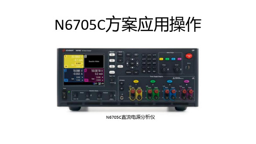
N6705C方案应用操作N6705C直流电源分析仪N6705C家族成员性能特点价值集成电源,万用表,数字示波器,大功率任意波形发生器和数据记录仪于一体。
不需要多台单独仪器搭配使用,有效节省时间提高工作效率。
大屏幕彩色图形显示便捷的设置和监视,能同时看到多个通道的结果。
连接黑控制由颜色区分显示快速设置和控制,自信地正确配置和测试对常用功能直观的和专用的控制使用友好的界面的快速设置和控制,每种仪器的功能和独立仪器相似。
无需编程和访问所有测量能力。
由于不需要使用PC,驱动程序和软件,可以把与设置有关的工作量减少90%以上。
性能和特点N6705C可以实现什么功能?1.电源/负债:可以通过他的任意波形控制,电压变化率控制的高性能直流电源。
2.电压表/电流表:N6705C每个直流模块都内置电压表和电流表。
已测量各路之直流输出和进入DUT的实际电压和电流。
屏观察电压和电流波形。
4.数据记录仪:N6705C具有数据记录仪功能,使用各直流电源模块的内置测量功能,N6705C可连续记录数据,并把数据显示在屏幕上或文件中。
可以同时记录所有四路直流输出数据。
5.大功率任意波形发生器:N6705A的各直流电源模块都有内置任意波形发生器调制功能。
因此可以把该直流输出当作任意波形功率发生器。
其他功能:1.输出序列。
2.可设置电压变化率。
3.串联和并联工作。
4.方便的前面板连接。
5.提高测量精度的四线远端感应。
6.提供低噪声输出的电源模块。
7.提供快电压变化的电源模块。
8.自动量程的灵活性。
9.电源管理特性允许分配主机N6705C的主机功率。
10.用N6730/40/70直流电源模块进行一般直流偏置。
11.用N6760直流电源模块得到精密的低电平性能。
12.实时时钟。
13.内部存贮。
14.前面板USB.15.紧急停止。
16.DUT保护特性。
17.输出断路和极性反转继电器。
18.触发。
N6705C应用1.N6705C 直流电源分析仪-电压瞬变测试应用电压瞬变情况技术难点:1. 供电电源之间的切换 1. 高精度输出2. 防短路熔断器对电路影响 2. 上下编程时间3. 感性器件造成的过冲电压N6705C 直流电源分析仪-对同一负载不同电压补偿方式1.N6705C直流分析仪可以直接编辑产生电压,电流任意波形,用以仿真电源在各种供电系统中的各种电压瞬变现象。
安捷伦网络分析仪选型指南

射频网络分析的业界标准
ENA 网络分析仪 E5071C
Agilent ENA 为双工器和耦合器 等多端口器件提供快速精确的测量解 决方案。E5071C 在 4.5、6.5、8.5、 14 和 20 GHz 的测量频率范围内最多 可以配置成 4 个内置测量端口。
ENA 中内置了测量平衡器件的 先进功能,用户很容易就可以对用在 手机或其它射频终端设备中的元器 件,例如平衡 SAW 滤波器等进行测 量。使用内置的夹具仿真功能,用户 可以完成匹配电路嵌入、测试夹具去 嵌入和阻抗转换等更复杂一些的测量 工作,ENA 也支持混合模式 S 参数的 测量。
E5061B 适用于测量各种低频器 件,例如直流至直流转换器、无线电 系统和无线接口中使用的射频器件、 传感器电路等,这为用户改善终端产 品的性能和质量提供了保障。当然,它 也非常适用于所有需要对被测器件进 行网络分析测量的实验室和教学机构。
● 内置直流偏置源 (高达 ± 40 Vdc) ● 外形紧凑 (254 毫米长) ● 内置 Visual Basic 应用程序设计语言 (VBA)
ENA的频率偏置测量模式 (FOM) 可以让用户精确地对混频器和变频器 的特性进行表征。
用户可以使用 ENA 在制造过程 中轻松高效地完成测量任务。使用内 置的微软 Visual Basic 应用编程语言 (VBA) 可以快速开发自动化测量程序; ENA的器件拣放机械手接口的数据通 讯速度极快,使它很容易集成到完全 自动化的生产系统中。
4
网络分析仪概览 射频网络分析仪
1.5 GHz/3 GHz
低成本基础射频网络分析的新标准
ENA-L 射频网络分析仪 E5061A、E5062A
Agilent ENA-L 网络分析仪具有 领先的现代技术和应用灵活性,可在 多种行业和应用 (例如无线通信、有线 电视、汽车制造、教育) 中完成基础的 矢量网络分析测量任务。它旨在帮助 用户缩短被测器件的调谐和测量时 间,提高测量效率,让生产线具有更 高的生产能力。
电源质量分析仪3197产品介绍说明书

Power Measuring InstrumentsThe M o s t Comprehen sive Portable PQA on The MarketCatch Power Quality Problems on the Fly...Monitor for:✔ Inrush Current ✔ Voltage Swells ✔ Voltage Dips✔ Transient Overvoltage ✔ InterruptionsMeasure and Record:✔ Power and Power Factor ✔ Active/Reactive Energy ✔ Demand✔ Load Changes (with graph display!)✔ Voltage and Current...Before They Catch You!POWER QUALITY ANALYZER3197Measure Power and Power Quality 319P With QuickSet, all you have to do is just Set, Clamp and Measure!Let QuickSet help you take care Feature 2:QuickSetTesting Parameters Automatically DefiRedefi ne Thresholds Easily with Intuitive Key PanelLine frequencyMeasurement Interval Nominal VoltageEventthresholdsagainst nominal voltage Swell Dip Interruption TransientMeasure all the necessary power parameters simultaneously✓Voltage ✓Current A quick glance at the correct vector map will show you if your wiring is correctM E AS UR E3●Convenient Stand forHands-free ViewingType N U1U2U3Region1Black Red Yellow Blue Japan, U.K.2Blue Orange Black Gray EU (new)3Black Yellow Green Red China4Blue Black Red White EU (former)5White Black Red Blue N. AmericaSelect from 5 Types of Color-codedInput Terminal Labels to Suit YourApplication Region●Pull Strap Throughfor Ultimate Portability●USB Port for PCCompatibility●AC Adapter forQuick Recharge orLong Recordings●Power SwitchW I R I NGR EC&E V EN Tis as Easy as1-2-3QuickSetUse the correct vectordiagram to check that yourwiring is right beforemeasuring, particularlyuseful when measuring3-Phase circuits Use QuickSet to automatically setthe default values for line frequency,nominal voltage, interval, and powerquality thresholds for event detectionSelect yourclamp sensorSelect yourwiring123Make detailedsettings on how andwhen to measure, andcustomize your levelof eventdetection as desired.Toggle between screensto customize yourmeasurement settingsVECTORand LagFull-colorwaveforms andRMS readingsObtain real-timemoving data onvoltage, current,power, and more!●Rugged and Durable Casing towithstand even the toughestenvironments and uses4DEMANDmin and averagevalues for any pointcursorGet a detailed picture dur-ing voltage anomalies -fl uctuation range forchannelsDemand Graphand maximum andaverage valuesone✓Active PowerReactive PowerToggle between the trendgraphs for a complete analysisof the power situationHARMONICSDMMGRAP/LISTHarmonicwaveforms ofvoltage, current andactive power to the50th orderDETAILRMSINRUSHDisplay eventsAND their waveformsat the same timeRMS voltagefl uctuations suchas swells and dipsare clearly displayedat event detectionRecord up to 20graphs ininternal memory50 Events"I" marks anInrush EventScroll down andselect to display the fi nerdetails of any event5Standard 3197 Package Fulfi lls All the Requirementsfor Checking Voltage AnomaliesCarrying CaseUSB CableVoltage CordsRechargeable Battery PackPC ApplicationAC AdapterTo measure current and power, please select one or more of our HIOKI Clamp On Sensors detailed on the back of this catalog.n Measurement Specifications (Guaranteeed Accuracy Period: 1 Year)RMS Voltage and CurrentTrue RMS (200 ms calculation )Voltage Accuracy ±0.3% rdg. ±0.2%f.sCurrent Accuracy±0.3% rdg. ±0.2%f.s. + Clamp sensor accuracy Voltage (1/2) RMS MeasurementTrue RMS(one cycle calculation refreshed every half cycle)Accuracy±0.3% rdg. ±0.2%f.s.Current (1/2) RMS MeasurementTrue RMS(half-cycle calculation, half-cycle voltage synchronized)Accuracy±0.3% rdg. ±0.2%f.s. + Clamp sensor accuracy FrequencyEffective Measurement range: 45.00 to 66.00 Hz Accuracy±0.01 Hz ±1 dgt. (when input is at least 10% of range)Active Power Accuracy (for consumption and regeneration)±0.3% rdg. ±0.2% f.s.+ clamp-on sensor accuracy (P.F.=1)Reactive Power Accuracy (for lags and leads)±1 dgt. of calculation from each measurementvalueEffect of Power Factor ±1.0% rdg. (50 /60Hz, P.F.=0.5)Apparent Power Accuracy ±1 dgt. of calculation from each measurement value Power Factor andDisplacement PowerFactor Accuracy(leading phase indicated)±1 dgt. of calculation from each measurement value(DPF calculated from phase difference betweenfundamental voltage and current waveforms)Active or Reactive Energy Consumption Selectable between consumption, regeneration, lag and leadAccuracy±1 dgt. applied to active and reactive powermeasurement accuracyDemand Selectable between active or reactive powerAccuracy±1 dgt. applied to active and reactive powermeasurement accuracyHarmonic Analysis Orders Up to 50th (2048 points/window, rectangular)Harmonic Voltage,Current and PowerAccuracy(accuracy is not definedfor harmonic power)1st to 15th order ±0.5% rdg. ±0.2% f.s.16th to 25th order ±1.0% rdg. ±0.3% f.s.26th to 35th order ±2.0% rdg. ±0.3% f.s.36th to 45th order ±3.0% rdg. ±0.3% f.s.46th to 50th order ±4.0% rdg. ±0.3% f.s.(add accuracy of clamp sensor to harmonic current accuracy)Other Measurement Items Peak Voltage and Current, K Factor, Voltage Unbalance Factor, Max/Min/Ave of Time Seriesn Event DetectionVoltage Swells (Rise), Voltage Dips (Drop), Interruptions RMS value detected using voltage (1/2) measured every half cycleInrush CurrentRMS value detected using current (1/2) every half cycle Transient OvervoltageDetection Range: 50 Vrms (±70.7 Vpeak equiv.) or more, 10 to 100 kHz Timer DetectionDetect events at preset intervals selectable fromOFF, 1, 5, 15 or 30 minutes; 1, 2 or 12 hours; or 1 dayManual Detection Detect events when keys are pressedThresholds Set to OFF or to specified value, except fordetection of transient overvoltages. (Waveformrecording not available for transients.)Event Recording LengthsWaveform 20ms before detection + 200ms upon detection + 30ms after detectionEvent voltage fluctuation graph 0.5s before + 2.5s after detectionInrush current graph 0.5s before + 29.5s after detection Maximum Number of Recordable Events 50 event waveforms, 20 event voltage fluctuation graphs, 1 inrush current graph, 1000 event countsn Input SpecificationsWiring Configurations Single-phase 2-wire (1P2W), single-phase 3-wire(1P3W), three-phase 3-wire (3P3W2M and 3P3W3M), three-phase four-wire (3P4W and 3P4W2.5E)Measurement Line frequency Auto-select (50/60 Hz)Maximum Allowable Input VoltageVoltage input terminal: 780 V AC (1103 Vpeak)Current input terminal: 1.7 V AC (2.4 Vpeak) Maximum Rated Voltage to Ground Voltage input terminal: CATIII 600 V AC, CATIV 300 V AC (50/60 Hz)Current input terminal: per clamp-on sensors usedMeasurement MethodSimultaneous digital sampling of voltage and current(sampling frequency: 10.24 kHz per channel)Voltage MeasurementRange600.0V (Crest factor 2 or less)Current Measurement Range: Manual ranging according to clamp sensor (Crest factor 3 or less)Clamp Sensor Range Clamp Sensor Range 9657-10, 9675500.0 mA/5.000 A 9661, 9667 (500A)50.00 A/500.0 A 9694, 9695-025.000 A/50.000 A 9669100.0 A/1.000 kA 9660, 9695-03 10.00 A/100.0 A 9667 (5000A)500.0 A/5.000 kAPower MeasurementRange: Depends oncombination of current range and measurement line 500mA 300.0W/600.0W/900.0W 100A 60.00kW/120.0kW/180.0kW 5A 3.000kW/6.000kW/9.000kW 500A 300.0kW/600.0kW/900.0kW 10A 6.000kW/12.00kW/18.00kW 1kA 600.0kW/1.200MW/1.800MW 50A 30.00kW/60.00kW/90.00kW 5kA 3.000MW/6.000MW/9.000MW6 Hours of Continuous Use on a Single RechargeNon-volatile Ni-MH rechargeable Two Integrated Programs for Data Download and ViewingStandard USB connection lets you SoftwareOpen downloaded recordings with DataViewer to manage Event ListEvent DetailsTime Plot GraphEvent WaveformSettingsHeadquarters : 81 Koizumi, Ueda, Nagano, 386-1192, Japan TEL +81-268-28-0562 FAX +81-268-28-0568 http://www.hioki.co.jp/E-mail:***************.jp HIOKI USA CORPORATION : TEL +1-609-409-9109 FAX +1-609-409-9108 /E-mail:******************All information correct as of Sep. 10, 2012. All specifications are subject to change without notice.3197E9-29M-01K Printed in JapanDISTRIBUTED BYHIOKI (Shanghai) Sales & Trading Co., Ltd. :TEL +86-21-63910090 FAX +86-21-63910360 /E-mail:**************.cn Beijing Office : TEL +86-10-84418761FAX+86-10-84418763/E-mail:*****************.cn Guangzhou Office : TEL +86-20-38392673FAX+86-20-38392679/E-mail:*****************.cn Shenzhen Office : TEL +86-755-83038357FAX+86-755-83039160/E-mail:*****************.cnHIOKI INDIA PRIVATE LIMITED :TEL +91-731-6548081 FAX +91-731-4020083 E-mail:*************HIOKI SINGAPORE PTE. LTD. :TEL +65-6634-7677 FAX +65-6634-7477 E-mail:**************.sgNote: Company names and Product names appearing in this catalog are trademarks or registered trademarks of various companies.300Vn COMPLETE LIST OF OPTIONSCLAMP ON SENSOR (100A)CLAMP ON SENSOR (500A)FLEXIBLE CLAMP ON SENSOR (5000A)CLAMP ON SENSOR (1000A)CLAMP ON SENSOR (5A) CLAMP ON SENSOR (50A)CLAMP ON SENSOR (100A)CONNECTION CORD (for the 9695-02/9695-03)CLAMP ON LEAK SENSOR (10A)CLAMP ON LEAK SENSOR (10A)VOLTAGE CORD (bundled with the standard 3197)AC ADAPTER (bundled with the standard 3197)BATTERY PACK (bundled with the standard 3197)PQA-HiVIEW Pro PC Application Software9660 9661CT9667966996949695-029695-0392199657-109675L9438-559418-1594599624-50CAT III 1000V。
Agilent连接硬件配件文件说明书

Agilent Connectivity Hardware for PC-to-Instrument ConnectionsData Sheetwith Agilent GPIBInstrument Control ProductsIntroducing Agilent GPIB Instrument Control Products Agilent connectivity products enable:• Easy connection to GPIB instruments based on simple plug-and-play setup and configuration• Use of PC-standard interfaces that are prevalent even on notebook PCs, such as USB and LAN• A wide selection of interfaces to fit your test system application– PCI, PCIe®, USB and LAN• Use of industry-standard I/O libraries which makes integrationof existing instruments and software programs in a singlesystem easy, even if you use multiple instrument vendors.Table of ContentsConnecting is as easy as 1-2-3 (3)Agilent IO Libraries Suite 16.0 (4)Agilent 82357B USB/GPIB Interface Converter (5)Agilent 82350B High-Performance PCI GPIB Interface Card (6)Agilent 82351A High-Performance PCI Express® (PCIe)GPIB Interface Card (7)Agilent E5810A LAN/GPIB Gateway (8)Agilent GPIB Instrument Control Products Summary (9)Related Agilent Literature (10)Contact Agilent.........................................................................Back coverConnecting is as Easy as 1-2-3Establish a connection in less than 15 minutesAgilent IO Libraries Suite eliminates the many working hours it takes to connect and configure PC-controlled test systems, especially if it involves instruments from multiple vendors. In fact, with IO Libraries, connecting your instruments to a PC is as easy as connecting a PC to a printer. Easily mix instruments from different vendorsAgilent IO Libraries Suite eliminates headaches associated with trying to combine hardware and software from different vendors. The software is compatible with GPIB, USB, LAN and RS-232 test instruments that adhere to the supported interface standards, no matter who makes them.When you install the IO Libraries Suite, the software checks for the presence of other I/O software on your computer. If it finds another ven-dor’s VISA libraries, it automatically installs in a side-by-side mode that allows you to use the existing I/O software and the Agilent software together in multi-vendor systems.Work in the environment that’s comfortable to youIn addition, the IO Libraries are compatible with a variety of applica-tion development environments and programming APIs including Agilent or NI VISA, VISA COM, SICL, Agilent 488 (compatible with NI-488.2), and Agilent VEE. There is flexibility to choose the software and hardware of your choice to get your job done. Works with millions of existing instruments from hundreds of vendorsAgilent connectivity products and IO Libraries are trusted and known for their reliability. The IO Libraries ships with more than 150 instruments from Agilent Technologies. If you already own an Agilent connectivity product or instrument, you can download the latest version of Agilent IO Libraries Suite for free.Agilent IO Libraries Suite 16.0PC softwareOperating system• Windows® 7 32-bit and 64-bit (Starter, Home Basic, Home Premium, Professional, Ultimate,Enterprise)• Windows Vista® SP1 and SP2 32-bit and 64-bit (Home, Home Premium, Business, Ultimate,Enterprise Editions)• Windows XP Pro or Home edition service pack 3 or later, 32-bit onlyPC hardwareProcessor600 MHz class (800 MHz or greater recommended)RAM• Windows XP: 256 MB minimum (1 GB or greater recommended)• Windows Vista or Windows 7: 1 GB minimumHard disk space required 1.5 GBDisplay800 x 600, 256 colorsVB6VISA COM, VISA, SICL, Agilent 488, Excel VBAC/C++, Managed C++VISA COM, VISA, Agilent 488.NET languages (, C#)VISA COM, VISA, Agilent 488LabVIEW VISA, Agilent 488MATLAB VISANote: Agilent IO Libraries Suite supports VEE Pro program development with drivers and/or Direct IO.Connection Expert Automatically scans and configures your instrument IO, helps you get connected quickly and easilyand displays the status of your interfaces and instrumentsInteractive IO Lets you quickly send commands to instruments and read responsesIO Monitor Lets you monitor and debug I/O calls made on any of Agilent’s supported buses using Agilent SICL,VISA, VISA COM, or Agilent IVI instrument drivers (released after September 18, 2010)IO control Provides easy access to the IO Libraries Suite from the Windows system trayviFind32Debug utility uses VISA functions to find resources and lists them in a console windowSee the following URL for more information or for the latest updates: /find/iosuiteAgilent 82357B USB/GPIB Interface ConverterFeatures• Fast and easy connection to GPIB instruments • Uses standard USB and IEEE-488 interfaces • Maximum GPIB transfer rate of 1.15 MB/s • Parallel polling capabilityBest for• Easiest GPIB connectivity • Notebook computer GPIB connectionConnect GPIB instruments quickly and easily to your computer’s USB portThe Agilent 82357B USB/GPIBinterface provides a direct connection from the USB port on your desktop and laptop computers to GPIB instru-ments. Once the software is loaded, your computer automatically detects the 82357B when it is connected to the USB port of the computer.The 82357B is a plug-and-play device. It is also hot-pluggable, making it easy to connect and disconnect without having to shut down thecomputer. No external power supplies are necessary.The 82357B USB/GPIB interface implements USB 1.1 (12 Mbits/s) and is compatible with USB 2.0. The 82357B USB/GPIB interface uses a thin, flexible, high-quality USB cable that is USB 2.0-compliant. The USB cable is shielded, and the connector is specified to 1,500 insertions, ensur-ing a durable connection and reliabledata transfer.Includes Agilent IO Libraries Suite and VISA/SICL programming manuals on CD-ROM AccessoriesNoneBoosting performance with simplest connectivityAgilent 82350B High-Performance PCI GPIB Interface CardFeatures• PCI IEEE-488 interface for PCs • Transfer rates up to 900 KB/s • Dual processor support on the latest Windows operating systemBest for• Maximum GPIB throughput for all configurationsHigh performance formanufacturing test applicationsThe 82350B is Agilent’s highest-performance GPIB interface. With a direct PCI computer connection, transaction overhead is minimized for the best overall performance.The 82350B card de-couples GPIB transfers from PCI bus transfers. Buffering provides connectivity and system performance that is superior to direct memory access (DMA). The hardware is software-configurable and compatible with the plug-and-play standard for easy hardware installation. The GPIB interface card plugs into a 5 volt PCI slot in thebackplane of your PC.Includes Agilent IO Libraries Suite and VISA/SICL programming manuals on CD-ROMAccessoriesGPIB cables/adapter (see page 9)This traditional GPIB connection still offers the highest throughputAgilent 82351A High-Performance PCI Express ® (PCIe) GPIB Interface CardFeatures• Compact half-height size (68.9 mm)• High transfer rate of 1.4 MB/s • High flexibility via up-plugging (to x4 or x8 PCIe slots)• 3.3 V signal level for lower power consumptionBest for• Bandwidth-intensive PC applications • Adding GPIB connection for PCIe based PCs or workstationsHigh transfer rate fordemanding test applicationsThe Agilent 82351A PCIe-GPIB interface card is designed forintegration into next generation PCs or workstations. It offers fast data transmission for various demanding test applications that require data to be transferred to memory fast enough without any loss or overwriting. PCIe (PCI Express) is an evolutionary version of PCI that offers a higher transfer rate across a low number of wires. It is also backward-compatible with PCI software, so you don’t need to perform any code re-configuration. The powerful bus architecture of PCIe allows bidirectional data transmis-sion, and the implementation of anew class of test applications.Includes Agilent IO Libraries Suite and VISA/SICL programming manuals on CD-ROMAccessoriesGPIB cables/adapter (see page 9)New standard for high-speed internal devicesAgilent E5810A LAN/GPIB GatewayFeatures• Remote access and control of GPIB instruments via LAN • Easy setup and use via digital display and web browserBest for• Connection to remote GPIB and RS-232 instrumentation • Shared test systemsRemote access and collaboration with GPIB instruments via your LANThe E5810A can use DHCP, if avail-able, to automatically configure nec-essary network parameters, including its IP address. The gateway can be controlled from multiple locations and by multiple users via your LAN, so it is easy to share control of instru-ments from locations worldwide.For easy remote access, enter the IP address from the digital display as the URL in your web browser and gain access to connected GPIB and RS-232 instruments. Then use your browser to send instrument com-mands interactively, and quickly see your measurement results. Use the digital display and LEDs to check the IP address and troubleshoot locally.System useFor system environments, the E5810A gateway can be mounted on a rack. The rack mount kit (Option 100) allows two devices to be placed side-by-side in one rack width. With its built-in power supply, there are noadditional power modules to mount.Includes Agilent IO Libraries Suite and VISA/SICL programming manuals on CD-ROMAccessories• GPIB cables/adapter (see page 9)• Rack Mount Kit (Option 100)Take advantage of LAN technology for your GPIB instruments and test systemsAgilent GPIB Instrument Control Products Summary CablesAgilent also offers a variety of cables that provide easy and reliable connec-tions. Agilent cables are engineered for exceptional reliability and durability, even under the harshestconditions.Cable Length 10833D GPIB cable0.5 meter 10833A GPIB cable 1 meter 10833B GPIB cable 2 m10833C GPIB cable 4 m10833F GPIB cable 6 m10833G GPIB cable8 mAdaptersThe 10834A GPIB-to-GPIB adapter can help when limited rear-panel space and other design consider-ations make cabling difficult. The 10834A adapter extends the first cable by 2.3 cm away from the rear panel to provide clearance for other connectors, switches, and cables.GPIB board82350B PCI/GPIB card• GPIB connection for PCI-based PCs orworkstations• Maximum throughput for allconfigurations up to 900 KB/s82351A PCIe/GPIB card• GPIB connection for PCIe-based PCsor workstations• High throughput applications up to1.4 MB/sUSB converter82357B USB/GPIB card• GPIB connectivity, even for notebookcomputers• Easiest GPIB instrument set-up to PC LAN converter E5810A LAN/GPIBgateway• Connection to remote GPIB andRS-232 instruments• Test-system sharing and collaborationamong multiple usersCable10833x GPIB cables• Connection between GPIBinstruments (daisy-chain)• Connection from GPIB instrument tothe PCI/GPIB or PCIe/GPIB card• Connection from GPIB instrument tothe LAN/GPIB gatewayAdapter10834A GPIB-to-GPIBadapter• 2.3-cm clearance at GPIB instrument’srear panelTypical configurations of PC-to-instrument connectionRelated Agilent LiteratureThis article is the fourth of a series of four application notes with System Developers in mind. It explains with great depth how you can simplify test integration by taking advantage of open connectivity standards. Meet your throughput requirements yet stay within budget.Where to download: /find/gpibAgilent Email Updates/find/emailupdates Get the latest information on the products and applications you select.LAN eXtensions for Instruments puts the power of Ethernet and the Web inside your test systems. Agilent is a founding member of the LXI consortium.Agilent Channel Partnersw w w /find/channelpartners Get the best of both worlds: Agilent’s measurement expertise and product breadth, combined with channel partner convenience. AdvancedTCA ® Extensions for Instrumentation and Test (AXIe) is an open standard that extends the AdvancedTCA ® for general purpose and semiconductor test. Agilent is a founding member of the AXIe consortium.PCI eXtensions for Instrumentation (PXI) modular instrumentation delivers a rugged, PC-based high-performance measurement and automation system.Agilent Advantage Services is com-mitted to your success throughout your equipment’s lifetime. We share measurement and service expertise to help you create the products that change our world. To keep you com-petitive, we continually invest in tools and processes that speed up calibra-tion and repair, reduce your cost of ownership, and move us ahead of your development curve./quality/find/advantageservicesFor more information on AgilentTechnologies’ products, applications or services, please contact your local Agilent office. The complete list is available at:/find/contactus Americas Canada (877) 894 4414 Brazil (11) 4197 3500Mexico 01800 5064 800 United States (800) 829 4444Asia Pacific Australia 1 800 629 485China 800 810 0189Hong Kong 800 938 693India 1 800 112 929Japan 0120 (421) 345Korea 080 769 0800Malaysia 1 800 888 848Singapore 180****8100Taiwan 0800 047 866Other AP Countries (65) 375 8100 Europe & Middle East Belgium 32 (0) 2 404 93 40 Denmark 45 70 13 15 15Finland 358 (0) 10 855 2100France 0825 010 700**0.125 €/minuteGermany 49 (0) 7031 464 6333 Ireland 1890 924 204Israel 972-3-9288-504/544Italy39 02 92 60 8484Netherlands 31 (0) 20 547 2111Spain 34 (91) 631 3300Sweden0200-88 22 55United Kingdom 44 (0) 118 9276201For other unlisted Countries:/find/contactusRevised: October 14, 2010Product specifications and descriptions in this document subject to change without notice.© Agilent Technologies, Inc. 2011Printed in USA, May 6, 20115989-1889ENPCIe and PCI Express are US registered trademarks and/or service marks of PCI-SIG.Windows, Windows Vista and Microsoft are trademarks or registered trademarks of Microsoft Corporation in the United States and/or other countries.。
最新文档-安捷伦直流分析仪N6705B在电压瞬变测试和低功耗分析中的应用-PPT精品文档
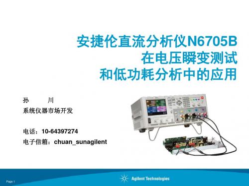
模拟常见情况下保险丝熔断时,对周围电路供电的影响
可能造成供电中断、故障的原因 #2
短路
为防止短路造成的电源系统故障,熔断保险丝或断路器被应用于每条供电 线路中,以防止过大电流的出现。但熔断器在熔断过程中会造成电压的瞬 间跌落,形成负电压脉冲,对周围的其他用电设备产生供电中断影响
安捷伦直流分析仪N6705B 在电压瞬变测试
和低功耗分析中的应用
孙
川
系统仪器市场开发
电话:10-64397274 电子信箱:chuan_sunagilent
Page 1
新平台:N6700 模块化电源系统 Award Winning Flagship Family Since 2019
N6700 Low-Profile MPS Mainframe
-Wireless platform/semiconductor developer May 2019
安捷伦独特的解决方案
N6705A 直流分析仪
单台仪器中整合多种测试仪器的功能, 为研发工程师大幅度提 高工作效率
•1 至 4 路高性能电源输出
•数字电压表和电流表
•带功率输出的任意波形发生 器
•示波器
-Defense contractor developing radio systems
“Makes a perfect power measurement system for FB-DIMM modules”
-Major semiconductor device manufacturer
“After you start using it, you can’t work without it anymore.”
安捷伦示波器探头

安捷伦示波器探头为获得示波器的最高使用效能,您应按特定的应用需要选用恰当的探头和附件。
这正是安捷伦公司为5000、6000 和7000 系列InfiniiVision示波器提供创新的全系列探头和附件的原因。
如欲了解有关安捷伦附件最新和最全面的信息,请访问我们的网站: http://.cn/find/scope_probesAgilent 5000InfiniiVision 示波器探头与附件、6000 和7000 系列选型指南技术资料目录探头兼容性表 (2)无源探头................................................................................................................................ .. 3高压无源探头......................................................................................................................... 5InfiniiMax 有源探头和附件 ................................................................................................. 6高压差分有源探头............................................................................................................... 8单端有源探头.. (10)混合信号示波器逻辑探头................................................................................................. 14电流探头................................................................................................................................. 16楔形探头适配器................................................................................................................... 18PC 连通性................................................................................................................................19Agilent IntuiLink 软件...................................................................................................... 19其他附件........................................................................................................................... 20测试车............................................................................................................................... 20仪器箱............................................................................................................................... 20机架安装套件 ................................................................................................................. 19探头定位器...................................................................................................................... 21安捷伦优势服务............................................................................................................. 封底安捷伦联系方式 ............................................................................................................. 封底探头兼容性表如欲得到更换探头或探头附件的订货信息: 请按照您的探头型号直接到表中列出的页数查看详细内容。
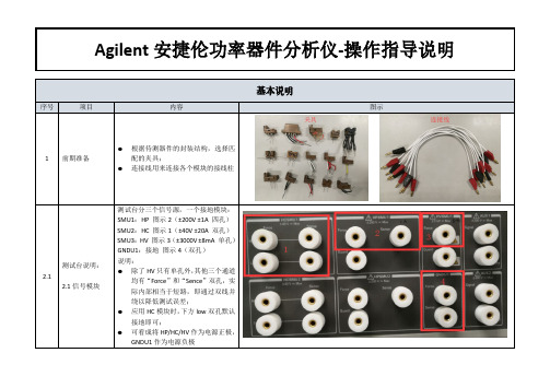
Agilent安捷伦功率器件分析仪-操作指导说明
Scale:选择曲线显示格式
Anode:二极管正极接电流源(依据
规格书测试条件合理选择,大于 1A
VF 测试-方法二
则需要选择 HC 通道) VfStart:开始电压
3.2 3.2 参数设置
VfStop:结束电压 VfStep:每个测试点电压间隔值
均有“Force”和“Sence”双孔,实 际内部相当于短路,即通过双线并 绕以降低测试误差; 应用 HC 模块时,下方 low 双孔默认 接地即可; 可看成将 HP/HC/HV 作为电源正极, GNDU1 作为电源负极
Agilent 安捷伦功率器件分析仪-操作指导说明
测试台说明: 2.2
2.2 接线模块
2.3 数据读取
▷ 点击“ ”启动测试;
完成测试后点击自动刻度; List Display 下拉数据,可以查看每个
Vr 下的反向漏电流 Ir,一般 Ir=250μA 时对应的最小 Vr 作为击穿电压
Agilent 安捷伦功率器件分析仪-操作指导说明
VF 测试 3.1
3.1 连线
按测试电路原理图,正确连接各接线柱。
IfSpec@Vf:自动读取所设正向电流
下对应的正向压降
Agilent 安捷伦功率器件分析仪-操作指导说明
▷ 点击“ ”启动测试;
完成测试后点击自动刻度;
VF 测试-方法一 List Display 下拉数据,可以查看每个
3.3
If 下的正向压降 Vf
3.3 数据读取
Agilent 安捷伦功率器件分析仪-操作指导说明
依 次 从 Application Test 选 择 PowerDiode,再选择 Ir-Vr 测试模块:
VR/IR 测试 2.2
安捷伦7000系列示波器中文技术资料

23···分段存储器DSO/MSO 离线分析电源管理 硬件加速的串行解码I 2C 、SPI CAN/LIN ··矢量信号分析内核辅助FPGA 调试安全环境RS-232/UARTFlexRay ·····4您的设计中有模拟、数字和串行信号…示波器是否也应该能够处理这些信号呢?MegaZoom III 技术。
MegaZoom III 深存储器可捕获长时间内不重复的信号,并保持高采样率,可快速放大您关注的区域。
采样率和存储器深度联系紧密。
示波器的深存储器可在长时间内保持高采样率。
快速发现偶发错误。
硬件加速解码增加了捕获到疑难事件的概率。
在间歇性故障遭到客户抱怨或关系到产品质量之前,安捷伦示波器可帮助您捕获到这些问题。
混合信号触发器。
可同时触发任意组合的模拟和数字信号。
一台仪器中包含精确的模拟测量和准确的数字内容,且它们之间有时间关联。
数字通道的应用。
使用Altera 或XilinxFPGA 进行设计?使用FPGA 动态探头进行快速的内部FPGA 测量。
使用I2C 、SPI 或RS-232?使用4通道型号的模拟或数字信号来采集和解码这些串行总线。
InfiniiVision 7000系列示波器通道可更快地确定疑难问题。
创新的高分辨率显示。
InfiniiVision 7000系列示波器具有XGA显示和256级的亮度,可精确表述您正在测试的信号的模拟特征。
配备有业内最快速的更新速率,可达100000波形/秒,您可捕获关键的信号细节,察看偶发事件,而这些在传统的示波器上可能被漏掉。
模拟信号:高达1 GHz 带宽和4 GSa/s采样率数字信号:具有混合信号触发的16位定时通道捕获模拟或数字的混合信号。
比较数字信号的多个周期和较慢的模拟信号。
具有高达2 GSa/s 深存储器的16位高速定时通道。
使用定时通道来评测控制信号关系。
安捷伦--N6705低功耗分析中的应用
产品耗电测试从未如此简单安捷伦直流分析仪N6705B在低功耗分析中的应用孙川系统仪器市场开发 电话:10-64397274 电子信箱:chuan_sun@Page 1新平台:N6700 模块化电源系统 Award Winning Flagship Family Since 2004N6700 Low-Profile MPS Mainframe Intro: Jan 2004N6700 DC Power Modules (26 models)N6705 DC Power Analyzer Mainframe Intro: May 2007"The small size and modularity of the N6700 are just what we need.“-Defense contractor developing radio systems“After you start using it, you can’t work without it anymore.”-Wireless platform/semiconductor developer May 2010“Makes a perfect power measurement system for FB-DIMM modules”-Major semiconductor device manufacturer新平台:N6700 模块化电源系统 Award Winning Flagship Family Since 2004Page 3安捷伦独特的解决方案N6705A 直流分析仪单台仪器中整合多种测试仪器的功能, 为研发工程师大幅度提 高工作效率• 1 至 4 路高性能电源输出 • 数字电压表和电流表 • 带功率输出的任意波形发生器 • 示波器 • 数据采集 • 所有的测量和功能都能通过前面板实 现短时间内快速详细的掌握在各种情况下DUT的工作情况 而不需要写一行代码!议程1. N6705B简介和回顾 2. N6781/82A源表模块在低功耗分析 中的应用 3. N6781/82A作为电子负载在电源芯 片测试中的应用 4. 安捷伦太阳能测试方案Page 5N6705B的典型应用:仿真供电中断、故障现象1. 供电系统内部电源的切换过程• • • •2.地面供电 切换至内部供电 运行过程中,内部供电电源之间的切换,如多个直流发电机之间的切换 特殊情况:内部电源 切换至 备份电源,如卫星进入阴影区域,或者航 天器主发电机产生故障 由电源切换所造成的供电中断时间应小于50ms短路造成电压跌落和供电中断,造成短路的原因: • 绝缘损坏,连线故障,战斗损伤等 • 短路保护主要由熔断器来实现短路现象3.抛负载现象• •• 其他干扰现象负载突变(如电池与发电机的连接脱落)会导致输出 电压产生巨大波动WWFO Decision可能造成供电中断、故障的原因 #1供电电源之间的切换供电电源间的切换导致电压波动甚至中断,这种电源波动会对机载设备 产生影响,导致电子产品非正常关机,死机或进入错误工作状态电池供电切换至发电机供电时,典型的电压跌落、摆动波形模拟常见情况下保险丝熔断时,对周围电路供电的影响可能造成供电中断、故障的原因 #2短路为防止短路造成的电源系统故障,熔断保险丝或断路器被应用于每条供电 线路中,以防止过大电流的出现。
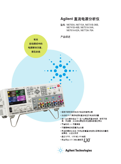
N6705A 直流电源分析仪
7
其它特性
可设置电压变化率
提高测量精度的 4 线远端感应
图10. Output On/Off Delays 屏幕允许您送 入各输出的延迟时间。设置的图形显示确 认您的选择无误。
6
大功率任意波形发生器
Agilent N6705A 直流电源分析 仪中的各直流电源模块都有内置的 任意波形发生器调制功能。因此可 把该直流输出当作直流偏置瞬态发 生器,或是大功率任意波形功率发 生器。最大带宽由模块的类型确 定。见 21 页表中列出的各种直流 电源模块类型的带宽。
Agilent N6705A 使用运行长度 编码,波形中的每一点由电压设置 和停留时间或逗留于该设置的持续 时间定义。可通过只规定少量的点 数产生波形。例如只需3 个点就可 定义脉冲。
隔,它可设置为 75ms 至 60s。对 于每路直流输出,数据记录仪可 同时或分别记录电压测量和电流 测量结果。所有直流模块类型都 可使用标准模式数据记录。
• 连续采样模式: 直流电源模块中的 内置数字化仪以 50kSa/s 读出速 率连续运行。您可规定采样周期, 即要累积连续读数的时间周期。 每一采样周期将保存一个平均读 数(也可选最小值和最大值)。在 该模式时,数字化仪连续运行,
对于用户定义的电压和电流波 形,您可下载多达 512 个电压或电 流设置点。为各设置点规定停留时 间,输出将在该设置点保持(或停 留)所编程的停留时间值。对于用 户定义波形中 512 个设置点的每一 设置点,您可有分辨率为 1μs,从 0s 至 262s 的不同停留时间*。模块 将按用户定义的量值表步进,在各 设置点停留设置的停留时间,然后 移到下一设置点。用户定义波形可 从 CSV 文件输入,或直接从直流 电源分析仪的前面板送入。
Voltech PM6000电源分析仪说明书

V oltech PM6000Power AnalyzerA New Standard in Power AnalysisThe Voltech PM6000 Power Analyzer• Up to 6 wattmeter channels• 0.02% basic accuracy for definitive power loss and efficiency measurements • Sampling at 40MHz (5MHz minimum) for error-free results• Outstanding rejection of common-mode signals for accuracy in all applications • A bright color display and intuitive menu system for ease of use • Connectivity: RS232, Printer, Ethernet, USB* (*Future Release)New generation power analyzer PM6000 has the power to provide:Versatile, accurate, fully-featuredand yet easy-to-useThe PM6000 provides definitive measurements of all electrical power quantities on all products that consume, convert or generate electrical power. The Voltech PM6000 combines years of power measurement know-how with the latest digital signal processing technology to provide a unique combination of measurement and reporting features that will solve power measurement problems.Why the PM6000? There is a constant consumer and legislative pressure to design electrical products that are more efficient, power electronics designers use more and more sophisticated control methods and increases in switching frequency to achieve this. Therefore more sophisticated, more accurate and higher bandwidth power measurements are required to validate and test power electronic designs.The PM6000 has been designed especially to meet the needs of today’s design and test engineers by providing greater flexibility and bandwidth at high accuracy.The PM6000 is an advanced digital sampling power analyzer. From 1 to 6 measurement channels may be fitted to a PM6000. Each measuring channel is a separate wattmeter with fully floating inputs for connection to the voltage and current of the power circuit to be measured.Voltages up to 2000 Vpk may be connected directly to the measurements channels and a wide variety of current transducers may be used, including wide-bandwidth resistive current shunts from Voltech. The Voltech shunts plug directly into the measurement channel for convenience, and have the advantage that the shunt’s calibration data is automatically transferred to the PM6000, providing optimum accuracy for the complete measurement path. For other external current transducers, each channel can supply ±12V DC power. Unique and proprietary algorithms are then used to process the samples and provide stable and accurate measurements in all applications.MeasurementsFront PanelThe intuitive menu system will guide you through the set-up and control of the analyzer. Working through the options step-by-step allows you to configure channels into groups for a variety of multi-phase connections, to set scaling for external voltage and current transducers, and to choose the required measurements.Rear PanelAt the rear, comprehensive control is provided via RS232. Standard printers may be connected directly for local print-out of numeric results.The ethernet port allows for powerful control and datalogging to a network drive.Set-Up and Controlcontrolfunction keysAdvantages• U p to six channels configurable as required, for example AC input plus 5 DC outputs or three-phase input and output.• Excellent 0.02% basic accuracy - useful for high efficiency measurements.• Accurate on all waveforms.• Samples continuously, without gaps at 5 MSPS so there is no missing dataduring integration or low-power standby measurements.Power transformers are characterized under open-circuit and short-circuit conditions. Open-circuit, the power factor of the transformer is closeto zero (<0.01), which demands very low phase error, from the power analyzer.The analog design of the PM6000 ensures that its voltage and current channels are carefully matched, providing optimum performance at low power factors.Applications - Power TransformersAdvantages• Up to six channels for simultaneous three-phase input and output – Star (Wye) or Delta connection.• Accurate at low power factors. (<0.01)• Simultaneous measurement of rms and mean voltage as required by IEC76 and IEEEC57.• Measure turns ratio directly using the math function.MeasurementsWatts, Vrms, Vrmn, Arms, VA, VAr, Apk, Harmonics, THD, Inrush.K-factor and corrected power to IEEE and IEC standards.Applications – Variable Frequency Drivesand MachinesThe versatile PM6000 will make simultaneous measurements at the input and output of a drive, allowing accurate efficiency measurements under all load and speed conditions.Advantages• Up to six channels configurable as required, for example 3 wattmeter, three- phase input, DC bus and two-wattmeter drive output and torque and speed measured simultaneously.• Excellent 0.02% basic accuracy - useful for high efficiency measurements.• 10MHz bandwidth captures all motor frequency and high-frequency data for the most accurate overall power measurement.• High rejection of common-mode signals found on the drive output. 140dB @ 60Hz, 95dB@1MhzMeasurementsApplications - Power Integration / StandbyThe power consumption of everyday home and office electrical appliances is of importance to consumers and generators of electricity alike.When the power consumption varies over time, then integration of the power ( W-h integration) is required. The PM6000 provides comprehensive integration features suitable for Energy Star measurements and for low-power measurements in accordance with international directives, eg. IEC 62301 which also requires crest factor measurements up to 8 and 50 harmonics.Advantages• Excellent 0.02% basic accuracy - useful for high efficiency measurements.• Accurate on all waveforms.• Samples continuously, without gaps at 5 MSPS so there is no missingdata during integration or low-power standby measurements.• Versatile current channel input for low – current measurements. 1A Voltech plug-in shunt available.MeasurementsIEC 62301Voltech continues to be a leader in producing power analyzers that meet the ever changing needs of today’s world. A mandatory measurement for products in Europe and many other countries, the IEC standards definespecific methods for testing current harmonics and flickerApplications - IEC Harmonics and FlickerAdvantages.• F ull compliance testing for EMC laboratories when used with an AC Source and Impedance Network.• S uperb pre-compliance measurements when used stand-alone.• P C software plays back previous tests and generates reports suitable for technical construction files.• D iscrete Fourier Transform (DFT) ‘reference instrument’ implementation avoids the problems of Fast Fourier Transform (FFT) analyzers.• S olutions for harmonics and flicker to 75A.(voltage changes). The PM6000 and its easy-to-use software provide design engineers and EMC test laboratories with a comprehensive suite of measurements and reports that fully comply with the latest standards.To measure the efficiency of a high-frequency ballast, its essential tohave an accurate measurement of both the input and output power of the ballast. With unbeatable accuracy at both low and high frequencies, and superior common-mode rejection, the PM6000 will make the most accurate efficiency measurements possible.Applications - Lighting BallastsPurposely designed for lighting applications, this device overcomes problems that are usually found when using conventional or Hall effect CTs.• Convenient: No need to feed cables through a CT core. • Better than 1% accuracy: Trifilar wound toroidal core.• 5kHz to 1MHz bandwidth . • 5mA to 1A measurement rangeAccessoriesPM6000 Back Panel with 6 channels and 3 Voltech 30A shunts fitted.• Accuracy better than 1%• Connect to the PM6000 via safety leads and 1A shunt • CL100 100A:1A • CL1000 1000A:1A• Accuracy (23°C ± 5°C): ± 0.2% of specified ratio • Frequency range: 45Hz to 1kHz• Current range: 100:1 ratio: 10A to 120A rms 1000:1 ratio: 100A to 1200A rms• Maximum input current: 1000A continuous 2000A for 1 hour • Phase error (23°C ± 5°C): Better than ± 0.1° at 50HzSolid-state switch for energizing loads (up to 200Apk) at either the peak or the zero crossing of AC voltage. Ideal for inrush current testing.Clamp-on Current TransformersCT1000 –Dual Ratio Precision Current TransformerPS1000 - Inrush SwitchBallast CTPM6000 ChassisWith color VGA display and 3½” floppy drive. Connectivity: RS232, Printer, Ethernet, USB*(*Future Release)Hard Disk Drive (Optional)PM6000 Measurement ChannelHigh performance wattmeter channel. Voltage 1500V , Current 2.5V for shunt or current transducer. ±12V DC supply for external current transducer.OrderingVoltageCurrentPower1. At 23ºC ± 5ºC, valid 1 year from calibration.2. %rdg = percentage of reading, % rng = percentage of range, F = frequency in kHz.3. Vrng = Voltage range: 5, 10, 20, 50, 100, 200, 500, 1000, 2000Vpk.4. Irng = Current range.30A shunt: 0.5, 1, 2.5, 5, 10, 20, 50, 100, 250Apk.1A shunt: 0.01, 0.02, 0.05, 0.1, 0.2, 0.5, 1.0, 2.0, 5.0Apk.Voltage input: 0.005, 0.010, 0.025, 0.05, 0.10, 0.25, 0.50, 1.0, 2.5Vpk.1A Shunt1A rms, 5Apk precision measuring shunt withcalibration stored in EEPROM. (Bandwidth 10MHz)30A shunt30A rms, 200Apk precision measuring shunt with calibration stored in EEPROM. (Bandwidth 1MHz)Lead set2 pairs (yellow and black) 1.5m, 2000V , 30A leads with safety connectors and alligator clips.Magnitude(V)=0.02%rdg +0.05%rng +(0.001%x F )rdg +20mVPhase (º)=0.005+ 0.0003x + +(0.001xF)][V rng V 0.05VMagnitude(A)=0.02%rdg +0.05%rng +(0.001%x F )rdg +20uVZ EXTPhase (º)=0.0025+ 0.0005x + +(0.0006x F)][I rng I0.00004IxZ EXT Specifications5. Ø = angle between voltage and current.6. Zext = 0.01 (30A shunt), 0.5 (1A shunt), 0.0125 (default voltage input) ohms.Voltech Instruments Inc.11637 Kelly Road, Suite 306Fort Myers, FL 33908USATel: (239) 437 0494Fax: (239) 437 3841**********************Voltech has an intensive program of design and development andreserves the right to alter product specification without notice. Although every care has been taken in compiling this information Voltech does not accept any liability for errors or omissions. ©2006 Voltech.Voltech Instruments Ltd.148 Harwell Int’l Business Centre Didcot, Oxon. OX11 0RA UKTel: +44 (0) 1235 834555Fax: +44 (0) 1235 835016Email:****************.ukV oltechDistributorVPN: 86-506/9Error(Watts)= + + (tan 0x(Vh1Ph error+Ah1Ph error ) x ) x W [V RMS V RMS error A RMSA RMS error]180 π。
PowerLogic 电力参数测量仪 PM5350

报警介绍 ............................................................... 25 标准过/欠报警........................................................... 26
CT 数量设置............................................................ 16 VT 数量设置............................................................ 16 额定值设置 ............................................................ 16 仪表需量设置............................................................ 17 电能和电流需量设置 .................................................... 17 选择数字输入 .......................................................... 17 仪表高级设置............................................................ 17 设置标签 .............................................................. 17 设置负荷计时器设定点 .................................................. 17 设值上一年度峰值电流需量 .............................................. 17 仪表通讯设置............................................................ 17 设置通讯 .............................................................. 17 设置报警 .............................................................. 17 设置 I/O............................................................... 17
电源维护常用测量仪表介绍
电源维护常用测量仪表介绍电源设备的检测维护需要使用各类仪表对其参数进行周期性的测量,并要求对测试数据作出正确的分析判断,从而发现障碍隐患,分析故障源头,为供电设备的故障排除提供理论依据,保证供电网络的正常运行。
因此熟练掌握常用电源维护测量仪表是对电源维护人员最基本的要求。
本文主要介绍万用表、交直流钳形表、电力谐波分析仪、示波器、宽频杂音计、接地电阻测试仪、温湿度测试仪、声级计这9种常用电源维护仪表。
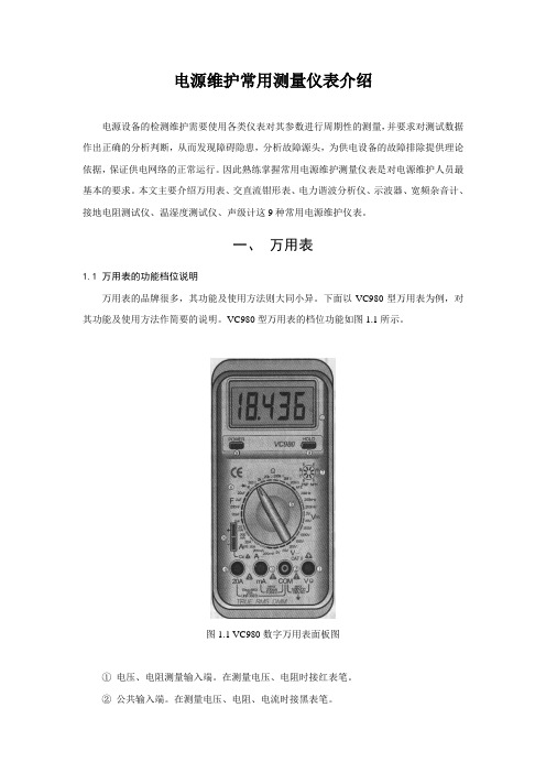
一、万用表1.1 万用表的功能档位说明万用表的品牌很多,其功能及使用方法则大同小异。
下面以VC980型万用表为例,对其功能及使用方法作简要的说明。
VC980型万用表的档位功能如图1.1所示。
图1.1 VC980数字万用表面板图①电压、电阻测量输入端。
在测量电压、电阻时接红表笔。
②公共输入端。
在测量电压、电阻、电流时接黑表笔。
③电流测试输入端。
测量电流时接红表笔,最大输入电流为200mA 。
④电流测试输入端。
测量电流时接红表笔,最大输入电流为20A 。
⑤功能档位转盘。
用于选择不同的测量功能和档位。
⑥档位及量程选择。
V ~:交流电压测量档,分为200mV、2V、20V、200V、700V 5 档V:直流电压测量档,分为200mV、2V、20V、200V、1000V 5 档。
A ~:交流电流测量档,分为200mA、20A 2 档。
A:直流电流测量档,分为20mA、200mA、20A 3 档。
Ω:电阻测量档,分为200Ω、2kΩ、20kΩ、200kΩ、2MΩ、20MΩ 6 档:通断及二极管测量档。
Hz :频率测量功能档。
分为20kHz、200kHz 两档。
hFE:三极管放大倍数测量档。
F :电容测量档。
分为2nF、20 nF、200 nF、2μF、20μF共5 档。
许多高级的数字式万用表采用了自动量程,取消了复杂的量程档位,简化了测量操作。
⑦三极管测试插孔。
分为PNP 和NPN 两种不同形式的插孔。
⑧电容测试输入插孔。
N6705C 直流电源分析仪
5
136 138 143 144 145 145 146 147 147 150 154 156 157 159 159 160 160 162 164 164 165 165 166 167 167 167
169
170 170 171 172 172 173 174 176 177 179 179 180 180 181 182 182 183 183 183 184
认证
是德科技保证本产品出厂时符合其发布的技术指标。是德科技进一步保证其校准测量遵循美 国国家标准和技术研究院的规定,并符合该研究院及其他国际标准组织成员制定的校准设备 规范。
7
Keysight N6705C 用 户 指 南
法律和安全信息
美国政府的权利
本 软 件 为 符 合 联 邦 政 府 采 购 法 规 ("FAR") 2.101 规 定 的 “商 用 计 算 机 软 件 ”。 按 照 FAR 12.212 和 27.405-3 以 及 国 防 部 FAR 补 充 条 款 ("DFARS") 227.7202, 美 国 政 府 根 据 向 公 众 提 供 商 用 计 算 机 软 件 的 一 般 条 款 采 购 本 软 件 。 相 应 地 , 是 德 科 技 依 据 其 最 终 用 户 许 可 协 议 (EULA) 中 所 述 的 标 准 商 业 使 用 许 可 向 美 国政府客户提供本软件,您可以从以下网址获取该许可协议的副本: /find/sweula。 EULA 中 所 述 的 许 可 表 示 美 国 政 府 使 用 、 修 改 、 分 发 或 披 露 本 软 件 所 具 有 的 专 属 权 利 。 除 了 其 他 事 项 之 外 , EULA 及 其 中 规 定 的 许 可 不 要 求 或 不 允 许 是 德 科 技 : (1) 提 供 通 常 不 会 向 公 众 提 供 的 与 商 用 计 算 机 软 件 或 商 用 计 算 机 软 件 文 档 相 关 的 技 术 信 息 ; 或 者 (2) 让 与或以其他方式提供的政府权利超过通常向公众提供的与使用、修改、复制、发布、执行、显示 或 披 露 商 用 计 算 机 软 件 或 商 用 计 算 机 软 件 文 档 有 关 的 权 利 。 EULA 中 未 涉 及 的 其 他 政 府 要 求 不 适 用 , 除 非 按 照 FAR 和 DFARS 的 规 定 明 确 要 求 所 有 商 用 计 算 机 软 件 提 供 商 提 供 这 些 条 款 、 权 利 或 许 可 证 , 并 且 EULA 中 的 其 他 地 方 有 专 门 的 书 面 说 明 。 是 德 科 技 对 更 新 、 修 订 或 以 任 何 其 他 方 式 修 改 本 软 件 不 承 担 任 何 责 任 。 对 于 FAR 2.101 定 义 的 任 何 技 术 数 据 , 根 据 FAR 第 12.211 条 和 第 27.404.2 条 以 及 DFARS 第 227.7102 条 的 规 定 , 美 国 政 府 所 获 得 的 权 利 不 会 超 出 FAR 第 27.401 条 或 DFAR 第 227.7103-5 (c) 条 所 定 义 的 适 用 于 任 何 技 术 数 据 的 “有 限 权 利 ”。
国家仪器 9755 CompactRIO NOx 传感器模块套件用户手册说明书

USER MANUALNI 9755NI Powertrain Controls CompactRIO NOx Sensor Module KitContents Introduction (1)System Diagram (2)Hardware (2)Powering the Hardware (3)Wiring Harness (5)IntroductionThe National Instruments 9755 CompactRIO NOx Sensor Module Kit interfaces with NO x and O2 exhaust gas sensors.Features•Configurable from one to four channels•Measures NO x (ppm) and O2 (%) concentrations•Sensor controller supply voltage of 12 V to 16 V (24 V version available)•Reverse battery protection on sensor controller module•Sensor controller module harness•LabVIEW FPGA and RT VIs for quick integration with application•Integration with existing PXI or CompactRIO chassis hardware2| |NI 9755 User Manual System DiagramFigure 1. NI 9755 SystemHardwareThe NI 9755 includes the following hardware:•Continental UniNOx Smart NOx Sensor with integrated sensor controller module •Sensor bung •Wiring harness •NI-9853 CompactRIO High-Speed CAN moduleThe wiring harness in the NI 9755 connects to the NOx Sensor Control Module and splits into two cables for the NI-9853 module and an external power supply. The first cable connects to the NI-9853 with a female DB-9 connector. A terminating resistor of approximately 120 Ω is located inside this cable near the NOx Sensor Control Module and between the CAN High and CAN Low wires. The second cable provides three non-terminated leads for connecting to a power supply, which requires two leads, and for address selection of the NOx Sensor Module, which requires one lead. If the cable is to be extended, follow CAN network wiring guidelines.Refer to the NI 9853 CAN Module Operating Instructions and Specifications for more information on cabling requirements.NoteYou must use the sensor included in the NI 9755 kit. NI does not support other sensors.Powering the HardwareThe NI 9755 requires power from a range of 12 V to 16 V with a continuous current of 1.5 A and a peak current of 16 A. The maximum power requirement is20W, which typically occurs when the heating element is being turned on from a cold state. If you are using two sensors, double the capacity of the power supply.Refer to the NI 9853 Operating Instructions and Specifications for more information on power requirements.Contact National Instruments for more information about sensor specifications.NOx Sensor Light-Off TimesConditionsAir T.........................................................25 ±5 °CBatt V........................................................14 VHeater........................................................ONNO x...................................................................< 100 sO2......................................................................< 80 sNOx Sensor Preheating FunctionWhen power is supplied to the sensor, the sensor enters preheating mode automatically until the Sensor Enable Boolean is set to TRUE within the supporting software. The Sensor Enable Boolean turns the internal sensor heater to its ON state. If the Sensor Enable Boolean is set to FALSE, the sensor returns to preheating mode. The preheating mode protects the sensor from mechanical cracks caused by water splash.NOx Sensor Operating Temperature RangesSensor module controller temperature..............-40 °C to 105 °C(105 °C to 115 °C for a maximum of 10 minutes) Storage temperature range................................-40 °C to 120 °CMaximum storage time.....................................2 yearsMaximum exhaust gas temperature..................800 °C (950 °C for a maximum of 100 hours) Maximum sensor hexagon screw temperature...620 °C (650 °C for a maximum of 100 hours) Maximum sensor grommet temperature...........200 °C (230 °C for a maximum of 100 hours) Preheating sensor temperature..........................80 °C to 120 °CLifespan approved by life cycle pattern...........2,000 hours or 120 K milesNI 9755 User Manual|© National Instruments|3NOx Sensor Electrical Characteristics NOx Sensor Supply VoltageMinimum supply voltage..................................12 VMaximum supply voltage.................................16 VNOx Sensor Supply CurrentAverage supply current.....................................1.5 APeak supply current at switch on......................16 ASupply PowerMaximum supply power...................................20 WNOx Sensor MiscellaneousThread Torque...................................................50 N · m (36.88 lb · ft) Lubrication........................................................Anti-seize compoundFigure 2. Installation PositionFigure 3. Tilt Angle in Gas Flow Direction4||NI 9755 User ManualNOx Sensor Controller Module ConnectorType of connector.............................................Hirschmann MLK 872-860-501Number of pins (5)Connector pin assignmentPin 1..........................................................Battery [red]Pin 2..........................................................Ground [black]Pin 3..........................................................CAN Low [blue]Pin 4..........................................................CAN High [orange]Pin 5..........................................................Address Switch [purple]Pulling Pin 5 to ground changes the CAN transmit ID of the NOx sensor control module so that two NOx sensor control modules can be added to the same network. Sensor Control Modules with Pin 5 floating are Ch. 1 and Sensor Control Modules with Pin 5 grounded are Ch. 2. Wiring HarnessFigure 4. 2-Sensor Harness1 Batt and GND wires manufactured in 2018 or earlier use 18 AWG wires.Refer to the NI Trademarks and Logo Guidelines at /trademarks for more information on National Instruments trademarks. Other product and company names mentioned herein are trademarks or trade names of their respective companies. For patents covering National Instruments products/technology, refer to the appropriate location: Help»Patents in your software, the patents.txt file on your media, or the National Instruments Patents Notice at /patents. You can find information about end-user license agreements (EULAs) and third-party legal notices in the readme file for your NI product. Refer to the Export Compliance Information at/legal/export-compliance for the National Instruments global trade compliance policy and how to obtain relevant HTS© 2013–2019 National Instruments. All rights reserved.376104B-01Apr19。
- 1、下载文档前请自行甄别文档内容的完整性,平台不提供额外的编辑、内容补充、找答案等附加服务。
- 2、"仅部分预览"的文档,不可在线预览部分如存在完整性等问题,可反馈申请退款(可完整预览的文档不适用该条件!)。
- 3、如文档侵犯您的权益,请联系客服反馈,我们会尽快为您处理(人工客服工作时间:9:00-18:30)。
众所周知,智能穿戴产品的续航功耗是非常低的,基本上都是uA级别的电流功耗,所以在产品研发设计中都会使用低功耗测试仪器来进行辅助测试和算法调试,已达到功耗最优,续航最佳的状态。
智能硬件大公司的实验室基本上都会配有Keysight N6705直流电源分析仪来进行低功耗的测试评估,由于其昂贵程度,有一些中小型的公司则会使用性价也比较高的测试仪器进行测试评估,比如Egteks mPower1203仪器。
所以,今天我们针对同一款智能穿戴产品的功耗评估数据,来比较一下Egteks mPower1203仪器和KEYSIGHT N6705仪器的测试数据差异如何。
简单介绍两种仪器:
Egteks mPower1203设备是一款集便携式直流供电、高精度电流测试、动态电流波形显示分析以及高性价比为一体的直流分析电源,配合自带的软件工具,可实现待测产品/电路的动态功耗测试评估及分析,同时小尺寸的身材具有非常好的便携优势。
Keysight N6705直流电源分析仪是低功耗评估设备中知名度最高的一款测试设备。
当然其价格也是前者的几十倍,它具有非常丰富的功能,将多达4个先进电源与数字万用表、示波器、任意波形发生器和数据记录仪功能融为一体,可以显著提高为被测器件提供和测量直流电压和电流的效率。
动态低功耗测试评估:
使用KEYSIGHT N6705仪器测试一款智能穿戴设备的电流波形,同时使用Egteks mPower1203的电源功能和电流表功能下的Auto模式和Precision模式分别进行相同测试操作。
1.如下图所示,获得两种仪器测试结果,得出穿戴设备的两种状态下的动态功耗(状态1:IDLE;状态2:SLEEP)。
2.将Egteks mPower1203测试值与N6705仪器测试值进行对比,查看两者的测试差异。
测试现场图:
测试数据对比:
IDLE SLEEP 图示
KEYSIGHT
93.71uA 57.424uA 4-1/4-2
N6705 Test1
KEYSIGHT
94.68uA 57.694uA 4-3/4-4
N6705 Test2
KEYSIGHT
91.706uA 57.141uA 4-5/4-6
N6705 Test3
Egteks mPower1203
95.145uA 58.896uA 4-7/4-8
电源功能/Auto
Egteks mPower1203
95.054uA 59.074uA 4-9/4-10
电源功能/Precision
Egteks mPower1203
94.933uA 60.578uA 4-11/4-12
电流表功能/Auto
Egteks mPower1203
94.625uA55.650uA 4-13/4-14
电流表功能/Precision
从数据对比中可以看出:
1.KEYSIGHT N6705仪器的3次测试数据中,由于测量的是动态电流,所以相互之间也会存在一些差异。
2.Egteks mPower1203的电源功能和电流表功能下的动态电流测试数据,与KEYSIGHT N6705仪器的测试数据非常接近,平均相差值在2uA左右。
动态电流测试波形图示:
使用KEYSIGHT N6705仪器对测试3次,获得3组测试数据:Test1 Figure4-1 Test1 Figure4-2
Test2 Figure4-3 Test2 Figure4-4
Test3 Figure4-5Test3 Figure4-6
使用Egteks mPower1203电源功能对设备进行供电及电流测试:Auto模式Figure4-7Auto模式Figure4-8
Precision模式Figure4-9Precision模式Figure4-10
使用Egteks mPower1203电流表功能对设备进行电流测试:Auto模式Figure4-11Auto模式Figure4-12
Precision模式Figure4-13Precision模式Figure4-14
为了进一步验证Egteks mPower1203的测试精度,我们使用100kΩ、10kΩ以及1kΩ的电阻负载来验证其真实的电流精度。
将mPower1203设置成电源功能,分别输出0.6V/1V的电压,加载在三种不同的电阻负载上,测试流过的电流,该为下表中的实测电流。
由于电阻和输出电压都有误差存在,所以我们使用福禄克万用表(Fluke 18B+)串入测量出实际电流,对比实测电流和实际电流就可以得出相对的精度。
对于uA级别的电流,mPower1203规格书中提到的是±0.5%±2uA,可以得出表中的数据是和规格书描述一致的。
电源功能预设电流电阻负载mPower1203
输出电压
实际电流
mPower1203
实测电流(Avg)
精度图示
Precision
6uA 100kΩ0.601V 6uA 5.976uA 0.5% 1 100uA 10kΩ 1.002V 100.2uA 100.5uA 0.29% 2 1mA 1kΩ 1.003V 1.002mA 1.001mA 0.1% 3
Auto
6uA100kΩ0.602V6uA 5.989uA 0.5% 4 100uA10kΩ 1.001V 100.1uA 100.4uA 0.3% 5
1mA1kΩ 1.001V0.998uA 0.994uA 0.4% 6 Precision-1Precision-2Precision-3
Auto-4Auto-5Auto-6
从对比数据来看,Egteks mPower1203的精度和采样率都能满足大部分低功耗设备以及智能穿戴设备的应用,对于研发经费有限的中小型企业来说,是个非常不错的选择。
