T+安装手册
精密机房空调中文雷纳多安装手册T系列

R407C ....................................................................... 21
R410A ....................................................................... 22 回液管直径 (LIQUID) .................................... 25 建议搭配的室外机 .......................................... 25
雷纳多直接膨胀式机组 .................................................. 10 技术参数 .................................................................. 10 操作说明 .................................................................. 11 主要零件名称及描述 .............................................. 12 交货检查 .................................................................. 15 卸载机器 .................................................................. 15 安装方面要求 .......................................................... 15 安装机组 .................................................................. 16 安装在高架地板上 .......................................... 16 直接安装在地面上 .......................................... 16 安装底座上(Floor stand) ........................ 16 开启与拆卸面板 ...................................................... 16 开门 .................................................................. 16 拆卸前面板和侧面板 ...................................... 16 拆卸后面板 ...................................................... 17 内部保护挡板 .................................................. 17 电气连接 .................................................................. 18 排水管连接 ...................................................... 19 连接安全阀排气管 .................................................. 19 与室外机的连接 ...................................................... 20 选择排气管尺寸 ...................................................... 20
S450 L25塔式起重机使用说明书及安装手册.

S450 L25 塔 式 起 重 机 使 用 说 明 书 ——安 装 手 册沈阳三洋建筑机械有限公司目 录整机外形及起重特性………………………………………………………… P5第一部分:场地准备………………………………………………………… P61.起重机性能、占地面积、部件重量……………………………………… P7 1.1整机布置图及主要尺寸…………………………………………… P71.2钢筋混凝土支脚图……………………………………………………… P81.3主要杆件和销轴规格…………………………………………………… P9-10 1.4空间要求和重量………………………………………………………… P11 1.5要组件的重量及起升高度汇总表……………………………………… P12-201.6吊臂、平衡重心位置…………………………………………………… P212.轨道………………………………………………………………………… P22 2.1轨道的选择……………………………………………………………… P22 2.2轨道的铺设……………………………………………………………… P22 2.3轨距和弯半径…………………………………………………………… P23 2.4混凝土轨枕轨道………………………………………………………… P24-27 2.5木枕轨道………………………………………………………………… P282.6轨道停止器…………………………………………………………… P29-303.固定支脚的混凝土块……………………………………………………… P31 3.1准备条件………………………………………………………………… P31 3.2力和反力………………………………………………………………… P32 3.3地面承压力和混凝土块的选择………………………………………… P33-34 3.4固定支脚的尺寸特性…………………………………………………… P353.5固定支脚的安装………………………………………………………… P36-384.电源安装…………………………………………………………………… P39 4.1引言……………………………………………………………………… P39 4.2电缆卷筒功率…………………………………………………………… P39 4.3电缆卷筒………………………………………………………………… P394.4接地……………………………………………………………………… P405.压重………………………………………………………………………… P415.2压重表…………………………………………………………………… P415.3压重块的参数………………………………………………………………P42-446.配重 …………………………………………………………………………P45 6.1说明…………………………………………………………………………P45 6.2配重表………………………………………………………………………P456.3配重图………………………………………………………………………P45-487.附着示意图…………………………………………………………………P49-50 第二部分:立塔…………………………………………………………………P511.一般安装说明………………………………………………………………P512.安装台车和横梁……………………………………………………………P52-553.安装基础塔身节……………………………………………………………P56-584.下十字梁的安装……………………………………………………………P595.内塔身安装…………………………………………………………………P59-606.回转机构及司机室(太空舱)的安装……………………………………P617.平衡臂安装…………………………………………………………………P61-628.撑架安装……………………………………………………………………P639.安装吊臂……………………………………………………………………P64-6710.配重的安装…………………………………………………………………P6811.吊臂和平衡臂的组装………………………………………………………P69-7012.起重小车和滑轮组的安装…………………………………………………P73-7913.塔身加节……………………………………………………………………P80-8314.标准节安装…………………………………………………………………P84-8515.顶升平衡……………………………………………………………………P86-8716.顶升…………………………………………………………………………P88-8917.风速仪的安装方法…………………………………………………………P9018.障碍警号标志灯安装方法…………………………………………………P91-9319.立塔后进行检查……………………………………………………………P9420.投入使用……………………………………………………………………P95第三部分:拆塔……………………………………………………………… P96S450 L25自升塔式起重机 GB/T13752-92 外形尺寸起重特性如果需要45m臂长及35m臂长组合时,请与供应商联系,需要特殊定制。
EC301-TS 安装手册-S200厅门系统(中文版)

Version: 1.0
编号:EC301-TS
tk
A Company of ThyssenKrupp
ThyssenKrupp Elevator
蒂森克虏伯电梯 Elevator
Installation Manual
编号:EC301-TS
警
告
电梯安装人员需是经当地劳动和社会保障局培训并取得上岗操作证的人员。在安装前需认真阅读 此安装手册。所有电梯零部件安装人员都必须严格遵守相关安全规范。电梯安装人员严格遵守此安装 手册将为电梯性能及使用者的安全提供最大保障。如果您未按本安装手册的要求操作及对本设备进行 修改或改装而引起的任何损失,蒂森克虏伯电梯公司将不承担责任。
编制 Edited by 审核 Checked by 标准化 Standardized by 批准 Approved by
蒂森克虏伯电梯(中国区制造)工程中心
ThyssenKrupp Elevators (Manufacturing China) Engineering Center
安装手册-S200 厅门系统
垫片 挂门螺栓组件
GB/T6177-1986 六角头法兰面螺母M8 GB/T6177-1986 六角头法兰面螺母M10
GB/T5783-2000 六角头螺栓M8×20
GB/T93-1987 标准弹簧垫圈8
GB/T95-1985 平垫圈8
图 4-6 厅门门板与滑块的安装
门滑块组件
ThyssenKrupp Elevator
M10
5
上、下位置调整
5
水平位置调整
门板与置的调整
ThyssenKrupp Elevator
tp-link安装手册

安装手册
企业级无线VPN路由器 TL-WVR450L TL-WVR458L TL-WVR900L TL-WVR1300L
声明
Copyright © 2016 普联技术有限公司 版权所有,保留所有权利
未经普联技术有限公司明确书面许可,任何单位或个人不得擅自仿制、复制、誊抄或 转译本手册部分或全部内容,且不得以营利为目的进行任何方式(电子、影印、录制 等)的传播。
RJ45端口
-"/
108&3
RJ45端口 水晶头
3&4&5
8"/
8"/-"/
-"/
108&3
图3-1
路由器连接线缆示意图
硬件连接
08
企业级无线VPN路由器安装手册
说明: ■■ 对于10Base-T以太网,建议使用3类或以上的UTP/STP线; ■■ 对于100Base-TX以太网,建议使用5类或以上UTP/STP线; ■■ 对于1000Base-T以太网,建议使用超5类UTP/STP线; ■■ 路由器以太网口自动翻转功能默认开启,采用5类双绞线连接以
1.1 产品简介...................................................... 01 1.2 产品外观...................................................... 01
第2章 安装准备—————————————— 04
本系列路由器目前具体包含型号如下:
产品型号 TL-WVR450L TL-WVR458L TL-WVR900L TL-WVR1300L
GSK988T安装调试手册 V2.03d.
附录一报警信息表(187
附1.1程序报警(P/S报警(187
附1.2参数报警(195
附1.3脉冲编码器报警(195
附1.4伺服报警(195
附1.5超程报警(196
附1.6主轴报警(196
附1.7系统报警(196
附1.8操作面板通信提示(197
附1.9 GSKLink通信提示(197
3.2.3文件的上传(CNC->PC (40
3.3 U盘的使用(41
3.3.1文件管理页面(41
3.3.2程序页面(41
3.3.3梯形图页面(42
3.4 PLC的操作(44
3.4.1 PLC运行与停止(44
3.4.2 PLC监视与诊断(45
3.4.3 PLC数据查看和设置(47
3.4.4 PLC在线修改(50
¾为保证内部空气流通,电柜内可以通过安装风扇。¾显示面板必须安装在冷却液不能喷射到的地方。
¾设计电柜时,必须考虑要尽量降低外部电气干扰,防止干扰向CNC传送。
1.3.2系统接地要求
下面的接地系统是提供给CNC机床的: ¾信号接地
信号接地提供了电信系统的参考电压(0V。¾框架接地
框架接地用于安全方面,须将框架单元的外壳、面板和各单元之间接口电缆的屏蔽都连接在一起。框架地还可以抑制内部和外部噪声。¾系统接地
3.4.5 PLC程序传输(57
3.5系统诊断(58
3.6伺服诊断(60
第四章机床调试-功能篇(62
4.1急停与硬限位(62
4.2轴的基本参数设置(62
4.2.1轴属性的配置(62
4.2.2轴与伺服GSKLink通讯设置(64
4.3齿轮比计算与设置(65
T全自动电位滴定仪操作手册及方法大全

2.2.4 测量离子浓(活)度的方法 .................错误!未指定书签。 2.2.5 影响测定的因素 ...........................错误!未指定书签。 2.2.6 电极的发展现状及趋势 .....................错误!未指定书签。 2.3 电位滴定法 ................................错误!未指定书签。 2.3.1 电位滴定法的原理 .........................错误!未指定书签。 2.3.2 电位滴定终点的确定 .......................错误!未指定书签。 2.4 电位滴定法的应用和指示电极的选择...........错误!未指定书签。 第三章操作与维护 错误!未指定书签。 3.1 操作步骤 ..................................错误!未指定书签。 3.1.1 方法编辑 .................................错误!未指定书签。 3.1.2 运行方法 .................................错误!未指定书签。 3.2 主机维护 ..................................错误!未指定书签。 3.3 电极维护 ..................................错误!未指定书签。 3.3.1DGi111-SC 玻璃电极 .......................错误!未指定书签。 3.2.2DMi140-SC 铂电极 .........................错误!未指定书签。 3.3.3DMi140-SC 铂电极 .........................错误!未指定书签。 3.3.4InLabTM74X 电导率电极 .....................错误!未指定书签。 第四章常用名词与符号 错误!未指定书签。 4.1 常用名词解释 ..............................错误!未指定书签。 4.2 常用符号 ..................................错误!未指定书签。 第五章方法大全 错误!未指定书签。 5.1 液碱的分析 ................................错误!未指定书签。
NSX-T 安装配置手册

对于这篇博文,我们将使用第一种方法,即“通过 NSX Manager UI 自动化”
通过 NSX Manager UI“自动安装 NSX-T 控制器”的先决条件如下:
1. 部署了 NSX-T Manager 2. 部署了 vCenter Server 和 vSphere ESXi 主机。 3. vSphere ESXi 主机已注册到 vCenter Server。 4. vCenter Server 作为“计算管理器”添加到 NSX-T 管理器。 5. vSphere ESXi 主机必须具有足够的 CPU,内存和硬盘资源才能支持 NSX-T
NSX-T 控制器状态也可以通过“命令行”按照以下可选步骤进行验证:
1. 验证 NSX-T 控制器是否已在 NSX-T Manager 中注册。 使用“admin”凭据通过 putty 登录 NSX-T Manager 控制台 输入以下命令: get management-cluster status
控制器资源要求:
器具
记忆
个 vCPU
磁盘空 间
部署类型
NSX Controller Small VM
8 Gb 2
120 Gb 实验室和概念验证部 署
NSX Controller 中型 VM 16 4 GB
120 Gb 建议用于中型部署
NSX Controller 大型 VM 32 8 Gb
120 Gb 大规模部署所必需的
如果您想更改默认名称,请指定 root,admin 和 audit 用户所需的密码,并可 选择指定用户名 - 我将其留空,向下滚动: 注意:仔细检查您输入的密码,它是否符合复杂性要求,否则您将在部署后登 录设备时遇到问题。
EI-6000T型火灾报警控制器安装使用说明书

EI-6000T型火灾报警控制器(联动型)安装使用说明书蚌埠依爱消防电子有限责任公司二零零八年九月非常感谢您选择、使用蚌埠依爱消防电子有限责任公司生产的EI系列火灾报警控制器!本公司产品集火灾报警、防盗报警、可燃气报警于一体。
为方便您使用,请仔细阅读本手册,我们将以最大限度满足您的需求为己任,为您提供高品质的消防报警产品,同时带给您一流的售后服务。
我们的一贯宗旨是“技术先进、质量优良、服务周到”,提供满意的产品和服务是我们对用户的承诺,我们竭诚欢迎您的垂询,垂询电话:服务咨询************、************传真************网址电子信箱*****************地址安徽省蚌埠市长征路726号邮编233006本手册介绍了蚌埠依爱消防电子有限责任公司生产的EI-6000T型火灾报警控制器(联动型)的用途、性能特性、基本工作原理、使用方法、使用注意事项等,以帮助您尽快熟悉和掌握该控制器的操作方法和使用要点。
请仔细阅读本手册,并正确按照书中指导操作。
由于时间紧迫和笔者水平有限,本手册错误和疏漏之处在所难免,恳请各位用户批评指正!由于我们的工作失误给您造成的不便,我们深表歉意。
声明: 本手册是EI-6000T型火灾报警控制器(联动型)用户手册第七版,版本号V8.0。
本手册中的内容如有变更,恕不另行通知。
本手册内容及所用术语解释权属于蚌埠依爱消防电子有限责任公司。
本手册版权属于蚌埠依爱消防电子有限责任公司,任何单位或个人非经本所授权,不得对本手册内容进行修改或篡改,并且不得以赢利为目的对本手册进行复制、传播,违者蚌埠依爱消防电子有限责任公司保留对侵权者追究法律责任的权利。
第一章概述.......... ........... . (1)1.概述 (1)2.使用要求 (1)第二章技术参数和结构特征 (2)1.工作原理 (2)2.技术特征 (2)3.主要技术指标 (3)4.外形及重量 (4)第三章安装、接线 (5)1.安装 (5)2.接线盘及接线说明 (5)第四章操作使用说明 (7)第一节键盘/显示说明 (7)1.面板布局 (7)2.主面板 (7)3.多线联动控制盘 (10)4.总线联动控制盘 (11)第二节菜单操作 (11)1.菜单的主要功能 (11)1.1系统设置子菜单 (11)1.2系统查询子菜单 (12)1.3系统编程子菜单(安装公司级操作) (13)1.4系统控制子菜单 (13)1.5打印子菜单 (13)1.6系统测试子菜单(安装公司级操作) (14)2.菜单操作 (14)2.1系统设置子菜单操作 (15)2.1.1设置时钟 (15)2.1.2自动打印设置 (15)2.1.3屏蔽操作 (16)2.1.4防盗设置 (16)2.1.5口令设置 (16)2.1.6区域控制方式 (16)2.1.7设备配置(安装公司级操作) (16)2.1.8工程名称(安装公司级操作) (17)2.1.9故障输出(安装公司级操作) (17)2.1.10探测器设置(安装公司级操作) (18)2.1.11显示盘消音(安装公司级操作) (18)2.1.12联动设置(安装公司级操作) (18)2.2系统查询子菜单操作 (18)2.2.1当前信息 (18)2.2.2系统信息 (18)2.2.3编址部件信息 (18)2.2.4编程信息 (18)2.2.5总线联动键盘 (19)2.2.6多线联动键盘 (19)2.2.7远程语音电话 (19)2.2.8区域控制方式 (19)2.2.9历史记录信息(安装公司级) (19)2.3系统控制子菜单操作 (20)2.3.1设备启动 (20)2.3.2设备停止 (20)2.3.3呼叫分机 (21)2.3.4停止呼叫 (21)2.3.5区域机复位 (21)2.4打印子菜单操作 (21)2.4.1部件清单 (21)2.4.2当前信息 (21)2.4.3停止当前打印 (21)2.5系统编程子菜单操作(安装公司级操作) (21)2.5.1编程操作一般步骤 (22)2.5.2编程使用按键定义 (22)2.5.3编程操作 (23)2.5.3.1液晶显示盘(J-EI6050)/数字显示盘(J-EI6051)编程 (23)2.5.3.2智能光电感烟探测器(JTY-GD-EI6010)智能感温探测器(JTW-A2R-EI6011)智能复合探测器(JTY-GD-EI6012)智能离子感烟探测器 (24)2.5.3.3防盗探测器接口探测器(J-EI6033) (25)2.5.3.4智能非编码探测器接口(J-EI6032) (25)2.5.3.5智能手动报警按钮(J-SAP-EI6020) (25)2.5.3.6智能消火栓按钮(J-SAP-EI6022) (26)2.5.3.7智能单输入模块(J-EI6030) (26)2.5.3.8智能单输出模块(J-EI6040) (27)2.5.3.9智能输入输出模块(J-EI6031/J-EI6041/J-EI6042) (30)1)智能输出模块实地址(J-EI6041/J-EI6042) (31)2)智能输出模块虚地址(J-EI6041/J-EI6042) (31)3)智能输入模块实地址(J-EI6031/J-EI6041/J-EI6042) (32)4)智能输入模块虚地址(J-EI6031/J-EI6041/J-EI6042) (32)2.5.3.10总线制声光报警器模块编程(J-EI6081) (32)2.5.3.11总线制电话模块编程(J-EI6312) (33)2.5.3.12总线联动键盘 (33)2.5.3.13多线联动键盘 (34)2.5.3.14编址部件删除 (35)2.5.3.15总线联动键盘删除 (35)2.5.3.16多线联动键盘删除 (36)2.6系统测试子菜单操作(安装公司级操作) (36)2.7.1模拟火警 (36)2.7.2查看检测值 (36)2.7.3部件自检 (37)2.7.4智能部件调试 (37)2.7.4.1根据序列号编地址 (37)2.7.4.2智能部件登录 (38)2.7.5编程上传下载 (38)第五章调试 (40)1.开机前检查及调试准备 (40)2.开机 (40)3.智能部件统计 (40)4.地址设定 (40)5.编程 (40)6.功能试验 (40)第六章维护、保养及故障处理 (42)1.维护、保养 (42)2.常见故障分析与排除 (42)附录打印机的换纸方法及注意事项 (43)第一章概述1 概述EI-6000T型火灾报警控制器(联动型)集火灾报警、联动控制、监管报警(包括防盗、可燃气报警)、对讲电话、网络通讯等多种功能于一体,满足GB4717-2005、GB16806-2006国标的要求,可适用于各类宾馆、写字楼、办公楼、住宅楼、体育馆、图书馆、各类库房等大、中型消防报警工程。
用友T+ 安装手册
3.1.1 调整显示器设置和桌面分辨率 为达到较好的显示效果,建议在 1024*768,1280*1024,1400*1050 分辨率下安装产品。
3.1.2 磁盘空间和类型 产品包至少需要 1.5G 的磁盘空间,产品需要安装在 NTFS 格式的磁盘分区。
3.2 运行环境检测工具
3.2.1 运行环境检测 1、进入 Autorun 界面,点击“环境检测”打开环境检测工具。 2、通过安装盘目录下的 CheckEnvironment 文件夹可以直接打开环境检测工具。
1.4 硬件环境
应用\数据库服务器:
硬件参数 Windows 2003 Server、Windows 2008 R2 Server、Windows 2012 Server
CPU 频率: >=Intel 至强四核 2.0G
>=Intel 至强八核 2.0G
RAM 大小: >=8G
>=16G
磁盘转速: SAS 10000 或 15000 RPM 转速 SAS 10000 或 15000 RPM 转速
Windows 2012 Server(standard,enterprise)
Windows 2012R2 Server(standard,enterprise)
服务器
Windows XP + Sp3(32 位)
Windows 7 (Professional, Enterprise, Ultimate)(32 位,64 位)
动修复数据库,需要用户手动修复。 3.3 运行安装包
注意事项:如果当前用户没有管理员权限,安装产品会有下面提示,请以管理员用户登录。
3.3.1 运行【畅捷通 T+】安装包
3.3.2
通力电梯安装指导标准手册
e a r n G e n e r a l S e r e t a r y o n "t w o t o l e a r a "s t r e n g t hen in g"fo ur Co ns ci ou sn es se s"im po rt at s p e e c h c a s e d a s t r o n g r e a c t i n i t h e c o u n t r y . i m e ,w a t c h i n g r e d t r e a u r e ",t h e r i g i n f b u i l i n g t h e p a r t y b a k t o p o w e r , o w t o s t r e n g t e n s e r v i c e fo r t h e m a s s e s ,i m p r v e p a r t y o h e s i o n ,f i g h ti ng to be co me th eg ra ss -r o t s a r t y m e m b e r s a d m a s s e s h o t t o p i .G r a s -r o o t s p a r t y o r g a i z a t i n s "t w o "i s t o s t r e g t h e n th es er vi ce of pa rt ym em be rs an dc ar e s ,t e p i o n e e r s p i r i t . i s t r i b u t i o n o f r a s s -r o o t s p a r t y r g a n i z a t i o n s i n a l l w a k s o f p e o p l ,c l o t h i n g ,s h e l t e r ,w h i h b e l o n g s t o t e n e r v e e nd i g s o f t he p ar ty or ga ni za ti on an dc om me nt sr eu t a t i o n h a a d i r e t p e r c e p t i n f t h e m a s s e . t r e n g t h e n t h e a r t y a h e a o f t h e "p e a l "s p i r i t s t r e n g t e n t h e p a r t y m e m b e r a n d c a d r s "s u c c e s s d o e s n oth ave tob eme "an d"t hef irs tto bea rha r s h i p s ,t e l a s t t o "s e r v i cespi rittos et th ep ar ty 's po si ti ve im ag ea mn g t h e eo p l e i s i m p o r t a t .G r a s s -ru r p a r t y a n n o t s t a d t h e "m o n e y ,"c o r r o s i n f t e m p t a t i o n ,t h i n , u Z h o u ,s u c h a b us ea nd co rr up tb ri be ry ,m al fe as an ce bo re rs ,a htheh a r d r a t s .T w o ,i s t o c l a n p ,t h i n , u ,Z h o u 's s o l u t i o n t o r e t o r e t h e a r t y 's f r e s h a d n a t u r a l s o l i d a n d h o n e t w o r k s t y l e . le a n s i n g "t a k e ,e a t ,c a r d ,"u n d e i r a l e a n d b e a v i o ur ,"c r o s s ,h a r d a n d c o l d , u s h "a t t i t u d e .G r a s s -r t he o t s p a r t y o r g a i z a t i o n s "t w o "i s t s t r e n g t e n t h e s e s e of o r i n a r y p a r t y m e m b e r s , a r t i c i a t i ng i c o n s c i o u s n e s s ,u n i t y o n s c i u s n e s s .F o r r e a s o n s k o w n ,m e m b e r s f g r a s s -r o o t p a r t y b r a ch e s l e s s m o bi l e ,l e s r e s o u r c e s ,a d t h e c o n s t r c t i o n o f p a r t y r g a n i a t i o n s h a v e o m l a g .T w o s t u d i e ,i s t o f o c u s o n t e g r a s s r o o t s p a r t y b r a n c h e s "l oo se ,s of t,lo os e"pr ob le m,ad va c e t h e p a r t y m e m b e r a n d c a d r e s ,"a g a n g w r k i n g ","H o n g K o n g r e o r t ." t r o n g c l e a n u p a t i o n s ,s t y l e a d r a m b l i n g ,p r s u m p t u o u s "u n q u a l i f i d "p a r t y m e m b e r s , a y s s p e c i a l a t t e n t i o n t o a r t y m e m b e r s a d c a r e s "joinit t a u c n t o aa a wow u ndi s ro d s n io o n d fdo e a e a .ning"l d e b t u r e ionr e n g t h e h e r t y 's c o n s t r t i o n o f a n e w "r e c t i f i c a t i m o v e m e ."G r a s s -r t s r t y o r g a n i t i o n s s h o u l d a l y s c a t o r k ,r e s u l t s r i e n t e d . o e c a t i o n a l o u t c om e s a r e l g -t e r m o r i e n t a n d b e c o m e a m p o r t a n t i m p e t f o r t h e w k ."T w o "s u l d h a v e t h r e e k i s o f c o n s c i o u s n e "t w o "s t u d y a n d e d u c a t i ,b a s i c l e a r n g l i e s i i n g .O n l y t h e n s t i t u t i a r e s s t h e s e r i e s p a r t y r u l e s ,a d o s o l i d r k , q ual i f i edp a rt ym e m b ers has o l i d i o l o g i c a l s i O n l y t h e "l e a r and"do"r ealu nity ,tof orma "lea rn-lear n-do-do"t hevi rtuo uscye ,a u l t i m a t e l y a c h i e v e tf u n d a m e n t a l j e i v e o f e c a t i o n .T h i e q u i r e s t h a t t O rg a z a t iKONE3000MiniMiniSpace TM电梯安装指导手册前言e a r n i n g e u c a t i o n ,n e d t h r e e k i n d s of c o n s c i u s n e s s :o n e i s t e s t a b l s h a n i n t eg r a t e a w a r e e s s ."L e a r i n g"a n d "d o "w h a t c a r i s T w-w h e l ,b i r w i n g s ,n e e t o g o h a n d i n a n d ,o n e e n d c a b e e g l e c t e d . o m m u n i s t t h e r e t i c i a n a d m a n . n l y b y c l o s e l y o m b i i n g t h e o r y a n d p r a c ti ce to ge th er in or de rt ot ru ly re al i e t h e i r v a l e ."L e a r i n g "i s t h e F o u n d a t i n ,t h e F o u n d a t i o n i n o t s t r o n g s h a k i n g ;""I s t h e k e y t o e t t o n e t t h o u s a d s o f a c c o u n t s . "Tw o"ed uc at io n,""la yt he ba si s,go in gt "d o "t h e k e y g r i p ,s o t a t t h e "l e a r n i g "a n d "d o i n g "b a k t o s t a d a r d ,s o t h a t t h e m a j o r i t y fp a rt y m e m b e rs "l e a r n "l e a ri n g t h e o r y o f u t r i e n t ,i n t h e "d o i g "p r a c t i c e p a r t y 's u r p o s e .S e c o n d ,t o e t a b l i h a s e n s e o f d e p t h ."L e a r i n g "a n d "d o "n o t C h u d r a n ,e n t i r e l y d i f f e r e n t , u t t h e o r g a i c u n i t y o f t h e w o l e ."T w o "l e a r n i g e d u c a t i n ,w e n e d t o e x l o r e i t e g r a t i n g "l e a r i n g "i n " d o",e xh ib it "d o"in "S ci en ce ".To av i d t h e "l e a r n i n g"in to si mp le ro om in st ru ct io n,"d o"in ta m o n o t o n e f o r d o i n g . h o u l d e x p l o r a t i o n "l e a r n "i n t h eas "d o ","d o "i n t h e h a s "l e a rl e a r n "i n t h "d o "o f a c h i t s s e s e ,i n "d o "i h eh as "l ea rn "o fg et se nsarty o f t h e r y b r a i i n t o e a r t ,p u t f o p l e e r v i c eo n c e p t o u t se d .T i r d ,t o a d h e n g t e r m t h e a w a e s s .S t y l e c n n t h e r o a df o v e r ,"t w o "h c a t hthel o n g t erm."T w o "n , y n o m e a s ,a s a u l t -s t y l nd-s p o r t , u t t h e r e u r r n t e d u c a t i o i t h i n t e p a r t y . I nr ec en ty ea rs ,t he pa rtonp ra ct ic ea nd "t hr ee -t r e e "s p e c i a u c a t i o n i n g s -r o o t s b o re r i c hf r u i t u m b e r s o f p aa n d c a d r e s w stoo d t h e a p t i smo ft he sp ir it ."Tw o"gr d t o f o c u s o n n g e r o l l o n g -t e r m ,t a b l i h a n d p e r f e ch a n i s m o f t h u c a t i o n ,f o g o n t h e c r e ti o n o f l o n g t e r m e d u c a t n , t r i v e t o m a k t n u m e r o f p a r t y m t o m a i n t a i t h e i r v a n g a r d C o l o r ,m t h e p a r t y 'se h a e v e m e n t e,re al ma kesr p e i d e o f Y u s h ar e t o l r e o n s t r u c ti r a d ts t u d y a n d e d u c a t ie w n y'smas sl in ee du ca ti l e r a s ,v a s t r t y m e m b e ri tea te rn e l t o e t t h ee f f e c t i v e m ee e c u s i i e t h e v a e m b er a i n t a ia d v a m p e t u s .T e "t w o "m e a n i g e n o u g d e e p ,i st od et er mi ne th ep ar ty ca dr e c a n r e s o l v e t o s t d y h a r d f i r s t . n t e "t w o "i n t h e r o c e s s ,s o m e c ad re so fh im se lf ,s ta nd in gl on g,hi ga w a r e n es s,th at Co ns ti tu ti on Pa rt yr ul s i s s i m p l e ,i t s o t w o r tb o t h e r i g s o m e a r t yc a r e s t h i k s p e a k s e r i e h a s o t h i g t od o w i t h te g r a s s -r o o t s w r k ,w a t e r b u s i e s s l e a r n i g s e r i e s of s p e c h e s s e e n a w i n d o w ress i n g .T h e s e "l a z y , a s u a l ,a n d d e a d e n t "i d e a l e a r n i n g l a c k mo t i v a t i o n ,a s e r i u s i m p e d i m e n tt o"tw o"ef fe ct .J oh nS tu ar tM il ln c e s a i ,o n l y a b a i c e l e m e t o f h u m a n t h o u g t p a t t e r n s c h a g e d r a m a t i c a l y ,h u m a n d e ti n y c a n m a k e g r e a t i m p r v e m e n t .T e s a m e , nl y p a r t y m e m b e r s and.保密申明:本安装手册仅合用于进行KONE3000MiniMiniSpace电梯产品的安装,未经过通力有关人员的书面允许,任何人不得以任何原因,将文件泄漏或拷贝给第三方翻印和外传。
华为T8000设备安装手册

华为T8000设备安装手册1 安装滑道和浮动螺母1.1 安装滑道华为公司提供两种滑道用于支撑和固定机柜内设备:* L 型滑道(可用于支撑T8223 机箱及机柜内其他设备,只适用于华为公司19"标准机柜)。
* 可调节滑道(仅用于支撑和固定T8223 机箱,适用于任意19"标准机柜)。
确定滑道安装位置在机柜中安装设备前,需要根据各个设备的安装规划确定滑道安装位置,然后把设备安装在机柜左右处于水平位置的两根滑道上,并且固定对应的浮动螺母。
图1-1 N610-22机柜导槽孔位间距区分示意图以下介绍L型滑道和可调节滑道安装方法。
安装L 型滑道安装L 型滑道的步骤如下:步骤1在机柜里规划好L 型滑道的安装位置。
步骤2如图1-2 步骤①所示,拿起待安装的L 型滑道,将其放入机柜相应位置,注意L 型滑道的方向,使得L 型滑道的安装孔与机柜内侧固定导槽的安装孔对齐。
图1-2 在机柜中安装L型滑道步骤3如图1-2 步骤②所示,用螺钉将L 型滑道固定在机柜的固定导槽上。
步骤4按照上述步骤用同样的方法安装另一侧的L 型滑道。
安装可调节滑道安装可调节滑道的步骤如下:步骤1在机柜里规划好可调节滑道的安装位置。
步骤2如图1-3 步骤①所示,拿起待安装的可调节滑道,将其放入机柜相应位置。
图1-3 在机柜中安装可调节滑道步骤3图1-3 步骤②所示,注意可调节滑道的方向,使滑道前后的定位柱与机柜内侧固定导槽的安装孔对齐。
步骤4如图1-3 步骤③所示,用螺钉(机柜导槽前面螺母孔位在可调节滑道的三个孔位,机柜导槽后面螺母孔位在可调节滑道的第二、四孔位。
)将可调节滑道固定在机柜的固定导槽上。
步骤5按照上述步骤用同样的方法安装另一侧的可调节滑道。
1.2 安装浮动螺母浮动螺母的安装步骤如下:步骤1如图1-4 步骤①所示,把浮动螺母的一端扣在机柜前方固定导槽安装孔位。
步骤2如图1-4 步骤②所示,用工具(发货时配备)牵引浮动螺母的上端扣在机柜前方固定导槽孔位上。
VT8000系列的硬体安装手册

VT8080T/ VT8084T/VT8104T/VT8121T系列產品是一款由國人自製研發與生產之高功能且價位合理的觸控屏(H.M.I) VT系列產品能夠符合絕大部份自動化設備及系統的各種需求。
另外,為了因應各種不良的工業環境之使用,本產品更選擇工業用之高解析度及高色階(65536彩色)TFT LCD液晶顯視器,以提高產品穩定度及使用時間。
PV系列產品除了擁有一般觸控屏所需要的基本功能外,更支援市售多種廠牌PLC;變頻器及溫度控制器…等多埠通訊功能.AUTOFACE更持續不斷的針對網路(LAN)功能進行研究開發,俾使所有機型皆提供標準網路連結功能.另外,為創新本公司產品功能及便於與世界產品接軌,本公司全系列產品皆提供客製化面板設計,並已申請專利認證。
現代化的外觀設計、前置式USB接口、超大容量程式記憶體及彈性化擴充介面...等特殊設計讓PV系列產品不僅在工廠自動化領域獲得大量使用,就連智慧型大樓、智能小區及各種特殊應用的工作母機上都已經獲得使用者的青睞。
VT8080T/VT8084T/VT8104T/VT8121T 硬體規格外型尺寸及開孔尺寸(Dimension)VT8080T/VT8084T之外型尺寸及盤面開孔尺寸,如下圖之規格。
VT8104T 之外型尺寸及盤面開孔尺寸,如下圖之規格。
VT8121T 之外型尺寸及盤面開孔尺寸,如下圖之規格。
安裝方式(Installation)安裝觸控屏前請先在控制盤面上切割如開孔尺寸大小的洞,如下圖:觸控屏安裝於控制盤的方法將觸控屏裝到安裝孔,從反面將原廠包裝附件之固定架放置於四個觸控屏固定孔,然後上下平均鎖緊面板固定螺絲即可,請勿鎖過緊或上下左右不平均。
【注意!!請勿鎖太緊造成面板破壞】按鍵面板及觸控面板(Operation)VT8080T/VT8104T配置8吋/10.4吋、大小為640(H)x480(V) LCD與類比式絕緣之觸控面板。
您可以在每一畫面顯示範圍內任意規劃觸控按鍵,觸控按鍵的範圍必須是一矩形面積,但其面積大小可隨意設計,最大可達整個螢幕640(H)x480(V)個LCD顯示點。
松下KX_TES824安装手册

8
安装手册
引言
关于安装手册
本安装手册是设计用作 Panasonic 集团电话 KX-TES824CN 和 KX-TEM824CN 的完整技术参考。介 绍了如何安装硬件,以及如何使用 KX-TE 维护控制台编程本集团电话。 本安装手册分为以下几节: 章节 1 系统概况
提供集团电话的一般信息,包括系统容量和规格。 章节 2 安装
说明 集团电话:3 至 8 条外 (CO)线、 8 至 24 部分机 集团电话:6 至 8 条外 (CO)线、 16 至 24 部分机 2 端口门电话卡 4 端口门电话卡 8 端口 SLT 分机卡 2 端口模拟 CO 线和 8 端口 SLT 分机卡 3 端口模拟 CO 线和 8 端口混合分机卡 DISA/UCD OGM 的留言扩充卡 2 信道语音留言卡 3 端口来
KX-TES824E KX-TES824NE KX-TES824GR KX-TES824CE/ KX-TEM824CE KX-TES824PD/KX-TEM824PD
PSTN
/ R&TTE 1999/5/EC
Panasonic
http://www.doc.panasonic.de
Panasonic Services Europe a Division of Panasonic Marketing Europe GmbH Panasonic Testing Centre Winsbergring 15, 22525 Hamburg, Germany
关于可以连接至集团电话的设备,请参阅 "1.2.2 系统连接图 "。
注意 某些型号可能无法在贵国 / 地区使用。 某些任选服务卡、 PT 和功能可能无法在贵国 / 地区使用。请咨询授权 Panasonic 经销商,以获 得更多信息。
罗斯蒙特3051压力变送器安装手册说明书

*00825-010HART ®快速安装手册00825-0106-4051, 版本 BA2009年6月罗斯蒙特 3051京制00000262号罗斯蒙特3051TR 选项压力变送器步骤 1: 安装变送器步骤 2: 外壳旋转步骤 3: 设置跳线和开关步骤 4: 接线通电步骤 5: 参数设置步骤 6: 量程调整安全仪表系统的要求产品认证开始结束P r o d u c t D i s c o n t i n u e d本安装手册提供了Rosemount®公司 3051C/T 变送器安装的基本指导方针 (参阅产品手册00825-0106-4051),不提供组态、诊断、维护、检修、排除故障等的安装指导。
可以访问网站/rosemount查阅手册的电子版本爆炸可能会导致死亡或重伤:变送器在爆炸性环境下的安装必须符合地方、国家和国际的相关标准、规范以及准则。
请查阅3051C/T产品参考手册的防爆章节(Approvals section)所列与安全安装相关的限定条款。
•当在爆炸性气体环境下连接HART手操器之前,应确保回路中仪表的安装符合本质安全或非易燃现场接线的准则。
•通电时,不得在爆炸性/易燃性环境下拆卸变送器的表盖+9过程泄漏可能会导致伤害或死亡:•在加压之前安装并拧紧过程接头。
触电会导致死亡或重伤:•应避免与引线或接线端子相接触。
引线上可能存在的高压会引起触电。
2参数及规格产品型号产品规格准确度3051 TR(-13970~68950)kPa0.1级3步骤 1: 安装变送器液体流量测量1.将分流接头安装于管道侧面。
2.将变送器安装在分流接头的侧面或底部。
3.安装变送器时应使排液/排气阀向上。
气体流量测量1.将分流接头安装于管道的顶部或侧面。
2.将变送器安装在分流接头的侧面或顶部。
蒸汽流量测量1.将分流接头安装于管道侧面。
2.将变送器安装在分流接头的侧面或底部。
3.将引压管内充满冷却水。
45步骤 1 接上页...Default Font>步骤 1 接上页...螺栓的注意事项如果安装变送器需要组装过程法兰,阀组或者法兰接头,为了确保紧的密封以使变送器达到最佳性能请按照组装准则进行组装。
T系列栏杆机用户手册

新加坡SINGARPORE :TRANSPEED INTERNATIONAL Pte. Ltd246 Machperson Road, BETIME building, SINGAPORE 348578中国SUZHOU CHINA :TRANSPEED (SUZHOU) TRAFFIC TECHNOLOGY Co., LtdNo.52, Weixi Road, Suzhou Industry Park, CHINATEL :08 FAX :08 . transpeedsg.TOLL FREE PHONE NUMBER:400-666-89目录1 T系列电动栏杆机结构、功能、技术参数 (2)1.1 结构 (2)1.2 功能 (2)1.3 主要技术参数 (3)2 栏杆机的安装 (3)2.1 栏杆机安装前的准备 (3)基础位置的选择及施工要求 (3)2.2 栏杆机的安装 (5)2.2.1 箱体的安装 (5)2.2.2 栏杆臂安装 (5)2.2.3机帽的开启 (6)2.2.4 电气接线 (6)2.3 栏杆机更换 (8)2.3.1 左右手更换 (8)2.4栏杆臂更换 (10)2.5 安全注意事项 (11)3 栏杆机维护 (11)3.1 定期维护 (11)3.2 维护方法 (12)3.2.1缓冲胶垫维护方法 (12)3.2.2 机械传动检查 (12)4 注意事项 (12)感您选用本公司T系列电动栏杆机。
T系列电动栏杆机是融合我公司的最新控制技术,专为停车场设计的产品,相信我们的优质产品和优秀服务会给您以良好的使用体验。
1 T 系列电动栏杆机结构、功能、技术参数1.1 结构T 系列电动栏杆机由机帽、箱体、传动单元、控制系统、栏杆臂五部分组成(Fig.1)。
● 机帽:机帽为防水设计,通过卡锁紧固在箱体上,卡锁由钥匙开启,便于安装维护。
● 传动单元:由高性能力矩电机驱动,配以设计精良的连杆传动机构、平衡弹簧,运行稳定可靠。
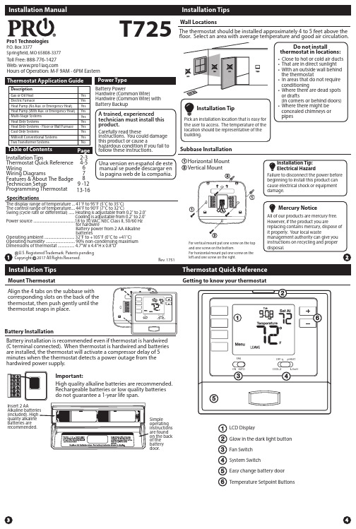
Pro1 Technologies T725电子温度调节器安装手册说明书
T725Pro1 TechnologiesToll Free: 888-776-1427 Web: Hours of Operation: M-F 9AM - 6PM EasternBattery PowerHardwire (Common Wire)Hardwire (Common Wire) with Battery BackupA trained, experienced technician must install this product.Carefully read theseinstructions. You could damage this product or cause ahazardous condition if you fail to follow these instructions.Una version en español de este manual se puede descargar en la pagina web de la compañia.Rev. 1751U.S. Registered Trademark. Patents pendingCopyright 2017 All Rights Reserved.Installation TipsThermostat Quick Reference WiringWiring DiagramsFeatures & About The BadgeTechnician Setup Programming Thermostat 4-56 7813-16Subbase Installation The thermostat should be installed approximately 4 to 5 feet above the floor. Select an area with average temperature and good air circulation.• Close to hot or cold air ducts • That are in direct sunlight • With an outside wall behind the thermostat• In areas that do not require conditioning• Where there are dead spots or drafts(in corners or behind doors)• Where there might be concealed chimneys or pipesWall LocationsVertical MountHorizontal MountFor vertical mount put one screw on the top and one screw on the bottom.For horizontal mount put one screw on the left and one screw on the right.Do not installthermostat in locations:Mount ThermostatAlign the 4 tabs on the subbase with corresponding slots on the back of the thermostat, then push gently until the thermostat snaps in place.Battery InstallationBattery installation is recommended even if thermostat is hardwired (C terminal connected). When thermostat is hardwired and batteries are installed, the thermostat will activate a compressor delay of 5 minutes when the thermostat detects a power outage from the hardwired power supply.Important:High quality alkaline batteries are recommended. Rechargeable batteries or low quality batteries do not guarantee a 1-year life span.Insert 2 AAquality alkaline batteries are recommended.Simple operating instructions are found on the back of the battery door.Getting to know your thermostatGlow in the dark light button Fan Switch System SwitchEasy change battery door Temperature Setpoint ButtonsLCD DisplayThermostat Quick ReferenceSpecificationsThe display range of temperature ... 41˚F to 95˚F (5˚C to 35˚C)The control range of temperature.... 44˚F to 90˚F (7˚C to 32˚C)Swing (cycle rate or differential) ...... Heating is adjustable from 0.2˚ to 2.0˚ Cooling is adjustable from 0.2˚ to 2.0˚Power source ...........................................18 to 30 VAC, NEC Class II, 50/60 Hz for hardwireBattery power from 2 AA Alkaline batteriesOperating ambient ............................... 32˚F to +105˚F (0˚C to +41˚C)Operating humidity .............................. 90% non-condensing maximum Dimensions of thermostat ................. 4.7”W x 4.4”H x 0.8”D9 -12FAN ON AUTO EmHCOOL OFF HEATP .O. Box 3377Springfield, MO 65808-3377Tech SettingsTech SettingsThis thermostat has a technician setup menu for easy installerconfiguration. To setup the thermostat for your particular application:Swing Setting TipTemperature swing, sometimes called differential or cycle rate, can be customized for this individual application. For most applications choose a swing setting that is as long as possible without making the occupants uncomfortable.Technician Setup MenuLCD Will Show temperature display to read 4˚above or below the factory Tech SettingsAdjustment OptionsDefaultreminder from OFF to 2000 hours of runtime in 50 hour NEXT STEP or PREV Note: Only press the DONE key when you want to exit the Technician Setup options.1. Press the MENU button2. Press and hold TECH SET button for 3 seconds. This 3 second delay is designed so that homeowners do not accidentally access the installer settings.3. Configure the installer options as desired using the table below.Tech SettingsAdjustment OptionsDefaultadjustable from 0.2˚ to 2˚. For example: A swing setting of Use the and key to Use the and to select 12 LCD Will Show Setpoint: Displays the user selectable setpoint temperature.Hold is displayed when the thermostat program is permanently overridden.Note: The Compressor delay feature is active if these are flashing.Stages: Indicates the stages of heat that are active.78Tech Settings2H/1C Heat Pump System - Factory Default SettingTypical 2H/1C Heat Pump System with separate emergency heatCConventional System 1H/1C, 2H/1C (Heat pump set to “OFF” in tech settings)Note: Thisthermostat is only compatible with ONE transformer systems.(HOT)Permanent Hold : If you press the HOLD key on the left of yourscreen, you will see HOLD appear below the setpoint temperature in To Return to Running Schedule : Press the RUN SCHED button on the left of your screen to exit either temporary or permanent hold.Filter Change ReminderIf your installing contractor has configured the thermostat to remind you when the air filter needs to be changed, you will see FILT in the display when your air filter needs to be changed.Resetting the filter change reminder: When FILT reminder is displayed, you should change your air filter and reset the reminder by holding down the second button from the top left side of the thermostat for 3 seconds.Gently slide a screwdriver into the bottom edge of the badge. Gently turn the screwdriver counter clockwise. The badge is held on by a magnet in the well of the battery door. The badge should pry off easily. DO NOT USE FORCE.About The BadgeAll of our thermostats use the same universal magnetic badge. Visit the company website to learn more about our free private label program.Magnet in doorUse the bevel on lower ridgeUse the and key to se-Next StepNext StepUse the and key to turn Tech SettingsAdjustment OptionsDefaultLCD Will Show Use the or key to turn Use the or key to select OFF, 5, 10, 15, 30, 45, 60, Next StepNext StepPrev StepUse the or key to select 1-stage or 2-stage operation.Tech SettingsAdjustment OptionsDefaultLCD Will Show Tech SettingsNext StepPrev StepProgrammingProgrammingSet Program Schedule 5+1+1 or 7 Day (Continue... )Set Program Schedule 5+1+1 or 7 DayYou can also use these time saving functions. You must be in Set Sched Programming Mode (Press Menu >> Press Set Sched ) for the following functions to work:1) To copy ALL time periods and temperatures of current system and day to ALL days, Press and Hold 2nd button down on left until the Days and Time flash.2) To copy ALL time periods (only times) for ALL days to the opposite system (Heat to Cool / Cool to Heat), Press and hold the Glow in the Dark Light button down until Set Time and Time flash.1. Select HEAT or COOL with the system switch. Note: You have to program heat and cool each seperately.2. Press the MENU button (If menu does not appear first press RUN SCHED )3. Press SET SCHED . Note: Monday-Friday or (Monday if in 7 Day) is displayed and the WAKE icon is shown. You are now4.5. Press NEXT STEP6. time period.7. Press NEXT STEP8. Repeat steps 4 thru 7 for that day’s LEAVE time period, RETURN time period, and SLEEP time period.To customize your program schedule, follow these steps:Repeat steps 4 through 7 for the Saturday WAKE time period, LEAVE time period, RETURN time period, and for the Saturday SLEEP time period.Saturday:Repeat steps 4 through 7 for the Sunday WAKE time period, LEAVE time period, RETURN time period, and for the Sunday SLEEP time period.Sunday:。
ZXR10 T16C电信级路由交换机安装手册共57页word资料

技术文件技术文件名称:ZXR10 T16C电信级路由交换机安装手册技术文件编号:版本:V1.0文件质量等级:共63 页(包括封面)拟制用服部路由器小组审核会签标准化批准深圳市中兴通讯股份有限公司前言安全信息: 一级激光收发器ZXR10 C系列路由器可以使用一级激光收发器。
安装或操作下列产品前请阅读如下安全信息:一级激光收发器使用光反馈环路来保持一级操作极限。
这个控制环路消除了对维护检查或调整的需求。
输出系厂家成套设施,不允许任何用户进行调整.。
一级激光收发器与下列安全规范一致:• 21 CFR 1040. 10 和1040.11, 美国健康与人类服务部(FDA)• 国际电工委员会(IEC)出版刊物825• CENELEC EN 60825 欧洲电工规范委员会在性能限制范围内操作时, 激光收发器输出符合所有以上三个规范的容易达到的一级发射限度。
一级范围内各种激光辐射程度没有危险性。
激光辐射和连接器当连接器到位时, 所有激光辐射保持在光纤之内.。
离开光纤(正常条件下)的最大辐射功率为2. 6 dBm 或55 x 10 -6 瓦特。
从收发器里去掉光连接器就允许激光辐射直接从光端口发出。
在最坏条件下, 从光端口的最大辐射为0. 8 W cm -2或8 x 10 W m sr。
勿用光学仪器查看激光输出。
使用光学仪器查看激光输出会增加对眼睛的伤害。
查看输出光端口时,务必将功率从网络适配器除去。
安全信息: WICT1- 12 T1卡警告:为避免火灾, 只能使用26号AWG或更大的电信线缆。
消费者信息及要求1.在该设备的DS1/ E1 WAN模型上有一个标签,里面除了其他信息外,还有注册号码和该设备的套环等值号码(REN)。
如果用户有要求, 可把该信息提供给你的电话公司。
2.REN用来决定你可以连接到你的电话的设施的数量,而且当你的号码被呼叫时,所有这些设施都会振铃。
在大多数地区但不是所有的地区,所有设施的REN总数不得超过5(5. 0)。
TECDIS 安装手册说明书

Chapter 6: Checklist regarding installation6.1 Checklists prior to completion of TECDIS installation.Item: Task to be performed: OK:Comments 1 Verify that all selected ports are receiving/transmittingdata, and that ports have been given names on bothmain and back-up TECDIS. Names shall be accordingto the data they are receiving/transmitting.2 Verify that sensor data is correctly distributed betweenmain and back-up TECDIS (NMEA server program).3 Verify that one single action do not result in loss ofposition on both main and back-up TECDIS.4 Verify that main and back-up TECDIS and respectiveequipment are connected to a proper UPS.5 Verify that boat size are correct compared to chart onboth main and back-up TECDIS.6 Perform monitor color calibration on main and back-upTECDIS.7 Verify that alarm function on both main and back-upTECDIS is working properly.8 Check that TECDIS transmits alarm to externalsystems.9 If installed, verify generation of conning picture andcorrect display of sensor data on conning monitor(check against engine telegraph, speed repeaters, gyrorepeaters etc)10 Verify audible signal from alarm speaker on TECDIS11 Verify sensor data (correct size of vessel etc) is filled inon main and back-up TECDIS.12 Verify that back-up of default setup values have beenperformed (save setup default values) on main andback-up TECDIS.13 Verify that installed charts have been correctly installedon both main and backup TECDIS (if installed), andthat charts license matches.14 Unplug TECDIS USB-key, restart TECDIS to verify itstarts up in normal mode (chart program startsautomatically) and boat symbol and sensor data aredisplayed.15 Fill in hardware/software fact sheet and file it in shipsdocuments and in technician personal files.Item: Hardware Model/type: Serial no.Main1 KeyboardBack-up2 KeyboardMain3 ProcessorBack-up4 Processor5 Telchart alarm interfaceMain6 TrackballBack-up7 Trackball8 Analog signal collector9 MonitorMainBack-up10 Monitor11 Conningmonitorloudspeaker12 Alarminterface13 MOXA14 Additionalunitsunits15 Additionalunits16 AdditionalItem: Software Version: Description:1 TECDIS MainBack-up2 TECDIS3 C-Map SDK Main4 C-MAP SDK Back-upsoftware5 Additionalsoftware6 Additionalsoftware7 AdditionalItem: License Number: Description:1 TECDIS license # Main2 TECDIS license # Back-upNB: License for charts is not possible to list, as there is one license per chart.6.2 Checklists prior to completion of TECDIS TC and TECDIS AW installation.If installation includes Track Control functionality, the following tests must be performed.TECDIS 1 and 2No. Function RequirementResultsHarbour Acceptance Test (15 minutes)1 External dataGo to setup menu and verify NMEA inputs are valid. Checkinput values for position and course.TECDIS 1:□Good □NG □N/ATECDIS 2: □Good □NG □N/A2 External data Verify that TECDIS receives valid sensor data from a minimum of:• Two independent positioning sensors• Two independent heading sensors • A speed sensorTECDIS 1: □Good □NG □N/ATECDIS 2: □Good □NG □N/A3 Alarm system Verify that TECDIS is connected to a separate alarm system.TECDIS 1: □Good □NG □N/ATECDIS 2: □Good □NG □N/A4 System status Check that no alarms/warnings are pending in alarm window.TECDIS 1: □Good □NG □N/ATECDIS 2: □Good □NG □N/A5 Chart database 1,Select setup menu, chart utilities, chart licenses 2,Verify that licences are valid for intended voyage3,Click C-Map chart update4,Verify that charts are updated in update logTECDIS 1: □Good □NG □N/ATECDIS 2: □Good □NG □N/ASea Trial Test (15 minutes)6AIS and ARPA Targets(If present)2,Click the symbol button of [ARPA Targets].1,Activate ARPA on radar and select a target.3,Click the symbol button of [AIS Targets].AIS and ARPA Targets are displayed on the top of charts.TECDIS 1: □Good □NG □N/ATECDIS 2: □Good □NG □N/A7 Conning display (If present)Correct indication is shown at the each configured window onthe Conning Display. Verify that selected sensors used byheading, position is correctly indicated.TECDIS 1: □Good □NG □N/ATECDIS 2: □Good □NG □N/A8 Route Monitoring 3,Route is then shown on displayed charts.Before start TEST, routes must be created or transferred fromother TECDIS:1,Press the [Plan] key, icon with number 1 indicated is active.This means primary route will be selected. Choose a routewith boathook icon.2,Press [YES] icon to activate route.4,To display secondary route choose icon with button 2indicated. Repeat procedure as for primary route.5 To exchange primary and secondary route, press icon with1↔2 indicated.6. Observe that correct warings is activated as appropriate.7. Click alarm icon for display of alarms and warnings on route.8. Test that activating tracksteering is successful.TECDIS 1:□Good □NG □N/ATECDIS 2:□Good □NG □N/A9 Radar overlay(If present)Check that radar overlay from radar is displayed on display afterpressing radar overlay icon.TECDIS 1:□Good □NG □N/ATECDIS 2:□Good □NG □N/A10Aids tonavigationVerify that TECDIS handle different functions like;1. Disconnect position sensors and observe dead reckoningperformance, verify that alarm is given: pos sensor ½ lost.2. Activate track dialog and set past tracks visible by clickingon “show” icon.3. Enter manual fix, by activating “bearing” icon. Click oncenter button on mouse when mouse is in position of visualobject. Use observed gyro bearing to make a red line inchart towards estimated position. Repeat procedure to maketwo lines resulting in a cross bearing.4. Update charts, enter chart utilities menu, choose C-Mapcharts update. Use semi-auto update. Create a updaterequest file on memory stick.Send file to **************** and load received file intoTECDIS. Update loaded successfully shall be presentedwhen update Is completed.5. Activate a route in route menu. To alter at route underway,click on “Edit” icon in route menu. Modify route and click on“OK” icon. Route is now altered. When at track steeringmode, 3 waypoints are not allowed to alter, last waypoint,next waypoint and waypoint after next.6. Manual adjustment for position is available in setup menu,click on “nav. position offset” icon and a dialog box appear intop right corner of map. Enter offset values as appropriate.TECDIS 1:□Good □NG □N/ATECDIS 2:□Good □NG □N/AAnschütz NP 2025 PLUS Adaptive AutopilotNo.FunctionRequirementResults Harbour Acceptance Test (15 minutes)1 External dataCorrect number is shown at each box of below.“Heading”, “Speed”□Good □NG □N/A2 Heading Control 1,[HEADING CONTROL] is activated when steering mode switch is set to “auto”. Present heading is displayed in heading display and in preset heading display. Present heading is activated as set heading.2. Verify parameter settings for rudder, yawing, counterrudder, rudder limit, ROT limit and radius value. Verify modeof heading change, radius or R.O.T. mode by observing keylamp.3. Alter set course by either turn knob and push set button to acknowledge or push and turn knob. Observe correct rudder response.4. Observe rudder movement.5. Observe that max rudder limit is not exceeded.□Good □NG □N/A3 Steering Control 1,Rudder moves to 10 degrees PORT when SET HEADING isset by 20 degrees below Gyro heading.2,Confirm the actual rudder angle by rudder angle indicator. □Good □NG □N/A4 Function1. Change operating mode from hand to heading control at Track Control TECDIS , verify that correct mode is indicated on TECDIS and conning monitor also.2. Shift from heading control to manual mode by switchingsteering mode selector. Verify that change to manual mode is possible from all modes with a single operator action.□Good □NG □N/A5 Function1. Change set course 50 deg to starboard, off-heading alarm not to be activated during setting of new course. Alarm is de-activated for a time period that is a function of present course and new desired course. □Good □NG □N/A6 FunctionTest override tiller in modes: hand, heading control and trackcontrol. Autopilot to go to hand □Good □NG □N/ASea trial test (240 minutes)1 Heading Control Response and stability of "Heading Control” steering.1,Observed overshooting should max 2 deg on 10 deg course change and max 5 deg on 60 deg course change. 2,Repeat another side course change with same value.Starboard 10 deg turn with NAV FULL speed (If available).Port 10 deg turn with NAV FULL speed (If available). Starboard 60 deg turn with NAV FULL speed. Port 60 deg turn with NAV FULL speed.Tests to be repeated with half speed ahead.□Good □NG □N/A2 EMCTesting of interference of radio transmissions while in heading control, observe system while:1. Transmitting a call with FS-25702. Transmitting a call with VHF’s3. Transmitting a message with Felcom-15 1&24. Transmitting a call with Felcom-70 □Good □NG □N/A2Track Control Steering Steering function test should be performed as follow in the next lists "Track Control Test " and “Fail to Safe Properties”□Good □NG □N/ATrack Control System TestItems to be checked during sea trialNo. Item Content Result Remarks 1 The following units have to be tested priorto the Track Control test:ECDISAUTOPILOTSTEERING GEAR2 Route Create a test route for Track Control in keepingwith the vessel maneuverability as per shownexample attached (or import by file).3 Routemonitoring 1.Enter route menu, check that icon “1” isactivated (primary route). Use boathook to select route from previous test item. Click yes when asked to activate route.2.Check that route monitoring parameters areshown in right menu (XTE, next waypoint info etc. )4 Trackkeeping 1. Check that ship follows the test routeselected on ECDIS. *Recommend test speed is normal sea speed2. Check performance according item 1 with speedreduction applied in one turn.3. Check performance according item 1 withinducing current effect by using bow thrusterduring turn.5 Alarms 1. Set WP pre-warning and WP approach time onthe ECDIS as per drawing below. Verify that WPapproach Alarm is generated when the shipapproaches the WP.2. Verify that separate Alarm system activatesback-up navigator alarm when WP pre-warningand WP alarm on ECDIS is not acknowledged.3. Set alarm for gyro mis-match to minimum inTECDIS Setup program. Wait for alarm to beraised.4. Activate route and use “Heading Control” modeon autopilot. Steer outside channel limit togenerate XTE alarm.5. Set “Heading off” alarm low and use bowthruster to provoke a heading drift. Verify thatalarm is raised.Example of route for Track Control testingWPT 3: 135 deg turn port, WPT 5: 135 deg turn starboard (both with minimum radius*) WPT 4: 60 deg turn port, WPT 7: 60 deg turn starboard (both with 2 NM radius)* Minimum radius to be settled after calculations from yard.Fail to Safe PropertiesItem Fail TrackControl(TCS) Test Result1 Position sensor antennasto be blinded off. When either of position sensoracquisition stops, TCS emits alarm butcontinues to function utilizing acquiredposition from other position sensor,LOG, and GYRO. When both positionsensor acquisition stops, TCS emitsalarm but begins navigation utilizingestimated position made available byLOG and GYRO. Then it (after 10min)automatically switches to Radius modeand manual maneuver will be in effect.Remove No.1position sensorantennaRemove No.2position sensorantenna2 Disconnect positionsensor on a straight leg. Same as above Remove No.1/2position sensor3 Disconnect positionsensor during max radiusturn. Alarm will be emitted only from ECDISwhich places no influence on TCSfunction.Remove No.1position sensoroutput connectorduring maximumradius turn.4 Turn Heading ControlSystem rudder limit tomin value during minradius turn. Not available.Adjustment ofrudder limit is notavailable.5 Disconnect seriallink to headingcontroller duringstraight leg. Emits alarm and stops TCS functionsimultaneously. It automaticallyswitches to Radius mode and manualmaneuver will be in effect.Remove TrackControl connectionfrom ECDIS whilesailing straightahead.6 Disconnect seriallink to headingcontroller duringturn. Emits alarm and stops TCS functionsimultaneously. Automatically switchesto Radius mode and manual maneuverwill be in effect after turning to the pre-determined maximum degree.Remove signalcable exclusively inuse for Auto Pilotoutputted fromECDIS whileturning.7 Disconnect speed logduring straight leg/or turn. Although emits alarm, two positionsensor data inputted maintains thenormal function.Remove LOG inputoutputted to ECDISwhile turning.8 Simulate failure inECDIS.Same as item 5 or 6.Turn off ECDIS9 Simulate failure inconning display. Not influential Turn off ConningDisplay10 Disconnect rudderfeedback. Emits alarm by Alarm System. If thedeviation between order rudder angleand actual rudder angle is 5deg or more,the Alarm System emits alarm andfreezes the actual rudder angle at thistime.Remove rudderfeedback inputoutputted to AlarmSystem whileturning.* This test isdangerous !11 Simulate failure inAutopilot Emits alarm by Alarm System and stopsTCS function. Rudder angle is frozen atthis time.Remove powerconnection toautopilot whileturning.* This test isdangerous !12 Simulate failure inNo.1 gyro. Not influential Switchesautomaticallyfrom No.1 to No.213 Check that second gyrois automatic applied incase of failure in theactive gyro.Not influential6.3 Additional checklist prior to completion of TECDIS AW installationNo. Item Content Result Remarks 1 Conning Verify that when one of the ECDIS processorslose sensor data on one serial line, display ofsensor data (relevant according to failed serialline) on conning monitor is not affected.2 General Verify that installation is done according to blockdiagram for TECDIS AW system.3 General Verify that installation is done according tofunctional description given for TECDIS AWsystem.4 General Verify that required conning info according toNAUT AW requirements are displayed correctly.5 Gyro Verify that requirements set forth in section 1.7are fulfilled.6.4 Installation Notes6.5 Track-record of performed installationName of vessel:Date of installation:Name of technician:Checklist performed:During all installations this checklist shall be filled in, this is for verifying a properinstallation of the ECDIS system onboard.。
- 1、下载文档前请自行甄别文档内容的完整性,平台不提供额外的编辑、内容补充、找答案等附加服务。
- 2、"仅部分预览"的文档,不可在线预览部分如存在完整性等问题,可反馈申请退款(可完整预览的文档不适用该条件!)。
- 3、如文档侵犯您的权益,请联系客服反馈,我们会尽快为您处理(人工客服工作时间:9:00-18:30)。
畅捷通T+11.510安装手册1.安装前要准备的事项1.1运行环境1.1.1操作系统环境角色操作系统服务器模式(含应用服务器、数据库服务器)Windows2003Server+Service Pack2(企业版)(32位,64位) Windows2008Server R2(standard,enterprise)Windows2012Server(standard,enterprise)单机模式Windows XP+Sp3(32位)Windows7(Professional,Enterprise,Ultimate)(32位,64位)Windows8(Professional,Enterprise,Ultimate)(32位,64位)Windows2003Server +Service Pack2(企业版)(32位,64位)Windows2008Server R2(standard,enterprise)Windows2012Server(standard,enterprise)注意:需安装简体中文语言操作系统,且区域语言中正确设置日期格式显示。
1.1.2数据库环境MSSQLServer2005Enterprise+sp2(x86,x64)MSSQLServer2008R2(Standard、Enterprise)x64MSSQLServer2012(Standard、Enterprise)x86x641.1.3硬件环境服务器配置(不区分数据服务器与应用服务器):硬件参数Win2003、Win2008R2、Win2012环境CPU频率:>=Intel至强四核2.0G>=Intel至强八核2.0GRAM大小:>=4G>=8G磁盘转速:SAS10000或15000RPM转速SAS10000或15000RPM转速并发人数:大于10人小于30人大于30人单机配置:硬件参数WinXP、Win7、Win8CPU频率:>=Intel双核2.0GRAM大小:>=2G1.1.4帐套升级11.50到11.51的帐套升级更加自动化,当11.51安装过程中,如果检测到11.50的帐套会自动弹出升级界面,您只要勾选要升级的帐套并点击确定即可以完成升级,当然您也可以选择不升级。
注意事项:环境检测不支持远程调用,请在安装前把环境助手拷贝到本机运行2.安装盘内容2.1安装盘包括以下内容:安装目录说明备注T+畅捷通T+、安装手册目录CheckEnvironment T+环境检测程序及环境相关软件目录AQD畅捷安全盾安装程序目录POS端产品T+零售收银安装程序目录WINDOWSSP操作系统升级补丁包目录SQLSERVER2005SP2SQL2005SP2补丁目录Setup.exe畅捷通T+自运行启动界面文件autorun.inf自运行启动配置文件文件3.安装步骤注意事项:安装产品前请切换到超级管理员身份(administrator)登录系统后进行安装,否则可能因为系统权限问题导致产品安装失败、IIS配置等其他原因。
3.1安装前的准备3.1.1调整显示器设置和桌面分辨率为达到较好的显示效果,建议在1024*768,1280*1024,1400*1050分辨率下安装产品。
3.1.2磁盘空间和类型产品包至少需要1.5G的磁盘空间,产品需要安装在NTFS格式的磁盘分区。
3.2运行安装包:3.2.1运行【畅捷通T+】安装包请选择以下2种方式之一安装产品:1、运行安装光盘,双击AUTORUN.exe弹出界面选择【安装T+】2、运行<安装盘>\T+目录下的Setup.exe。
Autorun界面如下3.2.2稍等片刻出现畅捷通LOGO全屏界面3.2.3安装过程中可能出现的界面说明1、安装过程中若程序检测不到环境助手程序,请选择路径到CheckEnvironment2、安装过程介绍图无法正常显示遇到这种情况,请到adobe官网重新下载并安装flash11以上版本。
3、由于不同版本的flash对我们安装中的flash兼容性不同,如果安装中的flash出现如下问题,请用鼠标单击黑屏的地方即可4、安装过程弹出如下界面遇到这种情况,请更新环境检测工具(CheckEnvironment文件夹)版本与当前安装包版本匹配,并且将工具拷贝到本地磁盘中。
3.3安装步骤:3.3.1软件使用许可协议在许可协议页界面中点击【同意许可协议】进入下一个界面。
点击【打印】在预装打印机驱动的机器上可以打印许可协议内容。
3.3.2安装选项1、选择所需的【安装类型】,包括全部安装(单机)全部安装(服务器)应用服务器(IIS)数据库服务器【注意】本版本支持分离式部署,即一台电脑上安装应用服务器,另外一台电脑安装数据库服务器,请注意数据库服务器只支持默认实例(MSSQLSERVER),不支持其他实例名。
分离式部署时必须先安装数据库服务器后才能安装应用服务器,安装应用服务器前请将数据库服务器的机器名和IP地址添加到系统hosts文件中,具体路径位于\%Systemroot%\System32\Drivers\Etc文件夹中,如果系统安装在C盘,那么Hosts文件就在C:\Widows\System32\Drvers\Etc中。
通过记事本打开后新输入一行,IP地址要放在每段的最前面,映射的Host name(主机名)在IP后面,中间用空格分隔。
例如:10.10.71.144tongbak2、浏览并指定【安装路径】,注意安装所在路径的磁盘格式必须为NTFS,磁盘可用空间是否足够3、安装所在路径不能开启压缩,安装所在盘符不能开启磁盘配额。
4、根据安装类型,勾选安装选项,包括【安装演示账套】、【升级账套】、【安装环境检测工具】5、根据安装类型,配置连接数据库信息,此界面不校验数据库配置信息是否正确,若连接不成功,则会在安装过程中弹出重新配置数据库连接界面。
安装应用服务器时,数据库服务器地址必须不能为本机,否则弹出如下提示:安装数据库服务器时,请按界面提示手动配置sql server数据库。
3.3.3环境检测根据选择的安装类型,安装过程中自动进行后台环境检测。
如果检测中存在不符合的项,环境检测工具将自动修复不符合的项,例如修复.NET,如下图所示若修复失败或者无法修复,将会弹出环境检测结果界面,请查看界面中不符合的检测项并进行手动修复。
如果已经手动修复不符合项可以点击【继续安装】,否则请点击【关闭】,返回安装选项界面。
【环境检测】安装类型与检测项的说明:环境检测程序根据你选择的【安装类型】进行相关项的检测。
序号检测项目全部安装安装产品服务器安装数据库服务器1CPU2内存3操作系统4操作系统补丁5IIS×6Net framework4.0×7数据库×8数据库补丁×9数据库密码强度检测××10浏览器(IE)11物理内存地址扩展12硬盘格式监测13系统环境优化14当前用户权限【环境检测】修复的说明:系统及系统补丁:针对此项环境检测程序不做修复操作。
如果检测不符合,winXP x86,win2003x86系统请用产品安装光盘\WINDOWSSP目录下的系统补丁进行修复。
具体操作系统的对应的数据库软件见下表。
操作系统(简体中文)默认安装数据库软件Windows7无,建议手动安装或购买SQL2005标准版数据库并安装SP2以上补丁Windows8无,建议手动安装或购买SQL2012标准版数据库并安装SP2以上补丁Windows XP+Sp3无,建议手动安装或购买SQL2005标准版数据库并安装SP2以上补丁Windows Server2003+Sp2无,建议手动安装或购买SQL2008r2企业版数据库并安装SP1以上补丁Windows Server2008R2无,建议手动安装或购买SQL2008R2企业版数据库Windows Server2012无,建议手动安装或购买SQL2012企业版数据库IIS:Windows7x64、Windows8x64、windows2008R2、windows2012,环境检测程序将自动进行修复,此过程中需要输入administrator账户密码,请先确定是否启动该账户并设置登录密码,输入过程不显示密码位数,输入完成后按回车即可。
Windows XP x86,Windows server2003x86,Windows server2003x64环境检测将自动进行安装或配置,此过程中会提示您插入Windows系统光盘,否则操作系统弹出找不到安装文件的对话框。
(若身边没有操作系统光盘,环境检测工具中集成IIS_WINXP或IIS_WIN2003包来供用户选择IIS相关系统文件进行安装。
【注意】此IIS安装包未经微软发布,请慎用,由此产生的问题本公司不承担任何责任)。
Windows7x86,Windows8x86环境检测将自动进行安装和配置,无需手动参与。
若程序修复IIS失败,会弹出IIS安装手册,详见环境助手目录下的IISInstallationInstruction.pdf文件。
由于此文档需要PDF阅读工具打开,请事前装好PDF 阅读工具。
IE:若检测到IE版本不符合,环境助手将安装或升级windowxp,windows2003操作系统的IE至IE8。
请在安装产品成功后手动重启系统,否则在重启系统前将无法登录产品。
产品要求客户端最低浏览器版本为IE8,最高支持IE10。
目前只支持IE浏览器不支持其他浏览器,不支持64位IE浏览器。
【环境检测】打开的说明:1、通过安装盘目录下的CheckEnvironment文件夹可以直接打开环境检测工具2、安装产品进度条(图片下侧)显示当前正在进行检测或者修复的检测项。
3.3.4安装过程安装过程自动切换显示产品八大领域宣传介绍图片【小功能】安装过程点击介绍图,弹出图片列表,可以来回拉动滚动条查看每页介绍内容,为防止图片自动切换,可以点击界面右上角的停止按钮。
3.3.5系统库安装:如果您在之前的【安装选项】页面正确输入服务器地址、用户名、密码,则配置数据库将自动进行配置无需手动干预。
如果输入的信息有误,则会弹出数据库配置界面1、输入数据库服务器名称或点击右侧的“检测”按钮2、检测成功后请下拉选择需要创建系统库的数据库实例名),3、输入对应实例的sa登陆密码后,点击“连接测试”,4、修改数据库内存限制,给出建议值,建议不要修改。
5、数据库服务器是否为本机,如果是单独装应用服务器则此项需要选择“否”,其他情况默认选择“是”6、最后点击”确定”进行数据库配置并创建演示帐套,否则点击"关闭"直接退出。
