LP3120C用户手册
IC-3120工业控制器数据表说明书
DEVICE SPECIFICATIONSIC-3120Industrial ControllerDefinitionsWarranted specifications describe the performance of a model under stated operating conditions and are covered by the model warranty.Characteristics describe values that are relevant to the use of the model under stated operating conditions but are not covered by the model warranty.•Typical specifications describe the expected performance met by a majority of the models.•Nominal specifications describe parameters and attributes that may be useful in operation. Specifications are Characteristics unless otherwise noted.ConditionsSpecifications are valid for the range 0 °C to 55 °C unless otherwise noted.Physical CharacteristicsCaution You can impair the protection provided by the IC-3120 if you use it in amanner not described in this document.To clean the IC-3120, wipe it with a dry towel.Dimensions10.8 cm × 6.1 cm × 13.0 cm (4.3 in × 2.4 in ×5.1 in)Weight911 g (2.01 lb)ProcessorType Quad Core Intel Atom Processor E3845 Frequency 1.91 GHzOn-die L2 cache 2 MBOperating SystemSupported Operating Systems NI Linux Real-Time 64-bitWindows Embedded Standard 7 64-bitMemorySystem RAMCapacity 4 GBType DDR3LSpeed1333 MT/sNonvolatile storageCapacity 2 GBPower RequirementsNote Supply voltages are measured at the IC-3120 power connectors.System Power (V)Supply voltage10.8 to 26.4 VDCMaximum power input24 WIsolated Output Power (V ISO)Supply voltage 4.5 to 30 VDCPoE Power (V PoE)Supply voltage48 VDC +10%/-5%2| | IC-3120 SpecificationsReconfigurable FPGAType Spartan-6 LX25Number of flip-flops30,064Number of 6-input LUTs15,03238Number of DSP48A1 slices(18 × 18 multipliers)Number of RAM blocks52 (936 Kbits)Network PortStandard IEEE 802.3 Ethernet, 10BASE-T, 100BASE-TX, 1000BASE-TInterface RJ45Speed10, 100, 1000 MbpsPoE-Capable Network PortsNumber of ports2Standards IEEE 802.3 Ethernet, 10BASE-T, 100BASE-TX, 100BASE-T, IEEE 802.3af (PoE)compatibleInterface RJ45Speed10, 100, 1000 MbpsSupported PoE power classes0, 1, 2, 3PoE power output (per port)15.4 WUSB 2.0 PortsNumber of ports2Type USB 2.0, Hi-SpeedSpeed480 Mbit/sMaximum current 1 A, shared across both portsIC-3120 Specifications| © National Instruments| 3VGA PortMaximum resolution1920 × 1200 at 60 HzTTL Inputs/OutputsNumber of channels8Type BidirectionalOutput voltage range0 V to 5 VMaximum pulse rate 2 MHzMinimum pulse detected500 nsPower-on state Input (high-impedance), 10 kΩ pull-up to 5 V Logic levelsInput low voltage0.59 V maximumInput high voltage 2.57 V minimumOutput low voltage0.38 V maximum at 1.5 mAOutput high voltage 4.12 V minimum at 1.5 mADifferential Inputs/OutputsNumber of channels2Types Bidirectional RS-422/RS-485 or single-endedinputMaximum pulse rate 5 MHz, differentialDifferential input threshold±200 mVDifferential output voltage 2.0 V min (R LOAD = 100 Ω, RS-422)Input voltage range0 V to 5.5 VTTL-compatible single-ended logic levelsInput low voltage0.8 VInput high voltage 2.0 VIsolated InputsType Current sinkingNumber of channels84| | IC-3120 SpecificationsInput voltageInput voltage range0 V to 24 VInput OFF voltage0 V to 2.0 VInput ON voltage 3.3 V to 24 VTurn-on current 2.5 mAMaximum pulse rate100 kHzMinimum pulse detected10 µsInput protectionReverse polarity protection Yes, -30 VInput voltage (channel to C ISO)30 V maximumInput current 3.3 mA, internally limitedIsolated OutputsType Current sourcingNumber of channels8Supply voltage (V ISO)Supply voltage range (V ISO) 4.5 to 30 VDCReverse polarity protection Yes, -30 VMaximum output voltage dropV ISO = 5 V 1.08 V at 35 mAV ISO = 24 V 1.18 V at 80 mAMaximum output currentV ISO = 5 V35 mAV ISO = 24 V80 mAMaximum current limit345 mAMinimum pulse rate 2.5 kHz (load of 100 kΩ, 300 pF)Maximum pulse rate20 kHz (load of 10 kΩ, 300 pF)Minimum pulse generated400 µsNote The isolated outputs have a current limit which will turn off the outputs incase the limit is exceeded. The circuit resets when the output is turned off. Do notdraw more than 100 mA from any 24 V isolated output. Do not draw more than50 mA from any 5 V isolated output. Do not draw more than 640 mA combinedfrom the V ISO pins on the 44-pin D-SUB connector.IC-3120 Specifications| © National Instruments| 5EnvironmentalIndoor use only.Ingress protection (IEC 60529)IP40Temperature (IEC 60068-2-1 and IEC 60068-2-2)Operating0 °C to 55 °CStorage-20 °C to 85 °COperating humidity (IEC 60068-2-56)10% RH to 90% RH, noncondensing Storage humidity (IEC 60068-2-56)5% RH to 95% RH, noncondensing Pollution degree (IEC 60664)2Maximum Altitude2,000 mOperating shock (IEC 60068-2-27)50 g, 3 ms half sine, 3 shocks per side 30 g, 11ms half sine, 3 shocks per sideOperating vibrationRandom (IEC 60068-2-64)10 to 500 Hz, 5 g rmsSwept Sine (IEC 60068-2-6)10 to 500 Hz, 5 gSafetyThis product is designed to meet the requirements of the following electrical equipment safety standards for measurement, control, and laboratory use:•IEC 61010-1, EN 61010-1•UL 61010-1, CSA 61010-1Note For UL and other safety certifications, refer to the product label or the OnlineProduct Certification section.Electromagnetic CompatibilityThis product meets the requirements of the following EMC standards for electrical equipment for measurement, control, and laboratory use; for radio equipment; and for telecommunication terminal equipment:•EN 61326-1 (IEC 61326-1): Class A emissions; Industrial immunity•EN 55011 (CISPR 11): Group 1, Class A emissions•EN 55022 (CISPR 22): Class A emissions•EN 55024 (CISPR 24): Immunity•AS/NZS CISPR 11: Group 1, Class A emissions•AS/NZS CISPR 22: Class A emissions6| | IC-3120 Specifications•FCC 47 CFR Part 15B: Class A emissions•ICES-001: Class A emissionsNote In the United States (per FCC 47 CFR), Class A equipment is intended foruse in commercial, light-industrial, and heavy-industrial locations. In Europe,Canada, Australia and New Zealand (per CISPR 11) Class A equipment is intendedfor use only in heavy-industrial locations.Note Group 1 equipment (per CISPR 11) is any industrial, scientific, or medicalequipment that does not intentionally generate radio frequency energy for thetreatment of material or inspection/analysis purposes.Note For EMC declarations and certifications, and additional information, refer tothe Online Product Certification section.CE ComplianceThis product meets the essential requirements of applicable European Directives, as follows:•2006/95/EC; Low-V oltage Directive (safety)•2004/108/EC; Electromagnetic Compatibility Directive (EMC)Online Product CertificationRefer to the product Declaration of Conformity (DoC) for additional regulatory compliance information. To obtain product certifications and the DoC for this product, visit / certification, search by model number or product line, and click the appropriate link in the Certification column.Environmental ManagementNI is committed to designing and manufacturing products in an environmentally responsible manner. NI recognizes that eliminating certain hazardous substances from our products is beneficial to the environment and to NI customers.For additional environmental information, refer to the Minimize Our Environmental Impact web page at /environment. This page contains the environmental regulations and directives with which NI complies, as well as other environmental information not included in this document.IC-3120 Specifications| © National Instruments| 7Waste Electrical and Electronic Equipment (WEEE)EU Customers At the end of the product life cycle, all NI products must bedisposed of according to local laws and regulations. For more information abouthow to recycle NI products in your region, visit /environment/weee.Battery Replacement and DisposalBattery Directive This device contains a long-life coin cell battery. If you need toreplace it, use the Return Material Authorization (RMA) process or contact anauthorized National Instruments service representative. For more information aboutcompliance with the EU Battery Directive 2006/66/EC about Batteries andAccumulators and Waste Batteries and Accumulators, visit /environment/batterydirective.电子信息产品污染控制管理办法(中国RoHS)中国客户National Instruments符合中国电子信息产品中限制使用某些有害物质指令(RoHS)。
LD32CNP10传感器系列说明书

Product DescriptionThe LD32CNP10 sensor family comes in a compact 12 x 32x 20 mm reinforced PMMA/ABS-housing.The sensors are useful in applications where high-accuracy detection as well as small size is required.The T each-In function foradjustment of the sensitivity makes the sensors highly flexible. The output type is preset (NPN or PNP), and the output switching function is programmable (NO or NC).The small laser spot makes it possible to detect small objects very precisely.•Miniature sensor range•Range: 0.1-1 m, with reflector•Sensitivity adjustment by Teach-In programming •Modulated, red laser light 650 nm, polarized (class 2)•Supply voltage: 10 to 30 VDC•Output: 100 mA, NPN or PNP preset•Make and break switching function programmable •LED for output indication and power ON•Protection: reverse polarity, short circuit and transients •Cable and plug versions •Excellent EMC performancePhotoelectricsLaser, Retro-reflective, PolarizedType LD32CNP10Type SelectionHousing Range Ordering no.Ordering no.W x H x D S n NPN & PNP cableNPN & PNP plugMake & break switching Make & break switching 12 x 32 x 20 mm1.0 mLD 32 CNP 10 NPT LD 32 CNP 10 NPM5T LD 32 CNP 10 PPTLD 32 CNP 10 PPM5TSpecificationsOperation DiagramInstallation HintsRelief of cable strain Protection of the sensing face Switch mounted on mobile carrier To avoid interference from inductive voltage/current peaks, separate the prox. switch pow-er cables from any other power cables, e.g.motor, contactor or solenoid cablesIncorrectCorrectThe cable should not be pulled A proximity switch should not serve asmechanical stopAny repetitive flexing of thecable should be avoidedLD32CNP10Specifications (cont.)Wiring Diagramstv = Power ON delayDelivery Contents•Photoelectric switch: LD 32 CNP 10•Installation instruction•Packaging:Cardboard boxSignal Stability IndicationAccessoriesLD32CNP10DimensionsFor further information refer to “Accessories”AdjustmentSensitivity adjustment, with static object (needed fortransparent objects only)1.Line up the sensor with the reflector. Yellow LED andgreen LED are ON.2.Press the button for 3 s until both LED’s flashsimultaneously (the first switching point is stored).3. Place the object in the detection area.4. Press the button for 1 s.a)The green LED flashes and stays ON: thesecond switching point is stored, and the sensoris ready to operate.b)Both LED’s flash simultaneously: the sensorcannot detect the object, no switching pointsare stored.for 3 s until both LED’s flash simultaneously.2.Press the button again for 1 s (without object). Thesensor is set to maximum sensitivity.Sensitivity adjustment, with a running process (needed for transparent objects only)1.Line up the sensor with the reflector. Green LED is ON.At this stage the status of the yellow LED can beignored.2.The running process must be the only “object” withinthe detection area. Press the button for 3 s until bothLED’s flash simultaneously.3.Press the button for at least the duration of one pro-cess cycle.a)The green LED flashes and stays ON: bothswitching points have been stored, and the sen-sor is ready to operate.b)Both LED’s flash simultaneously: the sensorcannot detect the object, no switching pointsare stored.1.Press the button for 13 s.2.Release the button: the green LED flashes.3. While the green LED flashes, the output is invertedeach time the button is pressed. This is indicated bythe yellow LED.When the button is not pressed for 10 s, the currentoutput function is stored.The sensor is now ready for operation.Default setting1.Cover light emitter and receiver:3 s, until both LED’s flash simultaneously.2.Press the button for 1 s.NB!The Teach Input (2 WH) will work similarly to the push button, active High.LD32CNP103 s1 cycle13 s3 s 1 s。
Echelon PL3120透传载波模块使用手册

1概述Echelon PL3120透传载波模块(以下简称模块)是采用Echelon的PL智能收发器,实现TTL Uart转电力线载波通信、电力线载波通信转TTL Uart的通信模块;PL智能收发器为在日常设备中添加LONWORKS电力信号和网络提供了一个简单,性价比高的解决方案。
由于遵从开放的ANS/EIA标准,PL智能收发器在网络,音视频,照明,制冷/制热,安全,测量和灌溉应用中的理想选择。
几乎在今天所有的工业应用中都出现了远离专有控制结构和中央控制系统这样一种潮流。
由于基于LONWORKS的解决方案提供了更好的内部交互性,更稳定的技术,更快的开发时间,更佳的性价比,把控制系统转移为开放,分布式,点对点的LONWORKS 网络得到了快速的发展。
所有在LONWORKS网络上的日常设备都使用ANSI/EIA 709.1协议标准进行通信。
这个七层ISO协议为网络设备提供了一系列的服务,允许设备中的应用程序在对网络拓扑和其他设备的功能一无所知的情况下,与其他网络设备进行信息的交流。
2主要技术指标与特点2.1技术指标1.采用86kHz/75kHz(双频自动切换)BPSK调制方式;2.电力线载波通信速率高达3600bps;3.Uart口采用5V TTL电平、9600bps、8位数据、1位停止位、无校验方式;4.采用透明传输方式;5.采用可预测的p-CSMA算法,支持对等网络,电力线网络中模块可同时发送;6.采用控制网络LONWORKS技术;2.2技术特点2.2.1双载频工作PL智能收发器利用双载波频率信号技术,使其在面对干扰噪声源时,提供了超高的通信可靠性。
在信道确认的情况下,数据包初始在主载频上传输;在信道条件未知的情况下,数据包将会有选择的在主载频和次载频上传输。
2.2.2前向纠错技术大量的噪声源会通过损坏数据包而干扰电力线信号。
除了循环冗余检测(CRC)外,PL智能收发器还使用高效,low-overhead的前向纠错算法来克服包错误。
工频GPi3110-120KVA使用说明书

工业型 UPS 10-120KVA31使用说明书目录1. 产品介绍 (1)1.1 简介 (1)1.2 基本组成 (1)1.3 工作模式 (1)1.4 产品概览 (5)2. 注意事项 (6)2.1 常用标志说明 (6)2.2 安全事项说明 (6)3. 机柜安装 (9)3.1 安装环境要求 (9)3.2 卸货开箱 (10)4.电气安装 (11)4.1 电源端口 (11)4.2 通讯端口 (14)5. 调试 (17)5.1 开机步骤 (17)5.2 关机步骤 (17)5.3 维修旁路使用步骤 (18)6. 人机界面 (18)6.1 控制面板 (18)6.2 液晶屏显示说明 (19)6.3 功能菜单操作说明 (21)7. 使用维护指南 (36)7.1 系统维护 (36)7.2 电池维护 (36)8. 故障诊断及处理 (37)8.1 警告代码说明 (37)8.2 故障代码说明 (37)9. 单机电气规格 (38)10. 并机安装指导 (40)10.1 概述 (40)10.2 并机安装 (41)10.3 并机设置及LCD显示 (45)10.4 并机规格 (46)10.5 并机故障诊断及处理 (46)1. 产品介绍1.1 简介此系列UPS是一款纯正弦波输出的双变换在线式不间断电源系统,为重要负载提供不受电网干扰、稳压、稳频的电力供应的电源设备。
当市电掉电后,UPS将电池能量逆变输出到负载,实现不间断输出。
本系列UPS采用输出隔离变压器的高频双变换结构和先进的全数字控制技术,实现稳定、干净、不间断电源输出。
同时还提供多样化的通讯方案,及友好的人机界面,方便用户对机器进行设置及监控。
通讯部分提供MODBUS,RS232以及可扩展的智能插槽。
1.2 基本组成本系列UPS系统主要由整流模块和逆变模块组成交流到直流再到交流的双变换电路、静态旁路、维修旁路、电池充放电回路等几个主要的模块组成。
市电与旁路通过反向并联的可控硅作为切换开关来进行切换。
pxut320c操作手册
第一章序言●感谢您使用友联公司的产品,您能成为我们的用户,是我们莫大的荣幸。
PXUT-320C型全数字智能超声波探伤仪采用国际先进的数字集成技术和新型TFT彩色显示器件,其各项性能指标均达到或超过国际先进水平。
仪器采用人工智能技术,功能强劲,使用方便。
为了您能尽快熟练掌握该款超声波探伤仪,请务必仔细阅读本操作手册以及随机配送的其他相关资料,以便您更好地使用探伤仪。
●请您仔细核对您所购仪器及其配件与装箱单是否一致,如不一致请您拒收并立即与友联公司联系;购买仪器后,请您认真仔细地阅读仪器的相关资料,以便了解您应有的权利和义务。
●友联公司生产的数字超声波探伤仪是设计先进、制造精良的高科技产品,在研发和制造过程中经过了严格的技术评测,具有很高的可靠性。
即使如此,您仍可能会在使用中遇到一些问题,甚至会对该产品质量产生怀疑。
为此,我们在手册中进行了详细说明,以消除您的疑虑。
如果您在仪器使用过程中遇到问题,请查阅本操作手册相关部分(特别是第九章),您也可以在友联网站BBS上发贴提问,或直接与友联公司联系。
感谢您的合作。
声明●因版权所有,未经友联公司的书面许可不得翻印或以其它任何形式或方法使用此印刷资料或软件中的某个部分。
友联公司对此印刷资料或软件中所含资讯之使用或因此而造成的损害一概不予负责。
友联公司有权更改此印刷资料或软件之特征及内容,恕不征求意见或事先通告。
●可通过以下任一种方式与友联公司取得联系:服务热线:************,5296971电子邮件:********************公司网址:/●、、友联、UNION均为南通市友联智能仪器公司注册商标。
Epson为精工公司拥有商标,Hp为惠普公司商标,Microsoft 和Windows为微软公司拥有商标,其他品牌及商品名称属于所有者的资产。
1-1安全●使用指定的电源类型,如有不详情况请与友联公司或经销商联系。
●不要在插头连接松弛的地方使用充电器。
CTP3110终端综测仪用户使用手册-通用设置

——通用设置1设备使用常规设置 (3)1.1开机启动 (3)1.2设置通道 (4)1.3SETUP功能键设置 (5)1.3.1时钟设置 (5)1.3.2GPIB设置 (6)1.3.3版本查询 (7)1.3.4授权查询 (7)1.3.5Log打印设置 (8)1.3.6PRINT功能 (8)2工作模式 (9)2.1.1Active Cell工作模式 (9)2.1.2Cell Off工作模式 (9)2.1.3CW工作模式 (9)2.1.4Analysis工作模式 (9)2.1.5Non-Signaling工作模式 (10)2.1.6Quick Cal工作模式 (10)1设备使用常规设置1.1开机启动1) 开机,启动CTP3110 终端综测仪:确定综测仪已经连接交流电源并打开仪表后面板的电源开关;按下仪表前面板左下角电源启动Power 键,启动综测仪。
图1-1 综测仪CTP3110启动界面2) CTP3110 终端综测仪初始化,并进入初始界面,见图2-1 。
3) 开机初始化完成后,综测仪进入默认页面,如图2-2所示:图2-2 综测仪CTP3110启动成功后默认界面1.2设置通道1.设置综测仪通道模式:按MODE键,进入图2-3界面,选中相应的通道按ENTER键可分别对各个通道进行模式设置,如图2-4。
设置完毕后,按 键,关闭参数设置窗口;图2-3 进入综测仪通道模式设置界面图2-4 综测仪通道2模式设置1.3SETUP功能键设置点击前面板左侧区域SETUP键,(见前面板介绍)会弹出如下图对话框:图2-6 SETUP功能键设置1.3.1时钟设置SETUP选项中的前三行是时钟设置,其中Ref.clock是输入参考信号(10MHz),可选择内部参考信号或外部参考信号;Tri.clock是输入trigger信号,可选择内部trigger或外部trigger;Out.TriClock是输出trigger信号,可选择不同的输出trigger频率(如图2-7)。
IP 系列单相逆变器操作说明书
IP系列单相逆变器操作说明书迅昌电气(上海)有限公司CINTRONG ELECTRICITY(SHANGHAI)CO.,LTD.苏州迅昌电力电子有限公司SUZHOU CINTRONG POWER ELECTRONICS CO.,LTD.重要提示:该设备符合以下参考标准IEC60950-1,IEC62040-1-1使用操作区一般安全IEC/EN62040-2EMC要求IEC62040-3性能要求和测试方法设备的安装应遵照以上要求并使用厂家指定附件。
本手册涉及IP工频逆变电源的相关安装与运行资料,请在安装前详细阅读本手册。
该设备内部有整流滤波电容,是储能元件,在关断输入交流电源后,直流部分可能仍有电压,请注意人身安全。
该设备安装有射频干扰(RFI)滤波器。
对地漏电流在3.5mA~1000mA之间。
在选择瞬变漏电流断路器(RCCB)或其它漏电检测仪器(RCD)时应考虑设备启动时可能出现的瞬态和稳态对地漏电流。
必须选择对单向直流脉冲(A级)和瞬态电流脉冲不敏感的RCCB。
请注意负载的对地漏电流也将流过RCCB或RCD。
目录1产品介绍 (1)1.1概述 (1)1.2设计思想 (1)1.3产品特点 (2)2搬运放置 (2)3使用环境 (2)4安装说明 (3)4.1初检 (3)4.1产品外形图 (3)5电气原理图(仅供参考) (4)6参数说明 (5)7电气连接 (5)8操作说明 (6)8.1准备开机 (6)8.2开机过程 (6)8.3关机过程 (6)9LCD说明 (6)9.1按键说明 (6)9.2参数显示 (7)10故障检修 (7)申明该手册仅适用于IP系列工频逆变电源产品,属通用版本。
技术指标详见技术合同或产品铭牌。
1产品介绍1.1概述IP工频逆变电源是迅昌公司采用ARM新一代32位处理器为核心,IGBT为执行元件,隔离变压器进行电压转换设计而成。
IP工频逆变电源采用DC-AC(直流-交流)的方式通过SPWM(正弦波脉宽调制)变换将输入电源转换成世界任何电源,以满足不同电压、不同频率的需要。
ISOCOM COMPONENTS ICPL3120 光电隔离驱动器说明书

DESCRIPTIONThe ICPL3120 consists of an Infrared Light Emitting Diode optically coupled to an Integrated Circuit with a Power Driving Output. ICPL3120 is ideally suitable to drive the Power IGBT and MOSFET in Inverters of Motor Controls and in Power Supplies.The 2.5A peak output current is capable to direct drive IGBT/MOSFET up to ratings of 1200V/100A. For IGBTs with higher ratings, ICPL3120 can be used to drive a discrete power stage which drives the IGBT gate.FEATURES• ±2.5A Maximum Peak Output Current• 35kV/μs Minimum Common Mode Rejection at V CM 1500V• Maximum Propagation Delay 500ns• Maximum Propagation Delay Difference 100ns • Wide Operating Voltage Range V CC 15 to 30 V• Maximum Supply Current I CC 3.5mA• Under Voltage Lock Out (UVLO) Protection with Hysteresis• Guaranteed Performance over Temperature Range - 40°C to +105°C • MSL 1• Lead Free and RoHS Compliant • Safety Approvals PendingAPPLICATIONS• IGBT/MOSFET Gate Drive • UPS • Inverters• AC Brushless and DC Motor DrivesORDER INFORMATION• Add G after PN for 10mm lead spacing • Add SM after PN for Surface Mount•Add SMT&R after PN for Surface Mount Tape & ReelISOCOM COMPONENTS 2004 LTDUnit 25B, Park View Road West, Park View Industrial EstateHartlepool, Cleveland, TS25 1PE, United Kingdom Tel : +44 (0)1429 863 609 Fax : +44 (0)1429 863 581e-mail:***************.ukISOCOM COMPONENTS ASIA LTDHong Kong Office,Block A, 8/F, Wah Hing Industrial mansion,36 Tai Yau Street, San Po Kong, Kowloon, Hong Kong.Tel : +852 2995 9217 Fax : +852 8161 6292e-mail:****************.hkA 0.1μF bypass Capacitor must be connected between Pins 8 and 5. InputForward Current20mA Forward Current Rise / Fall Time500ns Power dissipation 45mW Reverse Voltage 5V Forward Peak Current (Pulse Width ≤ 1μs, 300pps) 1A Output Peak Output Current(Exponential waveform,Pulse Width ≤ 0.3μs, f ≤ = 15kHz)±2.5A Operating Frequency(Exponential waveform,I O(Peak) ≤ l2.5Al, Pulse Width ≤ 0.3μs) 50kHzSupply Voltage (V CC ‒ V EE )0V to 35V Output Voltage 0V to V CCPower Dissipation 250mW Isolation Voltage 5000V RMS Total Power Dissipation 295mW Operating Temperature -40 to 105 °C Storage Temperature -55 to 125 °C Lead Soldering Temperature (10s)260°C Total Package 1 NC2 Anode3 Cathode4 NC5 GND (V EE )6 V O7 V O8 V CCABSOLUTE MAXIMUM RATINGS (T A = 25°C)Stresses exceeding the absolute maximum ratings can cause permanent damage to the device.Exposure to absolute maximum ratings for long periods of time can adversely affect reliability.LEDV CC V EE(Turn ON, +ve going)V CC V EE(Turn OFF –ve going)V OOFF 030V 0 30V LOWON 011.0V 0 9.5V LOWTruth TableON 11.013.5V 9.5 12.0V TRANSITIONON 13.530V 12 30V HIGHParameter Symbol Min Max Unit Operating Temperature T A - 40 105 °CSupply Voltage V CC V EE 15 30 V Input Current (ON) I F(ON) 7 16 mA Input Voltage (OFF) V F(OFF) 0 0.8 V Recommended Operating ConditionsELECTRICAL CHARACTERISTICS (Typical Values at V CC V EE = 30V and T A = 25°C,Minimum and Maximum Values at Recommended Operating Conditions, unless otherwise specified)Parameter Symbol Test Condition Min Typ. Max UnitHigh Level Supply Current I CCH I F = 10mA, V CC = 30VV O = Open 2.4 3.5 mA Low Level Supply Current I CCL I F = 0mA, V CC = 30VV O = Open 2.5 3.5 mAHigh LevelOutput CurrentI OH Maximum Pulse Width = 50μsV O = V CC – 1.5V -1.0 AMaximum Pulse Width = 10μsV O = V CC – 4V -2.5 Low Level Output CurrentI OL Maximum Pulse Width = 50μsV O = V EE + 1.5V 1.0 AMaximum Pulse Width = 10μsV O = V EE + 4V 2.5 High Level Output Voltage V OH I F = 10mA, I O = -100mAV CC 0.3V CC 0.1V Low Level Output Voltage V OL I F = 0mA, I O = 100mA V EE +0.1 V EE +0.25 VUVLO ThresholdV UVLO+ V O > 5V, I F = 10mA 11.0 12.7 13.5 VV UVLO-V O < 5V, I F = 10mA9.511.212.0VUVLO Hysteresis UVLO HYS 1.5 VOUTPUT Parameter Symbol Test Condition Min Typ. Max UnitForward Voltage V FI F = 10mA1.2 1.37 1.8 V Forward Voltage TemperatureCoefficient ΔV F /ΔT I F = 10mA1.237mV/°CReverse Voltage V R I R = 10μA 5 V Input Threshold Current (Low to High) I FLH V CC = 30V V O > 5V 1.8 5 mA Input Threshold Voltage (High to Low) V FHL V CC = 30V V O < 5V 0.8 V Input CapacitanceC INV F = 0V, f = 1MHz33pFINPUTELECTRICAL CHARACTERISTICS (Typical Values at V CC V EE = 30V and T A = 25°C,Minimum and Maximum Values at Recommended Operating Conditions, unless otherwise specified)Parameter Symbol Test Condition Min Typ. Max UnitPropagation Delay Time to High Output Level t PLH I F = 7 to 16mA,V CC = 15 to 30V,V EE = 0V,Rg = 10Ω,Cg = 25nF,f = 10kHz,Duty Cycle = 50%50 130 500 nsPropagation Delay Time to Low Output Level t PHL 50130500Pulse Width Distortion |t PHL - t PLH| for any given device PWD570Propagation Delay Difference (t PHL - t PLH) between any two Devices PDD -100100Output Rise Time(10% to 90%)t r35Output Fall Time(90% to 10%)t f 35Common Mode Transient Immunity at High Output Level CM H I F = 10 to 16mA,V CC = 30V,V CM = 1500V,T A = 25°C35 50 kV/μsCommon Mode Transient Immunity at Low Output Level CM L V F = 0V,V CC = 30V,V CM = 1500V,T A = 25°C35 50 kV/μsSWITCHINGUVLO Turn Off Delay t UVLO OFF I F = 10mA, V O < 5V 0.4 μs UVLO Turn On Delay t UVLO ON I F = 10mA, V O > 5V 1.6 μsELECTRICAL CHARACTERISTICS (Typical Values at V CC V EE = 30V and T A = 25°C,Minimum and Maximum Values at Recommended Operating Conditions, unless otherwise specified)Note :1. A 0.1uF or bigger bypass capacitor must be connected across pin 8 and pin 5.2. PDD is the difference of t PHL and t PLH between any two ICPL3120 under same test conditions.3. Common Mode Transient Immunity in High stage is the maximum tolerable negative dV CM /dt on the trailing edge of the common modeimpulse signal, V CM , to assure that the output will remain high (V O > 15V).4. Common Mode Transient Immunity in Low stage is the maximum tolerable positive dV CM /dt on the leading edge of the common modeimpulse signal, V CM , to assure that the output will remain low (V O < 1V).Parameter Symbol Test Condition Min Typ. Max UnitInsulation Voltage V ISO R.H. = 40% - 60%, T A = 25°Ct = 1 min,5000 V Input - Output ResistanceR I-OV I-O = 500VDC1012ΩInput - Output CapacitanceC I-O f = 1MHz0.92 pFISOLATIONFig 1 Supply Current vs Supply Voltage Fig 2 Supply Current vs Ambient TemperatureFig 3 Transfer Characteristics Fig 4 Output Low Voltage vs Ambient TemperatureFig 5 Output High Voltage vs Ambient TemperatureFig 6 Output High Voltage Drop vsAmbient TemperatureFig 7 Input Threshold Current vs Ambient Temperature Fig 8 Propagation Delay vs Ambient TemperatureFig 9 Propagation Delay vs Forward Current Fig 10 Propagation Delay vs Supply VoltageFig 11 Propagation Delay vsSeries Load Resistance Fig 12 Propagation Delay vs Series Load CapacitanceFig 13 Forward Current vs Forward Voltage V OL Test CircuitI OH Test CircuitIOL Test CircuitV OH Test CircuitI FLH Test CircuitUVLO Test CircuitCMR Test Circuittr , tf, tPLH and tPHL Test CircuitORDER INFORMATIONDEVICE MARKINGAfter PN DescriptionPacking quantity NoneStandard DIP8 50 pcs per tube G10mm Lead Spacing 50 pcs per tube SM Surface Mount50 pcs per tube SMT&RSurface Mount Tape & Reel1000 pcs per reelICPL3120PN ICPL3120 ICPL3120G ICPL3120SM ICPL3120SMT&R ICPL3120I YWWICPL3120 denotes Device Part Number Y denotes 1 digit Year code WW denotes 2 digit Week code I denotes IsocomPACKAGE DIMENSIONS in mm (inch)DIPG FormSMDDescription Symbol Dimension mm (inch) Tape WidthW 16 ± 0.3 (0.63) Pitch of Sprocket HolesP 0 4 ± 0.1 (0.15) F 7.5 ± 0.1 (0.295) P 22 ± 0.1 (0.079) Distance of Compartment to CompartmentP 112 ± 0.1 (0.47)Distance of Compartment to Sprocket HolesRECOMMENDED SOLDER PAD LAYOUT (mm)TAPE AND REEL PACKAGINGIsocom Components is continually working to improve the quality and reliability of its products. Nevertheless, semiconductor devices in general can malfunction or fail due to their inherent electrical sensitivity and vulnerability to physical stress. It is the responsibility of the buyer,when utilizing Isocom Components products, to comply with the standards of safety in makinga safe design for the entire system, and to avoid situations in which a malfunction or failure ofsuch Isocom Components products could cause loss of human life, bodily injury or damage to property.In developing your designs, please ensure that Isocom Components products are used within specified operating ranges as set forth in the most recent Isocom Components products specifications.The Isocom Components products listed in this document are intended for usage in general electronics applications (computer, personal equipment, office equipment, measuring equipment, industrial robotics, domestic appliances, etc.). These Isocom Components products are neither intended nor warranted for usage in equipment that requires extraordinarily high quality and/or reliability or a malfunction or failure of which may cause lossof human life or bodily injury (“Unintended Usage”). Unintended Usage include atomic energycontrol instruments, airplane or spaceship instruments, transportation Instruments, traffic signal instruments, combustion control instruments, medical Instruments, all types of safety devices, etc... Unintended Usage of Isocom Components products listed in this documentshall be made at the customer’s own risk.Gallium arsenide (GaAs) is a substance used in the products described in this document.GaAs dust and fumes are toxic. Do not break, cut or pulverize the product, or use chemicals to dissolve them. When disposing of the products, follow the appropriate regulations. Do not dispose of the products with other industrial waste or with domestic garbage.The products described in this document are subject to the foreign exchange and foreign tradelaws.The information contained herein is presented only as a guide for the applications of our products. No responsibility is assumed by Isocom Components for any infringements of intellectual property or other rights of the third parties which may result from its use. No licenseis granted by implication or otherwise under any intellectual property or other rights of Isocom Components or others.The information contained herein is subject to change without notice.。
3010C使用说明书
DCAP-3010C(V3.0)电动机保护测控装置:使用说明书
1 概述
DCAP3010C电动机保护测控装置适用于各种容量及要求有纵差保护的高压电动机的保 护及测控。
2 装置主要功能配置
名称
保护
遥测量 遥信量 遥控量 当地报告记录 对时功能
说明
两段定时限过流保护(可受复压判据控制); 堵转保护; 反时限过流保护; 反时限负序过流保护; 负序过流保护; 过负荷保护; 过负荷告警; 三段零序过流保护; 零序过流告警; 过热保护; 过压保护; 低压保护; 负序过压保护; 差动速断保护; 带有 2 次谐波闭锁和 CT 断线闭锁的比率差动; 差流越限告警; 零序过压告警; 独立的接地选线功能; PT 断线、CT 断线、控制回路断线、装置失电告警; 2 路非电量保护(高温跳闸、高温告警); 4 路非电量控制(联跳 1、2、3、4); 故障、告警、闭锁等事件记录; 支持硬压板投退并可灵活整定; 多达 8 套保护定值及保护投退; 故障录波。 电压: Ua、Ub、Uc、Uab、Ubc、Uca、3U0; 电流: Ia、Ib、Ic,INa、INb、INc,3I0;
DCAP-3010C(V3.0)电动机保护测控装置
使用说明书
北京紫光测控有限公司
BEIJING UNISPLENDOUR M&C CO. , LTD
DCAP-3010C(V3.0)电动机保护测控装置:使用说明书
目录
1 概述.......................................................................................................................................3 2 装置主要功能配置...................................................................................................................3 3 装置硬件资源配置...................................................................................................................4 4 主要技术指标...........................................................................................................................4
防逆流控制柜用户手册
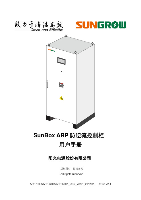
3 产品描述 ................................................................................................................... 7
5 安装 ......................................................................................................................... 38
5.1 安全须知 ....................................................................................................................................... 39 5.2 交付 .............................................................................................................................................. 40 5.3 安装设计 ....................................................................................................................................... 41
菲尼克斯电气ILC330_350可编程控制器用户手册
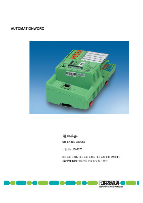
为了保证安全使用设备,建议您仔细阅读本手册。下列说明提供了使用本 手册的方法。
本手册用户群
本手册中描述的产品使用只针对合格的电气工程师及受到他(她)们指导 的人员,他(她)们应熟悉适用的标准及其它电气工程规则,特别是相关 安全概念。
菲尼克斯电气有限公司对于无视本手册中的信息而造成对菲尼克斯电气 有限公司或第三方公司的产品的错误操作或损坏,菲尼克斯电气有限公司 概不负责。
2.14 电源 .......................................................................................... 2-25 2.14.1 电源尺寸 ..................................................................... 2-25 2.14.2 电源连接 ..................................................................... 2-26 2.14.3 24 V分段电源/24 V主电源 ......................................... 2-28 2.14.4 24 V 分段电源 ............................................................ 2-28 2.14.5 24 V主电源 .................................................................. 2-28 2.14.6 24 V ILC电源............................................................... 2-28 2.14.7 跳接 ............................................................................. 2-28
苏州米加尼克焊接技术 PI 320 400 500 DC 说明书

PI 320/400/500 DCInstruction manual使用说明书2008年10月生效 C50333204_AEC DECLARATION OF CONFORMITYMIGATRONIC A/S Aggersundvej 33 9690 Fjerritslev Denmarkhereby declare that our machine as stated belowType: PI 320/400/500 DC As of Week 26 2007conforms to directives 2006/95/EC and 2004/108/ECEuropean Standards: EN/IEC60974-1EN/IEC60974-2 EN/IEC60974-3 EN/IEC60974-10 (Class A)Issued in Fjerritslev on 25th June 2007.Peter Roed Managing director目录1. 警告/电磁泄漏 (1)2. 焊机配置/准备工作 (2)3. 控制面板 (4)4. 技术参数 (10)5. 维护 (11)6. 保修条款 (11)7. 图纸 (12)8. 备用零件表 (15)9. 附英文说明书 (20)一致性声明警告电弧焊设备和电弧切割设备在操作或运用不当时,会对操作的人、工场附近的人、或附近的物品产生危险。
因此,必须严格按照相关的安全规则的指示使用设备。
您尤其需要注意以下的事项:电-必须根据安全规则安装焊机,并由合格的受过专业培训的人安装。
焊机必须接地线。
-确保焊机受到正确的保养。
-如若电缆或绝缘层有破损,必须立即停止工作,进行维修。
-维修和保养须由合格的受过专业培训的人进行。
-避免裸手接触任何带电的电路或部件,以及带电的电极或焊丝,必须使用无破损的焊接手套。
-确保与地面绝缘(如:穿上橡胶底鞋子)-用安全稳固的地方作工位(如:避免摔跌的危险)光和热辐射-即使是短暂的裸眼暴露于弧光也会对眼睛造成持续性伤害,请使用带防辐射滤镜的头盔保护。
Philips HTL3120 SoundBar 用户指南说明书
HTL3120_77_QSG_V2.0.indd 15
11/21/2013 4:35:09 PM
ES
Para obtener más información sobre este producto,
visite /support.
2013 © WOOX Innovations Limited. All rights reserved. Philips and the Philips’ Shield Emblem are registered trademarks of Koninklijke Philips N.V. and are used by WOOX Innovations Limited under license from Koninklijke Philips N.V. HTL3120_77_QSG_V2.0
HTL3120_77_QSG_V2.0.indd 16
11/21/2013 4:35:09 PM
COAXIAL AUDIO L/R 11/21/2013 4:35:04 PM
4
ES
Disfrute del audio y video de sus dispositivos
R HTL3120_77_QSG_V2.0.indd 7
HDMI IN HDMI IN HDMI OUT (ARC)
1
2
TO TV
The Bluetooth® word mark and logos are registered trademarks owned by Bluetooth SIG, Inc. and any use of such marks by WOOX Innovations is under license. Other trademarks and trade names are those of their respective owners.
立安山火灾报警控制器

目录第一章概述. . . . . . . . . . . . . . . . . . . . . . . . . . . . . . . . . . . . . . . . . . . . . . . . . . . . . . . . . . . . . . . . . . . . . . ..3第二章SAN030C火灾报警控制器面板说明. . . . . . . . . . . . . . . . . . . . . . . . . . . . . . . . . . . . 3第三章基本操作指南. . . . . . . . . . . . . . . . . . . . . . . . . . . . . . . . . . . . . . . . . . . . . . . . . . . . . . . . . . . . . 4 3.1 开机. . . . . . . . . . . . . . . . . . . . . . . . . . . . . . . . . . . . . . . . . . . . . . . . . . . . . . . . . . . . . . . . . . . . . . . 4 3.2 关机. . . . . . . . . . . . . . . . . . . . . . . . . . . . . . . . . . . . . . . . . . . . . . . . . . . . . . . . . . . . . . . . . . . . . . . 4 3.3 时钟调整. . . . . . . . . . . . . . . . . . . . . . . . . . . . . . . . . . . . . . . . . . . . . . . . . . . . . . . . . . . . . . . . . . .4 3.4 日期调整. . . . . . . . . . . . . . . . . . . . . . . . . . . . . . . . . . . . . . . . . . . . . . . . . . . . . . . . . . . . . . . . . ..5 3.5 时间显示. . . . . . . . . . . . . . . . . . . . . . . . . . . . . . . . . . . . .. . . . . . . . . . . . . . . . . . . . . . . . . . . . . .6 3.6 探测器开关. . . . . . . . . . . . . . . . . . . . . . . . . . . . . . . . . . . . . . . . . . . . . . . . . . . . . . . . . . . . . . . . 6 3.7 键盘锁定. . . . . . . . . . . . . . . . . . . . . . . . . . . . . . . . . . . . . . . . . . . . . . . . . . . . . . . . . . . . . . . . . . .7 3.8 系统自检. . . . . . . . . . . . . . . . . . . . . . . . . . . . . . . . . . . . . . . . . . . . . . . . . . . . . . . . . . . . . . . . . . .7 3.9 探测器在线工作检验. . . . . . . . . . . . . . . . . . . . . . . . . . . . . . . . . . . . . . . . . . . . . . . . . . . . . . . 7 3.10 打印功能. . . . . . . . . . . . . . . . . . . . . . . . . . . . . . . . . . . . . . . . . . . . . . . . . . . . . . . . . . . . . . . . . .8 3.11 运行存贮器(黑匣子)的使用. . . . . . . . . . . . . . . . . .. . . . . . . . . . . . . . . . . . . . . . . . . . .8 3.12系统配臵用户自行设定方法. . . . . . . . . . . . . . . . . . . . . . . . . . . . . . . . . . . . . . . . . . . . . . .8 3.13 恢复出厂时状态. . . . . . . . . . . . . . . . . . . . . . . . . . . . . . . . . . . . . . . . . . . . . . . . . . . . . . . . . . .8第四章基本功能及报警处理. . . . . . . . . . . . . . . . . . . . . . . . . . . . . . . . . . . . . . . . . . . . . . . . . . . .10 4.1 探测器报火警. . . . . . . . . . . . . . . . . . . . . . . . . . . . . . . . . . . . . . . . . . . . . . . . . . . . . . . . . . . . . . 10 4.2 交流故障报警. . . . . . . . . . . . . . . . . . . . . . . . . . . . . . . . . . . . . . . . . . . . . . . . . . . . . . . . . . . . . . 10 4.3 备电故障报警. . . . . . . . . . . . . . . . . . . . . . . . . . . . . . . . . . . . . . . . . . . . . . . . . . . . . . . . . . . . . . 11 4.4 过载指示和电流满偏. . . . . . . . . . . . . . . . . . . . . . . . . . . . . . . . . . . . . . . . . . . . . . . . . . . . . . . 11 4.5 总线隔离报警. . . . . . . . . . . . . . . . . . . . . . . . . . . . . . . . . . . . . . . . . . . . . . . . . . . . . . . . . . . . . . 11 4.6 探测器报故障. . . . . . . . . . . . . . . . . . . . . . . . . . . . . . . . . . . . . . . . . . . . . . . . . . . . . . . . . . . . . . 12第五章主要技术参数. . . . . . . . . . . . . . . . . . . . . . . . . . . . . . . . . . . . . . . . . . . . . . . . . . . . . . . . . . . . 13第六章安装、接线及布线要求. . . . . . . . . . . . . . . . . . . . . . . . . . . . . . . . . . . . . . . . . . . . . . . . . .13第七章常见故障及维修. . . . . . . . . . . . . . . . . . . . . . . . . . . . . . . . . . . . . . . . . . . . . . . . . . . . . . . . . .15 7.1 不点名. . . . . . . . . . . . . . . . . . . . . . . . . . . . . . . . . . . . . . . . . . . . . . . . . . . . . . . . . . . . . . . . . . . . 15 7.2 能点名但不报故障. . . . . . . . . . . . . . . . . . . . . . . . . . . . . . . . . . . . . . . . . . . . . . . . . . . . . . . . .15 7.3 能点名但不报警. . . . . . . . . . . . . . . . . . . . . . . . . . . . . . . . . . . . . . . . . . . . . . . . . . . . . . . . . . .15 7.4 误报警. . . . . . . . . . . . . . . . . . . . . . . . . . . . . . . . . . . . . . . . . . . . . . . . . . . . . . . . . . . . . . . . . . . . 15 7.5 备电故障报警. . . . . . . . . . . . . . . . . . . . . . . . . . . . . . . . . . . . . . . . . . . . . . . . . . . . . . . . . . . . . 16第八章日常维护及保修. . . . . . . . . . . . . . . . . . . . . . . . . . . . . . . . . . . . . . . . . . . . . . . . . . . . . . . . . .16 8.1 日常维护. . . . . . . . . . . . . . . . . . . . . . . . . . . . . . . . . . . . . . . . . . . . . . . . . . . . . . . . . . . . . . . . . . . 16 8.2 保修. . . . . . . . . . . . . . . . . . . . . . . . . . . . . . . . . . . . . . . . . . . . . . . . . . . . . . . . . . . . . . . . . . . . . . . .16 8.3 警告. . . . . . . . . . . . . . . . . . . . . . . . . . . . . . . . . . . . . . . . . . . . . . . . . . . . . . . . . . . . . . . . . . . . . . . .16第九章系统相关设备简述. . . . . . . . . . . . . . . . . . . . . . . . . . . . . . . . . . . . . . . . . . . . . .. . . . . . . . .17 9.1 联动控制盘. . . . . . . . . . . . . . . . . . . . . . . . . . . . . . . . . . . . . . . . . . . . . . . . . . . . . . . . . . . . . . . .17 9.2火警通讯系统. . . . . . . . . . . . . . . . . . . . . . . . . . . . . . . . . . . . . . . . . . . . . . . . . . . . . . . . . . . . . . 17 9.3微型面板式打印机使用说明. . . . . . . . . . . . . . . . . . . . . . . . . . . . . . . . . . . . . . . . . . . . . . . . 19附录1 SAN030C火灾报警系统图. . . . . . . . . . . . . . . . . . . . . . . . . . . . . . . . . . . . . . . . . . . . . . 23第一章概述SAN030C型智能火灾报警控制器是北京立安山雀公司推出的大容量、多回路产品。
XK3120C称重显示器配料控制器
XK3120C称重显示器/配料控制器使用说明书For personal use only in study and research; not for commercial useFor personal use only in study and research; not for commercial use一、主要技术指标及功能-----------------------------2二、For personal use only in study and research;not for commercial use三、四、面板及接口介绍-----------------------------------3五、安装流程说明--------------------------------------4六、校秤及配方设置操作说明-----------------------5七、For personal use only in study and research;not for commercial use八、九、参数设置信息详解--------------------------------6十、常用错误代码说明--------------------------------7 十一、注意事项--------------------------------------------9For personal use only in study and research; not for commercial useFor personal use only in study and research; not for commercial use郑州恒达电子有限公司地址:郑州市北环路19号For personal use only in study and research; not for commercial use 服务电话:,1,一、主要技术指标及功能1、主要功能◆6位LED数码主显示器, 2位LED数码副显示器◆3个LED工作状态指示灯◆具有模拟、数字双重滤波功能◆可实现自动、手动配料◆配料过程可随时暂停,重启后继续配料◆可实现配料启动前自动归零;上电、校秤前自动归零功能◆可控制1~6种不同种类的物料或1~3种粗精配物料◆可以预设10组配方信息功能,并可随意修改配方◆落差自动检测及保存、加锁功能◆校秤后可设置加锁、解锁功能◆一键式进入校秤状态、恢复出厂数据状态◆日期及时间设定、显示及打印功能(B型专用)◆具备手/自动打印功能◆数据设置错误或采集错误自动报警功能◆传感器数据非法或受干扰自动报警功能◆配料次数自动计数功能◆卸料方式可选择(单向卸料、双向卸料)◆具有RS-232通信接口◆具备打印机接口2、主要技术指标* 电源:交流220V或10V(-15%~+10%)50Hz(+2%)* 工作温度:-10°c~40°c* 相对湿度:<90%* 控制器功耗:<10W* 传感器类型:电阻应变式力传感器* 传感器供桥电压:DC5V* 称量量程:5KG~3000KG* 可配物料种类:1-6种* 采样速度:50~60次/秒* 非线性误差:<0.01%满度二、面板说明主显示面板如下图:1,主显示窗口:主要用于显示重量、配方、参数等信息。
黄石科威LP1系列PLC使用说明

黄⽯科威LP1系列PLC使⽤说明LP1系列可编程控制器使⽤⼿册安全注意事项在使⽤可编程控制器之前,请务必仔细阅读本⼿册,以便正确使⽤。
本⼿册为随机发送的附件,请妥善保管。
在本使⽤⼿册中,安全注意事项的严重程度分为“危险”和“注意”两个等级。
危险!错误操作可能引起危险的情况,有可能导致⼈员死亡或受重伤。
注意! 错误操作可能引起危险的情况,有可能造成⼈员中等程度的伤害、轻伤及物质损失。
此外,注意!中所记载的事项,也有因为情况⽽异导致严重后果的可能性。
这些全记述在重要内容⾥,请严格遵守。
设计注意事项!危险请在可编程控制器外部设计安全回路,确保控制器运⾏异常时,整个系统能安全运转。
注意!请勿将控制线与动⼒线捆缚在⼀起,原则上要分开10cm 。
安装注意事项注意!请在本⼿册⼀般规格规定的环境中安装和使⽤本产品。
请不要在下列场所使⽤本产品:(1)有灰尘、油烟、导电性粉尘、腐蚀性⽓体或可燃性⽓体的场所。
(2)暴露在⾼温、结露、风⾬或有振动、冲击的场所。
在加⼯螺丝孔及配线时,请切勿使⾦属碎屑掉进产品外壳内,以免造成⽕灾或致使产品损坏、误动作。
⼯程完成后,请务必取掉可编程控制器上的防尘纸、以免导致散热不良,⽽造成⽕灾或致使产品损坏、误动作。
请将连接线及各种扩充配备安装妥当并固定牢靠,接触不良将会引起误动作。
配线注意事项!危险进⾏安装及配线等作业时,请务必切断外部所有电源,以避免引起触电或损坏产品。
安装及配线作业结束后,送电运转前,请盖好端⼦台保护盖板,避免触电。
注意!电源配线时,请勿将AC 或DC 电源接⾄电源输⼊端⼦外的其他端⼦,否则可能烧毁可编程控制器。
对于基本单元或扩展单元的24V 端⼦,请勿外部供电。
请勿对空端⼦进⾏外部配线。
请使⽤2mm 2以上的电线对可编程控制器的接地端⼦实施第三种接地,不可与强电系统共同接地。
运转、保养注意事项!危险通电中不要触摸端⼦,以防触电和误动作。
请勿带电对端⼦进⾏接线、拆线等操作,以防触电。
海利普C系列变频器说明书

目录一、前言 (1)1、购入时注意事项 (2)2、 HLP- C+系列铭牌说明 (2)二、安全使用注意事项 (4)1、送电前 (4)2、送电中 (5)3、运转中 (6)三、产品标准规格 (7)1、产品个别规格 (7)2、产品通用规格 (7)四、储存及安装 (9)1、储存 (9)2、安装场所及环境 (9)3、安装空间与方向 (9)五、配线 (11)1、主回路配线图 (11)2、接线端子说明 (11)3、基本配线图 (13)4、配线注意事项 (14)六、数位操作器说明 (17)1、数位操作器说明 (17)2、指示状态显示说明 (17)3、操作说明 (17)七、试运行 (20)1、运行前检查 (20)2、运运行方式 (20)八、功能一览表 (21)九、功能说明...........................................................................28 十、保养维护、故障信息及排除方法 (78)1、维护检查注意事项 (78)2、定期检查项目 (78)3、故障信息及故障排除 (78)4、故障及分析 (82)十一、周边设施选用及配置 (84)1、选件 (84)2、配置 (85)十二、附录 (86)附录一:简单应用举例 (86)附录二::机器外型及安装尺寸 (88)附录三:使用者记录及反馈 (90)因公司产品更新,本册内容若有改变,恕不另行通知。
一、前言欢迎使用HLP- C+系列多功能、高性能通用变频调速器。
HLP- C+系列变频调速器是在HLP-A系列变频调速器的基础上发展起来的,它保留了A系列的主要功能,同时根据客户的要求增加了部分功能,减少了机器的体积,所以C+系列机器具有更小体积,更强功能的特点。
在使用变频器前请详细阅读本使用说明书,以便正确安装使用机器,充分发挥其功能,并确保安全。
请永久保存此说明书,以便日后保养、维护、检修时使用。
变频器乃电力电子产品,为了您的安全,请务必由专业的电机工程人员安装、调试及调整参数。
- 1、下载文档前请自行甄别文档内容的完整性,平台不提供额外的编辑、内容补充、找答案等附加服务。
- 2、"仅部分预览"的文档,不可在线预览部分如存在完整性等问题,可反馈申请退款(可完整预览的文档不适用该条件!)。
- 3、如文档侵犯您的权益,请联系客服反馈,我们会尽快为您处理(人工客服工作时间:9:00-18:30)。
目录1. 概述 (1)2. 仪表外观及组成 (4)2.1 前面板 (4)2.2 后面板 (9)2.3 侧面板 (10)2.4 上侧面板 (11)3. 主菜单 (12)3.1 菜单选择 (12)3.2 快捷键 (14)4. 测试设置 (15)4.1 Tx/Rx1/DATA端口设置 (15)4.2 CLK/Rx2端口设置 (23)4.3 其它设置 (25)4.4 打印设置 (29)5. 专业设置 (31)5.1 帧信息设置 (31)5.2 同步信息设置 (32)5.3 ABCD设置 (33)6. 测试结果 (34)6.1 常规测试结果 (34)6.2 直方图 (43)6.3 音频测试结果 (44)6.4 监听测试结果 (45)6.5 时延测试结果 (47)6.6 APS测试结果 (48)6.7 时隙分析结果 (49)6.8 G.703模板结果 (51)7. 文档管理 (53)7.1 测试设置存取 (53)7.2 测试结果存取 (54)8. 仪表设置 (56)8.1 显示设置 (56)8.2 打印设置 (57)8.3 语言选择 (57)8.4 时间设置 (57)9. PC机连接 (58)10. 仪表信息 (59)11. 应用举例 (60)11.1 2Mbit/s通道停业务误码测试。
(60)11.2 2M/s通道开业务误码测试 (62)11.3 64kbit/s通道测试 (64)11.4 时延测试 (66)11.5 音频测试 (67)11.6 数据测试 (68)11.7 自动保护倒换(APS)测试 (69)12. 主要技术指标 (72)13. 仪表软件说明 (75)13.1软件安装 (75)13.2数据分析软件 (77)1.概述2M数字传输性能分析仪,适用于数字传输系统的工程施工、工程验收及日常维护测试。
其性能可靠稳定、功能齐全、体积小巧,采用大屏幕中文显示,操作简洁容易。
本公司的2M数字传输性能分析仪分为两种型号: LP 3120C和LP 3130CLP 3120C可对2Mbit/s接口数字通道进行测试,具有两个2Mbit/s接口,可同时对两条通道进行测试。
LP 3130C具有比较全面的测试功能,可对2Mbit/s接口数字通道、同向64k、RS232、RS485、RS449、V.35、V.36、EIA530、EIA530A、X.21接口数字通道进行测试,具有两个2Mbit/s接口,可同时对两条通道进行测试。
●对2Mbit/s接口数字通道可进行以下项目的测试■中断业务误码测试■在线误码测试■比特误码、编码误码、帧误码、CRC误码、E比特误码性能测试■图案滑动测试■时钟滑动测试■信号丢失、AIS告警、帧远端告警、复帧远端告警、帧失步、图案失步告警测试■线路信号频率测试■话路通道信号电平、频率测试12■信令状态显示■话路通道内容显示■话路通道忙闲显示■直通方式■环路延时测试■自动保护倒换时间测试■信号波形模板测试■时隙内容分析■G.821、G.826、M.2100误码性能分析■双路2Mbit/s同时检测,双向监听●对RS232、RS485、RS449、V.35、V.36、EIA530、EIA530A、X.21接口的数字通道可进行以下项目的测试(注1)■中断业务误码测试■比特误码■图案滑动测试■信号丢失告警测试■线路信号频率测试■环路延时测试■自动保护倒换时间测试■G.821中断业务误码测试●对同向64Kbit/s接口数字通道可进行以下项目的测试(注2)■中断业务误码测试■比特误码■图案滑动测试■信号丢失、AIS告警■线路信号频率测试■直通方式■环路延时测试■自动保护倒换时间测试■G.821误码性能分析注1:LP3120C型无此项功能注2:LP3120C型无此项功能342.仪表外观及组成2.1 前面板❶ 液晶显示器 ❷ 状态、告警指示灯❸ 功能按键SIGNAL FRAME MFRAME CRC-4P A TTERN AIS RA MRACODE ERR FAS ERR CRC ERR EBIT ERR P A T SLIP BIT ERR HISTORY【图2.1】前面板【图2.2】指示灯2.1.1 状态、告警指示灯如图2.2,此指示灯只指示Rx1端口或DATA端口的状态。
右边的灯代表当前仪表状态,绿色灯亮表示相应的状态正常,红色灯亮表示相应的状态不正常,仪表检测到事件后红灯亮0.5秒,若在0.5秒内事件又出现,红灯保持常亮。
事件消失后红灯熄灭。
信号左边的黄灯代表历史告警记录,仪表检测到事件后灯亮,事件消失后灯仍保持亮,直至用按键清除。
指示灯说明:SIGNAL Rx1端口或DATA端口信号状态指示。
FRAME Rx1端口信号帧同步状态指示。
MFRAME Rx1端口信号复帧同步状态指示。
CRC-4 Rx1端口信号结构指示。
PATTERN Rx1端口或DATA端口信号图案同步指示。
AIS Rx1端口或DATA端口输入信号告警指示。
RA Rx1端口输入信号远端帧告警。
56MRA Rx1端口输入信号远端复帧告警。
CODE ERR Rx1端口编码误码。
FAS ERR Rx1端口帧误码指示。
CRC ERR Rx1端口CRC 误码指示。
EBIT ERR Rx1端口E 比特误码指示。
PAT SLIP Rx1端口或DATA 测试图案滑码指示。
BIT ERRRx1端口或DATA 比特误码指示。
开关指示灯 位于开关按键上方,当仪表关机插上电源充电时,指示灯为红色;当仪表开启插上电源时,指示灯为黄色;当仪表开启而没有插上电源时,指示灯为绿色;当仪表关闭且没有插上电源时,指示灯灭。
RUN/STOP 指示灯 位于RUN/STOP 按键上方,当仪表开始测试时,指示灯为绿灯且不断闪动,仪表停止测试时,指示灯灭。
2.1.2 液晶显示器液晶显示分3个部分,如图2.3: ❶ 状态显示区状态显示区位于液晶显示的上部,右边显示当前日期和时间;左边显示的小图标指示仪表的工作状态。
各小图标的含义如下:仪表由内部电池供电,并显示电池的电量。
仪表正处于外接电源充电或工作状态。
【图2.3】液晶显示器仪表当前处在非测试状态。
仪表正处于定时工作状态。
仪表当前处在测试状态。
仪表正处于误码插入状态。
仪表在检测到误码或告警时会有报警声响。
仪表正处于查阅设置或结果档案状态。
仪表正在与计算机通讯。
仪表的键盘被锁定,除了键和键,其它的键都不起作用,再按一次键可取消键盘锁定。
仪表正处于屏幕锁定状态。
❷ 主显示区主显示区用于显示仪表的设置及测试结果。
❸功能键和 功能扩展键定义区键定义区位于液晶显示的底部,每个黑框中显示的内容表示相应功能键的作用,表示有更多的功能键定义,功能键,参照“2.1.4按键”。
2.1.3 按键按键分为电源开关、操作键、功能键和光标移动键4个组,如图2.4,具体作用如下。
8【图2.4】按键❶电源开关开启或关闭仪表电源。
❷操作键告警历史显示复位键。
用于清除历史告警。
误码插入键。
用于在发送信号中插入各类误码。
设置/测试切换键。
用于在设置菜单和测试结果菜单之间切换。
测试开始/终止键。
用于开始或停止测试。
返回键。
用于从当前菜单中返回到上一级菜单,最终返回到主菜单。
确认键。
用于确认设置项目的选择。
❸ 功能键【图2.5】后面板图2.3 侧面板❶ RS232接口,用于连接计算机 ❷ 外接电源输入端口,用于外接电源【图2.6】右侧面板2.4 上侧面板【图2.7】上侧面板❶ 信号非平衡输出端口(BNC)❷ 信号非平衡输入端口(BNC) ❸ 数据端口,通过适配电缆转换成各种标准V 系列接口及同向64Kbit/s 接口,信号平衡输入端口。
❹ 外部时钟和信号非平衡输入端口(BNC)❸❹3.主菜单主菜单显示如图5,在以下几种情况下可进入主菜单。
❶开机❷在其他菜单中按键一次或多次【图3.1】主菜单3.1 菜单选择在主菜单下有以下(标记显示)菜单可选择。
测试设置用光标移动键将光标移到测试设置处, 按键进入测试设置界面,用于设置测试项目及参数。
光标移到测试设置处时也可用F键直接选择测试设置界面中的常规测试、通过测试、时延测试、音频测试、APS测试等工作方式。
测试结果用光标移动键将光标移到测试结果处, 按键进入测试结果界面,用于显示各种测试结果。
光标移到测试结果处时也可用F键直接选择测试结果、时隙分析、监听、 G.703模板等界面。
文档管理用光标移动键将光标移到文档管理处, 按键进入文档管理-设置存取界面。
光标移到测试结果处时也可用F键直接选择文档管理-设置存取界面或文档管理-结果存取界面。
仪表设置用光标移动键将光标移到仪表设置处, 按键进入仪表设置界面,用于设置仪表的一些辅助参数。
PC机连接用光标移动键将光标移到PC机连接处,按键或键关闭连接PC机功能;按键打开连接PC机功能,液晶显示器的状态显示区同时显示。
仪表信息用光标移动键将光标移到仪表信息处, 按键或键进入仪表信息功能说明界面。
3.2 快捷键利用快捷键可以从任何界面直接进入到另一个界面;利用快捷键还可以完成屏幕打印、结果打印、键盘锁定等功能。
键,液晶显示器的左下角会弹出快捷菜单,如图3.2所示,再按键快捷菜单自动消失。
【图3.2】快捷菜单利用光标移动键把光标移到所需选项,按键或键选择键盘锁定或直接进入测试设置、测试结果、设置存取、结果存取或仪表设置界面。
4.测试设置测试设置由多屏界面组成,用于设置仪表测试项目及参数。
4.1 Tx/Rx1/DATA 端口设置 图4.1是接口方式为2Mbit/s 和同向64kbit/s(接口方式为同向64kbit/s 时,相应选项自动无效)时的界面,左边表示发送端口的设置,右边表示接收端口的设置,各栏代表的含义如图4.2所示。
【图4.1】Tx/Rx1端口设置 【图4.2】Tx/Rx1端口设置说明图4.3是接口方式为V.35、V.24同步、X.21、RS449时的界面,左边表示发送端口的设置,右边表示接收端口的设置,各栏代表的含义如图4.4所示(注1)【图4.3】DATA端口设置【图4.4】DATA端口设置说明4.1.1 测试设置界面选择把光标移到界面说明栏,可选择上一页、下一页或专业设置。
测试设置由Tx/Rx1/DATA端口设置、Rx2端口设置、其它设置和打印设置4个界面组成。
4.1.2 工作方式注1:LP3120C型无此项功能把光标移到工作方式栏,有以下可选项目。
常规测试:常规方式用于误码、滑码、通道内容等测试项目。
通过测试:选择通过方式。
音频测试:选择音频测试方式,对所选择时隙通路进行音频测试(频率、电平)。
时延测试:选择时延测试方式,对整个2Mbit/s通路、n×64kbit/s及V接口通路进行环路时延测试。
APS测试:用于测试系统的自动保护倒换时间。