EHS-PD-113 Emergency Response Procedure应急响应管理程序
PI3EQXDP1201 ActiveEye DisplayPort ReDriver with A

ActiveEye TM DisplayPort1.2 ReDriver TM with AUX ListenerPI3EQXDP1201Features∙VESA DisplayPort 1.1a and 1.2 standard compliant for RBR 1.62Gbps, HBR 2.7Gbps /HBR2 5.4Gbps data rate∙ Full Auto and M anual DP1.2 test mode support for the user friendly system diagnosis∙ FAUX signal pass-through with low signal degrada-tion∙AUX listener supports link training, output level and pre-emphasis configuration during the link initializa-tion with "Sink Request Test Mode"∙ Fixed and Dynamic EQ configuration based on AUX link training requirement∙ Auto equalization based on signal and pre-emphasis level in AUX configuration register∙ Support Hot Plug and Cable Detection function ∙ AUX/DDC combo switch∙Individual lane power down state automatically to enter low power mode when no DP signal is present or no sink device is inserted∙ Support dedicated pins or SM Bus control mode for Equalization (EQ) setting control∙ Internally Biased AC coupled in AUX channel ∙Single 3.3V or Dual 1.5V/3.3V power sources∙ Integrated ESD protection Independent squelch per lane (auto power down) ∙48-contact TQFN, 7mm x 7mmDescriptionPI3EQXDP1201 is the Pericom’s latest DisplayPort1.2 compliant ReDriver (Repeater) to support signal jitter re-duction caused by noisy transmission line effects in the high speed DisplayPort 5.4Gbps data.It has DisplayPort Aux decoder, decipher the link training message and automatically configure the signal outputs with the optimum pre-emphasis and output swing level. In pin control, Auto EQ mode 1/2/3 and 2 bit of pre-emphasis setting provide 12 EQ steps. Programmable SMBus mode provides 16 EQ steps.PI3EQXDP1201 is intended for use in any DP signal com-pliance system including notebook PC and docking sta-tions, graphic cards and other high-speed AC-coupled dig-ital video system.Applications∙ Notebook computers ∙ PC docking station ∙ Dongle, switch boxes ∙Long DisplayPort cablesFig. 1. PI3EQXDP1201 Functional Block DiagramFig. 2. Output Eye Opening at 5.4Gbps, 12-in FR4 input and 36-in Coaxial cable. Auto EQ mode. 1200mV Swing. 0dB Pre-emphasisINFORMATION IN THIS DOCUMENT IS PROVIDED IN CONNECTION WITH PERICOM PRODUCT. NO LIN-CENSE, EXPRESS OR IMPLIED, BY ESTOPPEL OR OTHERWISE, TO ANY INTELLECTUAL PROPERTY RIGHTS IS GRANTED BY THIS DOCUMENT. EXCEPT AS PROVIDED IN PERICOM’S TERMS AND CONDITIONS OF SALE FOR SUCH PRODUCTS INCLUDING LIABILITY OR WARRANTIES RELATING TO FITNESS FOR A PAR-TICULAR PURPOSE, MERCHANTABILITY, OR INFRINGEMENT OF ANY PATENR, COPYRIGHT OR OTHER INTELLECTUAL PROPERTY RIGHT.Pericom may make changes to specifications and product descriptions at any time, without notice. Designers must not rely on the absence or characteristics of any features or instructions marked “reserved” or “undefined”. Pericom re-serves these for future definition and shall have no responsibility whatsoever for conflicts or incompatibilities arising from future changes to them. The products described in this document may contain design defects or errors known as errata which may cause the product to deviate from published specification. Current characterized errata are available on request.Contact your local Pericom Sales office or your distributor to obtain the latest specifications and before placing your product order.Copyright 2012 Pericom Corporation. All rights reserved. Pericom and the Pericom logo are trademarks of PericomCorporation in the U.S. and other countries.PI3EQXDP1201ActiveEyeTMDisplayPort1.2 ReDriver TM with Aux ListenerOrdering InformationNotes:1. Thermal characteristics can be found on the company web site at /packaging/2. “E” = Pb-free and Green, Adding an “X” suffix = Tape/ReelRelated ProductsPart NumberProduct DescriptionPI3VDP1430 ActiveEye TM Dual Mode DisplayPort to HDMI Level Shifter and Re-driver PI3HD M I412AD ActiveEye TM 1:2 HDMI1.4 compliant Splitter/Re-driverPI3HD M I336 ActiveEye TM 3:1 HDMI1.4 Switch/Re-driver with I2C control and ARC PI3HD M I511 ActiveEye TM HDMI1.4 ReDriver for Source-side application PI3HD M I611 ActiveEye TM HDMI1.4 ReDriver for Sink-side application PI3HDMI521 ActiveEye TM 2:1 HDMI1.4 Switch/Re-driver with ARC and Fast Switching support for Source-sideApplicationPI3HDMI621 ActiveEye TM 2:1 HDMI1.4 Switch/Re-driver with ARC and Fast Switching support for Sink-side ApplicationPI3VDP3212 2-Lane DisplayPort1.2 Compliant Switch PI3VDP124124-Lane DisplayPort1.2 Compliant SwitchOrdering CodePackage Code Package Desc r iptionPI3EQXDP1201ZBE ZBPb-free & Green, 48-pin TQFN。
NEC Vector Engine Accelerators 用户指南说明书

QuickSpecsNEC Vector Engine Accelerators OverviewNEC Vector Engine AcceleratorsHewlett Packard Enterprise supports, on selected HPE ProLiant and Apollo servers, computational modules based on the NEC Vector Engine technology.The NEC Vector Engine Accelerator Module with its unmatched memory bandwidth per core offers a balanced architecture for applications bounded by insufficient Byte per FLOPS characteristics.Extremely large amount of data can be processed per cycle thanks to the native vector architecture.Moreover, users can easily exploit these capabilities via a standard development environment leveraged from the vector supercomputers era. Applications don’t have to be migrated to a new programming environment. Existing Fortran and C/C++ codes will simply have to be recompiled for the Vector Engine processor.Full software environment is available with compilers, libraries and tools. Compilers are able to vectorize and auto-parallelize loops. Parallelization with OpenMP and MPI is supported.The NEC Vector Engine Accelerator Module is offered in a PCIe form factor, to be hosted by an HPE supported server running a standard Linux® operating system as the user front end.It has been developed using 16nm FinFET process technology for extreme high performance and low power consumption.An outstanding memory bandwidth of 1.2 TB/s is leveraged from the exceptional integration of six HBM2 memory modules and a multi-core vector processor using Chip-on-Wafer-on-Substrate technology.The eight cores share a Last-Level-Cache, facilitating shared memory parallelization.NEC Vector Engine ModelsHPE NEC Vector Engine Accelerator Module Q7G75A Notes: Q7G75A is to be used with HPE Apollo 6500 Gen10. Please see the server QuickSpecs for configuration rules, including requirements for enablement kits.HPE NEC Vector Engine Accelerator Module Q7G75C Notes: Q7G75C is to be used with HPE ProLiant DL380 Gen10. Please see the server QuickSpecs for configuration rules, including requirements for enablement kits.Description HPE NEC Vector Engine Accelerator ModuleHPE NEC VectorEngine Accelerator Module Q7G75A or Q7G75CImageHPE NEC Vector Engine Accelerator Module (VE) offers the best memory bandwidth per core to accelerate AI and HPC real applications. Its record Bytes per FL OPS ratio unleashes applications that are memory bandwidth bounded on current architectures. High sustained application performance of Vector Supercomputers is now available in this PCIe card form factor, at a fraction of the power consumption.Performance2.15 TFLOPS DP | 4.3 TFLOPS SP Memory Size48 GB HBM2 Stacked Memory Memory Bandwidth1.2 TB/s to HBM2 Stacked Memory Bytes/FLOPS0.56 Cores8 Vector Cores Each core with 3 FMA units, 1 Scalar unit, 64 registers of 16,384 bits (256 elements) - 128kB p. corePeer to Peer via PCIex16 PCIe Gen3 Power<300W CoolingPassive Cooling Form FactorDouble-width, Full Height, Full Length Supported Servers and Operating Systems Supported Servers Maximum number of VE cards per Server Server supported Operating Systems HPE ProLiant DL380 Gen10 Up to 3RHEL and CentOS 7.4, 7.5HPE Apollo 6500 Gen10 Up to 8RHEL and CentOS 7.4, 7.5 Software (orderseparately)NEC Fortran (2003, 2008), C (11), C++ (14) compilers. OpenMP 4.5. NEC MPI 3.1. BL AS, FFT, libc, Lapack, etc libraries. Stencil library. GNU profiler (gprof). GNU debugger (gdb) and Eclipse parallel tools platform (PTP). FtraceViewer, PROGINF tools. Notes:− HPE ProLiant DL380 Gen10 servers must be equipped with several options to receive the HPE NEC Vector Engine. Forexample, High Performance Heatsink Kit, High Performance Temperature Fan Kit, Graphics Cable Kit. Only a selection of HPE ProLiant DL380 Gen10 server models are supported with the HPE NEC Vector Engine Accelerator Module. Please see the HPE ProLiant DL380 Gen10 server QuickSpecs for configuration rules. − NEC Software Licenses are available from HPE on a per project basis.Performance of the Vector Engine 1.0 Type 10B-P•The Vector Engine 1.0 Type 10B-P PCIe module is built for HPC and AI.•8 vector cores.•16MB last-level-cache shared by all the cores at 3TB/s (400GB/s per core).•Each core has 64 registers of 16,384 bits (256 elements) for a total of 128kB per core.•Three Fused Multiply-Add (FMA), one Scalar and a few other functional units are available per core.• 2.15 TFLOPS of double-precision performance.• 4.30 TFLOPS of single-precision performance.•48GB HBM2 at 1.2 TB/s.•Power consumption: less than 300W.•x16 PCIe Gen 3.0 maximizes bandwidth between the HPE ProL iant server and the vector processors. The whole application being run on the Vector Engine, it is less subject to PCIe bottleneck than codes offloading functions to accelerators and transferring data constantly.•Vector processors can communicate directly when placed under the same root complex. Up to 8 VEs in an Apollo 6500 Gen10.Service and SupportService and SupportNotes:This option is covered under HPE Support Services / Service Contract applied to the HPE ProLiant Server. No separate HPE Support Services need to be purchased.Most HPE branded options sourced from HPE that are compatible with your product will be covered under your main product support at the same level of coverage, allowing you to upgrade freely. Please check HPE ProLiant Server documentation for more details on the services for this particular option.HPE Pointnext - Service and SupportGet the most from your HPE Products. Get the expertise you need at every step of your IT journey with HPE Pointnext Services. We help you lower your risks and overall costs using automation and methodologies that have been tested and refined by HPE experts through thousands of deployments globally. HPE Pointnext Advisory Services, focus on your business outcomes and goals, partnering with you to design your transformation and build a roadmap tuned to your unique challenges. Our Professional and Operational Services can be leveraged to speed up time-to-production, boost performance and accelerate your business. HPE Pointnext specializes in flawless and on-time implementation, on-budget execution, and creative configurations that get the most out of software and hardware alike.Consume IT on your termsHPE GreenLake brings the cloud experience directly to your apps and data wherever they are—the edge, colocations, or your data center. It delivers cloud services for on-premises IT infrastructure specifically tailored to your most demanding workloads. With a pay-per-use, scalable, point-and-click self-service experience that is managed for you, HPE GreenLake accelerates digital transformation in a distributed, edge-to-cloud world.•Get faster time to market•Save on TCO, align costs to business•Scale quickly, meet unpredictable demand•Simplify IT operations across your data centers and cloudsManaged services to run your IT operationsHPE GreenLake Management Services provides services that monitor, operate, and optimize your infrastructure and applications, delivered consistently and globally to give you unified control and let you focus on innovation. Recommended ServicesHPE Pointnext Tech Care.HPE Pointnext Tech Care is the new operational service experience for HPE products. Tech Care goes beyond traditional support by providing access to product specific experts, an AI driven digital experience, and general technical guidance to not only reduce risk but constantly search for ways to do things better. HPE Pointnext Tech Care has been reimagined from the ground up to support a customer-centric, AI driven, and digitally enabled customer experience to move your business forward. HPE Pointnext Tech Care is available in three response levels. Basic, which provides 9x5 business hour availability and a 2 hour response time. Essential which provides a 15 minute response time 24x7 for most enterprise level customers, and Critical which includes a 6 hour repair commitment where available and outage management response for severity 1 incidents.https:///services/techcareHPE Pointnext Complete CareHPE Pointnext Complete Care is a modular, edge-to-cloud IT environment service that provides a holistic approach to optimizing your entire IT environment and achieving agreed upon IT outcomes and business goals through a personalized and customer-centric experience. All delivered by an assigned team of HPE Pointnext Services experts. HPE Pointnext Complete Care provides: • A complete coverage approach -- edge to cloud•An assigned HPE team•Modular and fully personalized engagement•Enhanced Incident Management experience with priority access•Digitally enabled and AI driven customer experiencehttps:///services/completecareTechnical SpecificationsWarranty and Support ServicesWarranty and Support Services will extend to include HPE options configured with your server or storage device. The price of support service is not impacted by configuration details. HPE sourced options that are compatible with your product will be covered under your server support at the same level of coverage allowing you to upgrade freely. Installation for HPE options is available as needed. To keep support costs low for everyone, some high value options will require additional support. Additional support is only required on select high value workload accelerators, fibre channel switches, InfiniBand and UPS batteries over12KVA.See the specific high value options that require additional support hereProtect your business beyond warranty with HPE Support ServicesHPE Pointnext provides a comprehensive portfolio including Advisory and Transformational, Professional, and Operational Services to help accelerate your digital transformation. From the onset of your transformation journey, Advisory and Transformational Services focus on designing the transformation and creating a solution roadmap. Professional Services specializes in creative configurations with flawless and on-time implementation, and on-budget execution. Finally, operational services provides innovative new approaches like Flexible Capacity and Complete Care, to keep your business at peak performance. HPE is ready to bring together all the pieces of the puzzle for you, with an eye on the future, and make the complex simple.Parts and MaterialsHewlett Packard Enterprise will provide HPE-supported replacement parts and materials necessary to maintain the covered hardware product in operating condition, including parts and materials for available and recommended engineering improvements.Parts and components that have reached their maximum supported lifetime and/or the maximum usage limitations as set forth in the manufacturer's operating manual, product QuickSpecs, or the technical product data sheet will not be provided, repaired, or replaced as part of these services.The defective media retention service feature option applies only to Disk or eligible SSD/Flash Drives replaced by Hewlett Packard Enterprise due to malfunction.HPE Support CenterThe HPE Support Center is a personalized online support portal with access to information, tools and experts to support HPE business products. Submit support cases online, chat with HPE experts, access support resources or collaborate with peers. Learn more https:///hpesc/public/homeHPE's Support Center Mobile App* allows you to resolve issues yourself or quickly connect to an agent for live support. Now, you can get access to personalized IT support anywhere, anytime.HPE Insight Remote Support and HPE Support Center are available at no additional cost with a HPE warranty, HPE Support Service or HPE contractual support agreement.Notes:*HPE Support Center Mobile App is subject to local availability.For more informationVisit the Hewlett Packard Enterprise Service and Support website.Summary of ChangesDate Version History Action Description of Change15-Nov-2021 Version 3 Changed Service and Support section was updated.02-Dec-2019 Version 2 Changed Overview and Standard Features sections were updated.Q7G75C addition to be used with HPE ProLiant DL380 Gen10 02-Apr-2019 Version 1 New New QuickSpecsCopyrightMake the right purchase decision. Contact our presales specialists.ChatEmailCall© Copyright 2021 Hewlett Packard Enterprise Development LP. The information contained herein is subject to change without notice. The only warranties for Hewlett Packard Enterprise products and services are set forth in the express warranty statements accompanying such products and services. Nothing herein should be construed as constituting an additional warranty. Hewlett Packard Enterprise shall not be liable for technical or editorial errors or omissions contained herein.a00059759enw - 16363 - WorldWide - V3 - 15-November-2021Get updates。
常用告警说明诺西

常用告警说明诺西告警是计算机系统中的一个重要功能,可以及时通知管理员或用户有关系统异常、错误或重要事件的信息。
常用告警说明诺西是一个常见的告警信息,下面将详细介绍这个告警及其应对方法。
诺西告警通常指的是来自诺基亚西门子(Nokia Siemens)的网络设备或系统的告警信息。
这些告警一般与网络设备或系统的性能、状态和操作相关。
通过这些告警,管理员可以追踪和解决设备或系统中的问题,以确保网络的正常运行。
诺西告警通常使用标准的告警代码和文本来描述特定的问题或事件。
下面列举了一些常见的诺西告警及其含义:1. ALM-001: 设备离线该告警表示设备当前无法正常连接到网络,可能是由于设备故障、网络故障或配置问题导致的。
管理员应该检查设备的物理连接、设备的配置以及网络的运行状态,以解决该问题。
2. ALM-002: 内存不足该告警表示设备的内存资源已经耗尽或不足。
这可能会导致设备运行缓慢、延迟响应或其他性能问题。
管理员应该检查设备的内存使用情况,并根据需要进行调整或扩容。
3. ALM-003: CPU负载过高该告警表示设备的CPU使用率已经超过了正常范围,可能会导致设备运行缓慢、延迟响应或其他性能问题。
管理员应该检查设备的CPU使用情况,并根据需要进行优化或升级。
4. ALM-004: 温度过高该告警表示设备的温度已经达到了过高的水平,可能会导致设备故障或其他损坏。
管理员应该检查设备的散热系统、通风情况以及环境温度,并采取措施降低设备的温度。
5. ALM-005: 硬盘故障该告警表示设备的硬盘出现了故障或错误,可能会导致数据丢失、读写错误或其他存储问题。
管理员应该检查设备的硬盘状态,并根据需要进行更换或修复。
除了以上列举的告警,诺西系统还可能有其他各种类型的告警,涵盖了设备的各个方面。
管理员应该熟悉不同类型的告警,并了解如何解决它们。
对于诺西告警的处理,管理员通常采取以下几个步骤:1. 确认告警:管理员需要查看告警的具体内容、代码和描述,以了解告警发生的原因和影响。
IO-Link数字流量开关操作手册说明书

Before UseDigital Flow SwitchPF3A703H/PF3A706H/PF3A712H-LSafety InstructionsThese safety instructions are intended to prevent hazardous situations and/orequipment damage.These instructions indicate the level of potential hazard with the labels of"Caution", "Warning" or "Danger". They are all important notes for safety and mustbe followed in addition to International standards (ISO/IEC) and other safetyregulations.OperatorThank you for purchasing an SMC PF3A703H/PF3A706H/PF3A712H-L DigitalFlow Switch.Please read this manual carefully before operating the product and make sure youunderstand its capabilities and limitations. Please keep this manual handy forfuture reference.Safety Instructions1324DisplayBody(IN side)Connector pin numbers(on the product)Mounting•Never mount the product in a place that will be used as a mechanical support during piping.•Never mount the product upside down.•Attach the piping so that the fluid flows in the direction indicated by the arrow on the body.•The monitor with integrated display can be rotated.Rotating the display with excessive force will damage the end stop.•Visibility decreases if the display is viewed from the opposite side to the buttons.Check the settings and display from in front of the display.Mounting and InstallationRefer to the product catalogue or SMC website (URL https://) for moredetailed information.IN OUTArrowthe IN side of the product.When installing a regulator at the IN side of the product, make sure that hunting is not generated.•The piping on the IN side must have a straight section of piping whose length is 8 timesthe piping diameter or more.If a straight section of piping is not installed, the accuracy will vary by approximately 3%F.S.•Avoid sudden changes to the pipingsize on the IN side of the product.The accuracy may vary.•Do not release the OUT side pipingport of the product directly to theThe accuracy may vary.○Flow direction○Rotation of the display•Use the correct tightening torque for piping. (Refer to the table below for the requiredtorque values.)•If the tightening torque is exceeded, the product can be damaged.If the tightening torque is insufficient, the fittings may become loose.•Avoid any sealing tape getting inside the fluid passage.•Ensure there is no leakage after piping.•When mounting the fitting, a spanner should be used on the body (metal part) of thefitting only.Holding other parts of the product with a spanner may damage the product.Specifically, make sure that the spanner does not damage the M12 connector.■WiringConnection•Connections should only be made with the power supply turned off.•Use a separate route for the product wiring and any power or high voltage wiring. If wiresand cables are routed together with power or high voltage cables, malfunction may resultdue to noise.•If a commercially available switching power supply is used, be sure to ground the frameground (FG) terminal. If the product is connected to the commercially available switchingpower supply, switching noise will be superimposed and the product specifications will notbe satisfied. In that case, insert a noise filter such as a line noise filter/ ferrite between theswitching power supplies or change the switching power supply to the series power supply.Connecting/Disconnecting•Align the lead wire connector with the connector keygroove, and insert it straight in. Turn the knurled partclockwise. Connection is complete when the knurledpart is fully tightened. Check that the connection is notloose.•To remove the connector, loosen the knurled part andpull the connector straight out.Connector pin numbers (lead wire)Outline of SettingsPower is supplied.∗: If a button operation is not performed for 3 seconds during the setting, the display will flash. (This is toprevent the setting from remaining incomplete if, for instance, an operator were to leave during setting.)∗: 3 step setting mode, simple setting mode and function selection mode settings will reflect on each other.■3 step setting modeIn the3 step setting mode, the set value selected in the sub display and the hysteresiscan be changed in just 3 steps.Switch ONP_1Flow[L/min]H_1settingsWhen shipped, the default setting is as follows.When the flow exceeds the set value [P_1], the switch will be turned ON.When the flow falls below the set value by the amount of hysteresis [H_1] or more, theswitch will turn OFF.If the operation shown below is acceptable, then keep these settings.For more detailed settings, set each function in the function selection mode.(1) Press the S button once when the item to be changed is displayed on the subdisplay.The set value on the sub display (right) will start flashing.S<Operation>[Hysteresis mode]In the 3 step setting mode, the set value (P_1 or n_1) and hysteresis (H_1) can bechanged.Set the items on the sub display (set value and hysteresis) using the ▲ or ▼ buttons.When changing the set value, follow the operation below. The hysteresis setting can bechanged in the same way.(2) Press the ▲ or ▼ button to change the set value.The ▲ button is to increase and the ▼ button is to decrease the set value.●Press the ▲ button once to increase the value by one digit, press and hold tocontinuously increase.●When ▲ and ▼ buttons are pressed simultaneously for 1 second or more, the setvalue is displayed as [ - - - ], and the set value will be set to the same as thedisplayed value automatically. Afterwards, it is possible to adjust the value bypressing ▲ or ▼.●Press the ▼ button once to reduce the value by one digit, press and hold tocontinuously reduce.(3) Press the S button to complete the setting.To change setting, refer to the operation manual from SMC website(URL https://) or contact SMC.<Operation>[Hysteresis mode](1) Press the S button for 1 second or longer(but less than 3 seconds) in measurementmode. [SEt] is displayed on the main display.When the button is released while in the [SEt] display, the current flow value isdisplayed on the main display, [P_1] or [n_1] is displayed on the sub display (left)and the set value is displayed on the sub display (right).(2) Change the set value using the ▲ or ▼ button, and press the SET button to set thevalue. Then, the setting moves to hysteresis setting.(5) Press and hold the S button for 2 seconds or longer to complete the simple setting.(If the button is pressed for less than 2 seconds, the setting will be returned to P_1.)(3) Change the set value with the ▲ or ▼ button, and press the S button to set thevalue. Then, the setting moves to the setting of OUT2.∗1: Selected items of (1) to (4) become valid after pressing the S button.∗2: After enabling the setting by pressing the S button, it is possible to return to measurementmode by pressing the S button for 2 seconds or longer.∗3: When the output mode is set to accumulated pulse, error output or output OFF, the simplesetting mode cannot be used.(the setting returns to measurement mode by releasing the button when [SEt] is displayed.)■Simple setting modeIn the simple setting mode, the set value, hysteresis and delay time can be changed whilechecking the current flow value (main display).(4) Like the setting of OUT1, the setting returns to the setting of OUT2 by pressing theS button after setting the set value and hysteresis.∗: When [F 1] and [F 2] are set to accumulatedpulse output, error output or output OFF [---]will be displayed in the sub screen when[SEt] is displayed. It is not possible to moveto the Simple setting mode.Change the Function Settings∗1: Setting is only possible for models with the units selection function.∗2: [F 2] The OUT2 setting can be set on the product screen, but since there is no OUT2 switch outputfunction as an output specification, it is not possible to output the ON/OFF signal to an external device.∗3: When the 1 switch output type (output specification symbol is L) is used, [F5] is displayed as [---]and cannot be set.1 to 5 V or 0 to 10 V can be selected when the analogue voltage output type is used.Analogue output free range function can be selected.∗4: When Line name is selected, a suitable line name can be input.To change setting, refer to the operation manual from SMC website(URL https://) or contact SMC.■Function selection modeIn measurement mode, press theS button for 3 seconds or longer,to display [F 0].The [F] indicates the mode forchanging each Function Setting.Press the S button for 2 secondsor longer in function selectionmode to return to measurementmode.To change setting, refer to the operation manual from SMC website(URL https://) or contact SMC.○Reset operationThe Accumulated Flow, Peak Value and Bottom Value can be reset.To reset the accumulated value, press the ▼ and S button for 1 second or longer.○Snap shot functionThe current flow rate value can be stored to the switch output ON/OFF set point.When the items on the Sub display (left) are selected in either 3 step setting mode, Simplesetting mode or Setting of each function mode, by pressing the ▲ and ▼ buttonssimultaneously for 1 second or longer, the value of the sub display (right) will show "----",and the values corresponding to the current flow rate are automatically displayed.MaintenanceHow to reset the product after a power loss or when the power has beenunexpectedly removedThe settings for the product are retained in memory prior to the power loss or de-energizingof the product.The output condition is also recoverable to that prior to the power loss or de-energizing.However, this may change depending on the operating environment. Therefore, check thesafety of the whole installation before operating the product.If the installation is using accurate control, wait until the product has warmed up(approximately 10 to 15 minutes) before operation.Refer to the product catalogue or operation manual from SMC website(URL https://) for more information about the product specifications anddimensions.Specifications / Dimensions○Key-lock function(1) Press the S button for 5 seconds or longer in measurement mode. When [oPE] isdisplayed on the main display, release the button.The current setting "LoC" or "UnLoC" will be displayed on the sub display.(2) Select the key locking/un-locking using the ▲ or ▼ button, and press the S button toset.To use each of these functions, refer to the operation manual from SMC website(URL https://) or contact SMC.The IODD file can be downloaded from the SMC website (URL https://).Note: Specifications are subject to change without prior notice and any obligation on the part of the manufacturer.© 2020 SMC Corporation All Rights ReservedAkihabara UDX 15F, 4-14-1, Sotokanda, Chiyoda-ku, Tokyo 101-0021, JAPANPhone: +81 3-5207-8249 Fax: +81 3-5298-5362URL https://PF※※-OMX0003Troubleshootingdisplayed, please contact SMC.Refer to the operation manual from SMC website (URL https://) for moreinformation about troubleshooting.。
极限交换机VDX6740和VDX6740T产品介绍说明书
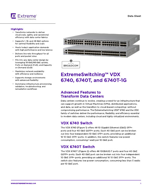
The VDX 674 0 T-1G ( Fig ure 3) offers 4 8 10 0 0 BA SE-T p ort s and t w o 4 0 Gb E QSFP+ p ort s. Each 4 0 Gb E p ort can b e b roken out int o four ind ep end ent 10 Gb E SFP+ p ort s, p rovid ing an ad d it ional eig ht 10 Gb E SFP+ p ort s for up link. A ll 4 8 10 0 0 BA SE-T p ort s can b e up g rad ed t o 4 8 10 GBA SE-T p ort s via t he Cap acit y on Dem and (CoD) soft w are license. Tw o 4 0 Gb E p ort s are enab led as p art of t he b ase license. The ad d it ional t w o 4 0 Gb E p ort s can b e up g rad ed via t he Port s on Dem and ( PoD) soft w are license.
- Meet s t od ay?s ap p licat ion d em and s w it h high perform ance and low latency
- Delivers line-rate t hroughput for all p ort s and p acket sizes
Dat a Sheet
P_AIS告警
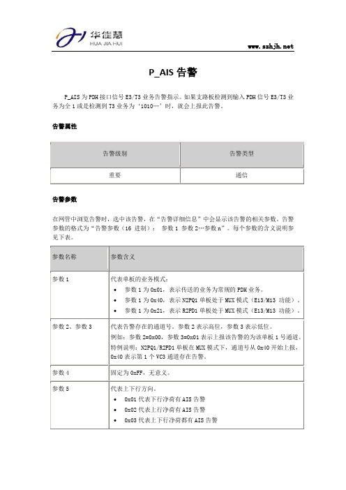
P_AIS告警P_AIS为PDH接口信号E3/T3业务告警指示。
如果支路板检测到输入PDH信号E3/T3业务为全1或是检测到T3业务为‘1010…’时,就会上报此告警。
告警属性告警参数在网管中浏览告警时,选中该告警,在“告警详细信息”中会显示该告警的相关参数。
告警参数的格式为“告警参数(16 进制):参数1 参数2…参数n”。
每个参数的含义说明参见下表。
对系统的影响该告警产生后,会造成PDH信号E3/T3业务的净荷有AIS告警,E3/T3业务不可用。
可能原因告警P_AIS产生的可能原因如下:∙单板对应通道有TU_AIS、TU_LOP告警。
∙传输线路故障。
∙对端站PDH设备输出AIS信号。
处理步骤1.在网管上查看该告警,根据告警参数确定产生该告警的通道号。
2.检查上报该通道是否有TU_AIS、TU_LOP告警存在,消除TU_AIS、TU_LOP告警后,查看本告警是否消除。
3.若告警未消除,请在DDF架处对告警通道的业务自环(硬件内环回)。
注意:环回操作会导致业务中断。
∙若告警消除,表示对端站设备故障,排除对端站设备故障后,查看本告警是否消除。
∙若告警未消除,请进行下一步操作。
4.请在接口板处对该通道进行自环(硬件内环回)。
注意:环回操作会导致业务中断。
∙若告警未消除,表示信号电缆连接故障,排除信号电缆连接故障后,查看告警是否消除。
∙若告警仍未消除,请进行下一步。
5.请在网管上对该通道进行内环回设置。
注意:环回操作会导致业务中断。
∙若告警消除,表示接口板故障,请重新插拔或更换接口板。
∙若告警未消除,则表示是单板故障,请更换上报告警的单板。
资料由深圳市华佳慧科技有限公司提供,转载请保留。
西子HAMCB(ALMCB)故障代码
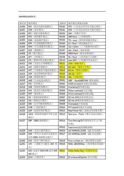
HAMCB/ALMCB板:模式码 操作模式 故障码操作模式或驱动故障AL000 EPC(紧急电源管制模式) ER100 DTC(门在设定时间内不能关到位) AL001 COR(复位模式) ER101 DTO(门在设定时间内不能开到位) AL002 EFS(消防员服务模式) ER102 NAV(电梯不可用)AL003 EFO(消防操作模式) ER103 DBP‐Fault(门旁路故障)AL004 EQO(地震操作模式) ER104 TCI – Lock(轿顶检修激活锁定)AL005 EPR(应急救援操作模式) ER105 LS – Fault(强迫减速丢失)AL006 EPW(应急救援等待模式) ER106 1LS + 2LSon(上下强减同时动作)AL007 OLD(超载模式) ER107 Adr.‐ Check(地址检测)AL008 ISC(独立模式) ER108 DBSS‐Fault(驱动未准备好)AL009 ATT(司机模式) ER109 SE – Fault(主机热敏开关故障)AL010 CTL(轿厢至特定楼层模式) ER110 start DCS!(门检测序列未运行)AL011 CHC(关闭大厅呼梯模式) ER111 UCM(UCM保护)AL012 LNS(满载直驶模式) ER112 Brk warn(抱闸力告警)AL013 MIT(中度载客交通流量模式)ER113 Brk err(抱闸力故障)AL014 DCP(延迟轿厢保护模式) ER115 Car slip(悬停)AL015 ANS(防捣乱模式) ER116 DBL(门锁短接)AL016 ARD(自动返基站模式) ER301 IGBT Fault(IGBT/IPM 模块故障)AL017 PKS(驻停模式) ER302 OVER Current(驱动器过流故障)AL018 GCB(按钮控制模式) ER304 Overtemp(散热器过温)AL019 EHS(紧急医用服务模式) ER305 Motor overload(马达过载)AL020 ROT(骚乱模式) ER306 Drive overload(驱动器过载)AL021 INI(系统初始化模式) ER307 DC link OVT(直流母线过压)AL022 INS(检修运行模式) ER308 DC link UVT(直流母线欠压)AL023 ESB(安全回路故障模式) ER309 Overspeed(主机超速)AL024 DHB(门保持模式) ER310 PVT lost(编码器丢失故障)AL025 ACP(防犯罪保护模式) ER312 Read Power Fail(底座功率读取失败)ER313 Task orun(Pwm中断任务执行超时)AL026 WCO(轿厢野蛮操作外呼无效模式)AL027 DBF(DBSS故障模式) ER314 Tune Moving(编码器角度自学习主机位移)ER315 Track error(速度跟随故障)AL028 SHO(安息日操作模式) ER316 1LV NORMAL CLOSE(1LV光电故障) AL029 DAR(带有自动返回至最低停ER317 2LV NORMAL CLOSE(2LV光电故障) 层的DBSS故障模式液压)AL030 DCS(检查门顺序模式) ER318 Floor number err(楼层数错误故障)ER319 PARA. ABNORMAL(主机参数设置故障)AL031 UFS(上极限开关触发DS3模式)AL032 ACC(加速至NOM SPE或者SHRER321 Motor Brake Slip(主机抱闸滑动) SPE模式)AL033 DLM(门锁异常) ER325 E2 write err(Eeprom读写出错)AL034 WDP(防水功能) ER326 Mtrthermlcntct(马达热继电器动作)AL035 MOT(下高峰) ER328 Brake dropped(抱闸开关1 检测故障) ER329 AC Line imbal(三相输出电流不平衡) ER330 AC Line UVT(三相输入电源欠压)ER331 Brake Unit Fault(制动单元故障)ER332 Thyristor module(晶闸管反馈故障)ER333 DBD PICKUP(主接触器或抱闸接触器动作故障)ER334 DDP Fault(设定时间内未检测到光电) ER335 Brake dropped 2(抱闸开关2 检测故障)ER342 Inv Ix Offst(U相电流采样故障)ER343 InvIyOffst(V相电流采样故障)ER344 InvIzOffst(W相电流采样故障)ER345 Brake Test Warn(抱闸力告警)ER346 Brake Test Errort(抱闸力故障)ER347 Base AD Offst(0.5V/1.5V基准电压故障)ER348 ETSC relay fault(ETSC接触器动作故障) ER361 Vcode abnormal 1(V码1故障)ER362 Vcode abnormal 2(V码2故障)ER363 Power Lost(主电源丢失)。
常用告警说明诺西

常用告警说明诺西诺西是一款广泛使用的告警系统,帮助企业实时监控和管理各种运行时异常和故障。
本文将介绍一些常见的告警类型以及相应的解决方案,以帮助用户更好地理解和处理诺西告警。
一、服务器宕机告警当服务器宕机时,会触发服务器宕机告警。
这可能是由于硬件故障、网络故障或者服务器过载等原因导致的。
处理服务器宕机告警的解决方案如下:1. 检查服务器硬件:首先需要确认服务器是否存在硬件故障。
可以检查服务器的电源、硬盘、内存等组件是否正常。
2. 检查网络连接:如果服务器宕机是由于网络故障导致的,需要检查网络连接是否正常。
可以尝试重新连接网络或者检查网络设备是否工作正常。
3. 调整服务器负载:如果服务器宕机是由于过载导致的,可以尝试通过减少服务器负载来解决。
例如,优化代码、增加服务器资源等。
二、磁盘空间告警磁盘空间告警是指服务器磁盘空间不足导致的告警。
这可能是由于长时间未清理无用文件、磁盘写入速度过快等原因导致的。
处理磁盘空间告警的解决方案如下:1. 清理无用文件:可以通过删除无用的日志文件、临时文件等来释放磁盘空间。
2. 增加磁盘容量:如果磁盘空间经常不足,可以考虑增加服务器的磁盘容量。
3. 优化磁盘写入速度:如果磁盘空间告警是由于磁盘写入速度过快导致的,可以尝试优化代码,减少磁盘写入次数。
三、CPU负载告警CPU负载告警是指服务器CPU负载过高导致的告警。
这可能是由于程序运行过多、代码不优化等原因导致的。
处理CPU负载告警的解决方案如下:1. 优化代码:可以通过优化代码、减少CPU消耗来降低CPU负载。
例如,减少循环次数、合并重复代码等。
2. 增加服务器资源:如果CPU负载经常超过服务器承受范围,可以考虑增加服务器资源。
例如,增加CPU核心数、内存容量等。
3. 分离任务:如果程序运行过多导致CPU负载过高,可以尝试将任务分离到多台服务器上进行处理,从而分担负载。
四、网络连接异常告警网络连接异常告警是指服务器与外部网络连接不稳定或者中断导致的告警。
海康威视DVR设备操作手册说明书
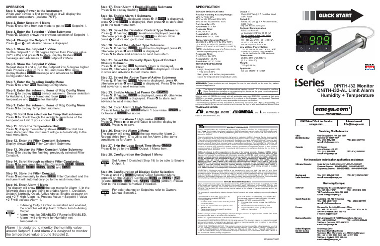
Step 17. Enter Alarm 1 Enable/Disable Submenu Press d to display flashing DSBL / ENBL .Step 18. Enable Alarm 1 SubmenuIf flashing ENBL is displayed, press a , if DSBL is displayed,press b until ENBL is displayed, then press d to store and go to the next menu item.Step 19. Select the Deviation Control Type Submenu Press d . If flashing _DEV Deviation is displayed press a ,otherwise press b until flashing _DEV is shown. Now press d to store and go to next menu item.Step 20. Select the Latched Type SubmenuPress d . If flashing UNLT Unlatched is displayed press a ,otherwise press b until UNLT is displayed.Press d to store and advance to next menu item.Step 21. Select the Normally Open Type of Contact Closure SubmenuPress d . If flashing N.o.Normally Open is displayed,press a , otherwise press b until N.o.is displayed. Press d to store and advance to next menu item.Step 22. Select the Above Type of Active Submenu Press d . If flashing ABoV Above is displayed, press a ,otherwise press b until ABoV is displayed. Press d to store and advance to next menu item.Step 23. Enable Alarm 1 at Power On (A.P.oN )Press d . If flashing ENBL is displayed, press a , otherwise press b until ENBL is displayed. Press d to store and advance to next menu item.Step 24. Enter Alarm 1 High SubmenuPress a twice to skip ALR.L Alarm 1 Low value. ALR.L is for below & ALR.H for above.Step 25. Set the Alarm 1 High value (ALR.H )Press d . Press b or c until value to set the display to 002.0. Press d to save.Step 26. Enter the Alarm 2 MenuThe display will show ALR2the top menu for Alarm 2.Repeat steps from 17 to 25 to set for Alarm 2 the same conditions as for Alarm 1.Step 27. Skip the Loop Break Time Menu (LOOP )Press a to go to the OUT1Output 1 Menu item.Step 28. Configuration the Output 1 MenuSet Alarm 1 Disabled (Step 18) to be able to Enable Output 1.Step 29. Configuration of Display Color Selection Press a until the COLR Display Color Selection Menu appears on the Display. Configure COLR as N.CLR /GRN (green), 1.CLR / RED (red), 2.CLR /AMBR (amber). Please refer to the operator’s manual if needed.For color change on Setpoints refer to Owners Manual Section 2.MQS4007/0411SPECIFICATIONSENSOR SPECIFICATIONSRelative Humidity Accuracy/Range:±2% for 10 to 90%±3% for 5 to 10% and 90 to 95%±4% for 0 to 5% and 95 to 100%Non-linearity : ±3%Hysteresis: ±1% RH Response Time :8 sec, tau 63%Repeatability : ±0.1%Resolution : 0.1%, 12bitTemperature Accuracy/Range*:±0.5°C for 5 to 45°C (±1°F for 41 to 113°F); up to ±1.5°C for -40 to 5°C and 45 to 124°C (up to ±2.7°F for -40 to 41°F and 113 to 257°F)*NOTE:extended temp range is for Probe only, the Controller’s operating temp is 0-50°CResponse Time : 5 to 30 sec, tau 63%Repeatability : ±0.1°C Resolution : 0.1°C, 14 bit METER SPECIFICATIONS Display:4-digit, 9-segment LED, •10.2 mm (0.40")Red, green, and amber programmable colors for setpoint and temperature units.Output 1†:Relay 250 Vac @ 3 A Resistive Load,SSR, Pulse Output 2†:Relay 250 Vac @ 3 A Resistive Load,SSR, Pulse †Only with -AL Limit Alarm optionOptions:Communication RS-232 / RS-485or Excitation:24 Vdc @ 25 mAExc. not available for Low Power OptionLine Voltage/Power:90 - 240 Vac ±10%,50 - 400 Hz*, or 110 - 375 Vdc, 4 W* No CE compliance above 60 HzLow Voltage Power Option:12 - 36 Vdc or 24 Vac** ±10%, 3 W**Units can be powered safely with 24 Vac but No Certification for CE/UL are claimed.Dimensions:25.4 H x 48 W x 126.3 D mm (1.0 x 1.89 x 5")Weight:127 g (0.28 lb)Approvals:CE per EN61010-1:2001It is the policy of OMEGA to comply with all worldwide safety and EMC/EMI regulations that apply.OEMGA is constantly pursuing certification of its products to the European New Approach Directives.OMEGA will add the CE mark to every appropriate device upon certification.The information contained in this document is believed to be correct, but OMEGA Engineering,Inc.accepts no liability for any errors it contains, and reserves the right to alter specifications without notice.TRADEMARK NOTICE:®,®,, andare Trademarks ofOMEGA ENGINEERING, INC.®This Quick Start Reference provides informationon setting up your instrument for basic operation.The latest complete Communication and OperationalManual as well as free Software and ActiveX Controlsare available at /specs/iseriesor on the CD-ROM enclosed with your shipment. SAFETY CONSIDERATIONThe instrument is a panel mount device protected in accordance with EN61010-1:2001. Remember that the unit has no power-on switch. Building installation should include a switch or circuit-breaker that must be compliant to IEC 947-1 and 947-3.SAFETY:•Do not exceed voltage rating on the label located onthe top of the instrument housing.•Always disconnect power before changing signal andpower connections.•Do not use this instrument on a work bench withoutits case for safety reasons.•Do not operate this instrument in flammable orexplosive atmospheres.•Do not expose this instrument to rain or moisture. EMC:•Whenever EMC is an issue, always use shielded cables.•Never run signal and power wires in the same conduit.•Use signal wire connections with twisted-pair cables.•Install Ferrite Bead(s) on signal wire close to theinstrument if EMC problems persist.MOUNTINGPanel Mounting Instruction:ing the dimensions from the panel cutout diagramshown above, cut an opening in the panel.2.Insert the unit into the opening from the front of thepanel, so the gasket seals between the bezel and thefront of the panel.3.Slide the retainer over the rear of the case and tightenagainst the backside of the mounting panel.。
Dupline 字段总线安装总线规格说明书
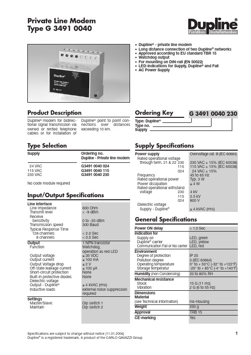
Du line®Input/Output Specifications•Dupline®- private line modem•Long distance connection of two Dupline®networks•Approved according to EU standard TBR 15•Watchdog output•For mounting on DIN-rail (EN 50022)•LED-indications for Supply, Dupline®and Fail•AC Power SupplyProduct DescriptionDupline® modem for bidirec-tional signal transmission viaowned or rented telephonecables or for installation ofDupline®point to point con-nections over distancesexceeding 10 km.Type Selection Supply SpecificationsSupply Ordering no.Dupline - Private line modem24 VAC G3491 0040 024115 VAC G3491 0040 115230 VAC G3491 0040 230No code module requiredPower supply Overvoltage cat. III (IEC 60664)Rated operational voltagethrough term. 21 & 22 230230 VAC ±15% (IEC 60038)115115 VAC ±15% (IEC 60038)02424 VAC ±15%Frequency45 to 65 HzRated operational power Typ. 3 WPower dissipation≤4 WRated operational withstandvoltage230 4 kV115 2.5 kV024800 VDielectric voltageSupply - Dupline®≥4 kVAC (rms) Private Line ModemType G 3491 0040General SpecificationsSpecifications are subject to change without notice (11.01.2006)1 Dupline®is a registered trademark. A product of the CARLO GAVAZZI GroupDu line®2Specifications are subject to change without notice (11.01.2006)Dupline ®is a registered trademark. A product of the CARLO GAVAZZI GroupWiring DiagramG 3491 0040Mode of OperationThe G 3491 0040 modems connect 2 Dupline ®systems via owned or rented tele-phone cables.T wo private line modems can be used to establish long distance connections betweentwo Dupline ®-systems. A G 3491 0040 must be installed at each end of the line and connected to the owned or leased wire and to the local Dupline ®network. In case of public telephone lines without the need for perma-nent connection, the D 9091modem interface are used together with commonly avail-able modems.G 3491 0040 converts all Dupline ®signals into standard FSK (frequency shift keying)tone signals. These signals can be transmitted via the telephone companies' stan-dard lines/ amplifiers. I n this way Dupline ®signals can be exchanged over very long dis-tances. I n most countries the telephone companies requireauthorization prior to connec-tion of the modem.Each of the Dupline ®instal-lations to be connected must have a channel generator coded for the same number of channels. Even so, one of the two modems is to be set up for master operation and the other one for slave operation (Dip switch 1).When two Dupline ®systems are connected in this way, all channels react as if it were one Dupline ®system. This means that activation of e.g.channel A1 in one system automatically causes channel A1 to be activated in the other system. The modem contains a watchdog output.Any interruption of the Dupline ®or private line leads to com-munication breakdown. As soon as the lines are reestab-lished, communication starts again automatically. The main-tain input is used to define the behaviour of the modem in case of a communication break-down. I f maintain is selected (Dip-Switch 2) the data of the last valid transmission is kept and the channels of the local Dupline ®are controlled accordingly. This conditionremains until communication is reestablished. I f the main-tain input is not activated, all channels controlled from the counterpart system are reset in case of communication break-down.Only two modems (a master and a slave) can be connect-ed to a telephone line. Several modems can, however, be connected to one Dupline ®system.Note : t is recommended to protect the modem by means of external transient protec-tion circuitry.G 3491 0040 also transmit analog values.G 3491 0040 cannot com-municate with FMX 1904.Dip-Switch SettingsSpecifications are subject to change without notice (11.01.2006)3Dupline ®is a registered trademark. A product of the CARLO GAVAZZI GroupDu line®G 3491 0040D I N-rail FMD 411For further information refer to "Accessories".Recommended types:#1 DEHN type VED#2 DEHN type ALE1212228262SupplyLineAccessoriesOperation DiagramRecommended Transient Protection S: signal wireDimensions (mm)。
linux 应急模式解决方法
linux 应急模式解决方法在Linux系统中,应急模式(Emergency Mode)通常是指系统无法正常启动或出现严重故障时的一种特殊模式。
在这种模式下,你可以通过命令行界面访问系统,并进行一些基本的维护操作。
以下是在Linux应急模式下解决问题的一些常见方法:1. 启动到恢复模式:在启动时按下相应的按键(通常是Shift键或Ctrl+Alt+F1~F6),进入恢复模式。
在恢复模式下,你可以使用root权限执行命令,并尝试修复系统。
2. 使用急救盘组(Boot/Root盘组):制作急救盘组:使用可启动的U盘或光盘,加载所需的系统文件和工具。
使用急救盘组启动系统,并进入急救模式。
在急救模式下,你可以使用root权限访问系统,并进行文件系统修复、系统配置等操作。
3. 查找和修复文件系统错误:使用`fsck`命令检查和修复文件系统错误。
例如,对于ext2/ext3/ext4文件系统,可以运行`fsck /dev/sdXY`(其中`sdXY`是你要检查的分区)。
如果文件系统存在错误,fsck可能会提示你进行修复。
根据提示操作即可。
4. 修复损坏的系统文件:如果系统文件损坏或丢失,你可以尝试从其他可用的源(如另一台机器上的相同版本的系统)复制相应的文件到受损系统上。
使用`rsync`命令或其他工具复制文件。
例如,使用`rsync -av /path/to/source/file /path/to/destination/file`命令复制文件。
5. 重新配置系统:如果系统配置文件被破坏或丢失,你可能需要手动编辑相应的配置文件来恢复它们。
使用文本编辑器(如vi、nano等)打开配置文件,并进行必要的修改和修复。
6. 重新安装系统:如果以上方法都无法解决问题,可能需要重新安装操作系统或重新配置系统环境。
在重新安装之前,确保备份重要数据,并确保所选的安装源是可靠的。
请注意,以上方法可能需要一定的Linux知识和经验才能有效执行。
迅达电梯5400超详细故障代码中文版
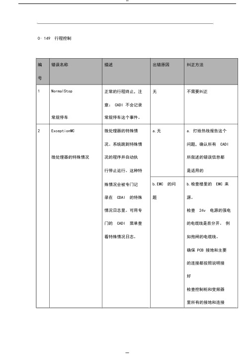
0⋯149 行程控制编错误名称描述出错原因纠正方法号1 NormalStop 正常的行程终止,注无不需要纠正意: CADI 不会记录常规停车常规停车这个事件。
2 ExceptionMC 微处理器的特殊情 a.无 a. 打给热线报告这个况。
系统跳到特殊情问题,确认所有 CADI 微处理器的特殊情况况的程序并自动执所叙述的错误信息都行停止运行。
这种特是适用的殊情况会被专门记 b.EMC 的问 b.检查楼里的 EMC 来录在 CDAI 的特殊题源。
情况日志里。
可用专检查 24v 电源的强电门的 CADI 菜单查的电缆线是否分开。
例看特殊情况日志。
如抱闸的电缆线。
确保 PCB 接地和主要的连接都按照说明接好检查控制柜和变频器里所有的接地和连接c. 有缺陷的 c.更换 PCB 板PCB 板3NoKSE_STDSTL 轿箱停在一个轴端 , a.错误的参数 a.检查轴端 KSE 磁开发觉 KSE 信号没有值关的物理位置是否和通讯到位置计算的参数 SHAFT_PARA ,距离编码器SHAFT_DISTANCE的值一致对应b.错误的磁极 b. 检查磁开关的极性 ,最低的 KSE 的磁开关是南极 ,下一个磁体 (间隙的最低磁极 )是北极 .上部最多的磁极是南极.c.KSE 开关 c.检查 KSE 开关 ,检查KSE 开关到 PCB 板的连接 .4InvldMovement 错误的移动。
当行程抱闸或抱闸检查抱闸的机械结构控制在停止相位时调节器坏了(抱闸调节器,抱闸轴轿箱被发现有移动。
(抱闸力矩套)当抱闸手动打开后不足够大来做实验检查抱闸是否轿箱发生移动,行程固定住轿箱)动作,当空轿箱全速上控制就能够察觉到行时,让它急停,看是移动。
否能停下来。
用抱闸测试来测量急停时的平均减速,还要注意可能是钢丝绳打滑。
5SH_on_STDSTL 接触器 SH,SH1 在检查 SH,SH1 无停止状态时吸合的的辅助接触器(RH 和RH1 ,如果安装的话)SH,SH1 被手动操作过6SB_on_STDSTL 接触器 SB 在停止状错误的反馈检查 SB 的辅助接触器态时吸合连接SB 被手动移动7SH_Fault SH, SH1 的辅助接 a.安全回路断 a.检查安全回路触器RH 和RH1在开轿箱移动时没吸合 b.错误的参数 b. 如果这个错误发生值在轿箱快接近目标楼层时,很可能是门的提前开门电路有问题,减小参数值MAX_DOOR_ZONEc.电缆线坏了 c.检查 SH,SH1 的辅助接触器的接线(RH,RH1 )8SB_Fault 当轿箱移动或抱闸安全回路断检查安全回路;模块上有错误时,开;SB 触点打开SB/SB1 触点检查 SB/SB1 触点的接不正常工作线和工作状态9KB_Fault 抱闸触点 KB /KB1 抱闸触点损检查抱闸,不正常开关,为了防坏;检查抱闸触点的调节。
诺西设备-告警管理对应表

TYPE CODE ALARMNotices0002OSI INCOMING CALL ROUTING FAILEDNotices0009OSI FORCED CONNECTION CLEARINGNotices0012X.25 CALL ESTABLISHMENT FAILEDNotices0013SAME SERVICE ALREADY IN NAMETA-BLE WITH DIFFERENT PARAMETERSNotices0015AUTOMATIC RETURN ON RESTARTFAILURE ALLOWEDNotices0016SIGNALLING LINK CONGESTION LEVEL EXCEEDEDNotices0017DATABASE INTEGRITY CHECKING COMPLETEDNotices0018DATABASE RECOVERY IS IN PROGRESSNotices0020AUTOMATIC RETURN AFTER TIMEPERIOD ALLOWEDNotices0021CONVERSION COMPLETED SUCCESS-FULLYNotices0026SIGNALLING LINK LOAD OVER THRESHOLDNotices0027SOFTWARE PACKAGE FALLBACK COPYING NOTICENotices0032FILE SYSTEM NOTIFICATIONNotices0033FILE UPDATES TO DISK PREVENTEDNotices0036FILE UPDATES TO DISK RESUMEDNotices0037PASSIVE WARMING IN USENotices0048SEMIPERMANENT CONNECTION MISSINGNotices0061CIRCUIT GROUPS HAVE BEEN UPDATEDNotices0070SIGNALLING LINK REMOTE INHIBITEDNotices0071SIGNALLING LINK REMOTE UNINHIB-ITEDNotices0072SIGNALLING LINK REMOTE BLOCKEDNotices0073SIGNALLING LINK REMOTE UNBLOCKEDNotices0074REPEATED CHANGEBACK DECLARA-TION NOT ACKNOWLEDGEDNotices0075SIGNALLING LINK FORCED UNINHIBIT-ING NOT POSSIBLENotices0088ETHERNET INTERFACE SWITCHOVER EXECUTEDNotices0090IP ADDRESS FOR HOT BILLING DATACHANGEDNotices0101SDH PROTECTION SWITCHING EXECUTEDNotices0104SGSN ENDPOINT CREATED Notices0105SGSN ENDPOINT ADDED Notices0106SGSN ENDPOINT DELETEDNotices0116LOGGING OF SERVICE TERMINAL COMMANDS IS OFFNotices0125PCU PROCESSOR LOAD HIGH Notices0132CIRCUIT BARREDNotices0133CIRCUIT DEBARREDNotices0136PCU CONNECTIVITY EXCEEDEDNotices0143IPSEC: AUTOMATIC CERTIFICATE ENROLLMENT SUCCESSFULLNotices0240COORDINATED STATE CHANGE NOTICENotices0270DEFAULT PACKAGE NOTICE Notices0421UNIT TIME UPDATED Notices0422TIME UPDATEDNotices0430MML-SESSION ANNOUNCEMENTNotices0554RADIO NETWORK SUPERVISION MEA-SUREMENT PERIOD CHANGEDNotices0590PROCESSING OF ALARMS IS STARTEDANEWNotices0599HEARTBEAT NOTICE FOR ALARM FLOW SUPERVISIONNotices0630SYNCHRONIZATION SIGNAL CHANGEDNotices0660DATABASE TRANSACTIONS OR DISKUPDATES PREVENTEDNotices0661DATABASE FILE FILL RATIO EXCEEDSTHE ALARM LIMITNotices0689SYSTEM RESTARTEDNotices0690WORKING STATE CHANGE Notices0691AUTOMATIC RECOVERY ACTION Notices0697UNEXPECTED SWITCHOVERNotices0800O&M CHANNEL CHANGED TO ALTER-NATIVE CONNECTIONNotices0801MTU ADDRESSES MISSING OR INCOR-RECTNotices0804COMMAND CALENDAR DISK INTER-FACE NOTICENotices0814ADMINISTRATIVE USER HAS LOGGEDINTO NETWORK ELEMENTNotices0860DISK NOTICENotices0890Q3 ALARM UPLOAD REQUIREDNotices0930TCSM SYNCHRONISATION SIGNALCHANGEDDisturbance Printouts1001UNIT RESTARTED Disturbance Printouts1002RAM FAILURE Disturbance Printouts1003PARITY ERROR IN RAMDisturbance Printouts1004COMMUNICATION ERROR BETWEEN PROGRAM BLOCKSDisturbance Printouts1005PLUG-IN UNIT RESTARTED Disturbance Printouts1007RESTARTED PROGRAM BLOCK Disturbance Printouts1008MML PROGRAM RESTARTEDDisturbance Printouts1010NO RESPONSE TO UNIT SUPERVISION MESSAGEDisturbance Printouts1012EXCESSIVE RESTARTS OF UNITDisturbance Printouts1014PROCESSOR LOAD RATE ALARM LIMIT EXCEEDEDDisturbance Printouts1015OPERATING SYSTEM ERROR COUNTER INCREASEDDisturbance Printouts1016MB INTERFACE FAILUREDisturbance Printouts1018PROGRAM BLOCK COMMUNICATION ERRORDisturbance Printouts1019PROGRAM BLOCK ACTION FAILUREDisturbance Printouts1020PROGRAM BLOCK START UP FAILUREDisturbance Printouts1021PROGRAM BLOCK REWARMING STARTEDDisturbance Printouts1022PROGRAM BLOCK WARMUP FAILUREDisturbance Printouts1023EXCESSIVE DISTURBANCES IN SUPERVISIONDisturbance Printouts1024HAND PROCESS ERROR IN PROGRAM BLOCKDisturbance Printouts1028RESTARTED PROGRAM BLOCK IN PREPROCESSOR UNITDisturbance Printouts1029SCCP STP MESSAGE PREVENTIONDisturbance Printouts1033OSI CLNS CONFIGURATION FAILEDDisturbance Printouts1034MAXIMUM SEQUENCE NUMBER OF OSI CLNS EXCEEDEDDisturbance Printouts1035UPU MESSAGE RECEIVEDDisturbance Printouts1044ERROR IN SWITCH COMPARE TESTDisturbance Printouts1045ERROR BETWEEN MARKER TABLES AND SWITCH CONTROL MEMORYDisturbance Printouts1047NO RESPONSE FROM CONTROLLER OF SWITCHING NETWORKDisturbance Printouts1048CONTROLLER OF SWITCHING NETWORK RESTARTEDDisturbance Printouts1049SEMIPERMANENT MULTICHANNEL CONNECTION MISSINGDisturbance Printouts1055TCAP TRANSACTION FAILUREDisturbance Printouts1056MESSAGE FROM NETWORK TO UNKNOWN SUBSYSTEMDisturbance Printouts1058ERROR IN SMUX PLUG-IN UNITDisturbance Printouts1061ERROR IN SWITCH COMPARE TESTDisturbance Printouts1062ERROR BETWEEN MARKER TABLES AND SWITCH CONTROL MEMORYDisturbance Printouts1064UNIT UPDATE FAILURE Disturbance Printouts1065DISK UPDATE FAILUREDisturbance Printouts1070CCS7 PROGRAM BLOCK DATA ERRORDisturbance Printouts1071PROCESSOR TIME SHORTAGEDisturbance Printouts1072SIGNALLING LINK OUT OF SERVICEDisturbance Printouts1076FORCED LIGHTWEIGHT SCHEDULINGDisturbance Printouts1077FREE STACK SIZE BELOW LIMITDisturbance Printouts1078PROCESS EXCEPTION Disturbance Printouts1080PROCESS STOPPED Disturbance Printouts1082HAND USAGE LIMIT EXCEEDED Disturbance Printouts1083SEMAPHORE USE ERRORDisturbance Printouts1089DYNAMIC LDT SLOTS EXHAUSTEDDisturbance Printouts1090BUFFER HANDLE ERRORDisturbance Printouts1092COMMUNICATION FAILURE IN FIELD REPORTINGDisturbance Printouts1093OUTPUT FAILURE IN FIELD REPORTINGDisturbance Printouts1095TRAFFIC MEASUREMENT OUTPUT FAILUREDisturbance Printouts1098TOO LONG MESSAGEDisturbance Printouts1103SIGNALLING MEASUREMENT REPORT LOSTDisturbance Printouts1105LINE SIGNALLING RECEIVE OVERLOADDisturbance Printouts1125TRIAL CONFIGURATION DELETEDDisturbance Printouts1128EXCESSIVE DISTURBANCES IN FILE LOADINGDisturbance Printouts1136SIGNALLING MESSAGE DISTRIBUTION ERRORDisturbance Printouts1137INCORRECT SIGNALLING MESSAGE FROM SIGNALLING TERMINALDisturbance Printouts1140FREE LDT SLOT COUNT BELOW LIMITDisturbance Printouts1141DELAY BUFFER OVERFLOW IN SIGNALLING TERMINALDisturbance Printouts1142FAMILY MEMORY USAGE SUPERVISION LIMIT EXCEEDEDDisturbance Printouts1143AMOUNT OF FREE MEMORY REDUCEDDisturbance Printouts1144FREE BUFFER HEADERS EXHAUSTINGDisturbance Printouts1147MESSAGE QUEUE OVERFLOW Disturbance Printouts1148EXCESSIVE TRAPSDisturbance Printouts1162FILE SYSTEM COMMUNICATION ERRORDisturbance Printouts1165BUFFER ALLOCATION FAILEDDisturbance Printouts1169FREEZING PERIOD OF SS7 REPORTING LOSTDisturbance Printouts1178PREPROCESSOR UNIT DISTURBANCEDisturbance Printouts1182PREPROCESSOR UNIT RESTARTEDDisturbance Printouts1190EXCESSIVE ERRORS IN SCPDisturbance Printouts1200ACTOR HAS FAILED TO REGISTER TO THE SUPERVISIONDisturbance Printouts1204WATCHDOG CAUSES UNIT RESTARTDisturbance Printouts1207UNITS WORKING STATE DATA CORRUPTED IN THE SYSTEMDisturbance Printouts1210PHASE ADVANCE OF TIMING SIGNAL CHANGEDDisturbance Printouts1220HANDLING OF MEASUREMENT DEFINITION FILE FAILEDDisturbance Printouts1221STATISTICAL MEASUREMENT REPORT OUTPUT FAILEDDisturbance Printouts1222DATA WRITING VIA VDS DEVICE FAILEDDisturbance Printouts1228UNIT SUPERVISION NOT FUNCTIONINGDisturbance Printouts1234UPDATE OF PASSWORD VALIDITY TIME FAILEDDisturbance Printouts1240SCCP DISTURBANCEDisturbance Printouts1241SCCP GLOBAL TITLE TRANSLATION ANALYSIS FILE ERRORDisturbance Printouts1242SCCP GLOBAL TITLE TRANSLATION RESULT FILE ERRORDisturbance Printouts1244RUNNING OUT OF MESSAGE BUFFERSDisturbance Printouts1249DATABASE DISK COPY HAS EXCEEDED MAXIMUM ALLOWED AGEDisturbance Printouts1250DATA LINK LAYER PROTOCOL MISMATCHDisturbance Printouts1251EXCESSIVE RETRANSMISSIONS ON DATA LINK CONNECTIONDisturbance Printouts1252EXCESSIVE ERROR RATE ON DATA LINK CONNECTIONDisturbance Printouts1253NO RESPONSE FROM PRIMARY RATE ACCESS TERMINALDisturbance Printouts1254UNSOLICITED DATA LINK RE-ESTABLISHMENTDisturbance Printouts1255PRIMARY RATE ACCESS MESSAGE DISTRIBUTION ERRORDisturbance Printouts1256INCORRECT PRD MESSAGE FROM PRIMARY RATE ACCESS TERMINALDisturbance Printouts1260X.25/ETHERNET DATA TERMINAL SPONTANEOUS RESTARTDisturbance Printouts1261OSI CHANNEL GROUP UNREACHABLEDisturbance Printouts1262OSI SERVICE PROVIDER RESETDisturbance Printouts1263OSI SERVICE PROVIDER INTERFACE ERRORDisturbance Printouts1264OSI INCOMING CALL DENIED Disturbance Printouts1273ASP ACTIVATION FAILEDDisturbance Printouts1280INTERNAL COMMUNICATION CHANNEL FAILUREDisturbance Printouts1282ASSOCIATION PARAMETER FAILUREDisturbance Printouts1293SCCP GT SCREENING APPLIEDDisturbance Printouts1300SUPERVISION CONNECTION TO UNIT LOSTDisturbance Printouts1301PCU DIGITAL SIGNAL PROCESSOR RESTARTDisturbance Printouts1302PAGING OVERLOAD Disturbance Printouts1339ACTIVE FRAMER UNIT FAILURE Disturbance Printouts1340HOTLINK FAILUREDisturbance Printouts1347CS PAGING COORDINATION ACTIVATION/DEACTIVATION FAILEDDisturbance Printouts1400AFS RESTARTEDDisturbance Printouts1423NO RESPONSE FROM MAIN CLOCKDisturbance Printouts1425OVERFLOW IN ALARM BUFFERINGDisturbance Printouts1431MMI SYSTEM OVERLOADDisturbance Printouts1432DISTURBANCE IN COMMAND CALENDARDisturbance Printouts1548MTP CONFUSION MESSAGE RECEIVEDDisturbance Printouts1557EVENT HANDLER CANNOT WORK PROPERLY DUE TO SERVICE FAILUREDisturbance Printouts1569CRITICAL LIMIT IN SECURITY REPORTING REACHEDDisturbance Printouts1570SECURITY LOG ALARM LIMIT REACHEDDisturbance Printouts1578CONFUSION IN BSSMAP SIGNALINGDisturbance Printouts1580GLOBAL RESET FAILUREDisturbance Printouts1582CONNECTION OR RELEASE ERRORDisturbance Printouts1583LAPD MSG DISTRIBUTION PROBLEMDisturbance Printouts1585ABNORMAL A INTERFACE CIRCUIT RELEASEDisturbance Printouts1590ALARM SYSTEM MESSAGE SENDING BUFFER FULLDisturbance Printouts1597I/O DEVICE FOUND FAULTY BY ALARM SYSTEMDisturbance Printouts1598UNIT FOUND FAULTY BY ALARM SYSTEMDisturbance Printouts1623ERROR DURING SUPERVISIONDisturbance Printouts1630RAM FAILURE IN SYNCHRONIZATION UNITDisturbance Printouts1660UPDATE NUMBER MISMATCHDisturbance Printouts1661DATABASE MANAGER IN FATAL ERROR STATEDisturbance Printouts1662DATABASE LOADING ERRORDisturbance Printouts1663HAND RESERVATION ERROR IN DATABASE MANAGERDisturbance Printouts1682SCDFLE UPDATE FAILURE Disturbance Printouts1683FAULTY UNIT SP-EX Disturbance Printouts1684SPARE UNIT WARMUP FAILURE Disturbance Printouts1685UNIT RESTART FAILURE Disturbance Printouts1687RECOVERY ACTION FAILURE Disturbance Printouts1688FAILURE IN CALL CLEARING Disturbance Printouts1800SCSI ADDRESS ILLEGALDisturbance Printouts1801MASS MEMORY FILE BACKUP FAILUREDisturbance Printouts1802BACKUP COPY LOG FAILUREDisturbance Printouts1804IP ROUTING RESOURCE SHORTAGEDisturbance Printouts1806PRINTER SPOOLER DISABLEDDisturbance Printouts1809IP CONFIGURATION INQUIRY SERVICE FAILEDDisturbance Printouts1850BTS TEST REPORT PRINTOUT FAILEDDisturbance Printouts1860DISK DISTURBANCE Disturbance Printouts1881TAPI FAILURE Disturbance Printouts1882DMADI FAILURE Disturbance Printouts1884LABEL PARAMETER FAILUREDisturbance Printouts1885ERROR IN WRITING DATA TO MAGNETIC TAPEDisturbance Printouts1886ERROR IN TAPE OPERATION Disturbance Printouts1887BLOCK COUNTER FAILURE Disturbance Printouts1891AS7 RESTARTEDDisturbance Printouts1893O&M CHANNEL SEND OVERLOADDisturbance Printouts1894NO RESPONSE TO AS7 SUPERVISION MESSAGEDisturbance Printouts1895DISTURBANCE IN O&M CHANNEL Disturbance Printouts1900DEGRADED SLIP FREQUENCY Disturbance Printouts1901ET RESTARTEDDisturbance Printouts1910COMMUNICATION FAILURE WITH TRXDisturbance Printouts1911INVALID URGENCY LEVEL IN TRANSMISSION ALARMDisturbance Printouts1915TCSM CLOCK DISTURBANCE Failure Printouts2002FILE SPACE ERROR Failure Printouts2004FILE BACKUP FAILUREFailure Printouts2005CHECKSUM ERROR IN LOAD MODULEFailure Printouts2006FILE UPDATING SYSTEM DATA CORRUPTEDFailure Printouts2007FILE UPDATING ON AUXILI ARY STORAGE IS NOT PROCEEDINGFailure Printouts2008ERROR IN FILE INITIALIZATIONFailure Printouts2009ERROR IN USING PRFILEFailure Printouts2010FILE CHAINING ERROR Failure Printouts2012ERROR IN FILE OPENING Failure Printouts2013MODULE STRUCTURE FAULTYFailure Printouts2014EXCESSIVE ERRORS IN FILE TRANSFER PROCESSFailure Printouts2015MB COMMUNICATION ERROR Failure Printouts2017FILE DISTRIBUTION ERRORFailure Printouts2018OVERFLOW IN HANDLING ALARM EVENTSFailure Printouts2022CLOCK BUFFER ALARM Failure Printouts2023MAIN CLOCK FAILUREFailure Printouts2024MAIN CLOCK NEEDS ADJUSTMENTFailure Printouts2025MAIN CLOCK SYNCHRONIZATION SIGNAL MISSINGFailure Printouts2026MAIN CLOCK SYNCHRONIZATION SIGNAL MISSINGFailure Printouts2027MAIN CLOCK SYNCHRONIZATION SIGNAL MISSINGFailure Printouts2028MAIN CLOCK MANUAL CONTROLFailure Printouts2029MAIN CLOCK FAILURE Failure Printouts2031MB CLOCK FAILURE Failure Printouts2033GSW CLOCK FAILURE Failure Printouts2039ET CLOCK FAILURE Failure Printouts2040TG FAILUREFailure Printouts2041EXCESSIVE ERRORS IN SWITCHINGFailure Printouts2043EXCESSIVE ERRORS IN SWITCH TESTING MODULEFailure Printouts2044EXCESSIVE ERRORS IN SWITCH COMPARE TESTFailure Printouts2045EXCESSIVE ERRORS BETWEEN MARKER TABLES AND SWITCH CONTROL MEMORYFailure Printouts2048FAILURE IN SEMIPERMANENT CONNECTIONFailure Printouts2050PLUG IN UNIT MISSING IN SWITCHING NETWORKFailure Printouts2051POWER FAILURE IN SWITCHING NETWORKFailure Printouts2052SWITCH CLOCK FAILUREFailure Printouts2053CHECKSUM ERROR IN SWCOP PROMFailure Printouts2054CHECKSUM ERROR IN BOOT PROMFailure Printouts2057TG FAILURE IN SYNCRONIZATION UNITFailure Printouts2058EXCESSIVE ERRORS IN SMUX PLUG-IN UNITFailure Printouts2060CENTRAL MEMORY FILE ERRORFailure Printouts2061CENTRAL MEMORY FILE SPACE RESERVEDFailure Printouts2062EXCESSIVE ERRORS IN CENTRAL MEMORY INCOMING DATAFailure Printouts2063DAY CLASS INQUIRY FOR TIME CONTROLLED ROUTING FAILEDFailure Printouts2064ROUTE SET UNAVAILABLE Failure Printouts2065FILE CONFLICT ERROR Failure Printouts2066FILE ADDRESSING ERROR Failure Printouts2068FILE DISTRIBUTION FAILUREFailure Printouts2069SIGNALLING LINK TEST FAILEDFailure Printouts2070LINK SET UNAVAILABLEFailure Printouts2071SIGNALLING LINK TERMINAL FAULTYFailure Printouts2072FAILURE IN SIGNALLING LINK ACTIVATION OR RESTORATIONFailure Printouts2073UPDATE FAILURE IN SPARE CCS7 PROGRAM BLOCKFailure Printouts2074WARM-UP FAILURE IN SPARE CCS7 PROGRAM BLOCKFailure Printouts2075COMMUNICATION FAILURE BET WEEN SIGNALLING TERMINAL AND CCNETMFailure Printouts2076SS7 UNIT UPDATE FAILUREFailure Printouts2077CCS7 PROGRAM BLOCK DATA FAILUREFailure Printouts2078SS7 UNIT CHANGE FAILUREFailure Printouts2079LOOP TEST FAILED IN SIGNALLING LINK TERMINALFailure Printouts2087LOW TRAFFIC CAPACITY ON CIRCUIT GROUPFailure Printouts2094WARM-UP FAILURE IN ACTIVE CCS7 PROGRAM BLOCKFailure Printouts2114FR VIRTUAL CONNECTION FAILEDFailure Printouts2115FR USER LINK INTEGRITY VERIFICATION FAILEDFailure Printouts2129NO FREE BUFFERS Failure Printouts2131ERROR IN CCS FILEFailure Printouts2132FILE POINTER INITIALIZATION ERRORFailure Printouts2133SEND BUFFER OVERFLOW IN SIGNALLING TERMINALFailure Printouts2134WARM-UP ERROR IN CCSEND PROGRAM BLOCKFailure Printouts2136CCS CIRCUIT RELEASING FAILUREFailure Printouts2137PLUG-IN UNIT LOCATION ERRORFailure Printouts2138PLUG-IN UNIT SOFTWARE PACKAGE CHECK SUM ERRORFailure Printouts2139PLUG-IN UNIT SOFTWARE PACKAGE LOAD FAILUREFailure Printouts2141PLUG-IN UNIT INITIALIZATION FAILUREFailure Printouts2142PLUG-IN UNIT SUPERVISION FAILUREFailure Printouts2145ERROR IN ASM COMPARE TEST Failure Printouts2146BUS FAILURE IN SWCOPFailure Printouts2160PREPROCESSOR UNIT RESTART FAILUREFailure Printouts2165EXCESSIVE REJECTIONS OF OSI CLNS PROTOCOL DATA UNITSFailure Printouts2166CORRUPTED OSI CLNS LINK STATE PROTOCOL DATA UNITFailure Printouts2167EXCESSIVE REJECTIONS OF OSI CLNS LINK STATE PDUFailure Printouts2168EXCESSIVE REJECTIONS OF OSI CLNS 9542 PDUSFailure Printouts2169OSI CLNS LINK STATE PDU LEVEL 1 DATABASE OVERLOADFailure Printouts2171NO USER FOR OSI CLNSFailure Printouts2174OSI CLNS SERVICE NOT AVAILABLEFailure Printouts2175OSI CLNS LINKAGE NOT AVAILABLEFailure Printouts2176NO CLNS OBJECT IN OSI DATABASE FOR INITIALIZATIONFailure Printouts2177DISCARDED MANUAL AREA ADDRESS OF OSI CLNSFailure Printouts2178MISMATCH OF MAXIMUM AREA ADDRESS OF OSI CLNSFailure Printouts2179INCOMPATIBLE PROTOCOL VERSIONS OF OSI CLNSFailure Printouts2181MISMATCH OF SYSTEM ID LENGTH OF OSI CLNSFailure Printouts2182MISMATCH OF AREA ADDRESS OF OSI CLNSFailure Printouts2183REJECTED OSI CLNS ADJACENCY DUE TO LACK OF RESOURCESFailure Printouts2184OSI CLNS MANAGEMENT INFORMATION CORRUPTEDFailure Printouts2185ROUTING OF OSI OUTGOING CALL FAILEDFailure Printouts2188FR ACCESS DATA UPDATING FAILEDFailure Printouts2189COMMUNICATION FAILURE BETWEEN FR TERMINAL AND FRCMANFailure Printouts2197NAMETABLE IS FULL Failure Printouts2200PCM LINE LOOPFailure Printouts2202ET FAILUREFailure Printouts2203AIS COMMAND ACK Failure Printouts2204EQUIPMENT LOOPFailure Printouts2205ET2 FAILUREFailure Printouts2224ERROR IN MSU HANDLINGFailure Printouts2226FILE CONFLICT DUE TO SWITCHOVERFailure Printouts2241SCCP SUBSYSTEM PROHIBITEDFailure Printouts2244UPDATE FAILURE IN SPARE UNITFailure Printouts2246SCCP ROUTING FAILUREFailure Printouts2247SS7 ERRONEOUS SIGNALLING MESSAGEFailure Printouts2248OPERATING SYSTEM RESOURCES ARE FAILINGFailure Printouts2249OPERATING SYSTEM RESOURCES HAVE FAILEDFailure Printouts2250FAILURE IN D-CHANNEL ACTIVATION OR RESTORATIONFailure Printouts2251ERROR IN PRIMARY RATE ACCESS FILEFailure Printouts2252LOOP TEST FAILED IN PRIMARY RATE ACCESS TERMINALFailure Printouts2254SCCP NOT DEFINED FOR NETWORKFailure Printouts2258HARDWARE ERROR OF ALARM LOGIC IN SWITCHING NETWORKFailure Printouts2259DATABASE IS INCONSISTENT Failure Printouts2260FILE UPDATING ERRORFailure Printouts2261CONFLICT BETWEEN TWO FILESFailure Printouts2262OSI SUBNETWORK INTERFACE OUT OF ORDERFailure Printouts2263OSI OUTGOING CALL FAILEDFailure Printouts2264OSI ADMINISTRATIVE FILES CORRUPTEDFailure Printouts2265OSI POSSIBLE SECURITY VIOLATIONFailure Printouts2267DATABASE INTEGRITY CHECKING FAILEDFailure Printouts2268DATABASE BACKUP PROCESS IS TERMINATEDFailure Printouts2269ERRONEOUS DISK CACHE SIZE Failure Printouts2271BOOT LOADING FAILED Failure Printouts2272BOOT LOADING ERRORFailure Printouts2273AUTOMATIC RETURN TO SPARE PACKAGEFailure Printouts2274SOMAFI ERRORFailure Printouts2275HARDWARE INTERFACE INITIALIZATION ERRORFailure Printouts2284ILLEGAL VALUE FOR STACK POINTERFailure Printouts2285SIGNALLING TERMINAL FAULTYFailure Printouts2293AUTOMATIC RETURN AFTER TIME PERIOD INITIATEDFailure Printouts2294UNCONTROLLED CHANGE OF DEFAULT PACKAGEFailure Printouts2295CONVERSION FAILUREFailure Printouts2332CIRCUITS BARRED IN D-CHANNELFailure Printouts2336ERROR IN INITIAL LOADINGFailure Printouts2337AUTOMATIC RETURN ON RESTART FAILURE IN FORCEFailure Printouts2339SP-CIC -> PCM-TSL CON VERSION TABLE UPDATE ERRORFailure Printouts2345UNAUTHORIZED STP ACCESSFailure Printouts2347POWER SUPPLY FAILURE IN CPUFailure Printouts2374FILE SPACE ERROR IN PREPROCESSOR UNITFailure Printouts2375DYNAMIC FLAGPOOL FULL IN PREPROCESSOR UNITFailure Printouts2376ALARM SYSTEM FILE ERRO R IN PREPROCESSOR UNITFailure Printouts2379VOLTAGE IN CLOCK CIRCUIT OF CPU HAS FAILEDFailure Printouts2380CPU TIME DIFFERS FROM CALENDAR TIMEFailure Printouts2381AMOUNT OF FREE MEMORY CRITICALLY REDUCEDFailure Printouts2383RBS DATA PATH CUT OFF Failure Printouts2384MEMORY USAGE OVERFLOWFailure Printouts2385SUPERVISION IN COMPUTER HAS STOPPEDFailure Printouts2386OVERWRITING UNTRANSFERRED VDS-DEVICE DATA FILEFailure Printouts2389WATCHDOG DISABLEDFailure Printouts2390EXTERNAL CLOCK SYNCHRONIZATION SIGNAL MISSINGFailure Printouts2391CPU TYPE DIFFERS FROM EQUIPMENTFailure Printouts2393FALLBACK COPYING TERMINATED IN ERRORFailure Printouts2394ERROR IN FINISHING FALLBACK COPYINGFailure Printouts2397DATABASE FILE IS IN DANGER TO GET FULLFailure Printouts2399DATABASE DISK UPDATES ARE PREVENTEDFailure Printouts2402AFS CONNECTION FAILURE Failure Printouts2403SERIAL CHANNEL FAILURE Failure Printouts2406AFS FAILUREFailure Printouts2410CONNECTION OF A CIRCUIT HAS FAILED IN THE SWITCHING NETWORKFailure Printouts2420TIMES DIFFER IN EXCHANGEFailure Printouts2424DISCREPANCY BETWEEN RECORD DATA AND BITMAPFailure Printouts2425ALARM SYSTEM FILE ERRORFailure Printouts2426CHECKSUM ERROR IN FILE BLOCKFailure Printouts2427MMI SYSTEM FILE ERROR Failure Printouts2430ERROR IN COMMAND CALENDAR Failure Printouts2431IOLOCO FILE ERRORFailure Printouts2433DISK FILE HANDLING ERRORFailure Printouts2435ERROR IN CREATING TEXT FILES FOR MMI SYSTEMFailure Printouts2437FILE SYSTEM DATA ERRORFailure Printouts2438HW ERROR DETECTED IN BOOT PHASEFailure Printouts2440UPDATE ERROR OF FILE SYSTEM CONTROL FILEFailure Printouts2441DISK UPDATE ERROR OF FILE SYSTEM CONTROL FILEFailure Printouts2445UNIT TYPE HAS NO REDUNDANCYFailure Printouts2447DATABASE TRANSACTION SAVING FAILEDFailure Printouts2454TIMES DIFFER IN NET Failure Printouts2455ISDN CALL FAILUREFailure Printouts2457ABIS LINK USER CONFIGURATION FAILUREFailure Printouts2458DECODING OF MESSAGE FAILSFailure Printouts2459ABIS SETUP FAILURE OCCURRENCEFailure Printouts2460OVERFLOW IN FILE OF ACTIVE BTS ALARMSFailure Printouts2461OVERFLOW IN LIST OF ACTIVE ALARMS OF BCFFailure Printouts2463BTS ALARM SYSTEM OUTPUT BUFFER OVERFLOWFailure Printouts2469STORING OF CHARGING DATA NOT COMPLETED ON ALL DEVICESFailure Printouts2471RADIO NETWORK RECOVERY FAILEDFailure Printouts2472BTS SITE TYPE CONFLICT S BETWEEN BTS AND BSDATAFailure Printouts2475BSDATA READING FAILED DURING TESTFailure Printouts2476FILE OPENING FAILEDFailure Printouts2477GLOBAL RESET MESSAGE RECEIVEDFailure Printouts2478MOBILE ACCESS CLASSES ABNORMALFailure Printouts2503DETAILED CHARGING LOST Failure Printouts2504CHARGING FILE FILLING UPFailure Printouts2518NO VALID FALLBACK COPY FOR DEFAULT PACKAGEFailure Printouts2525FAILURE IN STORING OF DETAILED CHARGING DATAFailure Printouts2530GLOBAL RESET ACKNOW LEDGEMENT MESSAGE MISSINGFailure Printouts2549FIRST ALARM LIMIT FOR UNAVAILABLE VDS-DEVICE DATA FILES REACHEDFailure Printouts2550SECOND ALARM LIMIT FOR UNAVAIL-ABLE VDS-DEVICE DATA FILES REACHEDFailure Printouts2551OUT OF AVAILABLE VDS-DEVICE DA TA FILESFailure Printouts2558ECHO CANCELLER CONNECTION FAILUREFailure Printouts2566BCF BUILD DIRECTORY ERRORFailure Printouts2583BSC MEASUREMENT DISK FILE SYS TEM FULLFailure Printouts2586BSC MEASUREMENT REPORT COPY ERROR TO DISK FILEFailure Printouts2590ERROR IN OPENING OUTPUT FILEFailure Printouts2596SCCP REGISTRATION ERRORFailure Printouts2597I/O-DEVICE FOUND FAULTY FOR INFORMING I/O SERVICESFailure Printouts2598UNIT FOUND FAULTY FOR INFORMING RECOVERY SYSTEMFailure Printouts2614ERROR IN REPORT FORMINGFailure Printouts2615USER ACTIONS DURING NORMAL WORKING HOURS REQUIREDFailure Printouts2616IMMEDIATE USER ACTIONS REQUIREDFailure Printouts2620OMU CONNECTION FAILUREFailure Printouts2621FAULTY TIME SLOT IN TEST ING OF TIME SLOT BASED UNITFailure Printouts2630PHASE METER FAILUREFailure Printouts2631OPERATION MODE CHANGED TO PLESIOCHRONOUSFailure Printouts2632OSCILLATOR FAILUREFailure Printouts2633FAILURE IN THE CHOICE OF SYNCHRONIZATION SIGNALFailure Printouts2634POWER FAILURE IN SYNCHRONIZATION UNITFailure Printouts2635ABSENT PLUG-IN UNIT IN SYNCHRONIZATION UNITFailure Printouts2636FAILURE IN OUTGOING CLOCK SIGNALFailure Printouts2637OPERATION PARAMETER CONFLICTFailure Printouts2638FAILURE IN BUS BETWEEN SYNCHRONIZATION UNITSFailure Printouts2639FAILURE IN SYNCHRONIZATION UNIT SWITCHOVERFailure Printouts2640OUTGOING SIGNALS NOT IN PHASEFailure Printouts2641FAILURE IN SYNCHRONIZATION SIGNALFailure Printouts2642CHECKSUM ERROR IN SYNCHRONIZATION UNIT ROMFailure Printouts2650STORING OF THE DATA FAILED ON ONE DISKFailure Printouts2651STORING OF THE DATA FAILED ON BOTH DISKSFailure Printouts2652PHYSICAL DISK IS FULLFailure Printouts2653FAILURE IN THE HANDLING OF CONTROL FILESFailure Printouts2660DATABASE MANAGER UNABLE TO EMPTY LOG FILE IN DISKFailure Printouts2661NO CONSISTENT COPY OF DATABASE ON DISKFailure Printouts2662NO CONSISTENT DATABASE ANYWHEREFailure Printouts2663DUMPING ERROR IN DATABASE MANAGERFailure Printouts2664DATABASE COPY STAYS INCONSISTENT ON SAME DISKFailure Printouts2665DATABASE LOG BUFFER SIZE ERRORFailure Printouts2666DBSMAN STOPPED IN ACTIVE UNITFailure Printouts2683ERROR IN MML COMMAND LOG ACCESSFailure Printouts2687SYSTEM RESTART IN PROGRESSFailure Printouts2688UNIT CHANGEOVER IN PROGRESSFailure Printouts2690POSIX HAS ENCOUNTERED AN UNRECOVERABLE ERRORFailure Printouts2691PROGRAMMABLE LOGIC CODE ACCESS ERRORFailure Printouts2692INCORRECT WORKING STATE Failure Printouts2693WO-EX UNIT FAULTY Failure Printouts2694ROUTING FILE ERRORFailure Printouts2696INCONSISTENT DATA IN EXCHANGEFailure Printouts2697INCONSISTENT DATA IN SCDFLEFailure Printouts2699CRITICAL UNIT IN INCORRECT WORKING STATEFailure Printouts2720TELECOM LINK OVERLOADFailure Printouts2725ADJACENT CELL IDENTIFIER CONFIGURATION ERRORFailure Printouts2731FIRST ALARM LIMIT FOR UNAVAILABLE VDS-DEVICE DATA FILES REACHEDFailure Printouts2732SECOND ALARM LIMIT FOR UNAVAILABLEVDS-DEVICE DATA FILES REACHEDFailure Printouts2733OUT OF AVAILABLE VDS-DEVICEDATA FILESFailure Printouts2735EVENT BUFFER OVERFLOWFailure Printouts2738ECHO CANCELLER SELF TEST FAILEDFailure Printouts2747ECHO CANCELLER CLOCK FAILUREFailure Printouts2750DC/DC CONVERTER FAILUREFailure Printouts2751PLUG-IN UNIT MISSINGFailure Printouts2752CABLE MISSINGFailure Printouts2754FUSE FAILUREFailure Printouts2755CARTRIDGE CLOCK FAILUREFailure Printouts2756CARTRIDGE POWER SUPPLY FAILUREFailure Printouts2757CARTRIDGE NON-REDUNDANT POWER SUPPLY FAILUREFailure Printouts2758POWER SUPPLY ADAPTER FAILUREFailure Printouts2759POWER SUPPLY FUSE FAILUREFailure Printouts2760HWAT FAILUREFailure Printouts2761CLAB FAILUREFailure Printouts2762SUPERVISION BUS FAILUREFailure Printouts2763FAILURE IN BUS BETWEEN CLABUNITSFailure Printouts2764CLS FAILUREFailure Printouts2770PREPROCESSOR UNIT FAILUREFailure Printouts2784FAULTY LASER IN SDH SIGNAL TRANSMITTERFailure Printouts2788DYNAMIC ROUTING LEADS TO ANILLEGAL ROUTINGFailure Printouts2792PREPROCESSOR MESSAGE CONGESTIONFailure Printouts2794HW BLOCK FAILURE IN PLUG-IN UNITFailure Printouts2798ERROR IN USING FIFILEFailure Printouts2800VDU OR LPT FAILUREFailure Printouts2801O&M NETWORK SYSTEM UNREACHABLEFailure Printouts2802CTU DISK BUFFERING INTERRUPTEDFailure Printouts2804SCDFLE DISK UPDATE FAILUREFailure Printouts2805Q3-INTERFACE ALARM EVENT CREATION ERRORFailure Printouts2806SOMAFI UPDATE ERRORFailure Printouts2808DXDAT RESTORING TASK INTERRUPTEDFailure Printouts2809MASS MEMORY DEVICE POWER SUPPLY FAILUREFailure Printouts2810BTS ALARM HANDLING INTERRUPTEDDUE TO HEAVY UNIT LOADFailure Printouts2811BTS ALARM SITUATION INCORRECT INBSCFailure Printouts2812PRINTER SPOOLER ALMOST FULLFailure Printouts2813PRINTER SPOOLER FULL。
Gentex 9123 9223 系列光电烟感120VAC和220VAC,9V电池备份,单 多站烟感
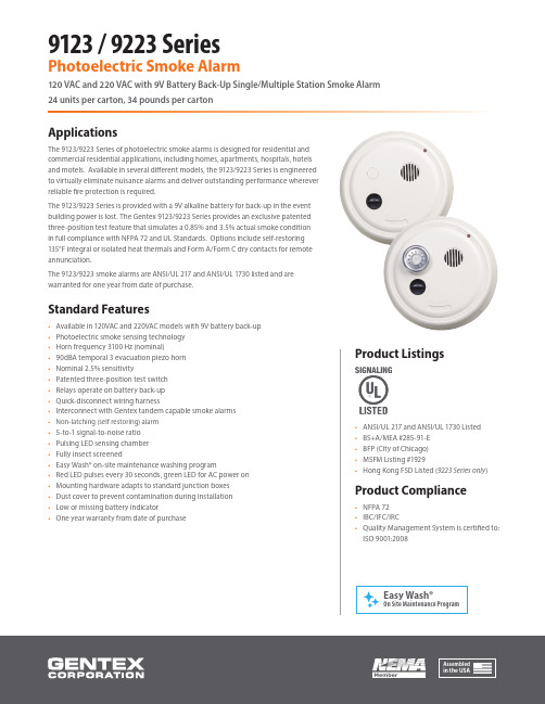
9123 / 9223 SeriesPhotoelectric Smoke Alarm120 VAC and 220 VAC with 9V Battery Back-Up Single/Multiple Station Smoke Alarm 24 units per carton, 34 pounds per cartonApplicationsThe 9123/9223 Series of photoelectric smoke alarms is designed for residential andcommercial residential applications, including homes, apartments, hospitals, hotelsand motels. Available in several different models, the 9123/9223 Series is engineeredto virtually eliminate nuisance alarms and deliver outstanding performance whereverreliable fire protection is required.The 9123/9223 Series is provided with a 9V alkaline battery for back-up in the eventbuilding power is lost. The Gentex 9123/9223 Series provides an exclusive patentedthree-position test feature that simulates a 0.85% and 3.5% actual smoke conditionin full compliance with NFPA 72 and UL Standards. Options include self-restoring135°F integral or isolated heat thermals and Form A/Form C dry contacts for remoteannunciation.The 9123/9223 smoke alarms are ANSI/UL 217 and ANSI/UL 1730 listed and arewarranted for one year from date of purchase.Standard Features• Available in 120VAC and 220VAC models with 9V battery back-up• Photoelectric smoke sensing technology• Horn frequency 3100 Hz (nominal)• 90dBA temporal 3 evacuation piezo horn• Nominal 2.5% sensitivity• Patented three-position test switch• Relays operate on battery back-up• Quick-disconnect wiring harness• Interconnect with Gentex tandem capable smoke alarms• Non-latching (self restoring) alarm• 5-to-1 signal-to-noise ratio• Pulsing LED sensing chamber• Fully insect screened• Easy Wash® on-site maintenance washing program• Red LED pulses every 30 seconds, green LED for AC power on• Mounting hardware adapts to standard junction boxes• Dust cover to prevent contamination during installation•Low or missing battery indicator• One year warranty from date of purchaseProduct Listings• ANSI/UL 217 and ANSI/UL 1730 Listed• BS+A/MEA #285-91-E• BFP (City of Chicago)• MSFM Listing #1929• Hong Kong FSD Listed (9223 Series only)Product Compliance• NFPA 72• IBC/IFC/IRC• Quality Management System is certified to:ISO 9001:20089123 / 9223 SeriesModel Part Number Voltage (VAC)Integral135ºF ThermalIsolated135ºF ThermalTandemUp To 12 UnitsTandemUp To 6 UnitsForm A/CContacts9123917-0012-002120 VAC•9123T917-0013-002120 VAC••9123H917-0014-002120 VAC••9123F917-0015-002120 VAC••9123TF917-0017-002120 VAC•••9123HF917-0016-002120 VAC•••9223917-0032-002220 VAC•9223T917-0033-002220 VAC••9223H917-0034-002220 VAC••9223F917-0035-002220 VAC••9223TF917-0037-002220 VAC •••9223HF917-0036-002220 VAC•••Notes• Series available in round configuration only• When testing 9123 Series, it may take up to 16 seconds longer for smoke alarm to go in or out of alarm mode• It is recommended that 9123/9223 Series smoke alarmbe tested weekly• Refer to Technical Bulletin 002 for Easy Wash® on site washing instructions• Units produce a temporal 3 audible alarm Electrical SpecificationsOperating Voltage (9123) ................................................120 VAC, 60 Hz Operating Voltage (9223) ................................................220 VAC, 50 Hz Operating Current .............................................................0.045 amps Operating Current (Relay Options) ..............................0.070 amps Operating Ambient Temp Range .................................40°F to 100°F Alarm Horn Rating .............................................................90dBA at 10 feet Nominal Sensitivity ...........................................................2.5% obscuration “F” Auxiliary Relay ..............................................................1 Form A and1 Form C (0.6 amp)“T” Integral Thermal (Self-Restoring) ..........................135°F at 50 feet “H” Isolated Thermal Form A (Self-Restoring) .........135°F at 50 feet Size ..........................................................................................Diameter: 6.5” OA(5.75” at base)Depth: 2.625”Secondary Power Source ................................................Alkaline 9V battery Duracell® MN 16049123 / 9223 Series - Photoelectric Smoke AlarmTandem Wiring DiagramRelay ModelsModels: 9123F, 9123TF, 9223F, 9223TF Isolated Thermal withOptional Accessory ContactsModels: 9123H, 9123HF, 9223H, 9223HFLimitations• Maximum of 12 alarms (9123, 9123T, 9123H, 9223, 9223T, 9223H) may be connected together• Do not exceed 125 ft. between each alarm• Do not exceed 1125 ft. between the first and last alarm • Note: Gentex smoke alarms can not be interconnected to alarms from other manufacturers• A maximum of six (6) alarms with a relay may be tandem interconnected (9123F, 9123TF, 9123HF, 9223F, 9223TF, 9223HF)Caution• RED/YELLOW wire to be capped when not in use • This wire is for tandem connection only • Do not connect to any other circuitRelay Contacts Rated Load Resistive• 1.0 AMP @ 24 VDC• 0.6 AMP @ 125 VAC MAX • 0.3 AMP @ 220 VAC MAXBRN Smoke Alarm Heat SensorAccess ContactsAlarm Contacts Tandem PowerH F O n l yBRN GRAY GRAY YEL ORN BLU VIO VIO/BLK RED/YEL BLKWHTGRAY Supervision WiresAccess ContactsAlarm ContactsTandem PowerGRAY YELORN BLUVIO VIO/BLK RED/YEL BLK WHTQuickDisconnect Type Plug123123123120 Volts 60 HzElectrical BoxElectrical BoxNeutralWHT TandemRED /YEL To additionalGentex smoke alarmsHot BLKElectrical BoxSmoke AlarmSmoke AlarmSmoke AlarmThe photoelectric smoke alarm shall be a Gentex model 9123/ 9223 or approved equal which shall provide at least the following features and functions.• Nominal sensitivity shall be 2.5%• The alarm shall utilize an infrared LED sensing circuit which pulses in 4 to 5 second intervals when subjected to smoke. After 2 consecutive pulses in smoke, the alarm will activate.• The alarm shall have a 9V alkaline battery as a back-up in the event building power is lost.• The 9V battery impedance shall be verified by the circuitof the smoke alarm.• The alarm shall provide an indicator when the batteryis low in power, or high impedance, or is missing.• The alarm shall provide minimum 5-to-1 signal-to-noise ratio in the optics frame to assure stability of operation in environments of high RF and transient conditions.• The sensing chamber shall be fully screened to prevent entrance of small insects, thus reducing the probabilityof false alarms.• A temporal 3 piezo alarm rated at 90dBA at 10ft.• A visual LED monitor (condition indicator) will slowpulse in normal operation and rapid pulse in alarm.• An easily accessible test knob shall be provided. The test knob in the TEST position will simulate an actual smoke condition of approximately 3.5% causing the detector to alarm within 20-36 seconds. It will also have the capability of testing to 0.85% as arequired minimum. A magnetic switch closure or other switch closure, or smoke generating equipment which does not scatter the light beam or test sensitivity is not sufficient,as indicated in National Code.• The detector shall have interconnect capabilities of up to 12 units or 6 units with relay.• The alarm shall have interconnection capabilities of12 units on 9123/9123T/9123H/9223/9223T/9223H andshall have interconnection capabilities of 6 units on9123F/9123TF/9123HF/9223F/9223TF/9223HF.• The manufacturer shall provide other compatible alarm models with the following optional features: a) 135°F isolated thermal with normally opened contact for remote connection to local alarm or annunciator; b) 135°F integral thermal; c) auxiliary Form A/Form C relay contacts for initiating remote functions and annunciation; d) relay option that is capable of activation by tandem interconnect wire. Thermal sensor shall be self-restoring.• Unit must be ANSI/UL 217 and ANSI/UL 1730 listed for both wall and ceiling mount.• Unit shall be listed by Underwriters Laboratories.All equipment shall be completely factory assembled, wired and tested, and the contractor shall be prepared to submit a certified letter testifying to this condition. Alarms which do not meet all of the requirements of this specification will not be considered.9123 / 9223 Series Photoelectric Smoke Alarm Architect & Engineering Specifications。
铱迅第二代防火墙系统管理员手册说明书

铱迅第二代防火墙系统管理员手册南京铱迅信息技术股份有限公司Nanjing YXLink Information Technology Co.Ltd.注意:●未经南京铱迅信息技术股份有限公司(Nanjing YXLink Information Technology Co.,Ltd.,简称:铱迅信息)的事先书面许可,对本产品附属的相关手册之所有内容,不得以任何方式进行翻版、传播、转录或存储在可检索系统内,或者翻译成其他语言。
●本手册没有任何形式的担保、立场表达或其他暗示。
若有任何因本手册或其所提到之产品信息,所引起直接或间接的数据流失、利益损失或事业终止,铱迅信息不承担任何责任。
●铱迅信息保留可随时更改手册内所记载之硬件及软件规格的权利,而无须事先通知。
●本手册描述的“铱迅第二代防火墙系统”之功能,并非所有型号都支持,对于每个型号拥有的功能模块,请咨询供货商或联系铱迅客服人员。
●本公司已竭尽全力来确保手册内信息的准确性和完善性。
如果您发现任何错误或遗漏,请向铱迅信息反映。
对此,我们深表感谢。
商标信息铱迅信息、铱迅信息的标志、铱迅第二代防火墙系统标志为南京铱迅信息技术股份有限公司的商标或注册商标。
本手册或随铱迅信息产品所附的其他文件中所提及的所有其他商标名称,分别为其相关所有者所持有的商标或注册商标。
版本历史版本发布时间说明1.32019年12月24号更换产品logo和截图阅读指导如果您是第一次使用铱迅第二代防火墙系统,建议您首先阅读如下章节:3.安装部署4.安装及初始化5.快速使用指南6.开始使用如果您做日常入侵告警的查看和分析,建议阅读如下章节:7.系统监控8.数据中心如果您是高级用户,建议重点阅读如下章节:9.策略配置10.网络配置11.VPN配置12.系统管理13.用户管理14.Console功能15.复位与还原如果您想了解产品特点及规格,建议阅读如下章节:1.简介2.产品规格如果您有问题需要寻求答案,建议阅读如下章节:16.常见问题与解答目录前言: (16)1.简介 (18)1.1产品介绍 (18)1.2技术特点 (18)2.产品规格 (19)2.1面板说明 (19)2.1.1接口说明 (20)3.安装部署 (21)3.1透明网桥模式 (21)3.1.1单一混合型Web服务部署模式 (21)3.1.2单一分离式应用服务部署模式 (23)3.1.3集群式/集中式应用服务部署模式 (24)3.1.4半分散式应用服务部署模式 (25)3.1.5全分散式应用服务部署模 (27)3.1.6部署环境举例 (28)3.2网关模式 (29)3.2.1部署环境举例 (29)4.安装及初始化 (31)4.1打开安装箱 (31)4.2安装设备 (31)4.3选择部署方案 (31)4.4初始化设备 (32)4.4.1连接设备的Console口 (32)4.4.2连接设备的DSI接口 (33)4.4.3配置DMI接口网络参数 (35)5.快速使用指南 (38)5.1修改密码 (38)5.2.1系统监控 (39)5.2.2版本信息 (40)5.2.3授权信息 (41)5.2.4查看入侵记录 (42)5.2.5查看网络流量 (42)5.2.6关机和重启 (43)6.开始使用 (44)6.1登录 (44)6.1.1登录系统 (44)6.1.2系统管理员登录 (45)6.1.3安全审计员登录 (46)6.1.4安全管理员登录 (47)6.2密码修改 (50)6.3欢迎页面 (50)6.4功能菜单 (51)6.4.1数据中心 (51)6.4.2策略配置 (52)6.4.3网络配置 (53)6.4.4VPN配置 (54)6.4.5系统配置 (55)6.5通用菜单、按钮介绍 (56)6.5.1保存和应用功能 (56)6.5.2重置和取消功能 (56)6.5.3刷新功能 (57)6.5.4多选功能 (57)6.5.5双击功能 (57)6.5.6翻页功能 (58)6.5.7排序功能 (59)6.5.8选择列功能 (59)7.系统监控 (60)7.1快捷方式 (60)7.2风险等级 (60)7.3系统状态 (61)7.4外部威胁来源分布图 (62)7.5威胁IP Top10视图 (62)7.6威胁Top10视图 (63)7.7威胁分类统计图 (64)7.8接口流量 (64)7.9网络接口 (65)7.10系统运行日志 (65)7.11设备信息 (66)7.12布局换肤 (67)7.13流量统计-应用分类 (67)7.14流量统计-应用 (67)7.15流量统计-IP (68)7.16实时流量-应用分类 (69)7.17实时流量-应用 (69)7.18实时流量-IP (70)7.19新建连接数 (70)7.20并发连接数 (71)8.数据中心 (71)8.1入侵事件 (71)8.1.1入侵记录 (71)8.1.2入侵查询 (76)8.1.3入侵统计 (77)8.1.4防病毒记录 (78)8.1.5DDOS记录 (80)8.1.6ARP防护日志 (80)8.1.7关键字过滤日志 (80)8.2监视 (81)8.2.1IP地址流量统计 (81)8.2.2应用流量统计 (83)8.2.3接口历史流量 (85)8.2.4IP地址实时流量 (85)8.2.5应用实时流量 (86)8.2.6接口实时流量 (87)8.3报表 (87)8.3.1报表管理 (88)8.3.2即时报表 (88)8.3.3定期报表 (89)8.4日志 (89)8.4.1系统日志 (89)8.4.2PPPoE日志 (90)9.策略配置 (91)9.1策略配置 (91)9.1.1访问控制 (91)9.1.2访问控制基本环境举例: (94)9.1.3NAT配置 (100)9.1.4端口映射 (103)9.1.5MAC地址绑定 (104)9.1.6DDOS防护 (107)9.1.7链路负载均衡 (109)9.1.8服务器负载均衡 (112)9.1.9ARP攻击防护 (115)9.1.10长连接组 (116)9.2规则配置 (117)9.2.1防护策略配置 (117)9.2.2防病毒策略配置 (119)9.2.3自定义规则 (120)9.2.4内置规则 (122)9.2.5内置防病毒规则 (124)9.2.6内置应用列表 (125)9.2.7禁用列表 (125)9.2.8关键字过滤 (126)9.2.9文件类型过滤 (127)9.3对象配置 (128)9.3.1IP地址 (128)9.3.2IP地址组 (129)9.3.3MAC地址 (131)9.3.4服务 (134)9.3.5计划任务 (136)9.3.6蜘蛛设置 (139)9.3.7运营商地址 (141)9.3.8内网地址配置 (141)10.网络配置 (142)10.1接口 (142)10.1.1网络接口 (142)10.1.2虚拟网桥 (148)10.1.3PPPoE设置 (149)10.1.4VLAN网络设置 (149)10.1.5接口管理 (150)10.1.6端口汇聚算法 (151)10.2路由 (151)10.2.1静态路由 (151)10.2.2路由信息 (152)10.3高级网络应用 (152)10.3.1本地DNS配置 (152)10.3.2DNS代理 (153)10.3.3动态DNS (155)10.3.4UPnP服务 (156)10.3.5HTTP缓存加速 (157)10.3.6DHCP服务 (159)10.3.7镜像流量监测 (160)10.3.8BYPASS (160)10.4OSPF路由 (161)10.4.1OSPF接口 (161)10.4.2使能网段 (163)10.4.3全局配置 (164)10.4.4OSPF信息 (165)10.5RIP路由 (167)10.5.1RIP接口 (167)10.5.2使能网段 (168)10.5.3邻居配置 (169)10.5.4全局配置 (169)10.5.5RIP信息 (171)11.VPN配置 (172)11.1IPSec VPN (172)11.1.1连接管理 (172)11.1.2证书管理 (175)11.1.3全局配置 (176)11.1.4连接日志 (177)11.1.5环境示例 (178)11.2PPTP VPN (184)11.2.1服务器配置 (184)11.2.2用户管理 (185)11.2.3会话管理 (186)12.系统配置 (186)12.1基本配置 (186)12.1.1时间设置 (186)12.1.2产品授权 (186)12.1.3配置管理 (187)12.1.4告警管理 (188)12.1.5磁盘清理 (190)12.1.6升级配置 (191)12.1.7版本管理 (192)12.1.8杂项配置 (192)12.2高级配置 (192)12.2.1SNMP Trap (192)12.2.2SNMP (193)12.2.3SYSlog (193)12.2.4抓包工具 (194)12.2.5网络工具 (195)12.2.6重新启动 (197)12.2.7高可用性 (198)12.2.8配置同步 (199)13.用户管理 (201)14.Console功能 (205)14.1主菜单 (205)14.2配置菜单(configure) (206)15.复位与还原 (208)16.常见问题与解答 (208)附录A.出厂默认设置 (211)设备设置接口(DSI接口)初始设置 (211)预置账号 (211)安全审计员预置账号 (211)安全管理员预置账号 (211)Console用户预置帐号 (211)默认设置 (212)前言:文档范围本文将覆盖铱迅第二代防火墙系统的硬件产品规格和Web管理界面的所有功能特点,并详细介绍该系统的具体使用方法。
TESZ1110 S 双重隔离双层高压电源说明书
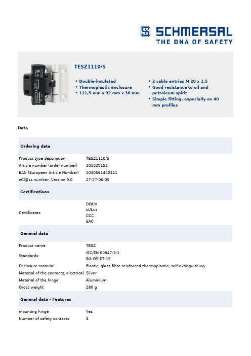
DataOrdering dataProduct type descriptionTESZ1110/S Article number (order number)101029152EAN (European Article Number)4030661449111eCl@ss number, Version 9.027-27-06-09CertificationsCertificates DGUVcULusCCC EACGeneral dataProduct nameTESZ StandardsIEC/EN 60947-5-1 BG-GS-ET-15 Enclosure material Plastic, glass-fibre reinforced thermoplastic, self-extinguishing Material of the contacts, electrical SilverMaterial of the hingeAluminium Gross weight 280 gGeneral data - Featuresmounting hingeYes Number of safety contacts 3TESZ1110/SDouble-insulatedThermoplastic enclosure111,5 mm x 92 mm x 36 mm 2 cable entries M 20 x 1.5Good resistance to oil and petroleum spiritSimple fitting, especially on 40mm profilesSafety appraisalStandards ISO 13849-1Mission Time20 Year(s)Safety appraisal - Safety outputsB10d Normally-closed contact2,000,000 Operations(NC)B10d Normally open contact (NO)1,000,000 OperationsMechanical dataMechanical life, minimum1,000,000 OperationsPositive break angle14 °Positive break force, minimum 1 NMechanical data - Connection techniqueTerminal Connector Screw connectionCable section, minimum0.5 mm²Cable section, maximum 1 mm²Note (Cable section)All indications about the cable section are including the conductor ferrules. Mechanical data - DimensionsLength x Width x Height Suitable for mounting to profile systems: 40 mmHeight of sensor92 mmLength of sensor36 mmWidth of sensor111.5 mmAmbient conditionsProtection class IP65Ambient temperature, minimum-25 °CAmbient temperature, maximum+65 °CAmbient conditions - Insulation valueRated impulse withstand voltage 2.5 kVElectrical dataThermal test current 2.5 AUtilisation category AC-15230 VACUtilisation category AC-15 2 AUtilisation category DC-1324 VDCUtilisation category DC-13 1 ASwitching element Opener (NC) Switching principle Creep circuit element Switching frequency120 /hNotesNote (General)The opening angle has been set to 4° in factory.The additional hinge including mounting accessories is also available separately, part number TES/SOrdering codeProduct type description:TESZ(1)(2)(3)(4)/(5)(6)/(7)(1)without Material of the hinge AluminiumX Material of the hinge Stainless steel(2)R mechanische Wiederanlaufsperre(3)10 1 NC contact102 1 NC contacts / 1 NO contact110 2 NC contact1102 2 NC contacts / 1 NO contacts1110 3 NC contact(4)without Screw connectionST1Connector bottom (M12, 8 pole)ST2Connector top (M12, 8 pole)(5)without with additional hingeS without additional hinge(6)30Suitable for mounting to profile systems 30 mm 35Suitable for mounting to profile systems 35 mmwithout Suitable for mounting to profile systems 40 mm45Suitable for mounting to profile systems 45 mm(7)without Switching angle NC contact at 4 degrees5°Switching angle NC contact at 5 degrees8°Switching angle NC contact at 8 degreesPicturesProduct picture (catalogue individual photo)ID: ktez-f06| 598,2 kB | .jpg | 352.778 x 314.678 mm - 1000 x 892Pixel - 72 dpi| 47,3 kB | .png | 74.083 x 65.969 mm - 210 x 187Pixel - 72 dpi| 70,6 kB | .jpg | 27.093 x 24.13 mm - 320 x 285 Pixel -300 dpiDimensional drawing basic componentID: 5tez-g03| 6,1 kB | .png | 74.083 x 61.031 mm - 210 x 173 Pixel- 72 dpi| 194,2 kB | .jpg | 352.778 x 291.042 mm - 1000 x 825Pixel - 72 dpi| 43,9 kB | .cdr || 43,4 kB | .jpg | 112.889 x 93.133 mm - 320 x 264Pixel - 72 dpiSwitch travel diagramID: ktes-s05| 16,8 kB | .jpg | 112.889 x 38.453 mm - 320 x 109Pixel - 72 dpi| 19,3 kB | .cdr || 1,7 kB | .png | 74.083 x 25.047 mm - 210 x 71 Pixel -72 dpiDiagramID: ktes-k05| 23,7 kB | .jpg | 112.889 x 48.683 mm - 320 x 138Pixel - 72 dpi| 18,4 kB | .cdr |K.A. Schmersal GmbH & Co. KG, Möddinghofe 3, D-42279 WuppertalThe details and data referred to have been carefully checked. Images may diverge from original. Further technical data can be found in the manual. Technical amendments and errors possible.Generated on 08.07.2020 17:25:59。
SOP EHS-000-01废弃物处理控制制度
公司名称公司名称英文翻译编号:SOP EHS-001-04标准管理程序页码:1 of 5名称:废弃物处理控制制度生效日期:起草人/日期:批准人/日期:审核人/日期:1 目的PURPOSE为了实现本公司环境方针目标,对公司生产、生活过程中产生的废弃物进行妥善处理、有效控制,以减少对环境的污染。
2 范围SCOPE适用于本公司生产、生活过程中产生的固态和液态废弃物的收集、标识、贮存、处置。
3 定义DEFINITION3.1 危险废弃物:是指列入国家危险废物名录或者根据国家规定的危险废物鉴别标准和鉴别方法认定的具有危险特性的废物。
3.1.1 特性:腐蚀性、毒性、易燃性、反应性、感染性。
3.1.2 危害:随意处置危险废弃物会造成地下水体和土壤等环境严重污染。
对人体健康造成中毒、致癌、致畸、致变等损害。
3.2 一般工业固体废物:是指从工业生产、交通运输、邮电通信等行业的生产生活中产生的没有危险性的固体废物。
3.2.1 一类:按照《固体废物浸出毒性浸出方法》(GB5086-1997)规定方法进行浸出试验而获得的浸出液中,任何一种污染物的浓度均未超过《污水综合排放标准》(GB8978-1996)中最高允许排放浓度,且pH值在6~9之间的一般工业固体废物。
3.2.2 二类:按照《固体废物浸出毒性浸出方法》(GB5086-1997)规定方法进行浸出试验而获得的浸出液中,有一种或一种以上的污染物浓度超过《污水综合排放标准》(GB8978-1996)中最高允许排放浓度,或者pH值在6~9的之外的一般工业固体废物。
4 职责RESPONSIBILITIES4.1 废弃物产生部门:①危废及时转移到危险废弃物仓库,相关人员负责粘贴危险废弃物标签,按要求放置,不可混放、乱放,并按要求填写《危险废弃物管理台账》。
①《危险废弃物管理台账》记录表编号由EHS部填写并放在现场,如现场记录表用完,至EHS部门领取编号打印记录表,(编号顺序格式为:年度—001~999,例2022-001)①负责危废存放点的卫生和整洁。
巡检报告模板--EMC

检查是否每个SP的write cache已处于enable状态
√正常异常N/A
检查是否每块HBA连接到存储的路径都能正常login和register
√正常异常N/A
通过“navicli -h SP_IP_Address getagent”检测SP agent的工作状态是否正常
√正常异常N/A
CX500
基本配置信息
设备型号
cx 500
设备序列号
CK2000443XXXXX
SP Flare code版本
0.2.07.500.5.XXX
SPS数量
2
硬盘(PN:容量*数量)
15*146G
扩展柜(型号或无)
N/A
硬件状态检查
检查内容
检查结果
备注
通过CAP2检查磁盘有无ቤተ መጻሕፍቲ ባይዱ障(Hard error)
√正常异常N/A
通过CAP的issues和analysis检查有无其他报错(例如health-check failed,磁盘的soft error等)
√正常异常N/A
检查两个SP状态
√正常异常N/A
检查磁盘柜每个LCC状态
√正常异常N/A
检查SPE的每个风扇状态
√正常异常N/A
检查磁盘柜每个电源状态
根据主机类型检查所有HBA卡的failover设定是否正确 (通过connectivity status…)
√符合不符合N/A
检查内存是否已被完全分配给Cache用
√符合不符合N/A
检查Write cache的High,low watermark是否已被设置正确
√符合不符合N/A
巡检总结
设备总体运行正常
- 1、下载文档前请自行甄别文档内容的完整性,平台不提供额外的编辑、内容补充、找答案等附加服务。
- 2、"仅部分预览"的文档,不可在线预览部分如存在完整性等问题,可反馈申请退款(可完整预览的文档不适用该条件!)。
- 3、如文档侵犯您的权益,请联系客服反馈,我们会尽快为您处理(人工客服工作时间:9:00-18:30)。
封面发行目录1.0 目的:为了达到事故预防的目的,对公司内可能发生的紧急情况在事前做出应急预案,做好事前的准备,以便于在紧急情况发生时,采取相应的措施,将事故造成的损失降低到最小。
2.0 适用范围:本程序适用于定义中描述的各种紧急情况,同时包括对应急各环节的管理,包括事前的准备和紧急情况发生的响应。
事前的准备包括设备和物品的准备(配备、检查、维护修理和更新)、人员的准备(组织、分工、培训和演练)和预案程序的准备(编写、传达、培训、演练和更新)。
响应行为包括事故控制、报警、撤离、抢救、现场后处理、调查、通报、善后和纠正措施等环节。
3.0 职责:3.1 厂长负责确认本程序在公司的制订和实施运行。
3.2 EHS部负责公司应急响应程序的制订,并组织各具体应急计划书的制订和组织实施。
3.3 各部门根据应急计划中规定的相应职责对设备、人员和程序进行管理。
3.4 全体在公司现场的人员(包括外来人员)必须服从公司的应急指挥。
3.5 技术经理为工厂内单体安全管理代表。
4.0 定义:紧急情况在JINHAAS指以下情况:4.1火灾和爆炸4.2溢出、泄漏、蒸气释放4.3恶劣气候(大风、暴雨、大雪)4.4民事或刑事干扰4.5恐怖主义及炸弹威胁4.6严重人身伤害或死亡4.7厂区外影响到工厂的紧急情况4.8厂区内影响到周围社区的紧急情况4.9运输紧急情况4.10公用设施故障4.11紧急医疗响应5.0 具体要求:5.1 通用要求:各类紧急情况的应急准备和响应有一些共性的要求,在本节中描述,以对各类事故准备和响应进行指导。
内容分为两部分:事前的准备和发生时的响应。
5.2 事前的准备:5.2.1 设备和物资的准备5.2.1.1 配备:根据应急响应的需要,事前必须配备必要的应急设备和物品如应急广播系统、泡沫消防系统、充足的灭火器、吸附用的吸油棉和沙子、单体消除液、防护用的PPE、应急照具、各类标识(包括逃离指示)、AN的急救药物等。
5.2.1.2 检查:对配备的应急设备和物品必须定期进行检查(不能少于半年一次,具体频率见各分类计划的规定),以保证其处于正常可使用状态。
5.2.1.3 维护和修理:对设备要周期性检查(具体规定见各分类计划),对存在问题的设备要及时快速地修理,修理前应做好替代的方案。
5.2.1.4 更新:对于失灵、老旧的设备应考虑及时更换新的设备,对于有使用期限的物品,如单体消除液、应急药品等,要及时更换。
5.2.2 人员的准备5.2.2.1 组织:在公司内建立应对不同紧急情况的组织,如应急指挥中心、火灾小组、应急救护小组、泄漏小组等,以便紧急情况发生时,有相对专业的人员采取快速的反应,减少事故造成的损失和影响。
5.2.2.2 分工:对小组内的人员应有明确的分工,以保证能对自己担负的职责熟悉,以自己担负的任务熟练作业。
在熟悉本人担负职责的前提下,鼓励小组人员学习其他人的职责和作业,鼓励定期轮换,以便于更多的人掌握更多的应急知识和技巧,以提高应急队伍的响应能力。
5.2.2.3 培训:对于不同的员工进行不同的事前培训非常关键,除对各应急小组人员进行有针对性的培训外,对全体员工和外来人员,均应进行一般的应急培训和演练。
对于长期承包商,应纳入应急小组,或对其进行专门的应急培训。
注意对新员工进行应急响应的培训。
5.2.2.4 演练:事前的演练可以让人员在事前就熟悉应急响应的设备、人员组织和程序的情况,以免在紧急情况发生时产生慌乱和误操作。
同时也是对应急计划的一次检验,以便修改其中与实际不符的地方,使应急计划更具有实战的指导性。
演练应定期进行。
应包括更多的人员参加,以增加感性认识。
5.2.3 预案程序的准备5.2.3.1 编写:对定义中规定的各类紧急情况均应提前编写出书面的应急预案,以作为应急响应时的指导和不断完善的基础。
编写时应予参照国家法规、公司安全标准和工厂的实际情况。
5.2.3.2 传达:公司的应急预案应及时传达到相关的人员,文本和电子文件应分发到各部门,必要时,可以将有关应急准备和响应的内容制作成展板形式进行公示。
5.2.3.3 培训:对于应急预案中的内容必须进行及时有效的培训,以保证相关人员理解和执行。
5.2.3.4 演练:对应急响应的部分,应定期组织演练,以保证响应的快速和准确性。
同时,对与实际不符的地方应及时进行修改。
5.2.3.5 更新:应急预案应根据演练的结果进行修改;在设备、物品和组织机构变更时,应及时更新内容;同时,每三年应进行一次例行的评审,以保证预案的内容和要求与实际相吻合。
5.3 响应行为:5.3.1 事故控制:在任何事故发生时,初步的控制都可以有效地防止事态的扩大。
在不会影响作业者本人生命安全的前提下,要求事发现场的人员必须对事故采取控制措施,如使用灭火装置灭火、使用吸附物品吸附和围堵泄漏等措施。
同时,对事故现场进行人员管制,限制无关人员的进入。
5.3.2 报警:在对事故进行初步处理和控制后,要及时向应急指挥中心报警,在安全的情况下尽快通知相关的人员。
应急指挥中心应对根据事态的判断,立即通告相关的区域和人员。
同时指挥各部门人员执行应急计划。
如果事态影响到周围的社区,应及时通知社区的企业和居民,以采取相应的应急措施或撤离。
需要消防部门或医务部门支援时,立即拨打119或者120(也可以根据伤势程度先联系)5.3.3 撤离:在事故难于控制,需要人员(或部分人员)撤离时,公司内人员(包括外来人员)应先撤离到紧急撤离集合区,在清点人员后,有组织地撤离。
工厂北门附近警卫室内作为公司的厂外指挥中心,配备必要的应急用品。
5.3.4 抢救:对于在事故中受伤的人员,公司员工应根据伤害的情况进行现场初步救护处理(如冲洗、包扎和固定等)(紧急救护小组的人员应发挥更大的作用),向本部门负责人和EHS部汇报,然后立即拨打120或草庙子医院5584031,金泓医务室5583620 ,404医院5344120(电话应在公司内多个地点张贴),呼叫专业医务人员人员进行救护。
5.3.5 现场后处理:在事态稳定后,对事故现场应及时进行后处理,以避免连锁事故的发生,和减少对环境和人员健康的影响。
5.3.6 调查:及时展开对事故原因的调查,有助于对事故根本的原因进行消除。
调查应让更多的员工参与进来,以保证客观公正。
对于责任事故,要明确各级员工的责任。
5.3.7 通报:在事故发生后短时间内应按公司关于事故级别的要求,通报亚太区和总公司的相关人员。
在事故报告写出来后,要及时上报给亚太区安全经理及相关人员,必要时通报社区或相关方(客户、媒体等)。
伤亡事故发生时,要及时通知家属。
环境污染事件须通报给环保局。
如果法律有其他的通报要求,应遵照法律的要求来进行通报。
5.3.8 善后:对于事故成的破坏,要及时修复。
对于给人员、社区形象和相关方造成的伤害和损失,应采取积极的态度处理善后事宜,避免给公司企业形象造成巨大损失。
对责任事故涉及的员工,做出相应的处罚。
5.3.9 纠正措施:根据事故调查的结果,制订整改方案,以达到防止再发生的目的。
5.4 应急预案:根据以上描述的紧急情况的准备和应急响应要求,由EHS部组织不同的部门,研讨可能发生的紧急情况,分工编写具体的应急预案,做为本程序的三级文件,文件由不同的部门管理并更新。
公司内可能发生的紧急情况见下表(具体情况应根据公司内的变化而及时更新),应急预案的格式参见附表15.5 检查与审核:5.5.1 EHS部和各部门必须按照各应急预案的要求,对各项准备工作进行检查,对发现的问题应及时通报并采取整改措施。
5.5.2 EHS部在年度审核时,应对公司的整体应急响应体系进行审核。
5.6 产生的记录:5.6.1 各类紧急情况的应急预案。
5.6.2 各类应急组织的名单5.6.3 种类应急设备和物品的检查计划和检查记录5.6.4 各类应急预案的培训和演练记录5.6.5 事故发生时调查和处理记录5.7 相关的标准和文件:5.7.1Emergency Response Plans (EHS507标准)5.7.2Safety Equipment Inspection(EHS522标准)5.7.3Protective Devices, Emergency Alarms and Interlocks(EHS523标准)5.7.4Safety Drench Showers and Eye-Face Wash Stations(EHS530标准)5.7.5Fire Prevention and Protection(EHS524标准)5.7.6EHS培训管理程序(EHS–OP–05)5.7.7检查与测量管理程序(EHS-OP-11)附表1:应急预案(格式)(内容供参考)应急预案名称:原料储罐的起火爆炸(应急预案)(包含地点区域和紧急情况的描述)本预案负责人:编写部门:编写人:原料储罐的火灾和爆炸应急响应小组结构图联系亚太区危机处理小组如为等级3事故,在几小时内须联系亚太区危机处理小组联系亚太区危机处理小组,事故发生地的国家经理联系亚太区危机处理小组的其他成员并解释紧急状况。
国家经理和亚太区危机处理小组成员确定电话会议的时间及如何分工。
亚太区危机处理小组的电话会议电话为65-879-4944,主席PIN为*9999*(包括二个星号)。
仅主席(打电话的第一人)需拨PIN,主席能在电话会议期间得到帮助,拨*10*能得到电话公司的协助。
亚太区危机处理小组确保以适当的方式对受影响的基地、员工、社区、组织、顾客提供帮助。
*****总公司危机处理中心电话为(24小时开通)1-215-592-3000**** 总公司危机处理小组24小时值班,只要打这个电话,告诉警卫事故所属等级,警卫会联系危机处理小组成员并回电。
罗门哈斯总公司危机处理中心会派一名专家提供建议并予以支持。
在危机中小组成员会一起提供帮助。
The Corporate Crisis Team can be reached at 215-592-3000.The DOW On call Doctor Consultation: 989-636-4400。
