珠海施诺S365系列装置说明书(V3.1)
角度ков里元 com 过电安全意识系踋 18.01.21 的用户指南 (zh-TW)说明书
Bosch Sicherheitssysteme GmbH
Configuration Manual
目錄 | zh-TW 5
57 58 58 59 59 59 60 60 61 62 62 63 64 64 66 67 68 68 69 69 69 69 70 71 71 71 73 73 74 76 76 76 78 79 79 80 81 82 83 83 84 85 87 88 88 88 89 89 90
編輯編碼器 / 編輯解碼器對話方塊 管理真實性驗證 設置驗證 上傳憑證 下載憑證 在工作站上安裝憑證 提供解碼器的目的地密碼 (驗證...) 變更編碼器 / 解碼器的密碼 (變更密碼 / 輸入密碼) 從更換的編碼器復原錄影 (與前身的錄影建立關聯) 設置編碼器 / 解碼器 設置多個編碼器 / 解碼器 錄影管理頁面 錄影偏好設定頁面 設置多點傳播 地圖與結構頁面 連續畫面產生器對話方塊 新增連續畫面對話方塊 新增連續畫面步驟對話方塊 設置「邏輯樹狀結構」 設置「邏輯樹狀結構」 新增服務至「邏輯樹狀結構」 移除樹狀結構項目 管理預先設置的攝影機連續畫面 新增攝影機連續畫面 新增資料夾 設置略過裝置 攝影機與錄影 頁面 攝影機 頁面 PTZ/ROI 設定對話方塊 設置攝影機與錄影設定 設置 PTZ 連接埠設定 設置 PTZ 攝影機設定 使用者群組 頁面 使用者群組屬性 頁面 使用者屬性 頁面 登入組屬性 頁面 攝影機權限 頁面 LDAP 伺服器設定對話方塊 邏輯樹狀結構 頁面 操作員功能頁面 使用者介面 頁面 帳戶原則頁面 設置使用者、權限與企業存取功能 建立群組或帳戶 建立標準使用者群組 建立使用者 建立雙授權群組 在雙授權群組中新增登入組 設置系統管理群組
使用者介面的文字以粗體標示。 4 箭頭請您按一下劃有底線的文字,或按一下應用程式中的項目。
海林TH36D25C□-□自动控温分集水器技术规格及使用说明说明书
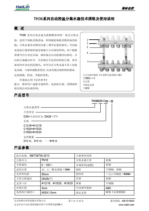
TH36系列自动控温分集水器技术规格及使用说明概 述TH36 系列分集水器为黄铜整体型材一体式分集水器,适用于地板采暖系统,控制辐射地板采暖系统的热能。
分集水器各回路均内置了调节水量的阀芯。
可加装电热执行器和温控器实现独立分室温度控制。
用户根据需要可自行设定室温,温控器会自动检测房间温度,并向执行器输出信号,关闭或打开此房间的执行器,使室温保持在设定的范围内。
也可以在分集水器主管上加装电动阀,与温控器配套使用,从而实现区域控制的要求, 达到温暖、舒适、节能的效果。
外观如右图(仅供参考)提示:推荐用户选配末端组件、电热执行器、采暖温控器实现自动恒温控制。
产品型号TH36D25 C □-□分集水器类型主管管径D25=主管管径为 DN25(1″) 芯体C1216=Φ12/16 C1520=Φ15/20 C1620=Φ16/20支管数量2=2 路;3=3 路;……8=8 路产品参数1.手动调节旋钮(可更换为电热执行器)2.TH36 主管3.芯体4.固定支架5.螺帽51 2 34产品特点拉管成型:主管与支管一体拉管成型,主体与支管无缝连接,提高了产品密封的可靠性。
自动调节:可配置电动阀与温控器实现区域控制,也可配电热执行器与温控器实现分室控制。
表面处理:树脂涂层,外观黄铜本色,耐腐蚀,造型简洁美观。
支架安装:分集水器安装带有简洁、美观、稳固的支架,便于安装,节省安装时间和空间。
安装尺寸安装提示为方便运输及用户安装,TH36 系列分集水器分解包装。
安装前,对照部件图清点配件,安装时符合《地面辐射供暖技术规程》中分集水器安装要求。
1、分集水器的安装必须由专业人员进行,安装后按标准要求进行试压,并调试合格;2、不允许使用非专业的工具切割和不做倒角处理的管材;3、地暖管安装时,管材、接头保持干净,不能使用插入端严重划伤或斜切的管材;4、地暖管安装时,应保持地暖管与分集水器主管垂直。
拧紧螺帽时,握紧地暖管,应缓慢用力,不允许用力过猛,以免因扭矩过大损坏阀体,同时防止地暖管扭曲,变形;5、管材存放和使用时,必须采取管材保护措施;6、装配堵头,阀门时,应使用生料带,不得使用麻丝之类,且生料带缠绕圈数不宜过多,以免撑坏主管;7、 安装管路应有足够的位置精度,强行连接会使管路产生过量的装配应力,使分集水器失效或损坏; 8、 应避免用不合格或公差过大的连接件与分集水器相配,以免强硬施工造成损伤;9、 管路中的杂物会增加水阻,同时破坏阀门和管件的密封性,因此在管路的进口处要求安装过滤器; 10、 为确保分集水器的安全使用,应尽量避免酸、碱等腐蚀性物质沾附其表面。
温度在线监测系统说明书V3.0
空间狭小的被测点上,与接收装置之间没有接线。光纤测温方式需要放 置光纤;红外测温方式需要调整接收装置的位置,安装都不方便。
¾ 组网灵活 系统可通过 RS485 总线,组成本地温度监测网络。还可以通过局域 网或 GPRS 移动通信网将所有数据上传监控中心,组成大范围的远方温度 监测网络。
4-3 温度传感器外形及安装方式 无线温度传感器为一体化结构,内部采用高温高能锂电池供电,内
置 LTCC 天线。外部采用高温高压热缩管封装,防水防尘,体积小巧。最 适用于空间狭小的安装位置,也可用于户外高压设备。外形见图 4-2 所 示。
图 4-2 无线温度传感器
无线温度传感器的底面是感温面,为了准确测量物体表面的温度, 应保证传感器的感温面与被测物体的表面紧密接触。安装时可用高温尼 龙扎带或采用导热硅胶粘结等方法将其固定在被测物体上。安装见图 4-3 所示。
本产品采用先进的感温电子元件与无线传输方式相结合。将温度传 感器紧贴到高压设备、母线或电缆接点、断路器触头等位置,安装快捷 方便,直接测量温度。利用 2.4G 的 zigbee 射频技术传递温度信息,实 现了传感器和被测点等电位,安全可靠。传感器由高能锂电池供电,寿 命长达 5 年。监测仪配有液晶显示器实时显示所有被测点温度,超温告 警时有常开和常闭两组信号节点输出。装置具有标准 RS485 串行通信口, 可直接与上位计算机相联组成本地温度监测网络。还可以通过局域网或 GPRS 移动通信网将所有数据上传监控中心,组成大范围的远方温度监测 网络。并提供上位机接收、存储、打印、数据分析程序软件。也可以通 过综自系统将数据上传。
珠海施诺电力科技有限公司
ZST6000光伏逆变器综合测试仪入门手册V1.02

致远电子
安全须知
本仪器的使用涉及到高压,为防止电击或其它危险造成的人员伤亡,在安装、使用或 维修本产品之前,请务必仔细阅读、并完全理解“安全须知”章节的相关内容。 为保证您能正确安全地使用本仪器, 请务必遵守以下注意事项。 如果未遵守本手册指定 的方法操作本仪器, 可能会损坏本仪器的保护功能。 因违反以下注意事项操作仪器所引起的 损伤,广州致远电子股份有限公司概不承担责任。
产品入门手册 << I
致远电子
注意搬运安全
ZST6000 入门手册
为避免仪器在搬运过程中滑落,造成仪器面板上的按键、旋钮或接口等部件损坏,请注 意搬运安全。
警示标志
注意符号表示存在危险。提示用户对某一过程、操作方法或类似情况 进行操作时,如果不能正确执行或遵守规则,则可能对产品造成损坏或者 丢失重要数据。在完全阅读和充分理解注意所要求的事项之前,请不要继 续操作。 警告符号表示存在严重危险。提示用户对某一过程、操作方法或类似 情况进行操作时,如果不能正确执行或遵守规则,则可能造成人身伤害甚 至死亡。在完全阅读和充分理解警告所要求的事项之前,请务必停止操作。
安全信息
光伏逆变器综合测试仪安全符号如下所示。
小心,危险
CE 认证
地端子
小心,电击危险
请勿将使用过的 电池丢入垃圾桶
可回收利用
CAT Ⅱ(1000V)IEC 测量Ⅱ类,输入可连接到归属到Ⅱ类过电压条件下的电源 ( 最大 1000VAC)。 一般注意事项 针对人身安全与设备保护,列出注意事项如下所述: 保护功能有缺陷。在使用仪器之前,请对保护功能进行确认。如发现 保护接地或保险丝有缺陷,请勿继续使用本仪器; 请勿拆卸仪器的机箱。仪器内部有高压,非常危险。若要对仪器内部 进行检查和调试,请咨询广州致远电子股份有限公司; 出现异味或冒烟时。出现机体冒烟或散发异味等异常情况时,请直接 关闭电源,从插座拔掉电源插头,并切断连接在输入端子的测量回路 的电源。发生异常情况时,请咨询致远公司; 勿在易燃环境下操作仪器。请勿在含有易燃易爆液体或气体的环境里 使用本仪器; 请勿损坏电源线。请勿将物品摆放在电源线上,并使电源线远离热源。 将电源插头从插座拔出时,请勿拉扯电线,而应手持插头拔出。电源 线有破损时,请在确认好零件编号后再向经销商订购;
施泰纳 IS 360-3 红外线感应器说明书
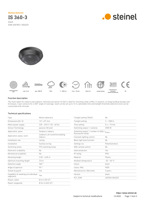
blackEAN 4007841 006525infrared sensor360°max. 12 m max. 2000 W IP54 2 - 1000 lux 5 sec - 15 min Ideal 2 m energy savingmanufacture's warrantysteinel.de/garantieCEFunction descriptionThe multi-talent for indoors and outdoors. Infrared wall sensor IS 360-3, ideal for mounting under soffits, in carports, on large building facades and driveways, 3 pyro sensors for a 360° angle of coverage, reach can be set up to 12 m, selectable time and twilight threshold, detection zone can be customised with shrouds.Technical specificationsTypeMotion detectors Dimensions (Ø x H)121 x 57 mmMains power supply 220 – 240 V / 50 – 60 Hz Sensor Technology passive infrared Application, place Outdoors, IndoorsApplication, place, room outdoors, all round the building,Indoors Installation site ceiling Installation Surface wiring Switching zones 972 switching zones Electronic scalability No Mechanical scalability NoMounting height2,50 – 6,00 m Optimum mounting height 2,8 m Detection angle 360 °Angle of aperture 90 °Sneak-by guardYesCapability of masking out individualsegments YesReach, radial Ø 6 m (28 m²)Reach, tangentialØ 24 m (452 m²)Twilight setting TEACH No Twilight setting 2 – 1000 lx Time setting5 s – 15 min Switching output 1, resistive2000 WSwitching output 1, number of LEDs /fluorescent lamps 8 pcs.Constant-lighting control No Basic light level function NoSettings via Potentiometers With remote control No Interconnection Yes IP-rating IP54MaterialPlastic Ambient temperature -20 – 50 °C Colour black Colour, RAL9005Manufacturer's Warranty 3 years Version blackPU1, EAN4007841006525blackEAN 4007841 006525Detection Zone Dimension DrawingLight without neutral conductor Light with neutral conductorConnection using two-circuit switch for manual and automatic operation Connection via a two-way switch for manual override and automatic operation。
三技术被动红外 微波防盗探测器安装手册说明书

DS825-CHI/DS825T-CHI/DS840-CHI/DS840T-CHI 安装手册 P/N :4998122944-01第1页DS825-CHI ,DS825T-CHI ,DS840-CHI ,DS840T-CHI三技术被动红外/微波防盗探测器1.0 概述DS825-CHI 和DS840-CHI 系列是以微波处理器为基础的三技术被动红外/微波防盗探测器。
它使用了先进的信号处理技术,提供了超高的探测和防误报性能,不会对一只重27公斤的狗或10猫,昆虫和飞鸟的活动而引起误报。
2.0 技术指标 • 输入电源:6—15伏直流,标准耗电电流为15毫安直流(在步测或故障状态下,耗电电流可至35毫安直流)。
• 待机电源:无内部待机电池。
与直流电源连接可提供待机电源。
每小时待机耗电为15毫安时。
在UL 认可的安装条件下,至少可待机4小时(60毫安时)。
• 报警继电器:静音操作常闭舌簧继电器。
直流抗阻负载时,接点间最大为28伏直流,3瓦特,125毫安。
并由继电器公共"C"脚上的4.7欧姆,0.5瓦特的电阻保护。
不可使用电容性或电感性负载。
• 工作温度: -40℃—+49℃。
UL 认可的安装条件下,工作温度为0℃—+49℃。
• 微波频率:DS825(T)-CHI/DS840(T)-CHI:10.525 Ghz (UL 认证) DS825TA-CHI/DS840A-CHI:10.687 Ghz DS825TB-CHI/DS840TB-CHI:9.9 Ghz • 探测范围:DS825-CHI 系列:8米×8米; DS840-CHI 系列:12米×12米 • 内部偏转:垂直+1°—8° • 可选防拆:DS825T-CHI ,DS825TA-CHI ,DS825TB-CHI ,DS840T-CHI ,DS840TA-CHI ,DS840TB-CHI 有一常闭防拆开关。
SPS-3610系列使用手册-cn

1 索引 页次1.产品介绍................................................................ 1 2产品规格................................................................ 2 2-1.一般规格............................................................. 2 2-2.定电压操作........................................................ . 3 2-3.定电流操作......................................................... 3 2-4.数位式指示表头................................................... 3 2-5.过电压保护......................................................... 3 2-6.绝缘度............................................................... 3 3.动作原理................................................................ 4 4.面板介绍................................................................ 7 4-1.前面板............................................................... 7 4-2.后面板............................................................... 7 5.操作说明................................................................10 5-1.使用前注意事项...................................................10 5-2.设定限流值.........................................................10 5-3.定电压/定电流之交越特性.......................................11 5-4.操作模式............................................................12 6一般维修................................................................13 6-1.保险丝之更换......................................................13 6-2.电源电压变换......................................................13 6-3.校正方法............................................................14 6-4.清洁方法 (15)1产品介绍本系列产品是属于仪器用的交换式直流电源供应器,改善了传统线性式电源供应器体积大、重量重、和效率差的缺点。
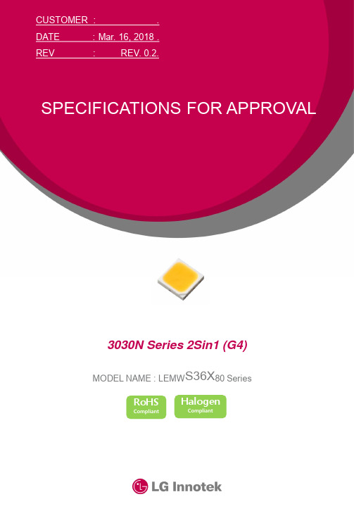
乐美S36X80系列LED灯具说明书
133 136 143
128 132 140
127 135 138
132 137 144
132 138 144
131 134 143
lm
127 130 136
127 130 136
122 126 133
Forward Voltage
VfΒιβλιοθήκη All5.80-
6.60
V
Color Coordinate
Cx / Cy
※ These values are measured by the LG Innotek optical spectrum analyzer within the following tolerances. Luminous Flux (Φv) : ±7%, Forward Voltage (Vf) : ±0.1V, Color Value : ±0.005, CRI Value : ±2,
These or any other conditions beyond those indicated under recommended operating conditions are not implied.
The exposure to the absolute maximum rated conditions may affect device reliability. ※ The LEDs are not designed to be driven in reverse bias. ※ These values are provided less than Tj 125℃
3 / 30
4. Absolute Maximum Ratings
( Ta=25℃)
PANAMETRI CS SERIE35水份仪说明书
PANAMETRICS SERIES35水份仪用户手册杭州川达仪器成套工程有限公司地址:杭州丽水路21号紫荆家园31-1-301电话:0086-571-88261597传真:0086-571-88261508 邮编:310014承诺本公司承诺每台制造的仪表在材料和制作方面无缺陷.即有缺陷的本公司免费服务,校验和将仪表返回到公司更换.这也包括电池.此承诺有有效期.须在有效期内.有效期为:●电子部分故障一年●传感器机械故障(短路或开路)一年●传感器的校验半年损坏若由误操作引起,买方应申明并为修理付费.维护方法若有任何故障,按下述进行:1.通知本公司,详述故障细节并提供仪表的型号和系列号.本公司收到后专家将根据故障情况指导你修理.2.若本公司通知你将仪表寄回,请将仪表寄回并先预付运费.3.若损坏由误操作引起或已过有效期,修理前需先预估费用.关于本手册本手册介绍了35系列仪表的安装,使用和使用.若碰到本手册未涉及的内容请与你最近的代理商联系.适合人群本手册适合安装,使用和维护仪表人员阅读.它假设读者了解一般的专业术语和分析设备.不了解本公司的人员必须使用本手册.本手册也适合于使用和维护过程控制人员.内有部分章节给安装者使用(电子,配管).手册内容手册有五章.6个附录和一个摘要.第一章:简介:简述仪表.第二章:安装:描述了怎样安装仪表的电子部分.还介绍了探头,电源,报警和模拟输出的连接.第三章:操作:解释怎样进入测量和仪表显示的数据.第四章:故障处理和维护:描述了可能发生的故障及怎样更换电池和用户程序及更换和重校验水份探头.第五章:技术规格:包含35系列电子部分和水份测量的技术规格.附录A:水份仪的应用:水份测量计算的详细技术规格.另外还包括水份探头的维护和使用技巧.附录B:外形和安装图:提供安装尺寸图.附录C:35系列菜单:提供通过用户程序可用的完整的菜单.附录D:数据信息表:提供用户记录将来所有可用信息的表格.附录E:备件目录:提供35系列备件的订货号和相应的描述..附录F:旧型号的电路板:包括旧型号电路板的结构和轮廓图.怎样使用手册本手册每一章节是独立的.后面的章节是在假设已阅读前面的章节下写出的.还有少量的信息包含在附录中.版本信息产品修正或更改时手册需升级.每页顶部有出版日期.本手册是B版.版本信息公司提供的校验数据表,包含探头所需的所有数据.另外公司还根据需要提供详细的图纸和图表.获得技术支持想获得技术支持请拨打电话:1-800-833-9438(美国或加拿大)或781-899-2719.目 录1 简介 (1)1.1 电子单元 (1)1.2 探头 (1)1.3 取样系统 (1)1.4 软件 (1)2 安装 (2)2.1 选择最佳的安装位置 (2)2.2 水份探头的注意事项 (3)2.3 取样系统指南 (4)2.4 安装取样系统 (4)2.5 将探头装入取样系统 (5)2.6 安装电子单元 (5)2.7 电子单元正确的接线 (6)3 操作 (12)3.1 启动 (12)3.2 改变测量显示 (18)3.3 设定报警继电器 (18)3.4 设置记录仪 (22)3.5 设置用户自定义的功能 (24)4 故障处理和维护 (31)4.1 常见故障 (31)4.2 屏幕显示信息 (34)4.3 更换用户程序 (35)4.4 更换和重校验水份探头 (37)4.5 试验报警继电器和模拟输出 (37)4.6 调整模拟输出的零点和终点值 (38)5 技术规格 (41)附录C (I)第一章 简 介35系列是用于测量气体中水份的,带微处理器的单通道湿度计,量程范围广,实时测量.测量范围为-110~+60℃(-166~+140℉),带一个故障继电器和一路模拟信号输出,可选配二个报警继电器。
s350_360_370_manual_v30
珠海施诺电力科技有限公司
1、产品标识及产品型号对照表
1.1、本说明书查阅方法
本说明书的内容主要是本公司产品的使用说明,随本公司产品一起提供给用户。 本说明书将几种系列的产品使用说明编撰在一起,叙述中没有特别指明型号的即为各 系列共同的部分;特别指明型号的叙述为该型号特有部分。 几种不同系列产品不同之处主要在于功能区别,需要了解各种功能的参数设置、试验 方法等内容时,首先按照产品标识的型号对照查阅“产品型号与功能对照表”,从对照表 上可以查到该型号所具备的功能。 对于一项具体的功能,如何设置参数、如何试验等使用方法可以从对应的章节查到, 按照查到的内容介绍,即可了解、掌握其使用方法。 用户也可以直接接通产品电源,按照产品人机界面显示的菜单名目,查找本说明书的 相关内容,从而达到了解、掌握产品使用方法的目的。
2、搬运、储存、开箱检查…………………………………..……..…5 3、安装……………………………………………………………….….……6 4、接线……………………………………………………………….….……7 5、端子图
5.1、S350 系列端子图…………………………..……………………8 5.2、S360 系列端子图…………………………..……………………9 5.3、S370 系列端子图……………………….......…………………10
●
●
●
●
●
●
●
●
●
●
●
●
●
●
●
●
●
●
●
●
●
●
ISA-358GE(F)备用电源自动投入装置技术使用说明书V3.21-120901
ISA-358GE(F)备用电源自动投入装置技术使用说明书Ver 3.21编写:叶志锋蔚凡杜东威审核:远生许永军批准:徐成斌长园深瑞继保自动化二〇一一年三月本说明书由长园深瑞继保自动化编写并发布,并具有对相关产品的最终解释权。
相关产品的后续升级可能会和本说明书有少许出入,说明书的升级也可能无法及时告知阁下,对此我们表示抱歉!请注意实际产品与本说明书描述的不符之处。
更多产品信息,请访问互联网:.sznari.技术支持:(0755) 3301-8668/8647/8610传真:(0755) 3301-8889/8664欢迎拨打免费客户服务:400-678-8099目录1装置概述 (1)1.1基本配置 (1)1.2主要性能特点 (2)2技术参数 (3)2.1环境参数 (3)2.2额定电气参数 (3)2.3主要技术指标 (3)2.4通讯接口 (4)2.5抗干扰性能 (4)3备自投一般性说明 (5)3.1备自投基本原则 (5)3.2备自投基本逻辑 (5)4备自投典型逻辑 (8)4.1分段备自投(FBZT) (8)4.2变压器备自投(BBZT) (9)4.3进线备自投(LBZT) (11)5保护和告警功能 (13)5.1母线TV断线告警 (13)5.2进线TV断线告警 (13)5.3全所无压告警 (13)5.4闭锁备自投告警 (14)5.5断路器拒动告警 (14)5.6分段断路器过流保护 (14)5.7分段断路器零序保护 (15)5.8进线断路器过流保护 (15)5.9进线断路器零序保护 (16)5.10过负荷联切 (17)5.11母线接地告警 (17)6辅助功能 (19)6.1信号系统 (19)6.2事故分析与过程记录 (19)7保护配置及整定说明 (25)7.1装置元件配置 (25)7.2装置定值 (26)7.3出口配置 (34)8装置动作事件类型定义 (34)9装置背板布置及端子接线 (37)9.1分段备自投元件 (37)9.2断路器保护、过负荷联切 (38)9.3变压器备自投元件 (39)9.4进线备自投元件 (39)9.5装置其它端子接线 (40)10装置订货说明 (41)10.1基本订货参数 (41)10.2装置命名规则 (41)10.3装置型号列表 (41)附录A装置使用说明 (42)A.1面板布置与显示 (42)A.2菜单界面操作说明 (43)A.3查看录波记录 (48)A.4装置通讯功能说明 (50)A.5装置打印功能 (53)附录B装置调试与投运说明 (56)B.1调试资料准备 (56)B.2通电前检查 (56)B.3上电检查 (56)B.4整机调试 (56)B.5装置投入运行操作步骤 (57)B.6装置运行说明 (58)B.7注意事项 (58)【附图1】ISA-358GE分段和进线备自投原理接线图 (60)【附图2】ISA-358GF分段和变压器备自投原理接线图 (61)【附图3】ISA-358GE/F测控原理接线图 (62)【附图4】ISA-358GE/F装置端子排接线图 (63)【附图5】ISA-358GE/F装置前视后视图 (64)【附图6】ISA-358G装置操作板(WB741B)原理接线图 (65)1装置概述ISA-358G备用电源自动投入装置,用于实现110kV及以下电压等级、不同接线方式变电站的备用电源自动投入功能。
CSD-361装置调试指导说明
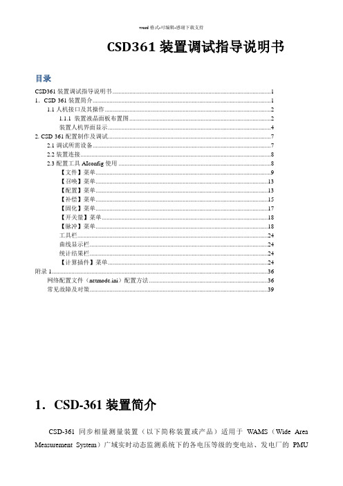
CSD361装置调试指导说明书目录CSD361装置调试指导说明书 (1)1.CSD-361装置简介 (1)1.1人机接口及其操作 (2)1.1.1 装置液晶面板布置图 (2)装置人机界面显示 (4)2. CSD-361配置制作及调试 (7)2.1调试所需设备 (7)2.2装置连接 (8)2.3配置工具AIconfig使用 (8)【文件】菜单 (9)【召唤】菜单 (13)【配置】菜单 (13)【补偿】菜单 (15)【固化】菜单 (17)【开关量】菜单 (18)【脉冲】菜单 (18)工具栏 (24)曲线显示栏 (24)统计结果栏 (24)【计算插件】菜单 (24)附录1 (36)网络配置文件(netmode.ini)配置方法 (36)常见故障及对策 (39)1.CSD-361装置简介CSD-361同步相量测量装置(以下简称装置或产品)适用于WAMS(Wide Area Measurement System)广域实时动态监测系统下的各电压等级的变电站、发电厂的PMU(Phasor Measurement Unit )子站工程。
1.1人机接口及其操作 1.1.1 装置液晶面板布置图CSD-361同步相量测量装置四方装置运行同步异常装置告警PT/CT 断线复归按钮QUIT SET存储异常备用从机异常备用备用F1F2F3+-主站异常备用备用备用备用备用备用F4图7-1 CSD-361装置液晶面板布置图面板上各元件说明:a) 指示灯: 指示灯名称 状态定义装置运行指示灯 正常运行时点亮装置告警指示灯 正常运行时熄灭,异常告警时点亮 同步异常指示灯 正常运行时熄灭,同步对时状态异常时点亮 存储异常指示灯正常运行时熄灭,数据存盘状态异常时点亮b)四方按键四方键盘由[↑]、[↓]、[←]、[→]、[SET]、[QUIT]键组成,使用四方键盘可以完成所有人机对话操作。
[SET]键➢在循环显示状态下,按下“SET”键激活主菜单;➢在进行投切压板、整定定值、切换定值区、设置时间、设置装置地址等操作时,“SET”键相当于电脑的回车键,按下“SET”确认执行。
LINS354垂直陀螺使用手册说明书
LINS354垂直陀螺使用手册V1.5Copyright©无锡凌思科技有限公司目录1.概述 (1)2.应用 (1)3.特性 (1)4.外观 (2)5.系统框图 (2)6.接线说明 (2)7.指标属性 (3)8.通讯协议 (3)9.配置显示软件 (5)联系方式 (7)附录机械安装图 (8)1. 概述LINS354 是一个结实耐用的工业级垂直陀螺系统,采用基于MEMS 惯性传感器和扩展卡尔曼滤波算法,为客户提供卓越的性价比方案。
目前已广泛应用于动态控制系统、海陆空姿态系统。
这种坚固的低成本惯性系统满足严格的环境要求,非常适合种类繁多的地面车辆和海洋平台系统的应用,为量产低成本OEM 应用提供了选择。
2. 应用动中通船舶控制机器人控制无人机3. 特性6轴惯性系统XYZ轴向软件可调换稳定可靠的MEMS传感器RS232通讯接口更新速率最高200Hz宽输入电压范围, 5-12VDC宽温度范围, -40 ~ +85 ℃扩展卡尔曼滤波算法4. 外观5. 系统框图6. 接线说明LINS354支持RS-232通讯接口,5脚PH2.0连接器接口。
图2 系统框图用户指令横滚,俯仰,角速率,加速度LINS3547. 指标属性(1): g = 9.80665 m/s28. 通讯协议注:1. 加速度值单位是g,角速度值单位是度/秒,姿态角度单位是度.2. 串口配置是1bit起始位,8bit数据,无校验位,1bit停止位。
3. Accel_Scale = 20. Rate_Scale = 1260. Angle_Scale = 360. Sensor_Scale = 65536.9. 配置显示软件IMU-VIEW是LINS354的配置和显示软件。
该软件IMU-VIEW 给用户提供操作简单按钮,显示简洁的界面, 可以记录和分析所有参数和测量数据,并提供设置通信速率、轴向转换等功能。
图3主界面主界面如图3所示,界面分为左半部分显示部分,右半部分设置部分。
Sectional Design Series SC 12 三径方向控制系统说明书
1/58Reference: 301-P-9050092-EN-01Issue: 10.2018Proportional Directional Valve Systemin Sectional DesignSeries SC 122/58301-P-9050092-EN-01/10.2018Series SC 12301-P-9050092-EN-01/10.2018 Series SC 123/58Contents Page 1General5 ............................................................................1.1Description5...................................................................1.2Advantages5..................................................................1.3Application examples5..........................................................1.4Other applicable documents5....................................................2Explosion protection6.................................................................2.1Certifications6.................................................................3Technical data8 ......................................................................4Inlet modules9 .......................................................................4.1Module type G:No control function,with port threads9...............................4.2Module type H:Load-sensing pressure relief9......................................4.3Module type M:System pressure relief9...........................................4.4Module type N:System pressure relief and load-sensing pressure relief10..............4.5Module type V:3-way-pressure compensator with system pressure relief10.............4.6Pilot-pressure conditioning11.....................................................4.7Ordering code13................................................................4.8Dimensions14..................................................................5Actuator modules17 ...................................................................5.1Functional description17..........................................................5.2Pressure compensator spool variants19............................................5.3Valve body variants21............................................................5.4Primary-pressure cut-off22........................................................5.5Main valve spool24..............................................................5.6Types of operation27............................................................5.7Ordering code39................................................................5.8Dimensions42..................................................................6End modules46 .......................................................................6.1End module(no control function)46................................................6.2End module with additional P and T ports46.........................................6.3End module with additional XL1port47.............................................6.4Ordering code47................................................................6.5Dimensions48..................................................................7Solenoid valves49 .....................................................................7.1Electrohydraulic pilot valves,on-off(Ignition protection type m:encapsulation)49..............................................301-P-9050092-EN-01/10.2018Series SC 124/587.2Electrohydraulic pilot valves, proportional(ignition protection type i: intrinsic safety)49...............................................7.3Electrohydraulic pilot valves, on-off(Ignition protection type i: intrinsic safety)50...............................................7.4Connection type 51...............................................................8Ordering examples 52..................................................................8.1Valve system (Ignition protection type m: encapsulation)52............................8.2Valve system (Ignition protection type i: intrinsic safety)54.............................9Dimensions 56........................................................................9.1Valve system (ignition protection type m: encapsulation)56............................9.2Valve system (ignition protection type i: intrinsic safety)57.............................10Fluid 58 (11)Note 58...............................................................................301-P-9050092-EN-01/10.2018 Series SC 125/581General1.1DescriptionThe SC12EX proportional directional valve system is suitable for applications in potentially explosive areas. For example, in mining, offshore, and industrial applications that require such protective measures.Our sectional proportional valves regulate the flow rate to the actuator by means of an internal closed-loop control system. Load-independent flow control is guaranteed by individual pressure compensators upstream of each proportional directional valve (load-sensing principle).The highly adaptable modular system consists of an inlet module, actuator modules (with up to eight sections) and an end module.(> 8 actuator modules on request).The system is specially designed for use in mobile hydraulics. The user can be assured that the right system is always available for every application.1.2AdvantagesS Valves and solenoids suitable for potentially explosive areasS Load feedbackS Individual supply cut-off for each actuator portS Actuator modules with individual pressure compensators and optional primary pressure relief valvesS Load-independent flow control, even withparallel operation of several actuatorsS Can be used with fixed displacement pumpsand load sensing pumps1.3Application examplesS Mining machinesS Tunneling equipmentS Offshore applications1.4Other applicable documents301-P-9050092-EN-01/10.2018Series SC 126/582Explosion protection2.1Certifications2.1.1Ignition protection type m: encapsulationThe solenoid valves are approved to ATEX (Atmosphères explosibles) and IECEx for explosion zones 1 and 21 with the corresponding equipment categories 2G, 2D and M2.1) For complete ordering code, see Section 5.7.301-P-9050092-EN-01/10.2018 Series SC 127/582.1.2Ignition protection type i: intrinsic safetyThe solenoid coils are approved to ATEX for equipment category M2 and to IECEx for Explosion Group I.For mining applications in China, certificates for solenoid coils in accordance with Mining Products Safety Approval and Certification (MA) are available.1) For complete ordering code, see Section 5.7.301-P-9050092-EN-01/10.2018Series SC 128/583Technical data301-P-9050092-EN-01/10.2018 Series SC 129/584Inlet modules4.1Module type G: No control function, with port threads4.2Module type H: Load-sensing pressure relief4.3Module type M: System pressure reliefIMPORTANT!The setting of the system pressure relief in the inlet module must be 20 bar higher than the highest value of the primary-pressure cut-off in the actuator modules.301-P-9050092-EN-01/10.2018Series SC 1210/584.4Module type N: System pressure relief and load-sensing pressure reliefIMPORTANT!The setting of the system pressure relief must be 20 bar higher than the highest value of the load-sensing pressure relief units.4.5Module type V: 3-way-pressure compensator with system pressure reliefIMPORTANT!The setting of the system pressure relief must be 20 bar higher than the highest value of the load-sensing pressure relief units.4.6Pilot-pressure conditioning4.6.1With pilot-pressure conditioning301-P-9050092-EN-01/10.201812/584.6.2Without pilot-pressure conditioning4.7Ordering code301-P-9050092-EN-01/10.201814/584.8Dimensions4.8.1Dimensions SC12EX-GG… and SC12EX-HG…4.8.1.1Port sizes4.8.2Dimensions SC12EX-MG… and SC12EX-NG…4.8.2.1Port sizes 4.8.2.2Dimensions port MT301-P-9050092-EN-01/10.201816/584.8.3Dimensions SC12EX-VG…4.8.3.1Port sizes5Actuator modules5.1Functional descriptionThe SC12EX series valve is a proportional directional control valve that works in accordance with the load-sensing principle.The main control spool (3) determines the direction of flow and the rate of flow to the actuator ports A and B. When the main control spool is in the neutral position, there is no connection from pump port P to the actuator ports A and B.The load-sensing galleries are unloaded to tank. In this position, the pressure compensator spool (1) is pushed to the left against the pressure compensator control spring (2) by the pump pressure.Adjustable stroke limiters (4, 5) determine the maximum flow rate for the respective actuator.The pressure reducing valves (6) regulate the position of the main control spool. The magnitude of the electrical current at the pressure reducing valve determines the level of the pilot pressure. The pressure reducing valves are connected to the spring chambers of the main control spool, and the pilot pressure from one or other of these valves acts on the respective end face of the spool and thus controls the spool stroke (P -> A or P -> B).The 2-way pressure compensator has several functions.When the proportional valve is operated, the load-sensinggalleries (11) establish a connection between actuator port A or B and the spring chamber of the pressure compensator. The load pressure, assisted by the pressure compensator control spring (2), moves the pressure compensator spool (1) to the right against the reduced pump pressure (10) and into its control position. This process ensures that the flow rate through the actuator module is constantly controlled if there are pressure changes at the pump or the actuator ports. The flow rate to the actuator remains constant even under varying load pressures.If the load pressure exceeds the value set at the pilot pressure relief valve (8), the pressure compensator spool (1) takes on the function of a pressure reducing valve. This restricts the flow rate from the pump to the actuator (primary pressure cut-off).Backflow of the hydraulic fluid (A -> P or B -> P) can be prevented by using a pressure compensator with a load-holding function. This pressure compensator function is not leak-free. When using load-holding valves (load control valves, pilot-operated non-return valves), this pressure compensator function is not required.The highest load pressure is signalled to the pump via shuttle valves (9).42569101111ABTATBPabX3Y3X2Y2438675110211119Main valve spool in neutral position (spool pattern CA – A connected with TA, B with TB). Pressure compensator without load-holding function (actuator section Y)301-P-9050092-EN-01/10.201818/585.1.1SchematicB5.1.2Description5.1.3Port5.2Pressure compensator spool variants5.2.1Pressure compensator without load-holding function5.2.2Pressure compensator with load-holding function301-P-9050092-EN-01/10.201820/585.2.3No pressure-compensator function5.2.4Load-holding valve function5.3Valve body variants301-P-9050092-EN-01/10.201822/585.4Primary-pressure cut-offIMPORTANT!The setting of the system pressure relief in the inlet module must be 20 bar higher than the highest value of the primary-pressure cut-off in the actuator modules.5.4.12 x primary-pressure cut-offs5.4.2 1 x venting plug and 1 x primary-pressure cut-off5.4.3 1 x sealing plug and 1 x primary-pressure cut-off5.4.4 1 x primary-pressure cut-off (A- and B-side jointly)5.4.5Without primary-pressure cut-off301-P-9050092-EN-01/10.201824/585.4.6Separate load-sensing tapping5.5Main valve spool5.5.1Spool position5.5.2Spool typeNote: For a spool with 2 operating positions (spool position 1), the flow rate for actuator port A is used to specify the flow rate for actuator port B.301-P-9050092-EN-01/10.201826/585.5.3Flow rate5.5.3.1Symmetrical spoolsFlow rate (A-side / B-side) [l/min]Note:With the R and T pressure compensators, the circuit design is done by Bucher Hydraulics.5.5.3.2Asymmetrical spoolsThe higher flow rate should be assigned to the A side. For combinations, please contact Bucher Hydraulics.5.5.3.3ExampleFlow rate A-side / B-side: 100/100 l/min1.Table (Section 5.5.3.1): pressure compensator Y -> spool with flow rateQ A /Q B = 130/130 l/min2.Changing the setting to 100/100 l/min is done with the stroke limiter.5.5.4Performance graphs5.5.4.1Flow-rate characteristicQ = actuator flow rate to A or B406080Current [mA]24 V operationQ [l /m i n ]Hydraulic operation 5679101112Pilot pressure [bar]8131415161718192021Electrohydraulic operation Version: intrinsic safety120130150160170180Current [mA]12 V operation140190200210220230240250260270Electrohydraulic operation Version: encapsulation3002802903101101005.5.4.2Pressure differential A/B - TQ = actuator flow rate to A or BΔp = actuator pressure - tank pressure026810Q [l/min]Δp A /B -T [b a r ]45.6Types of operation5.6.1Operation type – electrohydraulic proportional5.6.1.1Electrohydraulic proportional (ignition protection type m: encasulation)301-P-9050092-EN-01/10.201828/585.6.1.2Electrohydraulic proportional (Ignition protection type m: encapsulation) and hydraulic operation5.6.1.3Electrohydraulic proportional (Ignition protection type m: encapsulation) and hand lever5.6.1.4Electrohydraulic proportional (ignition protection type i: intrinsic safety)301-P-9050092-EN-01/10.201830/585.6.1.5Electrohydraulic proportional (ignition protection type i: intrinsic safety) and hydraulic operation5.6.1.6Electrohydraulic proportional (ignition protection type i: intrinsic safety) and hand lever5.6.2Operation type – electrohydraulic on-off5.6.2.1Electrohydraulic on-off (ignition protection type i: intrinsic safety), without damping orifice301-P-9050092-EN-01/10.201832/585.6.2.2Electrohydraulic on-off (ignition protection type i: intrinsic safety), with damping orifice at both sides5.6.2.3Electrohydraulic on-off (ignition protection type i: intrinsic safety) and hydraulic operation301-P-9050092-EN-01/10.201834/585.6.2.4Electrohydraulic on-off (ignition protection type i: intrinsic safety) and hand lever5.6.3Operation type – hydraulic5.6.3.1Hydraulic, without damping orifices5.6.3.2Hydraulic, with damping orifice at both sides301-P-9050092-EN-01/10.201836/585.6.3.3Orientation of the ports5.6.4Operation type – mechanical5.6.5Lever5.6.5.1Lever orientation301-P-9050092-EN-01/10.201838/585.6.5.2Lever position5.6.5.3Total length5.6.5.4Operating force on hand lever5.7Ordering code5.7.1Ordering code for actuator module, part 1/130301-P-9050092-EN-01/10.201840/585.7.2Ordering code for actuator module, part 25.7.3Electrical operation5.7.3.1Electrohydraulic proportional, without displacement sensor5.7.3.2Electrohydraulic on-off, without displacement sensor5.7.4OptionsV1Explosion protection version (aluminium-free)Damping orifice in the operator (both sides)V9Explosion protection version (aluminium-free)Damping orifice in the operator (both sides)separate load-sensing tappingport XLA= G¼“ : pluggedport XLB= G¼“ : pluggedV17Explosion protection version (aluminum-free)No damping orifice in the operatorManifold-mounting valve (electrical operation)V22Explosion protection version (aluminium-free)No damping orifice in the operatorV25Explosion protection version (aluminum-free)Damping orifice in the operator (both sides)Manifold-mounting valve (electrical operation)Combinations of different options (e.g. V9 and V25) are possible. When ordering, they are specified individually in the ordering code and later replaced by a single option number by Bucher Hydraulics .301-P-9050092-EN-01/10.201842/585.8Dimensions5.8.1Dimensions, valve body variants and primary-pressure cut-off5.8.1.1Port sizes5.8.2Types of operation5.8.2.1Dimensions, types of operation, part 15.8.2.2Port sizes, part 1301-P-9050092-EN-01/10.201844/585.8.2.3Dimensions, types of operation, part 25.8.2.6Dimensions, types of operation, part 35.8.2.7Port sizes, part 3301-P-9050092-EN-01/10.201846/586End modules6.1End module (no control function)6.2End module with additional P and T ports6.3End module with additional XL1 port6.4Ordering code6.4.1OptionsV0no control functionV1no control function(additional connections for actuator module with electrical operation F _ _ X) V2additional P and T portsV3additional P and T ports(additional connections for actuator module with electrical operation F _ _ X) V4additional port XL1 = G¼“ : open301-P-9050092-EN-01/10.201848/586.5Dimensions7Solenoid valves7.1Electrohydraulic pilot valves, on-off(Ignition protection type m: encapsulation)7.1.1Information on explosion protection(solenoid valve)7.2Electrohydraulic pilot valves, proportional(ignition protection type i: intrinsic safety)301-P-9050092-EN-01/10.201850/587.2.1Information on explosion protection (coil)7.3Electrohydraulic pilot valves, on-off(Ignition protection type i: intrinsic safety)7.3.1Information on explosion protection (coil)。
XL65无线测控装置及数据采集器使用说明书_V03
XL65无线测控装置及数据采集器使用说明书目录1设备接口 (2)2设备功能描述 (2)2.1功耗 (2)2.2 RS485 串口 (3)2.3上行通信功能 (3)2.4设备扩展功能 (3)2.5工作模式 (3)2.5.1模式选择 (3)2.6拨码开关 (4)2.6.1 定时上传数据模式 (4)2.6.2正常工作模式 (4)2.6.3同步参数模式 (4)2.6.4级联初始化模式 (4)2.6.5 设备自检模式 (4)3 M OD B US通信协议 (5)3.1 ModBus 基本规则 (5)3.1.1 Modbus 命令格式 (5)地址码(ADD) (5)功能码(CS) (5)数据区(DATA) (6)校验码(CRC) (7)3.2 主设备MOBU寄存器 (8)3.2.1 射频参数寄存器地址(MODBUS功能码03、10读、写寄存器) (8)3.2.2 主设备信息1寄存器地址(MODBUS功能码03读寄存器) (9)3.2.3 主设备信息2参数读写寄存器地址(MODBUS功能码03、10读写寄存器) (9)3.2.4 ADC参数读写寄存器地址(MODBUS 功能码03、10读写寄存器) (10)3.2.5设备实时采样数据寄存器地址 (10)3.3从设备MOBUS寄存器.......................................................................... 1 13.3.1 从设备开关量寄存器地址(MODBUS 功能码01、05、0F) (12)4附表:设备类型码 (12)信立XL65无线数据采集器及测控装置1 设备接口1、采集设备供电5~24V。
2、插拔传感器先断电。
3、R S485调试串口可设置参数,需要调试时插上调试线缆。
4、R F模块每包数据的长度不超过64byte,因此通过Rf无线模块操作设备寄存器时,每次操作寄存器的个数不能超过29。
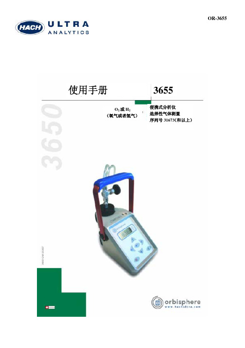
3655溶解氧测定仪中文操作手册H+O
3.3 保存测量数据
操作信息-3655 型记录仪
记录仪可以保存 500 个气体测量数据,编号从 0 到 499,同时记录了每次测量的当
前日期和时间。用户可以根据下面的描述,手动或者自动获得这些信息。
在保存测量数据以前,用户应当确定仪器间隔时钟的日期和时间设置,详细说明请
查阅第 38 页的“时间设置”。
Resistivity(电阻率) 当一稳定的电流通过某主体或物质时产生的抵抗力。
Concentration (浓度)
在气相或者液相介质中某种物质的相对含量。
声明 • Dacron, Delrin, Tedlar, Tefzel, 和Viton是DuPont的注册商标. • Halar是Ausimont U.S.A., Inc.的注册商标。 • Hastelloy是 Haynes International的注册商标。 • Kynar是The Pennwalt Corporation公司的注册商标。 • Monel是IMCO Alloys International, Inc.的注册商标。 • Saran是Dow Chemical Co.的注册商标。 • Swagelok是Swagelok Co.的注册商标。 • Microsoft和Windows是Microsoft Corporation微软公司的注册商标。
3655 型记录仪-介绍
1 介绍
有关本使用手册 该本使用手册中的信息经过仔细的核查,确认为正确。但是,对于本使用手册中可 能包含的错误,哈希超纯分析不承担任何责任。由于手册中的错误或者忽略引起的 直接、间接、特定、偶然、或者必然的损失,哈希超纯分析不承担责任。哈希超纯 分析任何时候持有对本书及其描述的产品进行改善的权利,而无需通知或者承担义 务。 本手册中的设备序列号 本使用手册适用于下列设备: ·奥比斯菲亚 3655 型氧气分析仪;序列号 31673 或者大于此。 供应范围 检查包括在运送范围内的安装硬件(根据运送货单列表)。
Binder BD 115 标准自然通风炉说明书
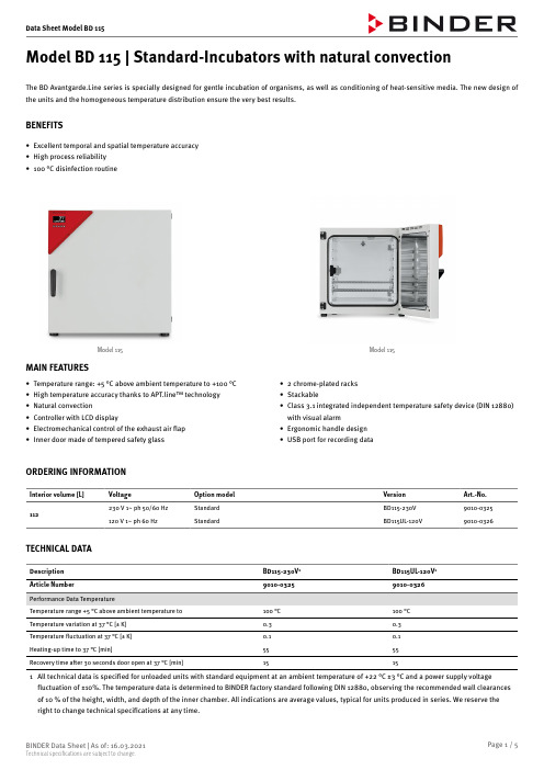
Model BD 115 | Standard-Incubators with natural convectionThe BD Avantgarde.Line series is specially designed for gentle incubation of organisms, as well as conditioning of heat-sensitive media. The new design of the units and the homogeneous temperature distribution ensure the very best results.BENEFITS•Excellent temporal and spatial temperature accuracy•High process reliability•100 °C disinfection routineModel 115Model 115MAIN FEATURES•Temperature range: +5 °C above ambient temperature to +100 °C•High temperature accuracy thanks to APT.line™ technology•Natural convection•Controller with LCD display•Electromechanical control of the exhaust air flap•Inner door made of tempered safety glass•2 chrome-plated racks•Stackable•Class 3.1 integrated independent temperature safety device (DIN 12880)with visual alarm•Ergonomic handle design•USB port for recording dataORDERING INFORMATIONInterior volume [L]Voltage Option model Version Art.-No.230 V 1~ ph 50/60 Hz Standard BD115-230V9010-0325112120 V 1~ ph 60 Hz Standard BD115UL-120V9010-0326 TECHNICAL DATADescription BD115-230V1BD115UL-120V1Article Number9010-03259010-0326Temperature variation at 37 °C [± K]0.30.3Temperature fluctuation at 37 °C [± K]0.10.1Heating-up time to 37 °C [min]5555Recovery time a er 30 seconds door open at 37 °C [min]15151All technical data is speci ed for unloaded units with standard equipment at an ambient temperature of +22 °C ±3 °C and a power supply voltage fluctuation of ±10%. The temperature data is determined to BINDER factory standard following DIN 12880, observing the recommended wall clearances of 10 % of the height, width, and depth of the inner chamber. All indications are average values, typical for units produced in series. We reserve the right to change technical speci cations at any time.Description BD115-230V1BD115UL-120V1Article Number9010-03259010-0326Power frequency [Hz]50/6060Nominal power [kW]0.350.35Unit fuse [A] 6.312.5Phase (Nominal voltage)1~1~Net weight of the unit (empty) [kg]5757Permitted load [kg]150150Load per rack [kg]3030Wall clearance back [mm]160160Wall clearance sidewise [mm]100100Height [mm]530530Depth [mm]420420Height net [mm]705705Depth net [mm]6056051All technical data is speci ed for unloaded units with standard equipment at an ambient temperature of +22 °C ±3 °C and a power supply voltage fluctuation of ±10%. The temperature data is determined to BINDER factory standard following DIN 12880, observing the recommended wall clearances of 10 % of the height, width, and depth of the inner chamber. All indications are average values, typical for units produced in series. We reserve the right to change technical speci cations at any time.DIMENSIONS incl. ttings and connections [mm]OPTIONSDesignationDescription*Art.-No.back 10 mm 018012-039030 mm 018012-039750 mm 018012-0399le 10 mm 018012-038830 mm 018012-004750 mm018012-0051right 10 mm 018012-038730 mm 018012-004650 mm 018012-0050top 10 mm 018012-038630 mm 018012-004550 mm 018012-0049Access port with silicone plug100 mm018012-0053Alarm function for overheatingSwitchable acoustic alarm, with adjustable limit value on the independent temperature safety device –8012-0979Analog output 4-20 mA for temperature values (output not adjustable)028012-0941Calibration certi cate,expandedfor temperature; for extending the measurement in center of chamber to include another test temperature –8012-1110for temperature, measurement in center of chamber at speci ed temperature–8012-1129temperature measurement incl. certi cate and 27 measuring points at speci ed temperature –8012-0921temperature measurement incl. certi cate, 15- 18 measuring points at speci ed temperature –8012-0918Calibration certi cate,temperaturetemperature measurement incl. certi cate, 9 measuring points at speci ed temperature–8012-0915Clock battery-backed –8012-0981Door lock lockable door handle–8012-1025Ethernet interface for Multi Management So ware APT-COM™–8012-0986Interior socket Waterproof, switched flush-mounting box (CA3GD) for nominal voltage in unit interior, with cover and corresponding plug (nominal voltage; max. 500 W; max. 90 °C; protection class IP67)–8012-0980Pt 100 temperature sensoradditional flexible Pt 100, interior, for displaying the temperature on the unit display–8012-0940* Notes › See last pageACCESSORIESDesignationDescription*Art.-No.for simple logging and documentation requirements with up to 5 networked units.APT-COM™ 4 BASIC-Editionversion 4, BASIC edition–9053-0039for working under GLP-compliant conditions. Measured values are documented in a tamper-proof way in line with the requirements of FDA Regulation 21 CFR 11.APT-COM™ 4 GLP-Editionversion 4, GLP edition–9053-0042convenient unit and user management built on the BASIC edition. Suitable for networking up to 100 units.APT-COM™ 4PROFESSIONAL-Edition version 4, PROFESSIONAL edition–9053-0040Data Logger Kit T 220: For continuous temperature logging from -90 °C to 220 °C. The kit includes 1 data logger, Pt 100 sensor with 2 m extension cable and 1 magnetic xture for mounting to the BINDER unit–8012-0715Data Logger So ware LOG ANALYZE so ware kit, con guration and evaluation so ware for all BINDER Data Logger Kits (incl. USB data cable)–8012-0821pH-neutral detergentconcentrated, for gentle remove of residual contaminants; 1 kg–1002-0016* Notes › See last pageDesignation Description*Art.-No.IQ/OQ documents – supporting documents for validation performed by customers, consisting of: IQ/OQ checklists incl.calibration guide and comprehensive unit documentation; parameters: temperature, CO2, O2, pressure, depending onunitDigital in PDF format–7057-0001Hard copy inside folder–7007-0001IQ/OQ/PQ documents – supporting documents for validation performed by customers, according to customerrequirements, PQ section added to quali cation folder IQ/OQ; parameters: temperature, CO2, O2 – or pressure,depending on unitDigital in PDF format–7057-0005 Quali cation documentsHard copy inside folder–7007-0005chrome plated–6004-0175 Rackstainless steel–6004-0159 Rack, heavy load Stainless steel, max. load per rack 70 kg–6004-0251 Rubber pads set anti-slip feet–8012-1887 Shelf, perforated Stainless steel–6004-0191 Table on castors stable cart, casters with locking brakes, dimensions: W 1,000 x D 800 x H 780 mm–9051-0018 * Notes › See last pageSERVICESDesignation Description*Art.-No.Unit commissioning check, brief operating instructions. (excl.: unpacking, setup, controller instructions, programming,installation work)05DL10-0100Unit instructions Instruction regarding operating principle and basic functions of the unit, operation of the controlelectronics including programming05DL10-0500BRONZE 3-year maintenance contract check of control response, 20% discount on spare parts05DL20-0710GOLD 3-year maintenance contract Maintenance service as contractually agreed, visual inspection of mechanical and electrical components,check of control response, 20% discount on spare parts, testing of all key functions, replacement ofwear parts, calibration of one test temperature speci ed by the user in the center of the usable space,including certi cate05DL20-0910Maintenance One-o maintenance service in accordance with maintenance schedule. Visual inspection of mechanicaland electrical components, testing of all key functions. Calibration of a test temperature speci ed by theuser in center of usable space without certi cate05DL20-0200SILVER 3-year maintenance contract Maintenance service as contractually agreed, visual inspection of mechanical and electrical components, check of control response, 20% discount on spare parts, testing of all key functions, calibration of onetest temperature speci ed by the user in the center of the usable space, without certi cate05DL20-0810Calibration of one (1) test temperature speci ed by the user in center of chamber, including certi cate05DL30-0101Calibration certi cate, temperatureExtension of calibration of one (1) additional test temperature speci ed by the user in the center of theusable space, including certi cate 03, 04,05DL30-0102Temperature measurement, 18 measuring points Temperature measurement with 18 measuring points with a set value speci ed by the user, includingcerti cate03, 04,05DL30-0118Temperature measurement, 27 measuring points Temperature measurement with 27 measuring points with a set value speci ed by the user, includingcerti cate03, 04,05DL30-0127Temperature measurement, 9 measuring points Temperature measurement with 9 measuring points with a set value speci ed by the user, includingcerti cate03, 04,05DL30-0109 Execution of IQ/OQ/PQ Execution of IQ/OQ/PQ in accordance with quali cation folder05DL44-0500 * Notes › See last pageNOTES01Condensation may occur in the area around the access port. Access ports may be placed in custom locations for an additional charge.02UL mark is not granted when this option is used.03Sensor calibration is performed in an accredited calibration laboratory.04Calibration is performed according to the BINDER factory standard.05Quoted prices do not include travel costs. Please refer to the chapter on BINDER Service for travel costs for your region. Quoted prices for services performed in Switzerland do not include a country-speci c added fee (available on request).BINDER GmbH Tuttlingen, Germany TEL +49 7462 2005 0 FAX +49 7462 2005 100 ********************* BINDER Asia Paci c (Hong Kong) Ltd.Kowloon, Hong Kong, P.R. ChinaTEL +852 ********FAX +852 *****************************Representative O ce for CISMoscow, RussiaTEL +7 495 988 15 16FAX +7 495 988 15 17***********************BINDER Environmental TestingEquipment (Shanghai) Co., Ltd.Shanghai, P.R. ChinaTEL +86 21 685 808 25FAX +86 21 685 808 29**********************BINDER Inc.Bohemia, NY, USATEL +1 631 224 4340FAX +1 631 224 4354********************。
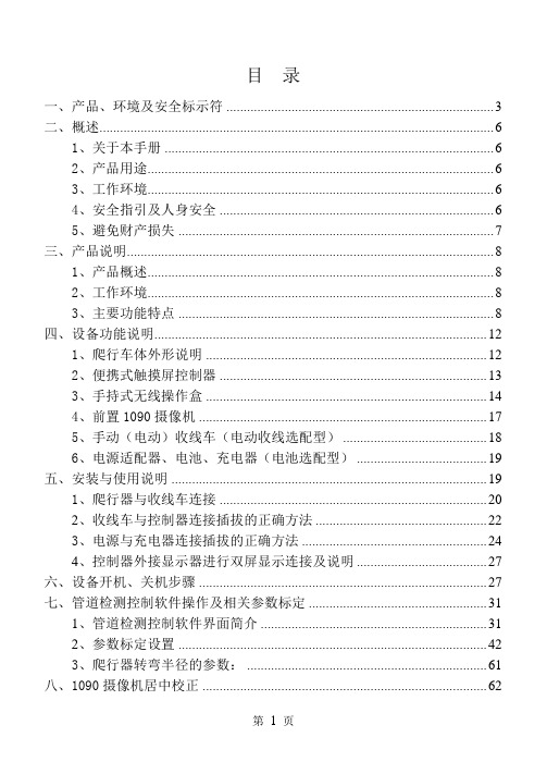
施罗德爬行机器人S200中文说明书
11)防水等级:IP54
手动(电动)收线车(电动收线选配型)
1)线缆测量:电子计米,距离可直接显示在监视器屏幕上;精确定位,测量最小距离精度可达±。
2)线缆长度:线缆直径7.9mm,标准配置120米,可根据用户要求配置长度;
线缆防水、防油、耐磨、耐腐蚀。
3)驱动:电动或手动收、放线。
危险警告符号:表示一些存在危险情况的环境,如果不能避免,将导致死亡和严重的伤害事故。
警告符号:表示危险的境况,如果不能避免,也可能导致死亡或严重的伤害事故。
小心符号:表示危险的境况,如果不能避免,可能导致轻微或中等程度伤害事故。
注意符号:表示和保护财产相关的安全信息,该符号意味着使用者在使用该工具前必须仔细阅读操作手册,因为操作手册里介绍了重要的安全注意事项和正确的使用方法。
2、产品用途
CCTV管道检测爬行系统主要用于市政排水管道内部快速检测和诊断。该设备配备强力照明光源和便携式控制系统,适合野外和移动工作场所。传输线缆可以根据用户需求配备,目前最长支持500米(光纤通信线缆),可将设备送至所需工作位置。爬行车部件采用防水设计可至水下检测(正压状态下),但实际操作根据水下环境而定。
安全气压检测系统:
自动检测车体、摄像系统、升降系统内部气体压力,并实时向后端设备传送数据、并能自动判断和处理异常,确保设备及工作环境的安全(下井前需充入大约10~14PIS干燥气体)。
4、主要技术参数
爬行系统:9902FA
1)适用于150mm(最小轮)以上的管道检测,配置大小轮胎及电动升降台。
2)爬行器工作电压48V,最大输出功率180W。
用户使用发电机供电时,请严格按照发电机的操作规程执行,并且能够适用本公司自带的稳压适配器!
- 1、下载文档前请自行甄别文档内容的完整性,平台不提供额外的编辑、内容补充、找答案等附加服务。
- 2、"仅部分预览"的文档,不可在线预览部分如存在完整性等问题,可反馈申请退款(可完整预览的文档不适用该条件!)。
- 3、如文档侵犯您的权益,请联系客服反馈,我们会尽快为您处理(人工客服工作时间:9:00-18:30)。
保护功能可编程
装置具有保护功能逻辑编程功能,使得保护的适用性和灵活性大大提高。 特别是对石化、冶金、供水等现场控制要求较复杂的工厂用户,常规保护项 目往往不能完善彻底地解决实际应用,保护功能的逻辑方程式则完全可以满 足要求,避免订制非标产品的做法。
通用化设计
同一结构的产品不因型号而改变外部接口, 不同型号之间的区别仅在于保 护程序不同,不仅方便设计画图,而且方便用户接线和维护。
4
● ●
4
● ● ● ●
2
珠海施诺电力科技有限公司
装置型号与功能对照表
5 6 7 8 9 10 记 录 通讯 1 2 3
功率因数 频率 有功、无功电度 故障录波 谐波分析 模拟量输出 保护事件记录 跳闸电流 保护运行时间 RS485
● ● ● ● ● ○ ● ● ● ● ● ● ●
● ● ● ● ● ○ ● ● ●
珠海施诺电力科技有限公司
产品系列划分;特点
1、Ⅵ型微机保护及自动装置
1.1、Ⅵ型产品系列划分及适用范围
产品名称 发电机保护 变压器保护 电动机保护 线路保护 电容器保护 PT 监控、保护 PT 并列、切换 备自投 产品系列 S36xG 系列 S36xT-1 S36xT-2 S36xT-3 S36xM 系列 S36xL 系列 S36xC 系列 S36xU 系列 S36xP 系列 S36xB 系列 适用范围 一般 100MW 以下发电机组 110kV 变压器 35~66kV 变压器 6~10kV 变压器 6~10kV 电动机 6~110kV 线路 6~35kV 电容器 6~110kV 母线电压互感器 6~110kV 母线电压互感器 0.4~110kV 主备供电系统
公司简介
珠海施诺电力科技有限公司是一家专业从事开发、 生产、销售微机型继电保护装置、智能化电气测量监控 仪表和变电站综合自动化系统的合资公司。 公司主要设有研发、生产、质检、工程、经营等部 门,拥有先进的生产、检验设备和优秀的专业人才,实 行科学化、制度化的管理。 多年来我们一直致力于自动控制技术和计算机技术 与电力系统应用相结合的研究和产品开发,在继电保护 及电力监控综合自动化方面积累了丰富的理论和实践经 验,并开发出了适合中国国情的电力自动化产品。 本公司的微机保护等系列化产品硬件平台先进、软 件设计灵活,在适应不同用户需求方面具有独到之处。 产品通过国家权威部门的检测,目前业已在国内外多种 行业、多个地区得到应用,运行情况良好。 公司总部位于珠海国家级高新技术产业园区—清华 科技园, 借助园区引导清华大学科研成果产业化的优势; 连接企业、大学、政府及社会资源的纽带作用;优良的 科技创新氛围;以及完善的专业化的服务于园区企业的 配套设施、机构,公司取得了长足进步及良性发展。 为了给广大用户提供方便快捷的服务, 我们在济南、 郑州、成都、兰州、沈阳、新疆、内蒙等多个城市设有 常驻办事机构,开展技术咨询、商务洽谈、售后服务等 工作。 “诚信经营、质量第一”是我们的宗旨。我们一直 本着为用户负责的精神和态度,坚持为广大用户提供高 质量的产品和优良的服务。
1+①
1+①
1+①
说明:表中数字表示该功能的“段”数或个数; ● 标准配置; ○ 选择配置(订货时说明)。
珠海施诺电力科技有限公司
3
装置型号与功能对照表
1.3.2、110kV 及以上变压器保护
型号及名称 类 别 序 号 1 2 3 4 5 6 7 8 9 保 10 11 12 13 护 14 15 16 17 18 19 20 21 22 23 1 控 制 2 3 4 5 1 2 测 量 3 4 5 6 7 记 录 通讯 1 2 3 相电流 零序过流 负序/不平衡过流 热过载 方向过流 方向接地 复合电压闭锁过流 零序电压闭锁零序过流 低周减载 高频 断路器失灵 低电压 过电压 正序低电压 负序过电压 中性点电压偏移 间隙保护 变压器差动(双圈变) 零序差流 方向有功过功率 非电量(温度/瓦斯) 过流启动风冷/过流闭锁调压 非全相保护 遥控 控制设置 断线闭锁(CT/PT) 有载调压档位采集 逻辑方程式 相电流/零序电流 相电压/线电压/零序电压 有功、无功、视在功率/功率因数/频率 有功、无功电度 故障录波 谐波分析 模拟量输出 保护事件记录 跳闸电流 保护运行时间 RS485 60/60FL 功 能 ANSI 码 S365T-1 变压器后备 50/51 50N/51N 46 49RMS 67 67N/67NC 50&47/27 50N&59N 81L 81H 50BF 27/27S 59 27D 47 59N 51N&59N 87T 64REF 32P 26/63 50/51 1 1
目录
1、ⅤI型微机保护及自动装置
1.1 、Ⅴ I 型产品系列划分及适用范围………… ... …… ....1 1.2、产品特点…………….……………………...............1 1.3、装置型号与功能对照表 1.3.1、发电机保护….……....……………….…………2 1.3.2、110kV及以上变压器保护…….………………..4 1.3.3、35~66kV变压器保护………....…...………….5 1.3.4、6~10kV变压器保护…………………….…….6 1.3.5、 电动机保护…………...........……………………7 1.3.6、线路、电容器保护……………......……............8 1.3.7、PT测控、保护及低压母线电压监测…...…..….9 1.3.8、自动装置(PT并列及备自投)……….....……10 1.4、 装置端子图………..................................……………11 1.5、 装置外形及安装开孔图………..…..………………….18 1.6、 接线…..……....…….……………..……………...……19 1.7、 保护定值整定范围….…....……..…….…………..…..23 1.8、 保护功能介绍.………………………..…..……….......25 1.9、控制功能介绍 1.9.1、 备自投……..……….............................………44 1.9.2、PT并列…….………………………..………….45 1.10、测量功能介绍………..…………….……….………..47 1.11、 记录及通讯功能介绍…………....……..……..……..48 1.12、产品设计标准………………………...…...…………49 1.13、通用技术参数、指标………………….……………..50 1.14、 订货须知……………………………..……..….……..52
● ● ● ● ● ● ● ●
S366G 发电机 差动保护
S367G 差动及后备 一体化 4 4 2 1 2 2 4 1 4 2 4 4 2 2 2 1
4 4 2 1 2 2 4 1 4 2 4 4 2 2 2 1 1 1
1 1 1 1 1 1 1 1 1 1 1 1 1 1
● ● ● ●
4
● ● ● ●
2、测控装置
2.1、概述…………...………………………….................53 2.2、装置型号与功能对照表..................…...…….………53 2.3、装置端子图………............................……….………54 2.4、装置外形及安装开孔图..……..…..…...……….…….56 2.5、选型及接线…..……....……………..………………56 2.6、功能介绍.……………………….…..……….……….57 2.7、订货须知……………………………………..….…..58
4
●
4
● ● ● ●
●
● ● ○
● ● ●
● ● ●
1+①
1+①
1+①
说明:表中数字表示该功能的“段”数或个数; ● 标准配置; ○ 选择配置(订货时说明)。
4
珠海施诺电力科技有限公司
装置型号与功能对照表
1.3.3、35~66kV 变压器保护
型号及名称 类 别 序 号 1 2 3 4 5 6 7 保 8 9 10 护 11 12 13 14 15 16 17 18 1 控 制 2 3 4 5 1 2 测 量 3 4 5 6 7 记 录 通讯 1 2 3 相电流 零序过流 负序/不平衡 热过载 方向过流 方向接地 复压闭锁过流 零序电压闭锁零序电流 低周减载/高频 断路器失灵 低电压/过电压 正序低电压 负序过电压 中性点电压偏移 差动(双圈变) 方向有功过功率 非电量 过流启风冷/锁调压 遥控 控制设置 CT/PT 断线闭锁 有载调压档位采集 逻辑方程式 相电流 零序电流 相/线/零序电压 有功、无功、视在功率/功率因数/频率 故障录波 谐波分析 模拟量输出 保护事件记录 跳闸电流 保护运行时间 RS485 60/60FL 功 能 ANSI 码 S365T-2 变压器 后备 50/51 50N/51N 46 49RMS 67 67N/67NC 50&47/27 50N&59N 81L/81H 50BF 27/27S/59 27D 47 59N 87T 32P 26/63 50/51 1
RTOS实时多任务操作系统
装置嵌入实时多任务操作系统,合理而有效地利用CUP资源,各种高级的 软件功能得以实现,提升装置的可靠性、实时性和稳定性。
灵活的参数设置
保护装置正确使用与现场其它设备(互感器、被保护设备本身等)的参数 密切相关,而这些参数只有到现场调试阶段才最终确定,因此需要保护装置 的参数设置具备灵活性,使其尽可能广泛地适用各种不同要求的场合。 例如:保护定值;功能投退;电流输入方式(A、C两相或三相)、额定值 (5A、1A)、变比;开入量含义、性质(跳闸或报警);出口继电器接点的 性质(自返回或自保持)等均可在现场按用户要求任意定义,不需要特制或 定制。
