ATS22 软启说明书
施耐德ATS22软启动器用户手册[1]
![施耐德ATS22软启动器用户手册[1]](https://img.taocdn.com/s3/m/d3d26d772a160b4e767f5acfa1c7aa00b52a9d99.png)
施耐德ATS22软启动器用户手册========================一、产品简介------------施耐德ATS22软启动器是一种用于控制三相异步电动机启动和停止的设备,它可以根据设定的参数,对电动机的电压进行平滑调节,从而实现电动机的柔和启动和停止,减少电网冲击和机械应力,提高设备的可靠性和寿命。
适用于额定功率为3至315千瓦的三相异步电动机。
内置了多种保护功能,如过载、过热、过流、短路、缺相、欠压、过压等。
支持多种控制方式,如本地控制、远程控制、串口通讯等。
支持多种工作模式,如标准模式、泵模式、扭矩控制模式等。
具有故障诊断功能,可以记录最近的四次故障信息,并提供故障代码和解决方法。
二、产品安装------------选择合适的安装位置,确保软启动器周围有足够的空间进行散热和维护。
按照软启动器的型号和电动机的额定电流,选择合适的电缆和接线方式。
按照软启动器上的接线图,将电源线、电动机线、控制线等正确地连接到软启动器上。
检查接线是否正确无误,无短路或接地故障。
通电后,检查软启动器上的显示屏是否正常工作,无故障提示。
三、产品参数------------ATS22软启动器有多种型号,其主要参数如下表所示:---型号 ---额定电流(A) ---额定功率(kW) ---尺寸(mm) -----------------------------------------------------------------ATS22D17S ---17 ---7.5 ---140x230x165 -------ATS22D32S ---32 ---15 ---140x230x165 -------ATS22D47S ---47 ---22 ---140x230x165 -------ATS22D62S ---62 ---30 ---140x230x165 -------ATS22D75S ---75 ---37 ---140x230x165 -------ATS22D88S ---88 ---45 ---140x230x165 -------ATS22C11S ---110 ---55 ---210x300x200 -------ATS22C14S ---140 ---75 ---210x300x200 -------ATS22C17S ---170 ---90 ---210x300x200 -------ATS22C21S ---210 ---110 ---210x300x200 -------ATS22C25S ---250 ---132 ---210x300x200 -------ATS22C32S ---320 ---160 ---210x300x200 -------ATS22C41S ---410 ---200 ---210x300x200 -------ATS22C48S ---480 ---250 ---210x300x200 -------ATS22C59S ---590 ---315 ---210x300x200 ----四、产品操作------------参数设置:通过液晶显示屏和按键,可以对软启动器的各种参数进行设置,如启动电压、启动时间、停止时间、工作模式、保护功能等。
施耐德ATS22软启动器使用说明
施耐德ATS22软启动器使用说明ATS22软起动器是由施耐德公司生产的一种电气设备,用于控制和保护三相异步电动机的启动。
本文将详细介绍ATS22软启动器的使用说明。
一、ATS22软启动器的特点:1.启动器具有良好的过载保护功能,可保护电动机和电器设备。
2.采用软启动技术,可实现电动机的平稳启动和停止。
3.启动器具有小型、易安装、操作简单的特点。
4.启动器具有先进的保护和监控功能,可确保电动机的安全运行。
二、ATS22软启动器的安装:1.在进行安装前,请确保设备和电源已经断开。
2.安装软启动器时,要保证启动器的散热良好,不要堵塞散热孔。
3.软启动器的安装位置应远离易燃易爆或尘埃大的场所,并且避免遭受直射阳光。
4.安装时,请确保该电气设备符合国家和地方的安全规范。
三、ATS22软启动器的操作:1.ATS22软启动器具有一键启动和停止的功能,操作非常简单。
2.对于连续启动和停止的情况,可以接通保持回路来实现一键连续启动和停止的功能。
3.在启动和停止过程中,请确保电源的稳定,以避免电动机受损。
4.在启动和停止之前,最好先观察和检查周围环境和电动机的运行状态,以确保安全。
四、ATS22软启动器的保护功能:1.过载保护:当电动机负载超过额定电流时,启动器会自动停止电动机,保护电动机和电器设备。
2.电流过高保护:当电动机负载过大或启动电流过高时,启动器可以检测到,并自动停止电动机。
3.过温保护:当电动机或启动器内部温度过高时,启动器会自动停止电动机,并发出警报信号。
4.短路保护:当电动机出现短路故障时,启动器会自动断开电源,避免故障扩大。
5.断相保护:当电动机供电的任何一相中断时,启动器会立即停止电动机。
五、ATS22软启动器的维护:1.定期清洁软启动器的散热孔,以确保良好的散热效果。
2.定期检查启动器的接线情况,确保电源和电动机的接线正常。
3.定期检查启动器的保护功能是否正常,如过载保护、过温保护等。
4.在启动器长时间不使用时,应将其存放在干燥的地方,避免受潮或损坏。
施耐德ATS22软启动器使用说明

施耐德ATS22软启动器使用说明一、硬件安装1.施耐德ATS22软启动器应固定在安装板上,并通过适当长度的导轨固定在控制柜内。
2.电源线、电机线和控制线需按照规定的接线方法进行接线,确保安全可靠。
3.在安装过程中,应注意避免强电线路与弱电线路的相互干扰,避免引起故障。
二、参数配置1.在使用之前,应先对施耐德ATS22软启动器的参数进行配置。
2.配置参数包括电压、电流、启动方式、停止方式等,根据实际需求进行设置。
3.可通过编程软件或面板按键对参数进行配置,参数设置后需保存。
三、启动与停止1.启动:在配置好参数后,按下启动键,软启动器会根据配置参数进行相应的启动过程。
2.停止:按下停止键即可停止电动机的转动。
3.在运行过程中,可以通过面板按键或远程控制进行启动和停止的操作。
四、维护与保养1.定期检查:定期检查施耐德ATS22软启动器的连接线路是否松动,检查电源线、电机线和控制线的接线是否正常。
2.清洁保养:定期对软启动器进行清洁保养,确保设备的可靠性。
3.注意事项:在维护保养过程中,需要切断电源,确保安全操作。
五、故障排除1.施耐德ATS22软启动器使用过程中可能出现故障,可根据显示屏上的故障代码和说明进行排除。
2.常见故障包括过载、过热、短路等,应按照指示进行处理,确保设备的正常运行。
施耐德ATS22软启动器的使用说明以上述内容为主进行详细介绍,通过硬件安装、参数配置、启动与停止、维护与保养以及故障排除等方面的说明,用户可以更好地了解和使用施耐德ATS22软启动器,确保设备的正常运行。
同时,用户在使用过程中应注意安全操作,保持设备的良好状态。
ATS22施耐德软启动操作流程
ATS22施耐德软启动操作流程引言:一、ATS22软启动器的组成与功能ATS22软启动器主要由主控模块、电源模块、保护模块等部分组成。
主控模块通过控制电路和触摸屏操作,实现对电机的启动、停止、设定转速等功能;电源模块为整个设备提供电能供给;保护模块用于监测电机的运行状态,一旦发生异常情况,如电压过高、电流过载等,保护模块会及时切断电源,从而保护电机的安全运行。
二、软启动器的操作流程1.准备工作:a.确保电源供应稳定,并连接好ATS22软启动器;b.检查起动电机的线路接线是否正确;c.检查软启动器的参数设置是否符合实际要求。
2.启动操作:a.打开ATS22软启动器的电源开关,主控模块开始运行;b.在触摸屏上选择启动模式,如手动、自动等;c.设置电机的额定电流、启动电流、启动时间等参数;d.通过触摸屏或外部控制信号启动电机;e.主控模块将依次开启软启动器的接触器,逐步使电机达到设定的启动电流和转速;f.一旦电机达到设定的转速,主控模块将维持设定状态,并进入运行模式。
3.运行操作:a.在转速控制模式下,主控模块可以通过触摸屏或外部控制信号改变电机的转速;b.在保护模式下,保护模块会实时监测电机的电压、电流等参数,一旦发生异常情况,如过载、过热等,保护模块会及时切断电源,避免损坏电机;c.在停机模式下,通过触摸屏或外部控制信号停止电机的运行。
4.停机操作:a.在通常情况下,可以通过触摸屏或外部控制信号停止电机的运行;b.在紧急情况下,如电源故障、电机过热等,软启动器会自动切断电源,停止电机运行。
5.维护操作:a.定期检查ATS22软启动器的运行状态,如触摸屏的响应速度、运行指示灯;b.定期检查软启动器的接线是否松动,紧固螺丝是否正常;c.定期清洁软启动器的外壳,并及时更换老化的部件,如保护模块。
三、易错点与应对措施1.启动电机时,发现软启动器没有反应:a.检查电源线路是否通电;b.检查软启动器的开关是否打开。
ATS22快速入门
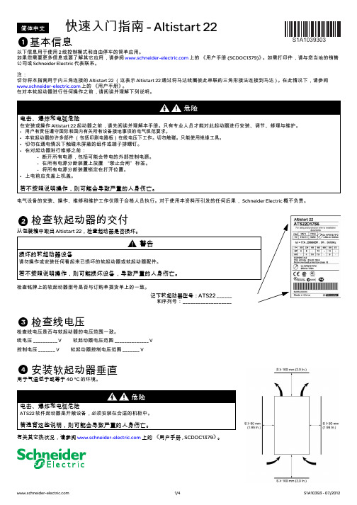
有关其它热状况,请参阅 上的 《用户手册 , SCDOC1379》。
1/4
S1A10393 - 07/2012
连接软起动器
⁄„ı⁄
1L1 3L2 5L3
检查软起动器的交付
从包装箱中取出 Altistart 22,检查起动器是否损坏。
警告
损坏的软起动器设备
请勿操作或安装任何看起来已损坏的软起动器或软起动器配件。
若不按照说明操作,则可能损坏设备,导致严重的人身伤亡。
检查铭牌上的软起动器型号是否与订购单提货单上的一致。
记下软起动器型号:ATS22 ______ 和序列号:___________________
调整 UIn 线电压
• 按 按钮,至 conF 菜单。 • 按 按钮。 • 按 按钮,至 UIn 参数。 • 利用向上滚动或向下滚动按钮,将 UIn 设置为电源电压交流值。 • 按 按钮以验证 UIn 值。
给 Altistart 22 通电并启动电机
• 盖上机盖。 • 按 S2 按钮。 • 软起动器显示 rdY。 • 闭合 S3,电机启动。
适用于 ATS22pppQ 或 ATS22pppS6 2 线控制,自由停车
Rdy Com Run Trip
a) 连接电源回路:
- 将软起动器接地。 - 将软起动器连接到线电源:1/L1 – 3/L2 – 5/L3。 - 检查电机电压是否与软起动器电压一致。 - 将软起动器连接到电机。
2T1 4T2 6T3 ⁄„ı⁄
U1 V1 W1
Motor
M1 3
(1) 检查触点的操作限制。 (2) 根据电源电压选择变压器。
b) 连接控制回路:
施耐德ATS22软启动器使用说明
决方案融合在一个统一的架构下 , 通过标准的界面为各行业客户提供一个开放
、 透明 、 节能 、 高效的
能效管理平台 ,为企业客户节省高达 30 % 的投资成本和运营成本 。
目录
重要信息 ___________________________________________________________________________________________________________________4 开始之前 ___________________________________________________________________________________________________________________5 文档结构 ___________________________________________________________________________________________________________________6
软起动器设置步骤 ( 另参见 “快速起动”指南 ) ____________________________________________________________________ 7
接收和搬运 _________________________________________________________________________________________________________________8 选型 _____________________________________________________________________________________________________________
ATS22 Soft Start-Soft Stop Unit User Manual

B B V 51330 Altistart 22Soft start - soft stop unitUser manual01/2014The information provided in this documentation contains general descriptions and/or technical characteristics of the performance of the products contained herein. This documentation is not intended as a substitute for and is not to be used for determining suitability or reliability of these products for specific user applications. It is the duty of any such user or integrator to perform the appropriate and complete risk analysis, evaluation and testing of the products with respect to the relevant specific application or use thereof. Neither Schneider Electric nor any of its affiliates or subsidiaries shall be responsible or liable for misuse of the information contained herein. If you have any suggestions for improvements or amendments or have found errors in this publication, please notify us. No part of this document may be reproduced in any form or by any means, electronic or mechanical, including photocopying, without express written permission of Schneider Electric.All pertinent state, regional, and local safety regulations must be observed when installing and using this product. For reasons of safety and to help ensure compliance with documented system data, only the manufacturer should perform repairs to components. When devices are used for applications with technical safety requirements, the relevant instructions must be followed.Failure to use Schneider Electric software or approved software with our hardware products may result in injury, harm, or improper operating results.Failure to observe this information can result in injury or equipment damage.© 2013 Schneider Electric. All rights reserved.ContentImportant Information__________________________________________________________________________________________ 4Before you begin______________________________________________________________________________________________ 5Documentation structure________________________________________________________________________________________ 6Steps for setting up the soft starter (also refer to Quick Start guide)__________________________________________ 7 Receiving and handling________________________________________________________________________________________ 8Selection___________________________________________________________________________________________________ 10Dimensions and weights_______________________________________________________________________________________ 14Mounting___________________________________________________________________________________________________ 17Mounting - Fan option_________________________________________________________________________________________ 20Thermal protection___________________________________________________________________________________________ 22Wiring_____________________________________________________________________________________________________ 26Wiring - power terminals_______________________________________________________________________________________ 32Wiring - control terminals______________________________________________________________________________________ 35Wiring - in line connection - application diagram____________________________________________________________________ 38Display terminal_____________________________________________________________________________________________ 42Remote keypad display - option_________________________________________________________________________________ 44Programming_______________________________________________________________________________________________ 45List of parameters____________________________________________________________________________________________ 48Parameter settings___________________________________________________________________________________________ 49Configuration menu (ConF)____________________________________________________________________________________ 50Settings menu (SEt)__________________________________________________________________________________________ 51Advanced adjustments menu (AdJ)______________________________________________________________________________ 53Advanced settings menu (SEt2)_________________________________________________________________________________ 55Advanced protections menu (PrO)_______________________________________________________________________________ 56Advanced IO menu (IO)_______________________________________________________________________________________ 60Advanced communication menu (COP)___________________________________________________________________________ 62Advanced monitoring menu (SUP)_______________________________________________________________________________ 63Utility menu (UtIL)____________________________________________________________________________________________ 64Command channel___________________________________________________________________________________________ 65Modbus Function____________________________________________________________________________________________ 68Connection to RS485 bus______________________________________________________________________________________ 73Maintenance________________________________________________________________________________________________ 74Diagnostics / Troubleshooting__________________________________________________________________________________ 75Parameter Index and Modbus addresses__________________________________________________________________________ 77Annex 1: UL508 schematics____________________________________________________________________________________ 82Important InformationNOTICERead these instructions carefully, and look at the equipment to become familiar with the device before trying to install, operate, or maintain it. The following special messages may appear throughout this documentation or on the equipment to warn of potential hazards or to call attention to information that clarifies or simplifies a procedure.PLEASE NOTEElectrical equipment should be installed, operated, serviced, and maintained only by qualified personnel. No responsibility is assumed by Schneider Electric for any consequences arising out of the use of this product.© 2013 Schneider Electric. All Rights Reserved.NOTICENOTICE, used without the safety alert symbol, indicates a potentially hazardous situation which, if not avoided, can result in equipment damage.The addition of this symbol to a Danger or Warning safety label indicates that an electrical hazard exists, which will result in personal injury if the instructions are not followed.This is the safety alert symbol. It is used to alert you to potential personal injury hazards. Obey all safety messages that follow this symbol to avoid possible injury or death.Before you beginRead and understand these instructions before performing any procedure with this soft starter.(1)For additional information, refer to NEMA ICS 1.1 (latest edition), “Safety Guidelines for the Application, Installation, and Maintenanceof Solid State Control”.Documentation structureThe following Altistart 22 technical documents are available on the Schneider Electric website (). User manualThis manual describes how to install, commission, operate, and program the soft starter.Quick Start guideThis document (S1A10388) is delivered with the soft starter, and you can download it on . Quick Start annexAnnex for UL508 with SCCR (Short Circuit Current Ratings) and branch circuit protection).This document (S1A14738) is delivered with the soft starter, and you can download it on .Steps for setting up the soft starter (also refer to Quick Start guide)1. Receive and Inspect the soft starter vCheck that the soft starter reference on the nameplate is similar to thepurchase order.v Remove the Altistart 22 from packaging and check that it has not beendamaged2. Check the line voltage compatibility v Check that the line voltage, and control voltage arecompatible with the soft starter (pages 11 to 13).3. Mount the soft starter vertically v Mount the soft starter in accordance with theinstructions in this document (page 17).4. Wire the soft starter (page 29)v Connect the motor, ensuring that itsconnections correspond to the voltage.v Connect the line supply, after makingsure that the power is off.v Check and Connect the control supplyon CL1-CL25. Configure the soft starter(page 45)v Power on control, and do not givea start command.v Adjust UIn line voltage.v Adjust In motor rated current.6. StartSteps 1 to 4 areperformed withthe power off .IntroductionThe ATS22 offers acceleration and deceleration control of standard three-phase asynchronous induction (squirrel cage) motors. The ATS22controls the motor performance based on the motor torque rather than simple voltage or current based control. Advanced control algorithms are incorporated to help smooth rotation throughout the starting ramp and reducing mechanical instability at the end of starting.A digital keypad display is provided for soft starter setup and motor performance display.The ATS22 is available in 15 rated currents from 17 to 590A. ATS22 are rated for use from 208 to 600V motors, and are self-adjusting for a 50Hz or 60Hz supply frequency.This user manual covers the technical characteristics, specifications, installation, wiring, programming, and troubleshooting of ATS22.TerminologySome of the terms and acronyms used in this manual are defined in the table below:Receiving and Preliminary InspectionBefore installing the ATS22 soft starter, read this manual and follow all precautions.Before removing the ATS22 soft starter from its packing material, verify that the packing carton is not damaged from shipping. Damage to the packing carton usually indicates improper handling. If any damage is found, notify the carrier and your Schneider Electric representative.After removing the ATS22 soft starter from its packaging, inspect it for damage. If any shipping damage is found, notify the carrier and your sales representative. Verify that the ATS22 soft starter nameplate and label conform to the packing slip and corresponding purchase order.Storing and ShippingIf the ATS22 soft starter is not being immediately installed, store it in a clean, dry area where the ambient temperature is between -25 °C and +70 °C (-13 °F and +158 °F).If the ATS22 soft starter must be shipped to another location, use the original shipping material and carton to help protect it.Soft starter catalog numbersCatalog numbers are composed with:(1)The range is composed of 5 physical frame sizes distributed in 15 ratings from D17 to C59 (see page 11).TermDefinition Soft starter FLA Soft starter Full Load Amps This value is on the soft starter nameplate IcL.IcL : Soft starter rated currentMotor FLA Motor Full Load AmpsThis value is on the motor nameplate.The rated current of an induction motor at rated speed and load.Soft starter in line connection: In = rated current of the motor FLA.Soft starter inside delta connection: In = rated current of the motor FLA / 3.OCPDOvercurrent protective device. Soft starter rating (1)Power and control voltageProduct symbol 230-440V, 230Vac control supply, 24Vdc logic inputs 208-600V, 230Vac control supply, 24Vdc logic inputs 208-600V, 110Vac control supply, 110Vac logic inputsHandling the soft starterHoisting the ATS22The ATS22 range comprises 5 frame sizes, with various weights and dimensions.Small soft starters can be removed from their packaging and installed without a handling device. A handling device must be used from ATS22C21ppp to ATS22C59ppp; for this reason they are supplied with lifting holes.Do not remove the ATS22 from the carton until it is at the final installation site. Handlethe soft starter carefully after removing it from the carton to avoid damage to theinternal components, frame, or exterior. Once removed from the carton, the soft startercan be handled:•With a hoist. When hoisting the soft starter, attach a spreader bar to the twolifting holes on top as shown below.•In a horizontal position, with the back of the soft starter resting on a pallet.45°maxiPackage content•Soft starter•Quick Install guide•Package of screws for frame sizes C, D, and E•Allen key, supplied with size B productsSelectionSoft starter selectionS1 motor duty corresponds to starting followed by operation at constant load enabling the thermal stability to be reached.S4 motor duty corresponds to a cycle comprising starting, operation at constant load, and an idle period. This cycle is characterized by a load factor.The Altistart 22 must be selected depending on the type of application ("standard" or "severe") and the nominal power of the motor."Standard" or "severe" applications define the limiting values of the current and the cycle for motor duties S1 and S4. These duties are described in the IEC 60034-1.Standard applicationExample: centrifugal pumpIn standard application, the Altistart 22 is designed to provide:• in S1 duty: starting at 3.5 In for 40seconds from a cold state.• in S4 duty: a load factor of 90% and n starts per hour (see table below), with 3.5 In for 20seconds or an equivalent thermal cycle.In this case, the motor thermal protection must conform to protection class 10.:(1) Note: in case of both soft starts and soft stops, the number of starts has to be divided by 2.Severe applicationThe Altistart 22 rated current is limited to 3.5 IcL , see table page 19.IcL is the nominal current of the Altistart 22. If the application requires a higher rated starting current (> 3.5 IcL ), the soft starter must be oversized. See soft starter selection table, page 11.Soft starter sizing according to thermal protection class* Nominal = nominal size of the soft starter according to the nominal motor current (Motor FLA).** Nominal + 1 = oversize the soft starter by one rating compared to the nominal motor current (Motor FLA).*** Nominal + 2 = oversize the soft starter by 2 ratings compared to the nominal motor current (Motor FLA).FramesizeIn S4 duty, number ofstarts (1) per hourStandard With fanA 610B 610C 410D NA 4E NA 4Starting current Protection classClass 10Class 20Class 30y 3.5In max starting time Nominal*16s Nominal + 1**32s Nominal + 2*** 48ssoft starter in line connectionThe nominal motor current In must not exceed the maximum permanent current in class 10.See wiring page 30.Maximum surrounding temperatureThe information in the table above is based on operation at a maximum ambient temperature of 40 °C (104 °F) and mini. -10 °C (14 °F).The Altistart 22 can be used up to an ambient temperature of 60 °C (140 °F) as long as the max. permanent current in class 10 is derated by 2.2% for each degree above 40 °C (104 °F).Example: ATS22D32Q at 50 °C (122 °F) derated by 10 x 2.2% = 22%, 32A becomes 32 x (1-0.22) = 24.96A (max. nominal motor current).MotorAltistart 22ppp Q, 230/440 V (+ 10% - 15%) - 50/60 Hz (+/- 10%)Nominal motor power Motor nominal current In (Motor FLA)Soft starter rated current IcL (Soft starter FLA)Reference 230V 400V 440V kW kW kW A A 47.57.514.817ATS22D17Q 7.5151528.532ATS22D32Q 1122224247ATS22D47Q 1530305762ATS22D62Q 18.537376975ATS22D75Q 2245458188ATS22D88Q 305555100110ATS22C11Q 377575131140ATS22C14Q 459090162170ATS22C17Q 55110110195210ATS22C21Q 75132132233250ATS22C25Q 90160160285320ATS22C32Q 110220220388410ATS22C41Q 132250250437480ATS22C48Q 160315355560590ATS22C59Qsoft starter inside delta connectionOnly the Altistart 22ppp Q can be installed inside delta connection.(1)Line current is maximum 1.5 IcL . Also, the In setting must not exceed IcL .Example: for a 400V - 110kW motor with a line current of 195A, the minimum soft starter rated current,IcL = 195/1.5 = 130A. Thus select ATS22C14Q The nominal motor current In must not exceed the max. permanent current in class 10.See wiring page 26.Maximum surrounding temperatureThe information in the table above is based on operation at a maximum ambient temperature of 40 °C (104 °F) and mini. -10 °C (14 °F).The Altistart 22 can be used up to an ambient temperature of 60 °C (140 °F) as long as the max. permanent current in class 10 is derated by 2.2% for each degree above 40 °C (104 °F).Example: ATS22D32Q at 50 °C (122 °F) derated by 10 x 2.2% = 22%, 48A becomes 48 x 0.78 = 37.5A (max. nominal motor current).NOTICERISK OF DAMAGE TO THE MOTORATS22ppp S6 and ATS22ppp S6U must not be installed inside delta connection.Failure to follow these instructions can result in equipment damage.MotorSoft starter 230/440 V (+ 10% - 15%) - 50/60 Hz (+/- 10%)Nominal motor power Line current (Motor FLA) (1)In setting (Line current/3)Soft starter rated current IcL(soft starter FLA)Soft starterreference230V 400V 440V kW kW kW A A A 5.511152514.417ATS22D17Q 1122224827.732ATS22D32Q 18.545457040.447ATS22D47Q 2255559353.762ATS22D62Q 30557511264.775ATS22D75Q 37757513276.288ATS22D88Q 45909016595.3110ATS22C11Q 55110110210121.2140ATS22C14Q 15132132255147.2170ATS22C17Q 90160160315181.9210ATS22C21Q 110220220375216.5250ATS22C25Q 132250250480277.1320ATS22C32Q 160315355615355.1410ATS22C41Q 220355*********.7480ATS22C48Q 250400500885511.0590ATS22C59QStandard application, 208/600 V supply, soft starter in line connection(1)Value not indicated when there is no corresponding standardized motor.The nominal motor current In must not exceed the max. permanent current in class 10.Maximum surrounding temperatureThe information in the table above is based on operation at a maximum ambient temperature of 40 °C (104 °F) and mini. -10 °C (14 °F).The Altistart 22 can be used up to an ambient temperature of 60 °C (140 °F) as long as the max. permanent current in class 10 is derated by 2.2% for each degree above 40 °C (104 °F).Example: ATS22D32S6 at 50 °C (122 °F) derated by 10 x 2.2% = 22%, 27A becomes 27 x 0.78 =21.06A (max. nominal motor current).MotorSoft starter 208/600 V (+ 10% - 15%) 50/60 Hz (+/- 10%)Nominal motor power Motor nominal current In (Motor FLA)Soft starter rated current IcL (Soft starter FLA)Soft starter reference 208V 230V 230V400V 440V 460V 500V 575VHP HP kW kW kW HP kW HPA A 3547.57.5109151417ATS22D17S6 or S6U 7.5107.515152018.5252732ATS22D32S6 or S6U (1)151122223030404047ATS22D47S6 or S6U 15201530304037505262ATS22D62S6 or S6U 202518.537375045606575ATS22D75S6 or S6U 25302245456055757788ATS22D88S6 or S6U 3040305555757510096110ATS22C11S6 or S6U 405037757510090125124140ATS22C14S6 or S6U 5060459090125110150156170ATS22C17S6 or S6U 607555110110150132200180210ATS22C21S6 or S6U 7510075132132200160250240250ATS22C25S6 or S6U 10012590160160250220300302320ATS22C32S6 or S6U 125150110220220300250350361410ATS22C41S6 or S6U 150-(1)132250250350315400414480ATS22C48S6 or S6U (1)200160315355400400500477590ATS22C59S6 or S6UFor frame sizes D17 to D88, the fan is sold separately. (1)c: dimension of the product alone.c1: dimension of the product with its fan.(1) The voltage of the fan has to match the control voltage of the soft starter:ATS22ppp Q or ATS22ppp S6 Fan 230V (VW3G22ppp , ppp = 400 for size A, 401 for size B or 402 for size C)ATS22ppp S6U Fan 110V (VW3G22U ppp , ppp = 400 for size A, 401 for size B or 402 for size C)ATS22Framesizea b c c1e H Standard G With fanG1Dmm Weight mm (in.)mm (in.)mm (in.)mm (in.)mm (in.)mm (in.)mm (in.)mm (in.)mm (in.)kg (lb)D17A 130(5.1)265(10.4)169(6.6)209(8.2)6.5(0.3)250(9.8)100(3.9)65(2.6)7(0.28)5.5(12.1)D32A D47A D62B 145(5.7)295(11.6)207(8.1)247(9.7)10.5(0.4)276(10.9)115(4.5)80(3.15)7(0.28)7.8(17.2)D75B D88BFor frame sizes C11 to C17, the fan is sold separately. (1)c: dimension of the product alone.c1: dimension of the product with its fan.(1) The voltage of the fan has to match the control voltage of the soft starter:ATS22ppp Q or ATS22ppp S6 Fan 230V (VW3G22ppp , ppp = 400 for size A, 401 for size B or 402 for size C)ATS22ppp S6U Fan 110V (VW3G22U ppp , ppp = 400 for size A, 401 for size B or 402 for size C)ATS22Framesize Ca b c c1e H G1P Q Q1S D1D2D3Weight mm (in.)mm (in.)mm (in.)mm (in.)mm (in.)mm (in.)mm (in.)mm (in.)mm (in.)mm (in.)mm (in.)mm (in.)mm (in.)mm (in.)kg (lb)C11150(5.9)356(14)229.5(9)269.5(10.6)10.5(0.41)331(13)120(4.7)40.5(1.6)34.5(1.3)5(0.2)20(0.8)9(0.35)7(0.28)6(0.23)12.2(26.9)C14C17For frame sizes C21 to C59, the fan is integrated.ATS22Framesizea b c e H G1P Q Q1S D1D2Weightmm (in.)mm(in.)mm(in.)mm(in.)mm(in.)mm(in.)mm(in.)mm(in.)mm(in.)mm(in.)mm(in.)mm(in.)kg (lb)C21D206 (8.1)425(16.7)299(11.8)15(0.59)396(15.6)157(6.2)60(2.4)40(1.6)1.3(0.05)30(1.2)13.5(0.53)9(0.35)20.5(45.2)C25D C32D C41DC48E304(11.9)455(17.9)339.7(13.4)15(0.59)426(16.8)264(10.4)94(3.7)55(2.2)1(0.04)40(1.6)13.5(0.53)9(0.35)33(73.3)C59EMounting PrecautionsFollow these precautions when mounting the ATS22 soft starter:•The soft starter is compliant with pollution Degree 2 as defined in NEMA ICS1-1 or IEC 60664-1.•For environment pollution degree 3 install the product inside a cabinet type 12 or IP54.•The ATS22 soft starter generates heat and must be properly ventilated. Refer to "Thermal considerations for sizing enclosures” page 19 to determine power dissipated.•When several soft starters are installed in a control panel, arrange them in a row. Do not stack soft starters. Heat generated from the bottom soft starter can adversely affect the ambient temperature around the top soft starter.•Install the ATS22 vertically, within ± 10° (other positions are not allowed).•Do not place it close to heating elements. Leave sufficient free space so that the air required for cooling purposes can circulate from the bottom to the top of the unit.•Electrical current through the ATS22 will result in heat losses that must be dissipated into the ambient air immediately surrounding the soft starter. To help prevent a thermal fault, provide sufficient enclosure cooling and/or ventilation to limit the ambient temperature around the soft starter.S ≥ 100mm (3.9 in)S ≥ 50mm(1.95in.)S ≥ 50mm (1.95in.)Note: For the soft starters mounted side-by-side, the free space must be ≥ 50mm (1.95in.)S ≥ 100mm (3.9 in)Soft starter ventilationOn soft starters installed with a cooling fan, the fan is factory set to switch on automatically as soon as the heatsink temperature reaches 46 °C (114.8 °F).It is switched off when the heatsink temperature falls back to 43 °C (109.4 °F). This behavior can be modified by adjusting the FAn parameter in IO menu on page 61.Fan flow rates(1)Cubic Feet / MinuteMounting in a General Purpose Metal EnclosureObserve the mounting recommendations on the previous page.To help proper air circulation in the soft starter:•Install ventilation grilles.•Verify that ventilation is adequate: if not install a forced ventilation unit, with a filter if necessary.Derate the soft starter current IcL by 2.2% per °C for temperatures above 40 °C up to 60 °C (104 °F up to 140 °F).ReferenceFramesizeUnitStandard With optional fan kit 110V 230V 110V 230V ATS22 D17, D32, D47Am 3/hour--2831CFM (1)--1618ATS22 D62, D75, D88 B m 3/hour--2831CFM (1)--1618ATS22 C11, C14, C17C m 3/hour--108108CFM (1)--6464ATS22 C21, C25, C32, C41D m 3/hour148148--CFM (1)8787--ATS22 C48, C59E m 3/hour148148--CFM (1)8787--Mounting in a dust and damp-proof metal enclosureVentilation for dust and damp- proof enclosureFollow the instructions in this section in order to meet NEMA Type 12 (IP54) degree of protection.Do not use insulated or non-metallic enclosures as they have poor thermal conduction. Provide a stirring fan to circulate air inside the enclosure and to help prevent hot spots in the soft starter. This allows operation of the soft starter in an enclosure with a maximum internal temperature of 60 °C (140 °F). Ensure that the ambient temperature around the soft starters does not exceed this limit.Derate the soft starter current IcL by 2.2% per °C for temperatures above 40 °C up to 60 °C (104 °F up to 140 °F).Thermal considerations for sizing enclosuresWhen mounting the ATS22 soft starter in an enclosure, use the enclosure manufacturers’ recommendations for proper sizing based on thermal considerations. For this, it is necessary to sum the power dissipated by each device in the enclosure. Table hereafter lists the steady state and starting power dissipations for the ATS22 soft starter, operating at rated current.Power dissipated by the soft starters, at their nominal current(1)For ATS22ppp Q, ATS22ppp S6 and ATS22ppp S6U, frame sizes A, B and C the shorting contactor power is included in the electronics.(2)Optional fan kitθ°i = internal ambient temperature θ°e = external ambient temperatureSoft starter referencePowerControl supplyFrame sizeIcL During starting total power at 3.5 IcL Steady state total power bypass Electronics Shorting contactors (1)FansA W W W W W ATS22D17A 17208520-14 (2)ATS22D32A 3240410ATS22D47A 4756214ATS22D62B 627811920-20 (2)ATS22D75B 75101623ATS22D88B 88106026ATS22C11C 11013453320-20 (2)ATS22C14C 140154842ATS22C17C 170192251ATS22C21D 210259663201420ATS22C25D 250327575ATS22C32D 320369996ATS22C41D 4105147123ATS22C48E 4806396144201440ATS22C59E5907599177Example: for an ATS22D47Example: for an ATS22C48Power dissipated during starting: 562W Power dissipated in steady state: 14WPower for Control supply: 20W without fan, 34W with fanPower dissipated during starting: 6396W Power dissipated in steady state: 144W Power for Control supply: 74WMounting - Fan optionFan for frame sizes A, B and CConnections between the fan and the ATS22ATS22pppQ or ATS22ppp S6 Fan 230V ATS22ppp S6U Fan 110VTightening torque: 3.5N·m (31 lb.in)* As 2 different fan options could be connected to the ATS22according to the fan voltage (matching the ATS22 control voltage), the connector is different according to the voltage, to help avoid wrong assembly and misuse.(1) The voltage of the fan has to match the control voltage of the soft starter:Mounting - Fan optionFan dimensions for frame sizes ATS22D17 to C17For frame sizes D17 to D88, the fan is sold separately. (1)(1) The voltage of the fan has to match the control voltage of the soft starter.ATS22ppp Q or ATS22ppp S6 Fan 230V (VW3G22ppp , ppp = 400 for size A, 401 for size B or 402 for size C)ATS22ppp S6U Fan 110V (VW3G22U ppp , ppp = 400 for size A, 401 for size B or 402 for size C)Fan kitATS22a b k e H G G1X D Weight mm (in.)mm (in.)mm (in.)mm (in.)mm (in.)mm (in.)mm (in.)mm (in.)mm (in.)kg (lb)AD17130(5.1)265(10.4)40(1.6)8.5(0.33)248(9.8)100(3.9)65 (2.6)250 (9.8)7(0.28)1.2 (2.6)D32D47BD62145(5.7)295(11.6)40(1.6)8.5(0.33)278(10.9)115(4.5)80(3.1)276(10.9)7(0.28)1.4(3.1)D75D88CC11150(5.9)350(13.8)40(1.6)8.5(0.33)333(13.1)120(4.7)85(3.3)331(13)7(0.28)1.6 (3.5)C14C17。
ats22c17q说明书
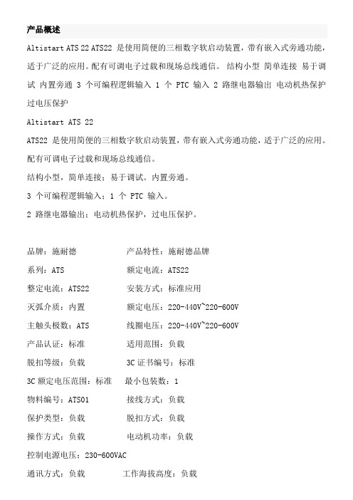
产品概述Altistart ATS 22 ATS22 是使用简便的三相数字软启动装置,带有嵌入式旁通功能,适于广泛的应用。
配有可调电子过载和现场总线通信。
结构小型简单连接易于调试内置旁通 3 个可编程逻辑输入 1 个 PTC 输入 2 路继电器输出电动机热保护过电压保护Altistart ATS 22ATS22 是使用简便的三相数字软启动装置,带有嵌入式旁通功能,适于广泛的应用。
配有可调电子过载和现场总线通信。
结构小型,简单连接;易于调试。
内置旁通。
3 个可编程逻辑输入;1 个 PTC 输入。
2 路继电器输出;电动机热保护,过电压保护。
品牌:施耐德产品特性:施耐德品牌系列:ATS 额定电流:ATS22整定电流:ATS22 安装方式:标准应用灭弧介质:内置额定电压:220-440V~220-600V主触头极数:ATS 线圈电压:220-440V~220-600V产品认证:标准适用范围:负载脱扣等级:负载 3C证书编号:标准3C额定电压范围:标准最小包装数:1物料编号:ATS01 接线方式:负载保护类型:负载脱扣方式:负载操作方式:负载电动机功率:负载控制电源电压:230-600VAC通讯方式:负载工作海拔高度:负载外形尺寸:33*36 机械寿命:9999重量:负载旁路方式:负载每小时起动次数:3333 工作负载系数:9999 壳体防护等级:9999 端子防护等级:9999 额定绝缘电压(Ui):400 起动升压时间:99 斜坡下降时间:S 起动初始电压:400 起动限制电流:AC 工作环境温度:60 备注说明:星三角可售卖地:全国型号:ATS22C17Q 额定电压 220-440V。
Schneider Electric ATS22C25Q软启动器产品说明书
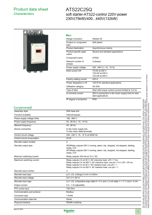
T h e i n f o r m a t i o n p r o v i d e d i n t h i s d o c u m e n t a t i o n c o n t a i n s g e n e r a l d e s c r i p t i o n s a n d /o r t e c h n i c a l c h a r a c t e r i s t i c s o f t h e p e r f o r m a n c e o f t h e p r o d u c t s c o n t a i n e d h e r e i n .T h i s d o c u m e n t a t i o n i s n o t i n t e n d e d a s a s u b s t i t u t e f o r a n d i s n o t t o b e u s e d f o r d e t e r m i n i n g s u i t a b i l i t y o r r e l i a b i l i t y o f t h e s e p r o d u c t s f o r s p e c i f i c u s e r a p p l i c a t i o n s .I t i s t h e d u t y o f a n y s u c h u s e r o r i n t e g r a t o r t o p e r f o r m t h e a p p r o p r i a t e a n d c o m p l e t e r i s k a n a l y s i s , e v a l u a t i o n a n d t e s t i n g o f t h e p r o d u c t s w i t h r e s p e c t t o t h e r e l e v a n t s p e c i f i c a p p l i c a t i o n o r u s e t h e r e o f .N e i t h e r S c h n e i d e r E l e c t r i c I n d u s t r i e s S A S n o r a n y o f i t s a f f i l i a t e s o r s u b s i d i a r i e s s h a l l b e r e s p o n s i b l e o r l i a b l e f o r m i s u s e o f t h e i n f o r m a t i o n c o n t a i n e d h e r e i n .Product data sheetCharacteristicsATS22C25Qsoft starter-ATS22-control 220V-power230V(75kW)/400...440V(132kW)MainRange of product Altistart 22Product or component typeSoft starterProduct destination Asynchronous motorsProduct specific appli-cationSevere and standard applications Component name ATS22Network number of phases3 phasesPower supply voltage 230...440 V (- 15...10 %)Motor power kW75 kW at 230 V 132 kW at 440 V 132 kW at 400 V Factory setting current 233 APower dissipation in W 129 W for standard applications Utilisation category AC-53AType of start Start with torque control (current limited to 3.5 In)Icl nominal current 250 A (connection in the motor supply line) for stan-dard applications IP degree of protectionIP00ComplementaryAssembly style With heat sink Function available Internal bypass Power supply voltage limits 195...484 VPower supply frequency 50...60 Hz (- 10...10 %)Network frequency 45...66 HzDevice connection In the motor supply lineTo the motor delta terminals Control circuit voltage 220...230 V -15...10 % at 50/60 Hz Control circuit consumption 20 W Discrete output number 2Discrete output type(R2)Relay outputs 230 V running, alarm, trip, stopped, not stopped, starting,ready, C/O(R1)Relay outputs 230 V running, alarm, trip, stopped, not stopped, starting,ready, C/OMinimum switching current Relay outputs 100 mA at 12 V, DCMaximum switching currentRelay outputs 2 A at 30 V, DC inductive load, L/R = 7 msRelay outputs 2 A at 250 V, AC inductive load, cos phi = 0.4, L/R = 20 ms Relay outputs 5 A at 30 V, DC resistive load, cos phi = 1Relay outputs 5 A at 250 V, AC resistive load, cos phi = 1Discrete input number 3Discrete input type (LI1, LI2, LI3)logic 5 mA 4.3 kOhm Discrete input voltage 24 V (<= 30 V)Discrete input logic (LI1, LI2, LI3)positive logic state 0 < 5 V and < 2 mA state 1 > 11 V and > 5 mA Output current 0.4...1 Icl adjustable PTC probe input750 Ohm Communication port protocol Modbus Connector type1 RJ45Communication data link SerialPhysical interfaceRS485 multidropTransmission rate4800, 9600 or 19200 bpsMax nodes number31Protection type Thermal protection on starterThermal protection on motorPhase failure on lineMarking CEType of cooling Forced convectionOperating position Vertical +/- 10 degreeHeight425 mmWidth206 mmDepth299 mmProduct weight33 kgEnvironmentElectromagnetic compatibility Voltage/Current impulse conforming to IEC 61000-4-5 level 3Immunity to radiated radio-electrical interference conforming to IEC 61000-4-3level 3Immunity to electrical transients conforming to IEC 61000-4-4 level 4Electrostatic discharge conforming to IEC 61000-4-2 level 3Damped oscillating waves conforming to IEC 61000-4-12 level 3Conducted and radiated emissions conforming to IEC 60947-4-2 level A Standards EN/IEC 60947-4-2Product certifications CCCCSAC-TickGOSTULVibration resistance 1.5 mm (f = 2...13 Hz) conforming to EN/IEC 60068-2-61 gn (f = 13...200 Hz) conforming to EN/IEC 60068-2-6Shock resistance15 gn for 11 ms conforming to EN/IEC 60068-2-27Noise level56 dBPollution degree Level 2 conforming to IEC 60664-1Relative humidity<= 95 % without condensation or dripping water conforming to EN/IEC 60068-2-3 Ambient air temperature for operation> 40...< 60 °C with current derating 2.2 % per °C-10...40 °C without deratingAmbient air temperature for storage-25...70 °COperating altitude> 1000...< 2000 m with current derating of 2.2 % per additional 100 m<= 1000 m without deratingOffer SustainabilitySustainable offer status Not Green Premium productRoHS Compliant - since 0939 -Schneider Electric declaration of conformity Product environmental profile Available Download Product EnvironmentalProduct end of life instructions Available Download End Of Life ManualDimensions DrawingsFrame Size D DimensionsMounting and ClearancePrecautionsStandardsThe Altistart 22 soft starter is compliant with pollution Degree 2 as defined in NEMA ICS1-1 or IEC 60664-1.DANGERAir CirculationLeave sufficient free space to help the air required for cooling purposes to circulate from the bottom to the top of the unit.OverheatingTo avoid the soft starter to overheat, respect the following recommendations:●Mount the Altistart 22 Soft Starter within ± 10° of vertical.●Do not locate the Altistart 22 Soft Starter near heat radiating elements.●Electrical current through the Altistart 22 Soft Starter will result in heat losses that must be dissipated into the ambient air immediatelysurrounding the soft starter. To help prevent a thermal fault, provide sufficient enclosure cooling and/or ventilation to limit the ambient temperature around the soft starter.●If several soft starters are installed in a control panel, arrange them in a row. Do not stack soft starters. Heat generated from the bottomsoft starter can adversely affect the ambient temperature around the top soft starter.Wall mounted or Floor-standing Enclosure with IP 23 Degree of protectionIntroductionTo help proper air circulation in the soft starter, grilles and forced ventilation can be installed.Ventilation GrillesForced Ventilation UnitProduct data sheetConnections and SchemaATS22C25QPower TerminalBar StylePower supply and output to motor Barb 30 mm (1.18 in)a5 mm (0.2 in)BoltM12 (0.47 in)Cable and protective cover Size 2X150 mm²Gauge2X250 MCM Protective cover LA9F703Tightening torque 57 N.m498.75 lb.inPower connections, minimum required wiring section230 Vac control, logic Inputs (LI) 24 Vdc, 3-wire control With Line Contactor, Freewheel or Controlled Stop230 Vac control, logic Inputs (LI) 24 Vdc, 2-wire control,freewheel stopConnection in the motor delta winding in series with each windingWiringATS22 soft starters connected to motors with the delta connections can be inserted in series in the motor windings.The following wiring requieres particular attention. It is documented in the Altistart 22 Soft start - soft stop unit user manual. Please contact Schneider Electric commercial organisation for further informations.ExampleA 400 V - 110 kW motor with a line current of 195 A (nominal current for the delta connection). The current in each winding is equal to 195/1.5 or 130 A. The rating is determined by selecting the soft starter with a permanent nominal current (ICL) just above this current.Product data sheetPerformance CurvesATS22C25QMotor Thermal Protection - Cold CurvesCurvesA Class 10B Class 20C Class 30Trip time for a Standard Application (Class 10)3.5 ln 32 sTrip time for a Severe Application (Class 20)3.5 ln 63 sTrip time for a Severe Application (Class 30)3.5 ln 95 sMotor Thermal Protection - Warm CurvesCurvesA Class 10B Class 20C Class 30Trip time for a Standard Application (Class 10)3.5 ln 16 sTrip time for a Severe Application (Class 20)3.5 ln 32 sTrip time for a Severe Application (Class 30)3.5 ln 48 s。
Schneider Electric Altistart 22软启动器ATS22-控制器产品数据册说
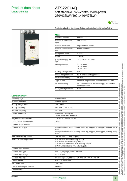
T h e i n f o r m a t i o n p r o v i d e d i n t h i s d o c u m e n t a t i o n c o n t a i n s g e n e r a l d e s c r i p t i o n s a n d /o r t e c h n i c a l c h a r a c t e r i s t i c s o f t h e p e r f o r m a n c e o f t h e p r o d u c t s c o n t a i n e d h e r e i n .T h i s d o c u m e n t a t i o n i s n o t i n t e n d e d a s a s u b s t i t u t e f o r a n d i s n o t t o b e u s e d f o r d e t e r m i n i n g s u i t a b i l i t y o r r e l i a b i l i t y o f t h e s e p r o d u c t s f o r s p e c i f i c u s e r a p p l i c a t i o n s .I t i s t h e d u t y o f a n y s u c h u s e r o r i n t e g r a t o r t o p e r f o r m t h e a p p r o p r i a t e a n d c o m p l e t e r i s k a n a l y s i s , e v a l u a t i o n a n d t e s t i n g o f t h e p r o d u c t s w i t h r e s p e c t t o t h e r e l e v a n t s p e c i f i c a p p l i c a t i o n o r u s e t h e r e o f .N e i t h e r S c h n e i d e r E l e c t r i c I n d u s t r i e s S A S n o r a n y o f i t s a f f i l i a t e s o r s u b s i d i a r i e s s h a l l b e r e s p o n s i b l e o r l i a b l e f o r m i s u s e o f t h e i n f o r m a t i o n c o n t a i n e d h e r e i n .Product data sheetCharacteristicsATS22C14Qsoft starter-ATS22-control 220V-power230V(37kW)/400...440V(75kW)Product availability: Non-Stock - Not normally stocked in distribution facilityMainRange of product Altistart 22Product or component typeSoft starterProduct destination Asynchronous motors Product specific applica-tionPumps and fans Component name ATS22Phase3 phase[Us] rated supply volt-age230...440 V - 15...10 %Motor power kW37 KW 230 V 75 KW 400 V 75 kW 440 V Factory setting current 131 APower dissipation in W 82 W for standard applications Utilisation category AC-53AType of start Start with torque control (current limited to 3.5 In)IcL starter rating 140 A connection in the motor supply line for stan-dard applications IP degree of protectionIP00ComplementaryAssembly style With heat sink Function available Internal bypass Supply voltage limits 195…484 VSupply frequency 50...60 Hz - 10...10 %Network frequency 45...66 HzDevice connection In the motor supply lineTo the motor delta terminals [Uc] control circuit voltage 230 V - 15...10 % 50/60 Hz Control circuit consumption 20 W Discrete output number 2Discrete output typeRelay outputs R1 230 V running, alarm, trip, stopped, not stopped, starting, ready C/ORelay outputs R2 230 V running, alarm, trip, stopped, not stopped, starting, ready C/OMinimum switching current 100 mA 12 V DC relay outputs)Maximum switching current5 A 250 V AC resistive 1 relay outputs 5 A 30 V DC resistive 1 relay outputs2 A 250 V AC inductive 0.4 20 ms relay outputs 2 A 30 V DC inductive 7 ms relay outputs Discrete input number 3Discrete input type LI1, LI2, LI3) logic, 5 mA 4.3 kOhm Discrete input voltage 24 V <= 30 VDiscrete input logic Positive logic LI1, LI2, LI3 < 5 V <= 2 mA > 11 V, >= 5 mA Output current 0.4...1 Icl adjustable PTC probe input750 Ohm Communication port protocol Modbus Connector type1 RJ45Communication data link SerialPhysical interface RS485 multidropTransmission rate4800, 9600 or 19200 bpsInstalled device31Protection type Phase failure lineThermal protection motorThermal protection starterMarking CEType of cooling Forced convectionOperating position Vertical +/- 10 degreeHeight14.02 in (356 mm)Width 5.91 in (150 mm)Depth9.04 in (229.5 mm)Net weight39.68 lb(US) (18 kg)Motor power range AC-330…50 KW 200…240 V 3 phase55…100 kW 380…440 V 3 phaseMotor starter type Soft starterEnvironmentElectromagnetic compatibility Conducted and radiated emissions level A IEC 60947-4-2Damped oscillating waves level 3 IEC 61000-4-12Electrostatic discharge level 3 IEC 61000-4-2Immunity to electrical transients level 4 IEC 61000-4-4Immunity to radiated radio-electrical interference level 3 IEC 61000-4-3Voltage/current impulse level 3 IEC 61000-4-5Standards EN/IEC 60947-4-2Product certifications ULCSAC-TickGOSTCCCVibration resistance 1 gn 13…200 Hz)EN/IEC 60068-2-61.5 mm 2…13 Hz)EN/IEC 60068-2-6Shock resistance15 gn 11 ms EN/IEC 60068-2-27Noise level56 dBPollution degree Level 2 IEC 60664-1Relative humidity0…95 % without condensation or dripping water EN/IEC 60068-2-3Ambient air temperature for operation14…104 °F (-10…40 °C) without)104…140 °F (40…60 °C) with current derating 2.2 % per °C)Ambient air temperature for storage-13…158 °F (-25…70 °C)Operating altitude<= 3280.84 ft (1000 m) without> 3280.84...< 6561.68 ft (> 1000...< 2000 m) with current derating of 2.2 % peradditional 100 mOrdering and shipping detailsCategory22576 - ATS22 ALTISTARTDiscount Schedule CP1GGTIN03606480167256Package weight(Lbs)12.67 kg (27.94 lb(US))Returnability NoCountry of origin IDOffer SustainabilitySustainable offer status Green Premium productREACh Regulation REACh DeclarationEU RoHS Directive Pro-active compliance (Product out of EU RoHS legal scope)EU RoHS Decla-rationMercury free YesRoHS exemption information YesChina RoHS Regulation China RoHS DeclarationEnvironmental Disclosure Product Environmental ProfileCircularity Profile End Of Life InformationWEEE The product must be disposed on European Union markets following specificwaste collection and never end up in rubbish bins.Contractual warrantyWarranty18 monthsDimensions DrawingsFrame Size C DimensionsMounting and ClearancePrecautionsStandardsThe Altistart 22 soft starter is compliant with pollution Degree 2 as defined in NEMA ICS1-1 or IEC 60664-1.DANGERAir CirculationLeave sufficient free space to help the air required for cooling purposes to circulate from the bottom to the top of the unit.OverheatingTo avoid the soft starter to overheat, respect the following recommendations:●Mount the Altistart 22 Soft Starter within ± 10° of vertical.●Do not locate the Altistart 22 Soft Starter near heat radiating elements.●Electrical current through the Altistart 22 Soft Starter will result in heat losses that must be dissipated into the ambient air immediatelysurrounding the soft starter. To help prevent a thermal fault, provide sufficient enclosure cooling and/or ventilation to limit the ambient temperature around the soft starter.●If several soft starters are installed in a control panel, arrange them in a row. Do not stack soft starters. Heat generated from the bottomsoft starter can adversely affect the ambient temperature around the top soft starter.MountingConnection Between the Fan and the Altistart 22 Soft Starter1Altistart 22 Soft Starter2FanWall mounted or Floor-standing Enclosure with IP 23 Degree of protectionIntroductionTo help proper air circulation in the soft starter, grilles and forced ventilation can be installed. Ventilation GrillesForced Ventilation UnitProduct data sheetATS22C14QConnections and SchemaPower TerminalBar StylePower supply and output to motor Bar b20 mm (0.79 in) a 5 mm (0.2 in)Bolt M8 (0.31 in)Cable and protective cover Size95 mm²Gauge250 MCMProtective cover LA9F702Tightening torque18 N.m157.5 lb.inPower connections, minimum required wiring section230 Vac control, logic Inputs (LI) 24 Vdc, 3-wire controlWith Line Contactor, Freewheel or Controlled Stop230 Vac control, logic Inputs (LI) 24 Vdc, 2-wire control,freewheel stopConnection in the motor delta winding in series with each windingWiringATS22 soft starters connected to motors with the delta connections can be inserted in series in the motor windings.The following wiring requieres particular attention. It is documented in the Altistart 22 Soft start - soft stop unit user manual. Please contact Schneider Electric commercial organisation for further informations.ExampleA 400 V - 110 kW motor with a line current of 195 A (nominal current for the delta connection). The current in each winding is equal to 195/1.5 or 130 A. The rating is determined by selecting the soft starter with a permanent nominal current (ICL) just above this current.Product data sheetATS22C14Q Performance CurvesMotor Thermal Protection - Cold CurvesCurvesA Class 10B Class 20C Class 30Trip time for a Standard Application (Class 10)3.5 ln32 sTrip time for a Severe Application (Class 20)3.5 ln63 sTrip time for a Severe Application (Class 30)3.5 ln95 sMotor Thermal Protection - Warm Curves CurvesA Class 10B Class 20C Class 30Trip time for a Standard Application (Class 10) 3.5 ln16 sTrip time for a Severe Application (Class 20) 3.5 ln32 sTrip time for a Severe Application (Class 30) 3.5 ln48 s。
ats22参数手册

ats22参数手册一、简介ATS22是一款广泛应用于电机控制的智能型可编程软启动器。
本手册将详细介绍ATS22的参数设置和使用方法,以帮助用户正确配置和操作该设备,并实现对电机的高效控制。
二、ATS22参数概述1. 电源参数设置- 电源类型:单相或三相- 额定电压和频率:根据实际需求设置2. 电机参数设置- 额定电流:根据电机的额定电流设置- 额定功率或负载系数:根据负载情况设置3. 控制参数设置- 启动方式:直接启动、定时启动或外部信号启动- 加速时间和减速时间:根据需要平衡启动速度和设备寿命- 过载保护:设置过载保护参数以防止电机过载损坏- 电流限制:根据实际需求设置,限制电机运行时的最大电流- 刹车控制:设置刹车延迟和刹车过程的控制参数4. 通信参数设置- 通信协议:选择合适的通信协议以便与其他设备进行信息交换 - 通信地址:设置ATS22在通信网络中的地址5. 高级参数设置- 错误管理:选择错误处理方式和显示方式- 时间管理:设置时钟、定时器等时间相关参数- 节能功能:启用节能功能以减少能源消耗- 其他特殊功能:依据实际需求设置其他特殊功能参数三、ATS22参数配置步骤1. 开始配置首先,确保ATS22与电源和电机正确连接,并处于待机状态。
2. 进入参数配置界面通过按下菜单键或触摸屏上的相应按钮,进入ATS22的参数配置界面。
3. 设置电源参数根据实际情况,选择单相或三相电源类型,并设置额定电压和频率。
4. 设置电机参数根据电机的额定电流和负载情况,设置相应的参数。
5. 设置控制参数根据启动方式、加速时间、减速时间、过载保护等需求,调整参数设置。
6. 设置通信参数如果需要与其他设备进行通信,选择相应的通信协议并设置通信地址。
7. 设置高级参数根据需求选择错误管理方式、时间管理设置、节能功能等高级参数。
8. 参数保存与生效在设置完毕后,将参数保存并使其生效,ATS22将按照配置参数进行电机控制。
施耐德ATS22软启动器使用说明
施耐德ATS22软启动器使用说明施耐德ATS22软启动器是一种高科技的电器,是用来控制电机启动和运转的,具有防止过载、电压不稳定、欠电压等问题的功能,可保护电器的安全,延长其使用寿命。
第一步:初始设置在安装ATS22软启动器之前,需要先做一些设置以确保电器的正常运行。
首先需要确保电器的安装位置水平稳定,然后按照说明书的步骤连接电源和电机。
接着,需要进行ATS22的初始设置。
首先需要设置行程量(FLC、FLC从0到100,在小于FLC时电流会逐渐增大)以及预警保护等级(有1~6级可选,级别越高保护越强)等。
第二步:启动启动ATS22软启动器之后,需要进行一些电机的监测和运行。
首先需要检查电机的运转情况,确保电机运转平稳、电流不超过额定电流、电压不超过额定电压等。
如果出现问题,需要及时关机进行维修或调试。
同时,需要注意对电器的保护。
ATS22软启动器有多种功能,例如内部保护、控制和监控等。
需要保持电器处于最佳状态,避免电路短路、损坏等情况的发生。
第三步:调试和维护调试和维护是ATS22软启动器的重要工作,可确保电器始终处于良好状态。
调试可根据不同电机的特性选择不同启动方式,以达到最佳的效果,例如定扭矩加速、恒扭矩加速、恒力矩启动等。
同时,还需要对电器进行维护。
例如定期检查电路的状态,清洁连接部位,检查电机连接情况等。
保持电器的清洁干燥,确保电路线路无故障,可延长电器的使用寿命。
总结施耐德ATS22软启动器是一款功能强大、安全可靠的电器。
在使用过程中,需要注意初次设置、启动、调试和维护等过程。
通过这些步骤,可以确保电器始终处于最佳状态,为产线的运行提供有力的保障。
ATS22施耐德软启动操作规程
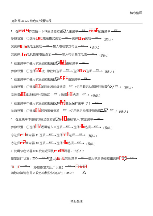
精心整理
精心整理 施耐德ATS22软启动设置流程
1
.在
−
−→
−出现配置菜单−−→−
ENT 参数设置:①选择高级模式选项−−→−
ENT
选择选项
−−→−ENT (确认) ②选择
线电压选项−−→−ENT 输入电机额定电压−−→−ENT (确认) ③选择电机额定电压选项−−→−ENT 输入电机额定电流−−→−ENT (确认)
2.ENT 参数设置:①选择起-停控制选项−−→−ENT 选项
3.参数设置:①选择
加速斜坡时间选项−−→−ENT ②选择减速斜坡时间选项−−→−ENT 选择
4.参数设置:①选择
5.在主菜单中使用软启动器按钮选择高级输入/输出菜单−−→−ENT
参数设置:①选择
逻辑输入选项−−→−ENT (确认) ②选择
选择选项−−→−ENT (确认) ③选择选择选项−−→−ENT
(确认) 6.界面。
试机!!! 恢复出厂设置:ESC+−−ENT 实用菜单−−→−ENT 使用软启动器按钮选择
−−→−ENT −−→−ENT (参数恢复为出厂设置)−
−→−ENT 清除故障消息并对软启动复位快捷按钮:ENT++。
施耐德ats22软启动器

5
6
7
8
9
10
型号: 12页
88
组合: 16页
ATS 22 软起动-软停止单元
介绍
ATS 22软起动-软停止单元通过电压和转矩, 对额定功率在4至400 kW范围内的三相鼠 笼式异步电机进行受控起动和停机。
它的出厂设置适用于采用10级电机保护等级的标准应用。
ATS 22软起动-软停止单元的设计旨在满足十分重视鲁棒性、人员和设备安全性以及 调试便捷性的应用场合的性能要求。
符合标准
类型 传导式和辐射式 EMC 散射性 抗振性
抗冲击性
符合IEC 60947-4-2 符合IEC 60068-2-6 符合IEC 60068-2-27
性能 A级
2 至 13 Hz为1.5 mm, 13 至 200 Hz为1 gn 15 gn 持续 11 ms
最高环境污染等级
符合IEC 60664-1
7
8
9
10
99
介绍 (续)
ATS 22 软起动-软停止单元
1
产品
ATS 22 软起动-软停止单元产品用于功率范围在4至400 kW的电机,包含 2 个电压
系列:
b 230 V至440 V、50/60 Hz的三相电源电压 (ATS 22pppQ)
b 208 V至600 V、50/60 Hz的三相电源电压 (ATS 22pppS6和ATS 22pppS6U)
ATS 01N2pppp
请参见“软起动器和变频器”产品目录。
简单和复杂机械的受控起动和停止
4...400
– – – 4...400 – – 4...355 –
3 可配置的电压斜坡 标准
内置 1个PTC传感器输入 3 – – 2 (“常开”/“常闭”)
Schneider Electric Altistart 22快速启动指南说明书

Quick start guide - Altistart 22Preliminary informationInformation below is designed to use for simple applications with 2-wire control mode and freewheel stop.If you need more information, or for other applications, see the User manual (BBV51330) on . For a hard copy, contact your local sales Office or Schneider Electric representative.Note:DO NOT USE this guide for Altistart 22 connected inside the delta of the motor (it means Altistart 22 connected to the motor with delta connections in series with each motor windings). In this case, see User manual on .Read and understand these instructions before performing any procedure with this soft starter.Electrical equipment should be installed, operated, serviced and maintained only by qualified personnel. No responsibility is assumed by SchneiderElectric for any consequences out of the use of this material.Check the delivery of the soft starterRemove Altistart 22 from the packaging and check that it has not been damaged.Ensure that the soft starter reference on the nameplate is similar to the purchase order delivery note.Write the soft starter model Reference: ATS22 ______and Serial Number :___________________Check the line voltage compatibilityCheck that the line voltage is compatible with the supply range of the soft starter. Line voltage __________ Volts Soft starter voltage range ______________ Volts Control voltage _______ Volts Soft starter control voltage range _______ VoltsMount the soft starter verticallyFor a surrounding air temperature up to 40 °C (104°F).For other thermal conditions, see user manual (BBV51330) on .WARNINGDAMAGED SOFT STARTER EQUIPMENTDo not operate or install any soft starter or soft starter accessory that appears damaged.Failure to follow these instructions can result in death, serious injury, or equipment dam-age.S1A1038804Connect the soft starter-Check that the control supplyis 230V for CL1 and CL2.-Remove the red sticker which covers the CL1-CL2 terminals.-Wire control supply: CL1 and CL2.-Wire logical inputs: LI1 and LI2.(1) Check the operating limits of the contact.(2) Select a voltage transformer in accordancewith the mains voltage.Note: For additional information in order to size the protective and control devices, refer to the catalog or the user manual available on Connect the soft starter-Check that the control supplyis 110V for CL1 and CL2.-Remove the red sticker which covers the CL1-CL2 terminals.-Wire control supply: CL1 and CL2.-Wire logical inputs: LI1 and LI2.-Wire the relay: R2A and R2C.(1) Check the operating limits of the contact.(2) Select a voltage transformer in accordance withthe mains voltage.Note: For additional information in order to size the protective and control devices, refer to the catalog or the user manual available on Apply power to the Altistart 22 and start the motor•Close the enclosure.•PushS2button.•The soft starter displays rdY.•Close S3, the motor starts.Factory settingsThe Altistart 22 is factory configured for most standard applications. If the factory configuration is not suitable for your application, refer to User manual (BBV51330) on . Here is the list of writable parameters in an “easy start up” mode.rdY: soft starter ready, when power and control voltage are present and the motor is not operating.nrdY: when power is not supplied and control voltage is supplied or when power and control voltage are present with LI1 not connected and LI2 present (run command).conFConfigurationICL Soft starter rated current According to the soft starter ratingdLtA Connection type (Line or delta)LInEUIn Line voltage ATS22ppp Q range:400 VacATS22ppp S6-S6U ranges:480 VacIn Motor rated current According to the soft starter ratingCod Setting lock nLoC (Not locked)LAC Advanced mode oFFSEtAdjustmentst90Initial voltage 30% of input voltageILt Current limit 350% of IntLSMax start time IS sACC Acceleration timeID sdEC Deceleration time FrEE (Freewheel)EdC Final torque OtHP Motor thermal protection IO(IEC class 10)Power on the control•Check that S3 is open.•Switch on: Q1, Q2, Q3 and Q4.•The soft starter displays nrdY.Adjust UIn line voltage•Push scroll down button to reach conF menu.•Pushbutton.•Push scroll down button to reach UIn parameter.•Set UIn to the main line voltage ac value, usingscroll Up/down.•Push button to validate the UIn value.Adjust In motor rated current•In conF menu•Push scroll down button to reach In parameter.•See Nominal Motor Current on Motor Nameplate(Motor Full Load Amps) in STAR connection, note the “Amps” value.•Set In to this value using scroll Up/down.•Push button to validate the In value.。
ATS22 软启说明书

ATS22
软起动 - 软停止单元
用户手册
目录
重要信息 ___________________________________________________________________________________________________________________ 4 开始之前 ___________________________________________________________________________________________________________________ 5 文档结构 ___________________________________________________________________________________________________________________ 6
危险
危险表示极可能存在危险,如果不遵守说明,可能将导致严重的人身伤害甚至死亡。
警告
警告表示可能存在危险,如果不遵守说明,可导致设备损坏、严重的人身伤害甚至死亡。
小心
小心表示可能存在危险,如果不遵守说明,可导致设备损坏或严重的人身伤害。
小心
小心不带有安全警示符号的小心标识,表示可能存在危险,如果不遵守说明,可导致设备损失。 请注意
软起动器设置步骤 ( 另参见 “快速起动”指南 ) ____________________________________________________________________ 7
接收和搬运 ______________________________________________________________________________
ATS22快速入门

检查线电压
检查线电压是否与软起动器的电压范围一致。
线电压 __________ V 软起动器电压范围 ______________ V
控制电压 _______ V 软起动器控制电压范围 _______ V
安装软起动器垂直
用于气温低于或等于 40 °C 的环境。
危险
电击、爆炸和电弧危险
ATS22 软件起动器是开敞设备,必须安装在合适的机柜中。
基本信息
S1A1039303
以下信息用于使用 2 线控制模式和自由停车的简单应用。 如果您需要更多信息或要了解其它应用,请参阅 上的 《用户手册 (SCDOC1379)》。如需打印件,请与您当地的销售 公司或 Schneider Electric 代表联系。
注:有关如何确定保护和控制设备规模的更多信息,请参阅 上的目录或 《用户手册》
3/4
S1A10393 - 07/2012
控制电路上电
• 检查 S3 是否打开。
• 接通:Q1、 Q2、 Q3 和 Q4。 • 软起动器显示 nrdY。
- 断开所有电源,包括可能会带电的外部控制电源。 - 在所有电源分断装置上放置 “禁止合闸” 标签。 - 将所有电源分断装置锁定在打开位置。 • 上电前应先盖上机盖。
若不按照说明操作,则可能会导致严重的人身伤亡。
电气设备的安装、操作、维修和维护工作仅限于合格人员执行。对于使用本资料所引发的任何后果, Schneider Electric 概不负责。
客户设置
4/4
S1A10393 - 07/2012
Motor
M1 3
(1) 检查触点的操作限制。 (2) 根据电源电压选择变压器。
b) 连接控制:
ATS22施耐德软启动操作流程
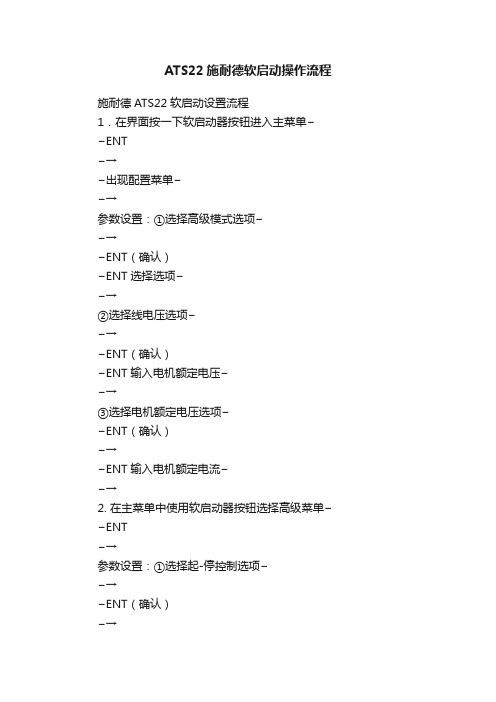
ATS22施耐德软启动操作流程施耐德ATS22软启动设置流程1.在界面按一下软启动器按钮进入主菜单−−ENT−→−出现配置菜单−−→参数设置:①选择高级模式选项−−→−ENT(确认)−ENT选择选项−−→②选择线电压选项−−→−ENT(确认)−ENT输入电机额定电压−−→③选择电机额定电压选项−−ENT(确认)−→−ENT输入电机额定电流−−→2. 在主菜单中使用软启动器按钮选择高级菜单−−ENT−→参数设置:①选择起-停控制选项−−→−ENT(确认)−→−ENT选择选项−3. 在主菜单中使用软启动器设定菜单−−ENT−→参数设置:①选择加速斜坡时间选项−−ENT(确认)−→−→−ENT使用软启动器按钮选择10−②选择减速斜坡时间选项−−ENT(确认)−→−ENT选择选项−−→4. 按钮选择高级保护菜单(1)−−ENT−→参数设置:①选择过流阀值选项−−ENT(确认)−→−→−ENT使用软启动器按钮选择130−5.在主菜单中使用软启动器按钮选择高级输入/输出菜单−−ENT−→参数设置:①选择逻辑输入2选项−−→−ENT(确认)−ENT选择选项−−→②选择继电器R1选项−−→−ENT(确认)−ENT选择选项−−→③选择继电器R2选项−−→−ENT(确认)−ENT选择选项−−→6.使用软启动器ESC按钮返回到界面。
试机恢复出厂设置:ESC + −−→−ENT按钮选择−−ENT−ENT进入实用菜单−−→−→−→−ENT−→−ENT(参数恢复为出厂设置)−−清除故障消息并对软启动复位快捷按钮: ENT + +。
- 1、下载文档前请自行甄别文档内容的完整性,平台不提供额外的编辑、内容补充、找答案等附加服务。
- 2、"仅部分预览"的文档,不可在线预览部分如存在完整性等问题,可反馈申请退款(可完整预览的文档不适用该条件!)。
- 3、如文档侵犯您的权益,请联系客服反馈,我们会尽快为您处理(人工客服工作时间:9:00-18:30)。
ATS22
软起动 - 软停止单元
用户手册
目录
重要信息 ___________________________________________________________________________________________________________________ 4 开始之前 _________________________________ቤተ መጻሕፍቲ ባይዱ_________________________________________________________________________________ 5 文档结构 ___________________________________________________________________________________________________________________ 6
• 用户有责任遵守国际和国内有关所有设备接地事项的电气规范要求。
3
重要信息
注意
在安装、操作或维护本设备之前,请仔细阅读这些说明,并熟悉本设备。在本手册中或设备上可能会出现下列特殊信息,以告诫潜在的危险 或提醒您注意某些被阐明或简化了的信息。
“危险”或 “警告”标签上附加的本符号表示存在电击危险,如果使用者不遵照使用说明进行操作,会造成人身伤害。
这是提醒注意安全的符号。用于提醒使用者可能存在造成人身伤害的安全隐患。请务必遵循此标志附注的所有安全须知进行 操作,以免造成人员伤亡。
电气设备只能由专业人员进行安装、操作、维修和维护。施耐德电气对于不遵循本说明而引发的任何后果概不负责。 © 2009 Schneider Electric. 版权所有。
4
开始之前
在对本软起动器进行任何操作之前,请阅读并理解下列说明。
危险
电击、爆炸或闪弧危险
• 在安装或操作 ATS 22 之前,请先阅读并理解本手册。只有专业人员才能对此软起动器进行安装、调试、修理与维护。
危险
危险表示极可能存在危险,如果不遵守说明,可能将导致严重的人身伤害甚至死亡。
警告
警告表示可能存在危险,如果不遵守说明,可导致设备损坏、严重的人身伤害甚至死亡。
小心
小心表示可能存在危险,如果不遵守说明,可导致设备损坏或严重的人身伤害。
小心
小心不带有安全警示符号的小心标识,表示可能存在危险,如果不遵守说明,可导致设备损失。 请注意
软起动器设置步骤 ( 另参见 “快速起动”指南 ) ____________________________________________________________________ 7
接收和搬运 _________________________________________________________________________________________________________________ 8 选型_______________________________________________________________________________________________________________________ 10 尺寸和重量 _________________________________________________________________________________________________________________ 14 安装________________________________________________________________________________________________________________________ 17 安装 - 风扇选件 _____________________________________________________________________________________________________________ 20 热保护 ____________________________________________________________________________________________________________________ 22 连线_______________________________________________________________________________________________________________________ 26 连线 - 动力端子 _____________________________________________________________________________________________________________ 32 连线 - 控制端子 _____________________________________________________________________________________________________________ 35 连线 - 标准连接 - 应用图 _____________________________________________________________________________________________________ 38 显示终端 __________________________________________________________________________________________________________________ 42 远程显示终端 - 选件_________________________________________________________________________________________________________ 44 编程_______________________________________________________________________________________________________________________ 45 参数列表 __________________________________________________________________________________________________________________ 48 参数设置 __________________________________________________________________________________________________________________ 49 配置菜单 (ConF) ___________________________________________________________________________________________________________ 50 设定菜单 (SEt) ______________________________________________________________________________________________________________ 51 高级调整菜单 (AdJ)_________________________________________________________________________________________________________ 53 高级设定菜单 (SEt2) ________________________________________________________________________________________________________ 55 高级保护菜单 (PrO)_________________________________________________________________________________________________________ 56 高级输入 / 输出菜单 (IO) ____________________________________________________________________________________________________ 60 高级通讯菜单 (COP) ________________________________________________________________________________________________________ 62 高级监视菜单 (SUP) ________________________________________________________________________________________________________ 63 实用菜单 (UtIL)_____________________________________________________________________________________________________________ 64 命令通道 __________________________________________________________________________________________________________________ 65 Modbus 功能 _______________________________________________________________________________________________________________ 68 与 RS485 总线的连接 _______________________________________________________________________________________________________ 73 维护_______________________________________________________________________________________________________________________ 74 诊断 / 故障排查 ____________________________________________________________________________________________________________ 75 参数索引和 Modbus 通讯地址________________________________________________________________________________________________ 77 附录 1:UL508 图解 ________________________________________________________________________________________________________ 82 附录 2:短路额定值和支路保护 ______________________________________________________________________________________________ 84
