Agilent-眼图、抖动、相噪
Agilent仪器维护及故障诊断

(隔垫)吹扫出口 分流出口 放空阀
色谱柱
色谱柱
Agilent 6890 /7890 GC 分流/无分流进样口
- 进样方式与进样过程
3. 样品与载气的混合
4. 衬管过载
总流量
(隔垫)吹扫出口
总流量
(隔垫)吹扫出口
= 载气 = 样品分子 = 溶剂分子
分流出口
放空阀
为了保证分流比的概念真实有效, 样品(溶剂+被分析物)必须与载 气充分混合,形成一个均匀的混合 物。
2,检查气体流量设置,FID一般H2流量35-40ml/min,空气为350-400ml/min FPD H2流量75ml/min,空气为100ml/min。
3,检查柱子流量是否过大,工作站上载气类型、柱子配置是否正确,柱子流速过大会吹灭火焰。
4,观察尾吹气流量(Makeup Flow)设置,FID一般尾吹气流量和注流量之和大致等于30-35ml/min FPD尾吹气流量为60ml/min 尾. 吹气流量过大会吹灭火焰。
34ml
3.0ml 30ml
4.0ml
3.0ml 0ml
31ml
1.0ml
1.0ml
1.0ml
11
Agilent Βιβλιοθήκη 890 /7890 GC 分流/无分流进样口
- 进样方式与进样过程
1. 进样
总流量
(隔垫)吹扫出口
分流出口
放空阀 = 载气 = 液态样品分子
2. 样品气化
总流量
= 载气 = 样品分子 = 溶剂分子
Frit Valve
FS
? mL/min
Valve
Frit PS
PS
Split Vent Trap
jitter抖动(相位噪声)的概念及其测量方法(EyeDiagram)
抖动的概念及其测量方法摘要:在数字通信系统,特别是同步系统中,随着系统时钟频率的不断提高,时间抖动成为影响通信质量的关键因素。
本文介绍了时间抖动(jitter)的概念及其分析方法。
关键字:时间抖动、jitter、相位噪声、测量一、引言随着通信系统中的时钟速率迈入GHz级,抖动这个在模拟设计中十分关键的因素,也开始在数字设计领域中日益得到人们的重视。
在高速系统中,时钟或振荡器波形的时序误差会限制一个数字I/O接口的最大速率。
不仅如此,它还会导致通信链路的误码率增大,甚至限制A/D转换器的动态范围。
有资料表明在3GHz 以上的系统中,时间抖动(jitter)会导致码间干扰(ISI),造成传输误码率上升。
在此趋势下,高速数字设备的设计师们也开始更多地关注时序因素。
本文向数字设计师们介绍了抖动的基本概念,分析了它对系统性能的影响,并给出了能够将相位抖动降至最低的常用电路技术。
二、时间抖动的概念在理想情况下,一个频率固定的完美的脉冲信号(以1MHz为例)的持续时间应该恰好是1us,每500ns有一个跳变沿。
但不幸的是,这种信号并不存在。
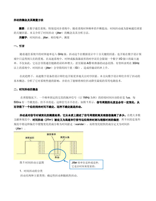
如图1所示,信号周期的长度总会有一定变化,从而导致下一个沿的到来时间不确定。
这种不确定就是抖动。
抖动是对信号时域变化的测量结果,它从本质上描述了信号周期距离其理想值偏离了多少。
在绝大多数文献和规范中,时间抖动(jitter)被定义为高速串行信号边沿到来时刻与理想时刻的偏差,所不同的是某些规范中将这种偏差中缓慢变化的成分称为时间游走(wander),而将变化较快的成分定义为时间抖(jitter)。
图1 时间抖动示意图1.时间抖动的分类抖动有两种主要类型:确定性抖动和随机性抖动。
确定性抖动是由可识别的干扰信号造成的,这种抖动通常幅度有限,具备特定的(而非随机的)产生原因,而且不能进行统计分析。
随机抖动是指由较难预测的因素导致的时序变化。
例如,能够影响半导体晶体材料迁移率的温度因素,就可能造成载子流的随机变化。
AgilentEA仪器操作作业指导书
工艺文件产品型号:ZXC10 BTSB部件代号:BTS文件名称: Agilent E4406A仪器操作作业指导书文件编号:版本:A共 29 页(包括封面)拟制审核会签标准化批准中兴通讯股份有限公司1适用范围用于指导如何使用Agilent E4406A型(或者Agilent E4445A型)矢量信号分析仪测试ZXC10 BTSB(包括ZXC10 BTSB I1系统、ZXC10 BTSB I2系统)和ZXC10 BTSAE系统的无线指标。
2工具大功率衰减器(40dB衰减,50Ω,工作频段应满足CDMA450MHz ~频段) 1个Agilent E4406A型矢量信号分析仪(或者Agilent E4445A型)1台后台服务器(安装了ZXC10 OMC后台软件) 1台时钟电缆(BNC阳-SMB阴) 2根射频电缆(N阳-N阳,2米) 1根射频电缆(N阳-N阳,1米) 1根集线器 1个地线1根3测试方法和步骤在ZXC10 BTSB系统调试和射频的有关单板调试中,需要对系统或单板的无线指标进行测量,无线指标是否达标是衡量系统或单板是否合格的一个重要标准。
在调试中,我们采用Agilent E4406A型矢量信号分析仪对系统或单板的无线指标进行测量。
具体测试项目测试方法请按后面的说明进行操作。
3.1仪器上电前的准备工作接地:矢量信号分析仪为贵重仪器,在仪器上电之前应该保证仪器有良好的接地,以免对仪器造成不必要的损害。
在仪器的后背板的右下角有一个接地的环形接线柱,用接地电缆把仪器接地接线柱和大地良好连接起来。
外接时钟参考源:矢量信号分析仪需要外部提供PP2S和10M的参考时钟。
对于ZXC10 BTSB I1 、ZXC10 BTSB I2机架,在GCM单板的前面板上有PP2S时钟和10M时钟的输出口。
用两根时钟电缆(BNC阳-SMB阴)分别连接仪器后背板的接线柱和基站的主用GCM单板上的时钟参考源的输出口。
具体为:TRIGGER IN接线柱接ZXC10 BTSB 机架的主用GCM面板的PP2S输出口,EXT REF IN接线柱连接主用GCM面板的10M输出口。
高速数字信号的眼图和抖动测量
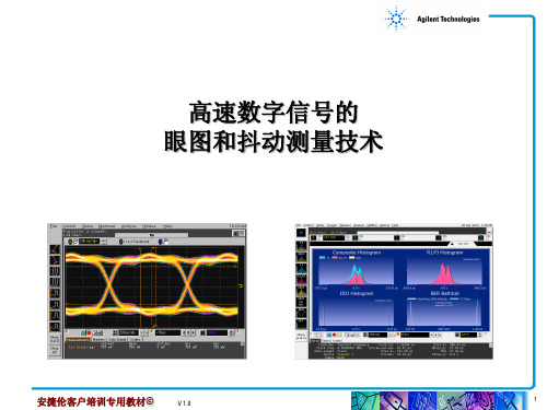
Total Jitter (TJ)
Data-Uncorrelated
Deterministic Jitter (DJ) Periodic Jitter (PJ) Sub Rate Jitter (SRJ)
Random Jitter (RJ)
Data Dependent Jitter (DDJ) Inter-symbol Interference (ISI)
高速数字信号的 眼图和抖动测量技术
安捷伦客户培训专用教材©
V 1.0
1
数字信号的眼图
• 数字信号的眼图包含丰富的信息,体现数字信号的整体特征,能够很好的 评估数字信号的品质,因而数字信号眼图分析是数字系统信号完整性分析 的关键之一。 • 眼图实际上是一系列数字信号的不同码型按一定的规律在示波器屏幕上累 积显示的结果。
• PLL(锁相环路)
• 模拟链路接收端通过硬件PLL恢复时钟后看到的抖动成分
• 外时钟恢复
• 被测信号没有使用嵌入式时钟而是具有显性时钟信号
• 特殊方式
• 实例:PCI Express时钟恢复方式
安捷伦客户培训专用教材©
V 1.0
17
PLL带宽对抖动测量的影响
抖动传递函数JTF:恢复时钟中的抖动与输入信号中抖动之比
V 1.0
14
Bathtub曲线
• Bathtub曲线的中部大部分地 受到Rj的影响 • 靠向眼睛交叉点较大地受到Dj 影响 • 在既定的BER水平下,Dj的PkPk值与Rj的标准偏差值影响眼 睛的张开度
安捷伦客户培训专用教材©
V 1.0
15
为什么需要时钟恢复
数字信号的很多测试测量都需要时钟信息
Agilent GC基线噪音与色谱柱老化
c根据GC ,GCMSD 的故障统计,90%的问题发生在进样口。
由于进样口引起的不良现象大体有:重复性差、出现鬼峰、峰型差、进样歧视、基线出现不规律毛刺等。
这些现象与进样口的几种消耗品部件有关:1,进样隔垫:隔垫的作用隔垫将样品流路与外部隔开,进样针插入时,能保持系统内压,防止泄漏,避免外部空气渗入,污染系统。
隔垫一般由耐高温,惰性好,气密性好的硅橡胶制成。
为什么要更换隔垫隔垫要定期更换,为防止:•漏汽,分解,样品损失,出鬼峰,柱效下降如何避免出现问题•进样口温度不要超过隔垫的最高使用温度•定期更换(200次)•安装后用“手紧“•使用针尖锋利的注射器2,衬管和分流平板;污染的衬管样品分解或歧视,c污染的分流平板新的分流平板新的衬管c 衬管和分流平板可以清洗,可以用无机酸或者有机溶剂超声、清洗,但不能刷洗。
衬管清洗后应当进行硅烷化处理,衬管里的玻璃棉也应该是硅烷化处理过的。
Agilent 有可订货的去活玻璃棉。
衬管有多种,要选择合适的类型,以下是几种常用的衬管类型:去活性低压降,870uL ,分流,部件号5183-4647广泛适用,870uL ,分流/不分流,部件号5183-4711去活性,900uL ,不分流,部件号5062-3587去活性,800uL ,不分流,部件号5181-33154mm ID,玻璃毛,990uL ,分流,部件号19251-60540去活玻璃棉50g/包装部件号:5080-8764农残专用玻璃棉10g/包装部件号:5181-3317c3,石墨垫;石墨垫的作用色谱柱与色谱系统的连接处靠密封垫密封.理想的密封垫提供无泄漏的密封效果,适合各种外径的色谱柱,不用过分拧紧,与色谱柱或接头不粘连,且耐温度变化。
为什么要更换石墨垫石墨垫损坏会造成:水,空气渗入系统,破坏色谱柱,样品损失,出鬼峰,污染质谱仪如何避免出现问题先用手拧紧柱帽,再用扳手拧紧.保持清洁,避免手印,油的污染.用放大镜检查是否有破损,裂纹.c 4,几种异常现象分析:基线过高:载气纯度达不到,GC 所用载气(氢气、氮气、氦气)以及辅助器纯度要求为大于99.999%,并加装净化器。
安捷伦化学工作站-Agilent

回归分析
237
回归系数
238
标准偏差 (S) 238
内部存储双精度数的存取
239
12 系统认证 243
系统认证
244
认证和诊断视图
GLPsave 注册数据
247 248
索引 249
14
了解安捷伦化学工作站
安捷伦化学工作站 了解您的化学工作站
1 安捷伦化学工作站功能
概述 16 附加的仪器模块 16 化学工作站硬件 17 关于化学工作站软件 18 操作系统 18 方法和序列 18 系统配置 18 数据模型 18 文件命名规则 19 软件的用户界面 21 数据采集 22 数据分析 — 显示 23 数据分析 — 积分 23 积分器功能功能 24 数据分析 — 定量 25 数据分析 — 标准报告 25 数据分析 — 特定报告 26 应用软件及兼容性 29 自定义 29 自动分析 29 优良实验室规范 31 仪器控制 33 联网 33 说明材料 34 化学工作站目录结构 36
循环单级校正序列
176
循环多级校正序列 方法 A 的分析次序 方法 B 的分析次序
177 179 180
简明及循环混合校正
181
示例
181
SimpReg 分析次序
182
区间循环校正序列 183
示例
183
区间循环校正序列操作 184
示例
185
使用含相同浓度的多个标样的循环重新校正序列
187
使用 “小循环”校正样品瓶的循环重新校正序列
序列参数
159
序列表 160
序列的建立 161
使用序列表编辑器
161
使用 “插入样品瓶范围”按钮
电子论文-Agilent E5500 Series Phase Noise Measurement Solutions
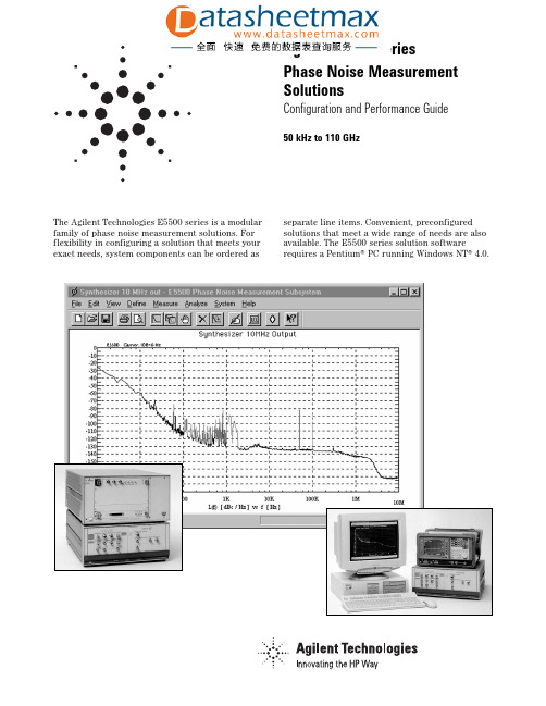
The Agilent Technologies E5500 series is a modular family of phase noise measurement solutions. For flexibility in configuring a solution that meets your exact needs, system components can be ordered as separate line items. Convenient, preconfigured solutions that meet a wide range of needs are also available. The E5500 series solution softwarerequires a Pentium® PC running Windows NT® 4.0.Agilent E5500 SeriesPhase Noise Measurement SolutionsConfiguration and Performance Guide50 kHz to 110 GHzATE Focused Preconfigured SolutionsE5501A 50 kHz to 1.6 GHz carrier frequencyE5502A 50 kHz to 6.0 GHz carrier frequencyE5503A 50 kHz to 18.0 GHz carrier frequencyE5504A 50 kHz to 26.5 GHz carrier frequencySolution components include:E1430A DC to 4 MHz VXI digitizerE1421B6-slot, high power VXI mainframe70420A MMS baseband phase noise test set70001A MMS mainframeE5480A LTU ACM softwareE5495A LTU remote SCPI client softwareHigh speed VXI-PC digital interfaceAgilent E5502/03/04A solutions also include a low noise 6, 18, or 26.5 GHz downconverter respectively.Option 001 add high power input capability (includes 26.5 GHz microwave phase detector and AM detector)Option 201add 26.5 GHz microwave phase detector onlyOption W30 add two additional years of return-to-Agilent serviceOption W50add four additional years of return-to-Agilent serviceOption +24D on-site customer training (contact SSV microwave systems engineer)Select a low noise RF reference source:Option 401add 8662A (includes E5485A LTU ACM software)Option 402 add 8663A (includes E5485A LTU ACM software)Option 403add 8643A (includes E5486A LTU ACM software)Option 404add 8644B (includes E5486A LTU ACM software)Option 405add 8644B/002 (includes E5486A LTU ACM software)Option 406add 8664A/004 (includes E5486A LTU ACM software)Option 407add 8665A/004 (includes E5486A LTU ACM software)Option 408add 8665B/004 (includes E5486A LTU ACM software)Option 409add ESG1000 (includes E5488A LTU ACM software)Option 410add 8657A (includes E5488A LTU ACM software)Select additional components:Option 420 add E1437A DC to 8 MHz digitizer (includes E5491A LTU ACM software)Option 430add E4411A 9 kHz to 1.5 GHz RFSA (includes E5483A LTU ACM software)Option 440add E1420B counter (includes E5492A LTU ACM software)Option S50add programmable delay lineOption N60add system rackOption F01add Pentium® PC with Windows NT®4.0 (specify exact requirements)Option N70add mm mixers and miscellaneous hardware2Benchtop Focused Preconfigured SolutionsE5501B 50 kHz to 1.6 GHz carrier frequencyE5502B50 kHz to 6.0 GHz carrier frequencyE5503B50 kHz to 18.0 GHz carrier frequencyE5504B50 kHz to 26.5 GHz carrier frequencySolution components include:E4411A 1.5 GHz RFSA70420A MMS baseband phase noise test set70001A MMS mainframeE5481A LTU ACM softwareE5483A LTU ACM softwarePentium® PC with Windows NT® 4.0 (32 MB ram, 1 GB hard drive, 82341C, digitizer)Agilent E5502/03/04B solutions also include a low noise 6, 18, or 26.5 GHz downconverter respectively.Option 001 add high power input capability (includes 26.5 GHz microwave phase detectorand AM detector)Option 110delete E4411A spectrum analyzer only Option 201add 26.5 GHz microwave phase detector onlyOption W30 add two additional years of return-to-Agilent serviceOption W50add four additional years of return-to-Agilent serviceOption +24D on-site customer training (contact SSV microwave systems engineer)Option 1FF delete computer and GPIB card only Select a low noise RF reference source:Option 401add 8662A (includes E5485A LTU ACM software)Option 402add 8663A (includes E5485A LTU ACM software)Option 403add 8643A (includes E5486A LTU ACM software)Option 404add 8644B (includes E5486A LTU ACM software)Option 405add 8644B/002 (includes E5486A LTU ACM software)Option 406add 8664A/004 (includes E5486A LTU ACM software)Option 407add 8665A/004 (includes E5486A LTU ACM software)Option 408add 8665B/004 (includes E5486A LTU ACM software)Option 409add ESG1000 (includes E5488A LTU ACM software)Option 410 add 8657A (includes E5488A LTU ACM software)Select additional components:Option S21 add 89410A DC to 10 MHz FFT analyzer (includes E5482A LTU ACM software) Option N31add 8560E RFSA (includes E5484A LTU ACM software)Option 440add 53181A counter (includes E5489A LTU ACM software)Option S50add programmable delay lineOption N60add system rackOption F01add Pentium® PC with Windows NT®4.0 (specify exact requirements)Option N20add E5495A LTU remote SCPI client softwareOption N70add mm mixers and miscellaneoushardware3Configuring a Specific Phase Noise Measurement SolutionAgilent E5500A ExxGeneric phase noise solution ordering convenience; must obtain a specific option quote from Agilent sales representative and factorySelect a baseband test set (required component):70420A50 kHz to 1.6 GHz carrier frequency four-slot MMS moduleOption 001 add high power input capability (includes 26.5 GHz microwave phase detectorand AM detector)Option 201 add 26.5 GHz microwave phase detector onlyMMS mainframe (one required):70001A MMS mainframeSelect a baseband analyzer and appropriate control software (required):89410A DC to 10 MHz analyzerE5482A LTU ACM software for 89410AE4411A 9 kHz to 1.5 GHz RFSAE5483A LTU ACM software for E4411AE1430A DC to 4 MHz digitizerE5480A LTU ACM software for E1430AE1437A DC to 8 MHz digitizerE5491A LTU ACM software for E1437A71209AE5484A LTU ACM software for 71000 series8560EE5484A LTU ACM software for 8560 series8563EE5484A LTU ACM software for 8560 seriesVXI mainframe (one required for E1430A or 1437A):E1421B 6-slot high power VXI mainframeE1401B 13-slot high power VXI mainframeHigh speed VXI-PC digital interface Select a low noise RF reference signal generator and appropriate control software (recommended):8662AE5485A LTU ACM software for 8662/63A8663AE5485A LTU ACM software for 8662/63A8643AE5486A LTU ACM software for 8643/44/64/658644BE5486A LTU ACM software for 8643/44/64/658664AE5486A LTU ACM software for 8643/44/64/658665AE5486A LTU ACM software for 8643/44/64/658642AE5487A LTU ACM software for 8642A/B8657AE5488A LTU ACM software for 8657AESG1000E5488A LTU ACM software for ESG seriesSelect a low noise microwave MMS downconverter:70422A 1 GHz to 18 GHz downconverter four-slot MMS module70427A 1.5 GHz to 26.5 GHz downconverter four-slot MMS moduleSelect other system components:E1420B frequency counterE5492A VXI frequency counter ACM53181A frequency counterE5489A frequency counter ACM for 531xx family programmable delay lineon-site customer traininginclude a Pentium® PCVXI E6490A series RF switch matrixMMS 70000series RF switch matrixsystem rackon-site installation4Determining Overall Solution Performance Measurement accuracyMeasurement of all noise and spurious present at the phase detector inputs and system contribution, provided the following conditions are met: Source return loss >9.5 dB (<2:1 VSWR)Source harmonic distortion <–20 dB (or square wave)Nonharmonic spurious <–26 dBc (except for PM close to carrier)Supported measurement configuration (PLL verification)±2 dB for <1.0 MHz offsets±4 dB for <100 MHz offsets Overall phase noise measurement system sensitivity is a combination of noise contributions from the baseband test set, the RF reference source, and the microwave downconverter used and is normally dominated by either the RF reference source or the microwave downconverter:Baseband test set + RF reference + microwave DC noise floor noise floor noise floorWhen the dominant noise contributions (RF refer-ence and the downconverter) are close to each other, a noise floor correction factor (dB) is added to the most dominant noise contributor in order to determine overall system noise floor:Magnitude 161063210 difference (dB)Noise 0.1 0.4 1.2 1.8 2.1 2.5 3 correctionfactor (dB)56Agilent 70420A Specification Summary(does not include phase noise and spurious signals from a reference source)Carrier frequency: 50 kHz to 1.6 GHz Offset frequency System noise floor 0.01 Hz 70 dBc/Hz 1.0 Hz 130 dBc/Hz 10 kHz 170 dBc/Hz >10 kHz 170 dBc/Hz Offset frequency Spurious response .01 Hz 70 dBc 0.1 Hz 100 dBc >10 Hz112 dBcCarrier frequency: 1.2 GHz to 26.5 GHz Offset frequency System noise floor 0.01 Hz 55 dBc/Hz 1.0 Hz 115 dBc/Hz 32 kHz 160 dBc/Hz >32 kHz 160 dBc/Hz Offset frequency Spurious response 0.01 Hz 50 dBc 0.1 Hz 80 dBc >10 kHz97 dBcGeneral specificationsOperating temperature range: +0 °C to +55 °C Warm-up time: 20 minutes General considerations:The 70420A has low susceptibility to RFI and mechanical vibration. Care must be exercised however in making measurements in high RFI or vibration environments as spurious signals may be induced in the module.Agilent 70421A Specification SummaryRF Input 1.0 GHz to 6.6 GHz IF output 5 MHz to 1.2 GHzIF output power0 to +5 dBmIF gain0 to 45 dB (5 dB steps)Input power+15 dBm max Mixing spurious (<+15 dBm at mixer)5 dBm min <6 GHz<50 dBc (except below)>6 GHz<70 dBcNoise figure 15 dB (typical)Carrier frequency range (GHz)Typicalwhere a mixing spur will occur spurious<100 MHz from carrier(dBc)LO resolution600 MHz (1.8 GHz to 6.0 GHz) 1.566 – 1.634, 1.166 – 1.23411.060 – 1.200, 1.274 – 1.303 201.325 – 1.375, 1.420 – 1.4601.775 – 1.8251.013 – 1.043, 1.250 – 1.043 301.900 – 1.940,2.225 – 2.2751.112 – 1.138, 1.483 – 1.517401.983 –2.017, 2.380 – 2.4202.483 – 2.517, 2.975 –3.0253.583 – 3.6172.556 – 2.586, 2.983 –3.017503.071 – 3.101Downconverter noise floor(all oscillators locked)Input Offset from carrier (Hz)frequency1101001k10k100k1M10M100M Spurious (dBc)<1k>1k 1.0 to Typical50809712513714314514514560753.0 GHz Specification45759212013213814014014050653.0 to Typical44749111913114314514514550806.6 GHz Specification3969861141261381401401404470 General specificationsOperating temperature range: +0 °C to +55 °CWarm-up time: 20 minutesGeneral considerations:The 70421A has low susceptibility to RFI and mechanicalvibration. Care must be exercised however, in makingmeasurements in high RFI or mechanical vibration environ-ments as spurious signals may be induced in the module.7Agilent 70422A specification summaryRF Input 1.0 GHz to 18 GHz IF output 5 MHz to 1.2 GHz(18 GHz to 20 GHz IF output power0 to +5 dBmtypical overrange)IF gain0 to 45 dB (5 dB steps)Input power+15 dBm max Mixing spurious (<+15 dBm at mixer)5 dBm min to 12 GHz<6 GHz<50 dBc (except below)10 dBm min to 18 GHz>6 GHz<70 dBcNoise figure 15 dB (typical)Carrier frequency range (GHz)Typicalwhere a mixing spur will occur spurious<100 MHz from carrier(dBc)LO resolution600 MHz (1.8 GHz to 18 GHz) 1.566–1.634, 1.166–1.234101.060–1.200, 1.274–1.303 201.325–1.375, 1.420–1.4601.775–1.8251.013–1.043, 1.250–1.043 301.900–1.940,2.225–2.2751.112–1.138, 1.483–1.517401.983–2.017, 2.380–2.4202.483–2.517, 2.975–3.0253.583–3.6172.556–2.586, 2.983–3.017503.071–3.101Downconverter noise floor(all oscillators locked)Input Offset from carrier (Hz)frequency1101001k10k100k1M10M100M Spurious (dBc)<1k>1k 1.0 to Typical5080971251371431451451456075 3.0 GHz Specification4575921201321381401401405065 3.0 to Typical4474911191311431451451455080 6.0 GHz Specification3969861141261381401401404470 6.0 to Typical3868851131251401401401405080 12.0 GHz Specification3363801081201351351351354070 12.0 to Typical3464811091211311311311314770 18.0 GHz Specification2959761041161261261261263760General specificationsOperating temperature range:+0 °C to +55 °CWarm-up time:20 minutesGeneral considerations:The 70422A has low susceptibility to RFI and mechanicalvibration. Care must be exercised however, in makingmeasurements in high RFI or mechanical vibrationenvironments as spurious signals may be induced inthe module.8Agilent 70427A specification summaryRF input 1.5 GHz to 26.5 GHz IF output 5 MHz to 1.2 GHzIF output power0 to +5 dBm (>30 dBm input)IF gain0 to 45 dB (5 dB steps)Input power+30 dBm max Mixing spurious (<+15 dBm at mixer)30 dBm min<6 GHz<50 dBc (except below)>6 GHz<70 dBcNoise figure 20 dB (typical)Carrier frequency range (GHz)Typicalwhere a mixing spur will occur spurious<100 MHz from carrier(dBc)Spectral purity for input signals <0 dBm, 1.586 – 1.61420noise at offsets >1 kHz may 1.790 – 1.81, 1.912 – 1.92830increase by 1 dB for every dB 2.392 – 2.408, 2.872 – 2.88830of input power reduction 2.990 – 3.00030LO resolution600 MHz (2.4 GHz – 25.8 GHz) 1.708 – 1.720, 1.993 – 2.00740O power0 to +16 dBm (2.4 – 6.6 GHz) 2.240 – 2.260, 2.493 – 2.507400 to +10 dBm (7.2 – 25.8 GHz) 2.737 – 2.749, 3.592 – 3.600402.051 – 2.063, 2.095 – 2.100502.565 – 2.578, 2.793 – 2.807503.000 – 3.007, 3.080 – 3.092503.493 – 3.507,4.108 – 4.120504.193 – 4.20050Downconverter noise floor(all oscillators locked)Input Offset from carrier (Hz)frequency1101001k10k100k1M10M100M Spurious (dBc)<100>1k1.5 to Typical508010012813814514514514560803.0 GHz Specification45759512313314014014014050653.0 to Typical44749412213414414714714750806.0 GHz Specification39698911712913914214214244706.0 to Typical3868881161281401431431435080 12.0 GHz Specification336383111123135138138138407012.0 to Typical3565851131251371401401404770 18.0 GHz Specification306080108120132135135135376018.0 to Typical3262821101221301301301304465 26.5 GHz Specification2757771051171251251251253455mm bands (when adding the 11970 series harmonic mixers)26 - 40Typical265676104116128130131131548033 - 50Typical265676104116128130131131447040 - 60Typical235373101113125127128128508050 - 75Typical235373101113125127128128407075 - 110Typical205070971091201221221224770General specificationsOperating temperature range: +0 °C to + 55 °CWarm-up time: 20 minutesGeneral considerations:The 70427A has low susceptibility to RFI and mechanicalvibration. Care must be exercised however, in makingmeasurements in high RFI or mechanical vibrationenvironments as spurious signals may be induced inthe module.9Agilent Technologies’ Test and MeasurementSupport, Services, and AssistanceAgilent Technologies aims to maximize the value you receive, while minimizing your risk and problems. We strive to ensure that you get the test and measurement capabilities you paidfor and obtain the support you need. Our extensive support resources and services can help you choose the right Agilent products for your applications and apply them successfully. Every instrument and system we sell has a global warranty. Support is available for at least five years beyond the produc-tion life of the product. Two concepts underlie Agilent’s overall support policy: “Our Promise” and “Your Advantage.”Our Promise“Our Promise” means your Agilent test and measurement equip-ment will meet its advertised performance and functionality. When you are choosing new equipment, we will help you with product information, including realistic performance specifica-tions and practical recommendations from experienced test engineers. When you use Agilent equipment, we can verify that it works properly, help with product operation, and provide basic measurement assistance for the use of specified capabili-ties, at no extra cost upon request. Many self-help tools are available.Your Advantage“Your Advantage” means that Agilent offers a wide range of additional expert test and measurement services, which you can purchase according to your unique technical and business needs. Solve problems efficiently and gain a competitive edge by contracting with us for calibration,extra-cost upgrades, out-of-warranty repairs, and on-site education and training, as well as design, system integration, project management, and other professional services. Experienced Agilent engineers and tech-nicians worldwide can help you maximize your productivity, optimize the return on investment of your Agilent instruments and systems, and obtain dependable measurement accuracyfor the life of those products.Pentium®is a U.S. registered trademark of Intel Corporation.Windows®is a U.S. registered trademark of Microsoft Corporation.By internet, phone, or fax, get assistance with all your test and measurement needs.Online Assistance/find/assistPhone or FaxUnited States:(tel) 1 800 452 4844Canada:(tel) 1 877 894 4414(fax) (905) 282 6495Europe:(tel) (31 20) 547 2323(fax) (31 20) 547 2390Japan:(tel) (81) 426 56 7832(fax) (81) 426 56 7840Latin America:(tel) (305) 269 7500(fax) (305) 269 7599Australia:(tel) 1 800 629 485(fax) (61 3) 9210 5947New Zealand:(tel) 0 800 738 378(fax) (64 4) 495 8950Asia Pacific:(tel) (852) 3197 7777(fax) (852) 2506 9284Product specifications and descriptions in thisdocument subject to change without notice.Copyright © 1998, 2000 Agilent TechnologiesPrinted in U.S.A. 10/005965-7589E。
抖动分析原理及安捷伦公司抖动分析解决方案

P3
0.980ns -0.030ns -0.020ns
(0.990/1.010/0.980/1.020)
P4
1.020ns 周期 0.040ns 周期到周期 0.000ns时间间隔误差
周期抖动 = 18.3ps RMS
周期到周期抖动 = 36.1ps RMS 时间间隔误差 = 9.6ps RMS
(0.020/-0.030/0.040)
2 1
4
Rise Fall
3
L_pkg C_comp R_pkg C_pkg
5
电路的不稳定性
PLL问题 同步开关噪声 互连阻抗不连续,互连损耗
上游的参考时钟
收发器发送的数据是以参考时钟为基准的,如果参考时钟
抖动过大。。。 使得抖动预估更困难 成为系统抖动
小结:抖动的成因
• 标准偏差 .
(所有测得的定时错误的RMS值).
• 峰 -峰值 .
(测得的定时错误的最大与最小值之差).
TIE的测量需要参考时钟.
常见的抖动术语小结
0.0ns 0.990ns 2.000ns 2.980ns 4.000ns
P1
0.990ns -0.010ns
P2
1.010ns 0.020ns 0.000ns
率噪声的方式显现出来。
目录
抖动的概念
抖动的成因 常见的抖动术语 抖动的分解 抖动测试分析方案
抖动的成因
热噪声
注入噪声
线路不稳定性 上游时钟
热噪声
随机性的 , 是多个随机抖动源的组合性现象 噪声所导致的抖动的分布是高斯与无边际的
注入噪声
确定性的, 能被确认为一些固有的成因 确定性抖动分布是有边际的,其频谱通常呈现为分离的谐波
抖动和眼图分析工具
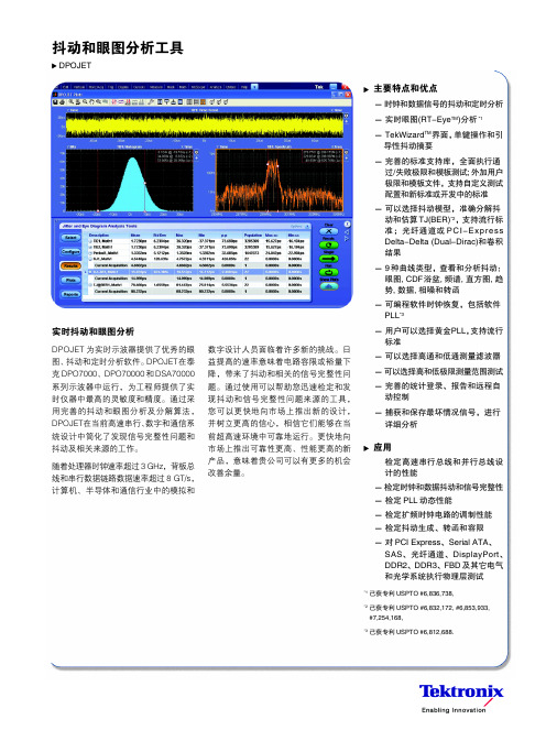
抖动和眼图分析工具DPOJET主要特点和优点- 时钟和数据信号的抖动和定时分析- 实时眼图(RT-Eye TM )分析*1- TekWizard TM 界面,单键操作和引 导性抖动摘要- 完善的标准支持库,全面执行通过/失败极限和模板测试; 外加用户极限和模板文件,支持自定义测试配置和新标准或开发中的标准- 可以选择抖动模型,准确分解抖动和估算TJ(BER)*2,支持流行标准;光纤通道或PCI-Express Delta-Delta (Dual-Dirac)和卷积结果- 9种曲线类型,查看和分析抖动:眼图, CDF浴盆, 频谱, 直方图, 趋势, 数据, 相噪和转函- 可编程软件时钟恢复,包括软件PLL *3- 用户可以选择黄金PLL,支持流行标准- 可以选择高通和低通测量滤波器- 可以选择高和低极限测量范围测试- 完善的统计登录、报告和远程自动控制- 捕获和保存最坏情况信号,进行详细分析应用检定高速串行总线和并行总线设计的性能- 检定时钟和数据抖动和信号完整性- 检定PLL 动态性能- 检定扩频时钟电路的调制性能- 检定抖动生成、转函和容限- 对PCI Express、Serial ATA、SAS、光纤通道、DisplayPort、DDR2、DDR3、FBD 及其它电气和光学系统执行物理层测试*1已获专利USPTO #6,836,738,*2已获专利USPTO #6,832,172, #6,853,933, #7,254,168,*3已获专利USPTO #6,812,688.实时抖动和眼图分析DPOJET 为实时示波器提供了优秀的眼图、抖动和定时分析软件。
DPOJET在泰克DPO7000、DPO70000和DSA70000系列示波器中运行,为工程师提供了实时仪器中最高的灵敏度和精度。
通过采用完善的抖动和眼图分析及分解算法,DPOJET在当前高速串行、数字和通信系统设计中简化了发现信号完整性问题和抖动及相关来源的工作。
AgilentEB频谱解析总结计划仪使用说明
Agilent E4402BESA-E Series Spectrum Analyzer使用方法简介宁波之猫2009-6-17目录1简介Agilent ESA-E系列是能适应将来需要的Agilent中性能频谱剖析仪解决方案。
该系列在丈量速度、动向范围、精度和功率分辨能力上,都为近似价位的产品成立了性能标准。
它灵巧的平台设计使研发、制造和现场服务工程师能自定义产品,以知足特定测试要求,和在需要时用新的特征升级产品。
该产品采纳单键丈量解决方案,并拥有易于阅读的用户界面和高速丈量的性能,使工程师能把较少的时间用于测试,而把更多的时间用在元件和产品的设计、制作和查错上。
2.面板操作区1.察看角度键,用于调理显示,以适于使用者的察看角度。
2.Esc 键,能够撤消输入,停止打印。
3.无表记键,实现左侧屏幕上紧挨的右侧栏菜单的功能。
4. Frequency Channel (频次通道)、Span X Scale(扫宽 X 刻度)和 AmplitudeY scale(幅度 Y 刻度)三个键,能够激活主要的调理功能(频次、X 轴、 Y 轴)并在右侧栏显示相应的菜单。
5.Control (控制)功能区。
6.Measure(丈量)功能区。
7.System(系统)功能区。
8.Marker (标志)功能区。
9.软驱和耳机插孔。
10.步进键和旋钮,用于改变所选中有效功能的数值。
11.音量调理。
12.外接键盘插口。
13.探头电源,为高阻抗沟通探头或其余附件供给电源。
14.Return 键,用于返回先前选择过的一级菜单。
15.Amptd Ref Out ,可供给- 20dBm 的 50MHz 幅度参照信号。
16.Tab(制表)键,用于在界线编写器和修正编写器中四周挪动,也用于在有 File 菜单键所接见对话框的域中挪动。
17.信号输进口(50Ω)。
在使用中,接 50Ω BNC 电缆,探头上一定串连一隔直电容( 30PF 左右,陶瓷封装)。
Agilent超宽带技术测试解决方案
Agilent超宽带技术测试解决方案一 UWB概述UWB(Ultra Wideband,超宽带)技术是一种短距离高速互联技术,起始于19世纪60年代,与传统通信技术不同,初期UWB不采用载波,而是通过纳秒至微微秒级的窄脉冲传输数据。
UWB技术工作在3.1GHz至10.6GHz频段,被分为14个频段,各频段宽528MHz,可见其带宽远宽于4G通信。
由于UWB有可能在某些频段与其它通信系统共存,因此对其频谱限制极严,其频谱类似于噪声,当存在UWB信号时,看上去像底噪略有提高。
图一 UWB频段图二 UWB频谱模版随着UWB技术的发展,UWB技术被分为两个阵营,分别是以Freescale为代表的UWB 论坛以及以Intel为代表的WiMedia联盟,而之前的标准制订组织IEEE 802.15.3a组织也已解散。
前者主推DS-UWB(直接序列超宽带),DS-UWB起步较早,主要应用在雷达和无线影像传输领域。
DS-UWB类似于802.11b DSSS(直接序列扩频),虽然是脉冲格式信号,但可以认为DS-UWB信号是超快速的BPSK或QPSK信号,其速率达28Mbps至1.32Gbps。
图三 DS-UWBWiMedia联盟主推MB-OFDM(多频段正交频分复用),发展较迅猛,目前在消费电子和PC领域具有优势,主要应用于无线USB领域,推出了Certified Wireless USB。
UWB以其低功耗、高速率的特点在无线个域网(WPAN)具有一定的优势,被认为是Bluetooth技术的替代。
MB-OFDM采用了OFDM技术,528MHz带宽信号由128个子载波组成,其中100个用于传输数据,12个子载波用于做导频,10个子载波起保护间隔作用,6个子载波不传输数据。
此外,MB-OFDM还采用了跳频技术,其跳频格式由TFC(Timing Frequency code)决定,有1-7种TFC。
MB-OFDM速率达53.3Mbps至480Mbps。
Agilent N9320B RF 頻譜分析儀 说明书
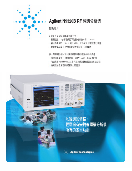
不論您的應用是電子產品製造、工作台上的維修、研發專案或RF相關教育,您都需要一款價格經濟,且配備必要功能與效能的頻譜分析儀。
Agilent N9320B正是為了滿足您的這項需求而設計。
,可讓您執行頻率響應量測。
(50 MHz,-10 dBm),供高阻抗RF探棒使用RF(N型,母座)Kensington TTL當您需要速度更快且更符合成本效益的RF分析工具,來測試現今的消費性電子產品與元件時,不必再考慮了!5當您發現自己必須反覆執行同一種複雜的量測或量測程序時,擁有一些捷徑能讓您聰明地提高效率。
這也是我們在Agilent N9320B 頻譜分析儀中,為您準備的功能。
Agilent N9320B 頻譜分析儀延續了安捷倫一貫堅持的傳統,就是測試設備應該具有容易設定且簡單好用的功能。
熟悉安捷倫其他頻譜分析儀的使用者會發現,Agilent N9320B 採用了類似的使用者介面,對於縮短學習曲線及簡化操作很有幫助。
單鍵自動調諧功能可以讓您在分析儀的頻率範圍內,迅速找到最高位準的信號,並且準確地加以分析。
將該信號置於螢幕中央,分析儀可同時將頻距、解析度和影像頻寬調整到最佳狀態,並且自動調整振幅的刻度、在信號峰值設定標記、及顯示量測結果。
單鍵功率量測功能簡化了按鍵/功能表的選擇,可以縮短例行的測試設定時間。
直接從軟鍵功能表選擇這些量測功能,也有助於確保不論是誰按的鍵,都不影響測試設定與量測的準確度和重測穩定度。
使用頻譜分析儀所執行的其中一項最基本的量測,就是在頻域中量測RF 功率。
但要詳細分析信號,通常需要進行標準所定義的頻譜遮罩測試,或更複雜的功率/頻寬/偵測器量測組合。
利用RMS 平均運算偵測器,精確而快速地計算出通道功率和功率頻譜密度。
選擇要量測的信號功率的百分比,即可將標記放在代表該功率百分比所使用頻寬的波形之高頻和低頻位置。
(ACP)可同時在最多6個偏移頻帶或通道,針對載波相對於載波洩漏,進行快速又準確的濾波式RMS 功率量測。
Agilent 87104 87106A B C多端口共振开关 dc到4 GHz、dc到20 GHz

Agilent 87104/87106A, B, CMultiport Coaxial Switchesdc to 4 GHz, dc to 20 GHz, dc to 26.5 GHzTechnical OverviewHigh performance multiportswitches for microwave and RFinstrumentation and systems• S P4T and SP6T confi guration• M agnetic latching• Operating life of 10 million cycles,typical• Guaranteed repeatability of 0.03dB up to 5 million cycles ensuresaccurate system measurementsand reduces calibration intervals• E xcellent isolation, typically>90 dB at 26.5 GHz• O pto-electronic indicators andinterrupts• T erminated ports• TTL/5 V CMOS compatible(optional)Modern automated test systems demand higher accuracy and performance than ever before. The Agilent Technologies 87104A/B/C and 87106A/B/C multiport switches offer improvements in insertion loss repeatability and isolation necessary to achieve higher test system perfor-mance. Long life, repeatability, and reliability lowers the cost of owner-ship by reducing calibration cycles and increasing test system uptime and are vital to ATS measurement system integrity over time.DescriptionThe 87104A/B/C SP4T and87106A/B/C SP6T terminated multi-port switches provide the life andreliability required for automatedtest and measurement, signal moni-toring, and routing applications.Innovative design and carefulprocess control creates switchesthat meet the requirements forhighly repeatable switching elementsin test instruments and switchinginterfaces. The switches are designedto operate for more than 10,000,000cycles. The exceptional 0.03-dBinsertion loss repeatability is war-ranted for 5 million cycles at 25°C.This reduces sources of randomerrors in the measurement path andimproves measurement uncertainty.Switch life is a critical considerationin production test systems, satelliteand antenna monitoring systems,and test instrumentation. The lon-gevity of these switches increasessystem uptime, and lowers the costof ownership by reducing calibrationcycles and switch maintenance.Operating to 4 GHz (A models),20 GHz (B models), and 26.5(C models), these switches exhibit exceptional isolation performance required to maintain measurement integrity. Isolation between ports is typically >100 dB to 12 GHz and>90 dB to 26.5 GHz. This reduces the influence of signals from other channels, sustains the integrity of the measured signal, and reduces system measurement uncertainties. These switches also minimize mea-surement uncertainty with low insertion loss and reflection, which make them ideal elements in large multi-tiered switching systems.Both the 87104A/B/C and87106A/B/C are designed to fall within most popular industry foot-prints. The 2¼ inch square flange provides mounting holes, while the rest of the 2½ inch long by 2¼ inch diameter body will easily fit into most systems. Ribbon cable or optional solder terminal connections accom-modate the need for secure and efficient control cable attachment. Option 100 provides solder terminal connections in place of the 16-pin ribbon drive cable. Option 100 does not incorporate the “open all paths” feature.Figure 1. Agilent 87104A/B/C and 87106A/B/C simplified schematicsOpto-electronic interrupts and indi-cators improve reliability and extendthe life of the switch by eliminatingDC circuit contact failures character-istic of conventional electromechani-cal switches. These switches have aninterrupt circuit that provides logicto open all but the selected ports,and then closes the selected paths.All other paths are terminated with50 ohm loads, and the current to allthe solenoids is then cut off. Theseversions also offer independent indi-cators that are controlled by opticalinterrupts in the switch. The indica-tors provide a closed path betweenthe indicator common pin and thecorresponding sense pin of theselected path.2ApplicationsMultiport switches find use in a large number of applications, increasing system flexibility and simplifying system design.Simple signal routingThe simplest signal routing scheme takes the form of single input to multiple outputs. These matrixes are often used on the front of an analyzer in order to test several two-port devices sequentially or for testing multiport devices. In surveillance applications, a multiport switch can be used for selecting the optimum antenna in order to intercept a signal. Two methods can be used to accom-plish the single input to multiple output arrangement. Traditionally where isolation greater than 60 dB was required, a tree matrix composed of SPDT switches was used. While this gave great isolation, it was at the cost of more switches (Figure 2). The 87104 and 87106 switches have port-to-port isolations typically greater than 90 dB at 26.5 GHz, eliminating the need to use a tree matrix in order to achieve high iso-lation (Figure 3). In addition to the reduced part count, the path lengths are shorter, so insertion loss is less, and paths are of equal length, so phase shift is constant.Full access switchingFull access switching systems givethe flexibility to route multiple inputsignals to multiple outputs simultane-ously. Full access switching matrixesfind use in generic test systems inorder to provide flexible routing ofsignals to and from many differentdevices under test and stimulus andanalysis instrumentation. Cross-pointmatrixes, using single pole doublethrow and cross-point switches, havetraditionally been used in order tomaintain high channel-to-channelisolation (Figure 4). As with the treematrixes, this is at the cost of hard-ware and performance. Full accessswitching can also be achieved usingmultiport switches (Figure 5).The advantage of the multiportmatrix over the cross-point matrixis lower insertion loss and improvedSWR performance due to consistentpath length and fewer switches andconnecting cables.Figure 2. Tree matrixFigure 3. Multiport matrixFigure 4. Cross-point matrixFigure 5. Full access matrix3Dedicated switchingThere are a number of applications where switching will be used, not for flexibility, but to accomplish a partic-ular function within an instrument. For example, switched filter banks for reducing harmonics in the output of sources or to the input of analyzers can use multiport switches in series to select the right filter for the band of interest. For larger switching systems, where many switches will be used to provide complex signal routing, a switch driver such asthe Agilent 11713B/C with 87204/6 switches is recommended.Driving the switchEach RF path can be closed by applying ground (TTL “High” for Option T24) to the corresponding “drive” pin. In general, all other RF paths are simultaneously opened by internal logic.Standard driveSee Figures 10 and 11 for drive connection diagrams.• C onnect pin 1 to supply (+20 VDC to +32 VDC)• C onnect pin 15 to ground(see Note 1).• S elect (close) desired RF pathby applying ground to the corre-sponding “drive” pin; for example ground pin 3 to close RF path 1 (see Note 2).• T o select another RF path, ensure that all unwanted RF path “drive” pins are disconnected from ground (to prevent multiple RF path engagement). Ground the “drive” pin which corresponds to the desired RF path (see Note 3).• T o open all RF paths, ensure thatall RF path “drive” pins are discon-nected from ground. Then, connectpin 16 to ground. Note: This featureis not available with Option 100.TTL drive (Option T24)See Figure 10 for drive connectiondiagrams.• C onnect pin 1 to supply(+20 VDC to +32 VDC)• C onnect pin 15 to ground(see Notes 1, 4).• S elect (close) desired RF path byapplying TTL “High” to the corre-sponding “drive” pin; for exampleapply TTL “High” to pin 3 to closeRF path 1 (see Note 2).• T o select another path, ensurethat all unwanted RF path “drive”pins are at TTL “Low” (to preventmultiple RF path engagement).Apply TTL “High” to the “drive”pin which corresponds to thedesired RF path (see Note 3).• T o open all RF paths, ensure thatall RF path “drive” pins are at TTL“Low.” Then, apply TTL “High” topin 16. Note: This feature is notavailable with Option 100.Notes:1. Pin 15 must always be connectedto ground to enable the electronicposition-indicating circuitry anddrive logic circuitry.CAUTION: IF PIN 15 IS NOTCON N ECTED TO POWER SUPPLYGROUND, CATASTROPHIC FAILUREWILL OCCUR.2. After the RF path is switched andlatched, the drive current is inter-rupted by the electronic position-sensing circuitry. Pulsed control isnot necessary, but if implemented,the pulse width must be 15 msmin i mum to ensure that theswitch is fully latched.3. The default operation of the switchis break-before-make. Make-before-break switching can be accom-plished by simultaneously selectingthe old RF path “drive” pin andthe new RF path “drive” pin. Thiswill simultaneously close the oldRF path and the new RF path.Once the new RF path is closed(15 ms), de-select the old RF path“drive” pin while leaving the newRF path “drive” pin selected. Theswitch circuitry will automaticallyopen the old RF path while leav-ing the new RF path engaged.4. In addition to the quiescentcurrent supplying the electronicposition-sensing circuitry, thedrive current flows out of pin 15(during switching) on TTL driveswitches (Option T24).4Electronic position indicatorsconsist of optically isolated, solid-state relays which are driven byphoto-electric sensors coupled to themechanical position of the RF path’smoving elements (Figure 6). The cir-cuitry consists of a common whichcan be connected to an output corre-sponding to each RF path. If multipleRF paths are engaged, the positionindicator corresponding to eachclosed RF path will be con n ected tocommon. The solid state relays areconfigured for AC and/or DC opera-tion. (See indicator specifications.)The electronic position indicatorsrequire that the supply (20 to 32 VDC)be connected to pin 1 and groundconnected to pin 15.Figure 6. Pin function diagram* Paths 1 and 4 are not connected for the87104A/B/C5SpecificationsSpecifi cations describe the instru-ment’s warranted performance. Supplemental and typical charac-teristics are intended to provide information useful in applying the instrument by giving typical, but not warranted performance parameters. Life: 5,000,000 cycles minimum Switching speed: 15 ms maximum Indicator specifications Maximum withstand voltage: 60 V Maximum current capacity: 150 mA Maximum “ON” resistance: 2.5 ΩMaximum “OFF” resistance: 10 G Ω675-10152025Freq. (GHz)5I s o l a t i o n (d B )010152025Freq. (GHz)Figure 8. Isolation8Environmental specificationsMaximum power rating:Into internal termination: 1W CW50W peak, 10us max pulse width, not to exceed 1W average Into thru path:Hot switching: 2W CW100W peak, 10us max pulse width, not to exceed 2W average Cold switching: See “Supplement Specifications (Cold Switching)”Operating temperature: –25 to 75°C Storage temperature: –55 to 85°C Temperature cycling: –55 to 85°C,10 cycles per MIL-STD-202F, Method 107D, Condition A (modified)Vibration:Operating: 7 g: 5 to 2000 Hz at 0.25 in p-pSurvival: 20 g: 20 to 2000 Hz at 0.06 in p-p,4 min/cycle, 4 cycles/axisRandom: 2.41 g (rms) 10 min/axis Shock: Half-sine: 500 g at 0.5 ms, 3 drops/direction, 18 totalOperating: 50 g at 6 ms, 6 directions Moisture resistance: 65°C, 95% RH, 10 days per MIL-STD-202F, Method 106EAltitude storage: 50,000 feet (15,240 meters per MIL-STD-202F, Method 105C, Condition B)RFI: Per MIL-STD-461C, RE02, Part 4Magnetic field: <5 gauss 1/4 inch from surfacePhysical specificationsDimensions: Per Figure 9Weight: 229 gm (0.50 lb)Supplemental Specifications (Cold Switching)Reference conditions:• Cold switching only (NO Hot switching)• Ambient temperature of 75°C or less • Sea level (0.88 derating @ 15,000 ft.)• Load VSWR < 1.2 (see graph for derating above 1.2 VSWR)*Power Handling at 25° C is 100 W at 4 GHz910TroubleshootingSymptomProbable cause1. Will not switch• Not connected to supply • Supply <20 V• Supply current too low • Not connected to ground• Select line not at ground (std)• TTL “Low” voltage too high (Option 72)• All-path-open line selected 2. Position indicators don’t work• Supply not connected • Supply <20 VDC• Pin 15 not connected to groundFigure 11. Drive connection diagramswith Option 100* Paths 1 and 4 not connected for the 87104A/B/C.** “Open all paths” pin is not available.Figure 10. Drive connection diagrams with Option 161Ordering informationSwitches87104A dc to 4 GHz, SP4T Terminated87104B dc to 20 GHz, SP4T Terminated87104C dc to 26.5 GHz, SP4T Terminated87106A dc to 4 GHz, SP6T Terminated87106B dc to 20 GHz, SP6T Terminated87106C dc to 26.5 GHz, SP6T TerminatedOption 100Solder terminals to replace ribbon cableOption 16116 PIN DIP socket and connector with 24 inch ribbon cableOption UK6Commercial calibration test data with certificateOption T24TTL/5 V CMOS compatible optionDrivers11713B/C Attenuator switch driverDrives up to 10 or more sections of switches or attenuators.Option 201 Accessory cableViking connector to bare tinned wires (60 inches long).Use to connect 11713B/C to 87104/106 with Option 100.One required with 87104A/B/C Option 100;two required with 87106A/B/C Option 100.Option 401 Accessory cableDual-viking connector to 16-pin DIP connector.Use to connect 11713B/C to 87106 default Option 161.Option 601 Accessory cableViking connector to 16-pin DIP connector.Use to connect 11713B/C to 87104 default Option 161.Related LiteratureAgilent RF and Microwave Switch Selection Guide, literature number 5989-6031ENPower Handling Capability of Electromechanical Switches, literature number 5989-6032ENHow Operating Life and Repeatability of Agilent’s Electromechanical Switches Minimize SystemUncertainty, literature number 5989-6085ENAgilent RF & Microwave Switches Performance you can count on, literature number 5989-6947ENAgilent 11713B/C Attenuator/Switch Drivers Configuration Guide, literure number 5989-7277EN.Multiport Solutions for E5071C ENA RF Network Analyzers Using External Switches, literaturenumber 5989-7916ENAgilent Technologies Bench and System Switching Products, literature number 5989-9872EN11For more information on Agilent T echnologies’ products, applications or services, please contact your local Agilent office. The complete list is available at:/find/contactus AmericasCanada (877) 894 4414 Brazil (11) 4197 3500Latin America 305 269 7500Mexico 01800 5064 800United States (800) 829 4444Asia Pacific Australia 1 800 629 485China800 810 0189Hong Kong 800 938 693India 1 800 112 929Japan 0120 (421) 345Korea 080 769 0800Malaysia 1 800 888 848Singapore 180****8100Taiwan 0800 047 866Thailand1 800 226 008Europe & Middle East Austria 43 (0) 1 360 277 1571Belgium 32 (0) 2 404 93 40 Denmark 45 70 13 15 15Finland 358 (0) 10 855 2100France 0825 010 700**0.125 €/minuteGermany 49 (0) 7031 464 6333 Ireland 1890 924 204Israel 972-3-9288-504/544Italy 39 02 92 60 8484Netherlands 31 (0) 20 547 2111Spain 34 (91) 631 3300Sweden 0200-88 22 55Switzerland 0800 80 53 53United Kingdom 44 (0) 118 9276201Other European Countries:/find/contactusRevised: July 8, 2010Product specifications and descriptions in this document subject to change without notice.© Agilent Technologies, Inc. 2010Printed in USA, August 23, 20105091-3366E/find/mtaAgilent Email Updates/find/emailupdates Get the latest information on the products and applications you select.LXI is the LAN-based successor to GPIB, providing faster, more efficient connectivity. Agilent is a founding member of the LXI consortium.Agilent Channel Partnersw w w /find/channelpartners Get the best of both worlds: Agilent’s measurement expertise and product breadth, combined with channel partner convenience.Agilent Advantage Services is com-mitted to your success throughout your equipment’s lifetime. We share measurement and service expertise to help you create the products that change our world. To keep you com-petitive, we continually invest in tools and processes that speed up calibra-tion and repair, reduce your cost of ownership, and move us ahead of your development curve./quality/find/advantageservices。
安捷伦Agilent仪器常见故障及预防措施

安捷伦Agilent仪器常见故障及预防措施
你是否持有安捷伦的仪器?对仪器的故障现象、可能原因和预防措施还不够了解?来看看以下这些型号的原因分析。
故障现象
开机只有一个台阶状的噪底,高端信号测试低10甚至20dBm。
测试过程中出现衰减值混乱、非线性。
可能原因
该故障多半是由于校准常数丢失造成的,而校准常数的丢失或是因为存储器电池失效、或是在做自校过程中突然掉电造成所有补偿数据复位。
极有可能是输入衰减器的射频衰减片被烧毁造成的。
预防措施
建议用户定期通过维修部更换(检测)电池。
另外,在做自校过程中杜绝人为的复位、断电等操作。
防止直流信号及大信号的接入。
故障现象
开机直通状态下的传输测量正常,单通道测量低3-5dBm。
回波损耗曲线异常。
开机直通状态下的传输测试曲线呈反抛物线状。
可能原因
极有可能是由于遭受大信号或强静电的侵入,接收机的元件被击穿造成的。
可能是信号输入端的保护器被烧毁。
预防措施
对接入网络分析仪测试端的被测信号进行预测试。
完善防静电设施及步骤。
Agilent-86100A眼图仪设定指引内容
Agilent-86100A眼图仪设定指引内容Agilent 86100设定指引内容设定指引是您可以使用仪器去执行许多一般工作的逐步程序1、NRZ眼图2、RZ眼图3、示波器量测4、TDR/TDT量测5、模板测试6、校准7、设定和使用印表机8、管理的档案NRZ眼图量测设定指引设定指引是您可以使用仪器去执行许多一般工作的逐步程序1、消减率2、颤动3、平均功率4、交叉百分比5、上升时间6、下降时间7、位元率8、0位准9、1位准10、眼状高度11、眼状宽度12、信噪比13、信号周期失真14、眼状振幅消减率概念您可以量测NRZ肯眼图的消减率。
消减率是眼图的1位准和0位准比率1、选择NRZ的Eye/Mask(眼状./模板)模式2、执行消减率校准3、定义眼状视窗界限。
4、定义量测单位5、执行消减率量测选择NRZ眼状/模板模式A)按仪器前面板上的Eye /Mask Mode(眼状/模板模式)按钮。
您也可以开启(Setup(设定)功能表然后按一下/轻触Eye /Mask Mode。
B)如果仪器处于RZ眼状模式,请按一下/轻触位于仪器工具列底下的RZ/NRZ按钮以显示NRZ眼状模式量测C)按仪器前纲板上的Autoscale (自动刻度选择)按钮以便快带将眼图的水平和垂直的水平和垂直刻度最佳化。
您也可以开启Control(控制)功能表然后按一下/轻触Autoscale.执行减率校准执行消减率校准A)在Cakuvrate(校准)功能表上选择All Calibrations(所有校准)。
All Calibrations(所有校准)对话方会开启。
B)按一下/轻触Extinction ratio(消减率)标识。
消减率标识页面开启并允许您在仪器频道之一减謴校准确。
C)移除所有至即将进行校准频道的讯号D)按一下/轻触(Calibrate (校准)。
将会出现进度表作为校准状太的目测指示器E)完成校准时按一下/轻触Close关闭。
定义眼状视窗界限A)请在Measure(测量)功能表选取Configure Meas (设定量测)。
数采(Agilent)参数设定操作
数采(Agilent)参数设定操作:A:数采的通信设定如下:1.打开数采电源。
2.按数采面板上的"Shift"键;3.再按"Sto/Rcl"键;调节旋转按钮,使屏幕显示"RS-232"4.再按"Sto/Rcl"键;调节旋转按钮,使屏幕显示"57600"5.再按"Sto/Rcl"键;调节旋转按钮,使屏幕显示"NONE;8BITS"6.再按"Sto/Rcl"键;调节旋转按钮,使屏幕显示"FLOWXON/XOFF"7.再按"Sto/Rcl"键;屏幕会自动显示"NOCHANGES";设定完成.B:数采时间参数设定如下:1.按"Interval"键;调节旋转按钮,使屏幕显示"INTERVALSCAN"2.再按"Interval"键;调节旋转按钮,使屏幕显示"H:M:S:00:00:20。
000"3.再按"Interval"键;调节旋转按钮,使屏幕显示"0001 SCAN"4.再按"Interval"键;屏幕会自动显示"NOCHANGES"或"DONE";设定完成.C:数采热电偶参数设定如下:(101-118通道号)例:设定101通道热电偶参数如下,1.调节旋转按钮,使屏幕显示"101通道"2.按"Measure"键;调节旋转按钮,使屏幕显示"TEMPERATURE"3.再按"Measure"键;调节旋转按钮,使屏幕显示"THERMUCOUPCE"4.再按"Measure"键;调节旋转按钮,使屏幕显示"T TYPE T/C"5.再按"Measure"键;调节旋转按钮,使屏幕显示"UNITS℃"6.再按"Measure"键;调节旋转按钮,使屏幕显示"DISPLAY0.1℃"7.再按"Measure"键;屏幕会自动显示"NOCHANGES";设定完成。
{注:102-118通道的热电偶参数按上述[C项:数采热电偶参数设定如下:(101-118通道号)]步骤操作}附:设定参数时,只需设定(A项:数采的通信设定如下B项:数采时间参数设定如下);若热电偶参数设定有误,再按照(C项:数采热电偶参数设定如下:(101-118通道号)进行设定。
示波器进行时钟抖动测试的精度
示波器进行时钟抖动测试的精度分析抖动是指数字信号中不期望的相位调制,同时也是衡量高速数字信号质量的最重要的指标。
现在各种通信标准都对通信设备的抖动的指标有严格的要求,各种总线的一致性测试中也会对随机抖动、确定性抖动、时间间隔误差、总体抖动等有要求。
示波器是很强大的工具,目前很多windows平台的示波器都提供了一些抖动分析的软件,可以提供直方图、时间图、抖动频谱、RJ/ DJ分解、浴盆曲线等一系列漂亮的测试报告。
但是事实上,很多用户在使用示波器进行精确抖动测量时却不能得到很好的结果。
比如明明要求被测时钟的抖动小于0.5ps RMS,实际测出来却是5ps RMS,数量级的错误使得很多用户开始怀疑测量结果和测量方法的可信程度。
这些错误结果的出现除了部分是由于对抖动概念理解不够从而设置错误外,还有很大一部分原因是不了解所使用的示波器的抖动测量能力,也就是您在使用的这台示波器究竟能测量到多小的抖动,以及和那些因素有关。
衡量示波器实际能测量到的最小的抖动的指标是抖动测量本底(J itter measurement floor)。
如果被测件的实际抖动小于示波器的抖动测量本底,这些抖动是不可能被测量到的。
抖动测量本底这个指标和示波器的采样时钟抖动、底噪声以及被测信号都有关系,其表现为示波器对测量结果增加的随机抖动的大小。
由于不同示波器厂商用不同的方法定义抖动测量本底,这就要求购买或使用示波器的工程师深入理解不同指标定义的含义。
通常用来衡量示波器抖动测量能力的指标有2个:固有抖动(Int rinsic Jitter)和抖动测量本底(Jitter Measurement Floor)。
这2个指标间有关系但又不完全一样,下面就来解释一下。
1、固有抖动示波器的固有抖动,有时又叫采样时钟抖动,是指由于示波器内部采样时钟误差所造成的抖动。
由于现在高带宽示波器的采样时钟频率都非常高,可高达80G/s或者更高,因此要保证每一个实际的采样点都落在其应该在的理想位置是个非常有挑战性的工作。
安捷伦气相色谱仪基线问题
安捷伦气相色谱仪基线问题
气相色谱基线波动、飘移都是基线问题,基线问题可使测量误差增大,有时甚至会导致仪器无法正常使用。
1、遇到基线问题时应先检查仪器条件是否有改变,近期是否新换气瓶及设备配件。
2、如果有更换或条件有改变,则要先检查基线问题是不是由这些改变造成的,一般来说,这种变化往往是产生基线问题的原因。
有些人在工作中就遇到过这种情形:新载气纯度不够,换过载气之后,基线逐渐上升(由于载气净化管的原因,基线不是马上变化的)。
第二天开机之后,基线非常高,并伴有基线强烈抖动,所有峰都湮没在噪音中,无法检测。
经过检查,问题出现在新换的载气上,重新更换载气后,立即恢复了正常。
3、当排除了以上可能造成基线问题的原因后,则应当检查进样垫是否老化(应养成定期更换进样垫的好习惯);
4、石英棉是不是该更换了;
5、衬管是否清洁。
值得一提的是,清洗衬管时可先用试验定容的溶剂充分浸泡,再用超声波清洗几分钟,然后放入高温炉中加热到比工作温度略高的温度,再重新安装。
6、此外,检测器污染也可能造成基线问题,其可以通过清洗或热清洗的方法来解决。
1。
AgilentGC-MS7890B5977性能参数
8、 微池电子捕获检测器(micro-ECD):对电负性化合物(如含卤素的有机化合物):1)、带电子气路 控制,控制精度:0.001Psi
2)、最低检测限:<6fg/mL林丹
3)、独有的信号线性化
4)、线性动态范围:对林丹>5X10⁴
5)、数据采集速率:最大50Hz
6)、放射源:<15mCi的63Ni
Agilent GC-MS 7890B 5977性能参数
安捷伦7890B-5977气质联用仪
1
技术参数
(一)质谱部分:
1、 质谱性能1)、全自动调谐
2)、质量数范围:1.6-1050amu,以mu递增
3)、分辨率:单质量数分辨
4)、质量轴稳定性:不劣于0.10amu/48小时
5)、灵敏度:
全扫描灵敏度(电子轰击源):1pg八氟萘,信/噪比>400:1(扫描范围:50-300amu)
7)、可使用填充柱/毛细管柱通用或优化于毛细管柱的类型
8)、最高使用温度:400弋
10、吹扫捕集(Tekmar)
11.1整合了自动进样和吹扫捕集到一体机上,处理固/液体样品中挥发性有机化合物。
11.2、 系统采用甲醇提取自动化功能,针对高浓度土壤样品,符合美国国家环保局方法5035。
11.3、吹扫捕集浓缩仪具有自动干燥除湿功能,同时不得流失分析的有机组分。
11.6、*自动进样器80位;处理固/液体样品中挥发性有机化合物
12、仪器控制及数据处理系统:1)、硬件:与仪器适配商用计算机和激光打印机
2)、软件:
3)、Windows操作环境中运行,具仪器控制、数据采集、数据分析、结果报告等基本功能
4)、气相色谱软件符合GLP/GMP勺要求
- 1、下载文档前请自行甄别文档内容的完整性,平台不提供额外的编辑、内容补充、找答案等附加服务。
- 2、"仅部分预览"的文档,不可在线预览部分如存在完整性等问题,可反馈申请退款(可完整预览的文档不适用该条件!)。
- 3、如文档侵犯您的权益,请联系客服反馈,我们会尽快为您处理(人工客服工作时间:9:00-18:30)。
Agilent——眼图、抖动、相噪随着数据速率超过Gb/s水平,工程师必须能够识别和解决抖动问题。
抖动是在高速数据传输线中导致误码的定时噪声。
如果系统的数据速率提高,在几秒内测得的抖动幅度会大体不变,但在位周期的几分之一时间内测量时,它会随着数据速率成比例提高,进而导致误码。
新兴技术要求误码率(BER),亦即误码数量与传输的总码数之比,低于一万亿分之一(10-12)。
随着数据通信、总线和底板的数据速率提高,市场上已经出现许多不同的抖动检定技术,这些技术采用各种不同的实验室设备,包括实时数字示波器、取样时间间隔分析仪(TIA)、等时取样示波器、模拟相位检波器和误码率测试仪(BERT)。
为解决高数据速率上难以解决的抖动问题,工程师必需理解同步和异步网络中使用的各种抖动分析技术本文重点介绍3 Gb/s以上新兴技术的数据速率。
低于3 Gb/s的实时示波器可以捕获连续的数据流,可以同时在时域和频域中分析数据流;在更高的数据速率上,抖动分析要更具挑战性。
本文将从数字工程师的角度,介绍应对SONET/SDH挑战的各种经验。
抖动分析基本上包括比较抖动时钟信号和参考时钟信号。
参考时钟是一种单独的黄金标准时钟,或从数据中重建的时钟。
在高数据速率时,分析每个时钟的唯一技术是位检测和误码率测试;其它技术则采用某种取样技术。
如图1所示,眼图是逻辑脉冲的重叠。
它为测量信号质量提供了一种有用的工具,即使在极高的数据速率时,也可以在等时取样示波器上简便生成。
边沿由‘1’到‘0’转换和‘0’到‘1’转换组成,样点位于眼图的中心。
如果电压(或功率)高于样点,则码被标为逻辑‘1’;如果低于样点,则标为‘0’。
系统时钟决定着各个位的样点水平位置。
图1: 具有各项定义的眼图E1是逻辑‘1’的平均电压或功率电平,E0是逻辑‘0’的平均电压或功率电平。
参考点t = 0在左边的交点进行选择,右边的交点及其后是位周期TB。
Eye Crossing Point: 眼图交点Left Edge: 左沿Right Edge: 右沿Nominal Sampling Point: 标称样点幅度噪声可能会导致逻辑‘1’的电压或功率电平垂直波动,低于样点,导致逻辑‘1’码错误地标为逻辑‘0’码,即误码。
抖动描述了相同的效应,但它是水平波动。
抖动或定时噪声可能会导致码的边沿在水平方向中的样点内波动,导致错误。
从这种意义上讲,抖动定义为一个数字信号在有效时点上距理想时间位置的短期变化。
脉冲电压电平的波动源自不需要的调幅(AM)。
类似的,转换的定时波动可以描述为脉冲相位波动、不需要的调相(PM)或相噪。
在系统器件的定时方面,数据通信和电信技术并不相同。
在同步系统中,如SONET/SDH,系统器件同步到公共的系统时钟。
在信号通过网络传送时,不同器件生成的抖动会通过网络传播,除非对器件中传送的抖动提出严格的要求,否则抖动可能会无限制地提高。
在异步系统中,如千兆位以太网、PCI Express和光纤通道,器件定时由分布式时钟提供或从数据转换中重建的时钟中提供。
在这种情况下,必须限制器件生成的抖动,但从一个器件转移到另一个器件上的抖动则不太重要。
不管是哪种情况,底线是系统的工作性能如何,即误码率。
图2: 抖动大的眼图的交点,直方图是一个像素宽的交点块投射到时间轴上的投影器件生成的固有抖动称为抖动输出。
其主要来源可以分为两个:随机抖动(RJ)和确定性抖动(DJ)。
可以把抖动看作从理想定时位置的、逻辑转换的定时变化,如图2中的直方图所示。
这一分布显示了被不同抖动源模糊的理想定时位置。
抖动分布是RJ和DJ概率密度函数的卷积。
随机抖动源自各种随机流程,如热噪声和散粒噪声,其假设遵守高斯分布,如图3a所示。
由于高斯分布的尾部扩展到无穷大,RJ的峰到峰值没有边界,而RJ的均方根则收敛到高斯分布的宽度上。
图3: 单个时点的抖动、正弦周期抖动和随机抖动相结合,导致误码的实例Ideal Transition Edge: 理想的转换边沿RJ Smeared Edge: RJ模糊的边沿DJ Smeared Edge: DJ模糊的边沿确定性抖动(DJ)包括占空比失真(DCD)、码间干扰(ISI)、正弦或周期抖动(PJ)和串扰。
DCD源自时钟周期中的不对称性。
ISI源自由于数据相关效应和色散导致的边沿响应变化。
PJ源自周期来源的电磁捡拾,如电源馈通。
串扰是由捡拾其它信号导致的。
DJ的特色特点是,其峰到峰值具有上下限。
DCD和ISI称为有界相关抖动;Pj和串扰称为不相关有界抖动;RJ称为不相关无界抖动。
识别不同类型的抖动来源,可以减少设计层次的问题,因为不同的器件以不同的方式生成抖动。
例如,发射机主要生成RJ。
外部调制的激光发射机生成的大多数抖动是由激光器和主参考时钟的随机抖动导致的。
相反,接收机生成的绝大部分抖动是DJ,这源于导致ISI的前置放大器和后置放大器连接的AC耦合等因素。
直接调制激光发射机受到RJ和DJ的影响。
介质采用两种方式:光纤从色散中增加DJ,从散射中增加RJ;传导介质从有限带宽中增加DJ,与低频和多个反射相比,高频的衰减要更高。
很重要的一点是,要理解抖动分布是由所有抖动源的卷积赋予的。
为直观地认识抖动,我们考察一下从‘0’到‘1’的逻辑转换,如图3b所示。
标有‘x’的样点距理想转换边沿右面位周期的一半。
现在,增加幅度为A的正弦DJ。
在波的顶部,边沿从理想边沿朝着样点移动距离A。
然后,根据高斯分布模糊边沿的位置,增加RJ。
如果边沿移到样点的右面,那么逻辑‘1’码被错误地标为‘0’。
在这种情况下,码边沿抖动经过样点的部分时间决定着BER。
如果已知抖动原因,则可以计算BER。
在本例中,抖动是RJ及PJ的一个来源,PJ移动边沿距离A及呈高斯分布的区域(图3a中的阴影部分),移到样点右面的概率决定着误码概率。
这展示了RJ 和DJ分布怎样一起卷积,即一种原因的效应叠加在另一种原因的效应之上,直到考虑了所有原因。
衡量系统功能的最终尺度是BER。
抖动分析的目标是确定抖动对BER的影响,并保证系统BER低于某个最大值,通常是10-12。
BER(T)由码型发生器、误码分析仪和系统时钟组成。
数据发生器把码型传送到系统器件上。
器件处理码型,把结果传送到误码分析仪,误码分析仪在已知码型上同步,计算收到的码数,确定哪些码接收错误,计算BER。
图4是BER图,它是样点时间位置BER(t)的函数,这个图称为BERT扫描图或浴缸曲线,简而言之,它在相对于参考时钟给定的额定取样时间的不同时间t上测得的BER。
参考时钟可以是信号发射机时钟,也可以是从接收的信号中恢复的时钟,具体取决于测试的系统。
图4的时间轴与图1相同,两侧与眼图边沿相对应,样点位于中心。
BER一定时,曲线之间的距离是该BER上的眼图张开程度。
在样点接近交点时,抖动会导致BER提高到最大0.5。
完整的BERT扫描测量是直接衡量BER一定时眼图张开程度的唯一方法。
遗憾的是,完整的BERT扫描图需要很长的时间,如在5 Gb/s时需要30分钟。
通过集中在眼图边沿进行部分BERT扫描,可以在几秒内,在10-15%的范围内保守地估算任何BER时的眼图张开程度。
估算技术是一种近似方式,它对RJ和DJ概率分布去卷积,然后或多或少地使用高斯RJ,根据图3所示计算BER。
关键在于,由于DJ有界、RJ是高斯分布,卷积的分布尾部在BER下限中遵守高斯RJ分布。
从高斯分布中推导出的函数,称为互补误差函数,拟合到BERT扫描平滑的下降沿上。
然后可以推断拟合的函数,直到任何BER值,以估算眼宽。
图4: BER(T)扫描或浴缸曲线,其中误码率是样点时间位置的函数Bit Error Rati 误码率Eye Width at BER = 10-12: BER = 10-12时的眼宽Time, t, relative to the reference clock: 相对于参考时钟的时间t等时取样示波器上显示的眼图由从多个不同逻辑脉冲上取样的数据组成。
“轨迹”由参考时钟提供的触发之后的顺序时间上采集的数据点组成。
显示的是一个两维直方图,如图1和图2所示。
某个点上的颜色或亮度用来衡量该电压或功率上相对于触发信号的时间上发生的样点数量。
取样示波器可以把一个像素宽的交点块投到时间轴上,构成眼图交点直方图(图2),测量抖动输出。
眼图交点直方图近似计算信号抖动输出的概率分布函数。
在BERT扫描情况下,通过对RJ和DJ近似去卷积,可以从眼图交点直方图中估算BER,这基于这样一个事实,即在远离交点时,抖动分布主要取决于高斯RJ。
把直方图的尾部与高斯分布匹配起来,提供了一个函数,然后可以在眼图中推断这个函数,并用来估算BER一定时的眼宽。
数据集合和分析与高速取样时间间隔分析仪中基本相同。
交点直方图拟合的宗旨与拟合BERT扫描的宗旨类似,但BERT扫描技术的速度和精度都要高得多。
通过拟合直方图获得的某种高斯形状在一定程度上受到随机波动的影响;BERT扫描只取决于数据转换是否在样点上波动,而不取决于其波动的精确时间位置。
因此,使用BERT进行测量要比低概率波动强健得多,后者的拟合可能会偏向交点直方图。
部分BERT扫描的拟合速度要比交点直方图的拟合速度快得多,因为BERT数据集是在完整的数据速率上采集的,而直方图则是通过以低得多的速率对信号取样构建的。
对于高斯RJ能否精确地描绘交点直方图或BERT扫描的低BER的尾部,人们还存在争议。
这种真正的随机流程会导致抖动,抖动遵守高斯分布并不存在问题,但这些流程可能并不是抖动分布尾部的主要因素。
问题在于,多种小的效应之和,会构成接近高斯的分布。
统计理论的中心极限定理体现了这一点:数量无穷大的小流程之和会遵守高斯分布。
这意味着多个低幅度的DJ流程会卷积到一个仅在钟形曲线中心、而不是尾部接近高斯分布的分布函数。
但是尾部才是高斯假设对估算BER最重要的地方。
可能在某些情况下,真正的RJ只占似乎是高斯分布的抖动的一小部分。
如果是这样,那么用来从拟合快速BERT扫描测量和直方图拟合中估算BER所使用的技术,可能会在总体上高估实际BER。
尽管近似方法总是要小心出现错误,但在高斯分布没有很好地描述尾部时,它可能会迫使制造商设计的抖动余量超过必要的水平。
幸运的是,通过以BER = 10-12的误码率水平执行全面的BERT扫描测量,进而可以把拟合技术与整个测量进行对比,检查这种情况并不难。
在抖动分析中,有两个不同的频域:时钟频率定义了时钟信号的额定交叉时间,抖动频率则是相对于额定交叉时间,时钟交叉的时间位置变化的频域。
例如,周期抖动会导致时钟信号变化大约额定的时钟交叉量。
结果,数据信号的抖动频率限于低于时钟频率的一半。
分析解调的抖动信号或相噪是一种强大的诊断技术。
