MCR50中文资料
MCR01MZPJ中文资料

ResistorsRev.B 1/5Thick film rectangularMCR01 (1005 size : 1 / 16W )z Features1) Extremely small lightArea ratio is 60% smaller than that of chip 1608, while weight ratio has been cut 75%. 2) Highly reliable chip resistorRuthenium oxide dielectric offers superior resistance to the elements. 3) Electrodes not corroded by solderingThick film makes the electrodes very strong. 4) Flat surface further facilitates mounting Mounting can also be automated.5) ROHM resistors have approved ISO–9001 certification.Design and specifications are subject to change without notice. Carefully check the specification sheet supplied with the product before using or ordering it.z Ratings0.063W (1 / 16W)−55°C to +155°Cat 70°CPower must be derated according to the power derating curve in Figure 1 when ambient temperature exceeds 70°C.ItemConditionsSpecificationsRated powerThe voltage rating is calculated by the following equation. If the value obtained exceeds the limiting element voltage, the voltage rating is equal to the maximum operating voltage.E: Rated voltage (V)P: Rated power (W)R: Nominal resistance (Ω)E = P ×RRated voltageLimiting element voltage 50VOperating temperatureNominal resistance See Table 1.20406080100−55070100125155AMBIENT TEMPERATURE (°C)P O W E R L O A D (%)Fig.1ResistorsRev.B 2/5Max. 50m Ω1A−55°C to +155°CResistance Rated currentOperating temperature Jumper type Resistance tolerance Resistance range(Ω)Resistance temperature coefficient(ppm / °C)Table 1F (±1%)J (±5%)10≤R ≤2.2M (E24)(E24)(E24)±100D (±0.5%)10≤R <91(E24)±100100≤R ≤1M (E24)±50±20010≤R ≤10M 1.0≤R <10+500 / −250z Before using components in circuits where they will be exposed to transients such as pulse loads (short–duration, high– level loads), be certain to evaluate the component in the mounted state. In addition, the reliability and performance of this component cannot be guaranteed if it is used with a steady state voltage that is greater than its rated voltage.z CharacteristicsItemTest conditions (JIS C 5201-1)Resistor type Guaranteed valueJumper type ResistanceVariation of resistance with temperature SolderabilityDamp heat, steady stateEndurance at 70°CEnduranceRapid change of temperatureBend strength of the end face platingResistance to solventResistance to soldering heat Overload± (2.0%+0.1Ω)Max. 50m Ω± (1.0%+0.05Ω)± (3.0%+0.1Ω)Max. 50m ΩMax. 50m ΩJ : ±5%F : ±1%D : ±0.5%See Table.1No remarkable abnormality on the appearance.A new uniform coating of minimum of 95% of the surface being immersed and no soldering damage.Without mechanical damage such as breaks.Max. 50m ΩJIS C 5201-1 4.5JIS C 5201-1 4.8Measurement : +25 / +125°C JIS C 5201-1 4.18Soldering condition : 260±5°C Duration of immersion : 10±1s.JIS C 5201-1 4.2440°C, 93%RHTest time : 1,000h to 1,048h ± (3.0%+0.1Ω)± (3.0%+0.1Ω)± (1.0%+0.05Ω)± (1.0%+0.05Ω)± (1.0%+0.05Ω)Max. 50m ΩMax. 50m ΩMax. 50m ΩMax. 50m ΩMax. 50m ΩJIS C 5201-1 4.25.1Rated voltage (current), 70°C 1.5h : ON − 0.5h : OFFTest time : 1,000h to 1,048h JIS C 5201-1 4.25.3125°CTest time : 1,000h to 1,048hJIS C 5201-1 4.2923±5°C , Immersion cleaning, 5±0.5min.Solvent : 2-propanol JIS C 5201-1 4.19Test temp. : −55°C to +125°C 5cyc JIS C 5201-1 4.33JIS C 5201-1 4.17Rosin·Ethanol (25%WT)Soldering condition : 235±5°C Duration of immersion : 2.0±0.5s.JIS C 5201-1 4.13Rated voltage (current) ×2.5, 2s.Limiting Element Voltage ×2 : 100VResistorsRev.B 3/5zResistorsRev.B 4/5z Part designationPart No.3-digit or 4-digit IEC coding systemPackaging specifications codeF±1%±5%J ±0.5%D Specify "J" for jumper also.Part No.Code Packaging style Paper tape10,000MZPMCR01Basisic ordering unit (pcs)z DimensionsRESISTANCE (Ω)L E N G T H (m m )Fig.2 Dimensions (length)RESISTANCE (Ω)W I D T H (m m )Fig.3 Dimensions (width)RESISTANCE (Ω)T H I C K N E S S (m m )Fig.4 Dimensions (thickness)z Electrical characteristicsRESISTANCE (Ω)D C R E S I S T A N C E (%)Fig.5 Resistance−−−−RESISTANCE (Ω)T E M P E R A T U R E C O E F F I C I E N T (p p m /°C )Fig.6 Variation of resistance withtemperature−−−−RESISTANCE (Ω)∆R /R (%)Fig.7 OverloadResistorsRev.B5/5−−−−RESISTANCE (Ω)∆R /R (%)Fig.8 Resistance to soldering heat−−−−RESISTANCE (Ω)∆R /R (%)Fig.9 Rapid change oftemperatureFig.10 Damp heat, steady state−−−−RESISTANCE (Ω)∆R /R (%)−−−−RESISTANCE (Ω)∆R /R (%)Fig.11 Endurance at 70°C−−−−RESISTANCE (Ω)∆R /R (%)Fig.12 Endurance−−−−RESISTANCE (Ω)∆R /R (%)Fig.13 Resistance to solvents−−−−RESISTANCE (Ω)∆R /R (%)Fig.14 Bend strength ofthe end face platingAppendixAbout Export Control Order in JapanProducts described herein are the objects of controlled goods in Annex 1 (Item 16) of Export T rade ControlOrder in Japan.In case of export from Japan, please confirm if it applies to "objective" criteria or an "informed" (by MITI clause)on the basis of "catch all controls for Non-Proliferation of Weapons of Mass Destruction.Appendix1-Rev1.1。
常见开关电源参数设置手册
常见开关电源参数设置手册目录一.艾默生开关电源系列 (1)1.1M500系列监控模块 (1)1.2PSM-A监控模块参数设置 (5)二.动力源开关电源参数设置 (12)2.1 DKD31监控模块参数设置 (12)2.2 DKD51型系统控制操作与参数设置 (18)三.中兴通讯开关电源参数设置 (23)3.1ZXDU68 开关电源CSU监控模块设置 (23)四.中达电通开关电源参数设置 (27)4.1MCR3000开关电源监控参数设置 (27)五.珠江开关电源参数设置 (34)5.1 CU2000H监控模块参数设置 (34)六.普天洲际开关电源参数设置 (36)6.1洲际DK04C监控模块参数 (36)一.艾默生开关电源系列1.1M500系列监控模块1.电池参数(基本参数)设置方法:2.下电保护参数设置方法:3.电池充电参数设置方法:4.电池参数(电池测试参数)设置方法:5.电池参数(温补参数)设置方法:6.系统参数设置方法:7.通信参数设置方法1.2PSM-A监控模块参数设置1.模块启动说明2.直流参数:设置3.系统管理:电池管理4.系统管理:控制5.系统管理:其它二.动力源开关电源参数设置2.1 DKD31监控模块参数设置DUM-48/50H系统人机界面由显示屏、指示灯和键盘三部分组成,显示屏为中文液晶显示,指示灯分红、绿色,键盘采用4键式,图7-1是DKD31显示屏、操作键示意图。
图7-1 DKD31显示屏、操作键示意图DKD31型控制器的4个操作键,在不同的菜单中它们的功能不同,操作键在菜单中功能如下:正面平视界面,4个操作键呈左右上下排位。
在界面显示屏菜单中有一组非黑色字体,以下简称“高亮字”,其余为黑体字,任何界面查询或参数设置均需将被查询或设置菜单调成“高亮字”,再按确认键才能翻开被查询页或进行参数调整与系统控制。
上键——上移键:页面含有“▲”符号内容菜单选择向上翻页;参数设置数字增加。
MCR极限值开关说明

在概述中的用于单独设置的章节中的阴影线中,你可以看到 在每个菜单中如何返回到特别的开始点。在这下面,你可以 看到如何选择希望的设置。
显示测试
测试选项
MCR极限值开关,可编程-MCR-PSP
设置输入 首先决定输入信号。如果它是一个RTD 或TC传感器,也要选择温度显示单位-摄氏度°C和华氏度°F- ,并且如果是RTD传感器 时,你必须也选择传感器的类型和传感器的阻抗(在0°C时)。
选择温度的单位 操作的体系
选择传感器和电阻 (只用于RTD)的类型
键组合▲.▲从测量值显示切换到编辑模式,在这里随后输 入设置被显示。
注意: 这三个键必须被直接一个接一个按下。如果在两个键 按下之间有一个大于2秒的停顿,模块返回到测量值显示。其 时间限制由从左到右的发亮被显示:如果在第5个数字时熄灭 了,模块返回到测量值显示。
图1
图2 这个模块既可以用MCR-PI-CONF-WIN软件(见第15页 ),也可以用带膜键区被编程。这个装置可以适用于 各种在前面使用键盘和显示的应用。LED显示连续显 示当前测量值,因此过程值夜可以被可视监视。 两个继电器被设计为具有可调整地时间继电器的PDT 接点,并且每个接点的限值有一个可修改的磁滞。 这个选项给了你能够设置四个互相独立的开关限值 的优势。为了提供另外的诊断,继电器可以被连接 为在到模块的辅助电压一个故障模式期间吸合或释 放。假如断线或短路,每个继电器可以通过软件或 键盘被设置为吸合或释放。在缺省设置中两个继电 器都被设置为吸合。 具有隔离输入的装置解耦现场电平和辅助电源,因 此避免测量电路干扰的产生。 壳子时45mm宽,并且连接有可插入式螺钉端子连接 (COMBICON), 并且可以被安装在能买到的EN安 装轨道上。
MCR50JZHJS中文资料

ResistorsRev.A 1/3Thick film rectangular Low resistance seriesMCR50 (5025 size (2010 size) : 1 / 2W)z Features1) Highly reliable chip resistorRuthenium oxide dielectric offers superior resistance to the elements. 2) Electrodes not corroded by soldering Suitable for re-flow soldering.3) ROHM resistors have approved ISO-9001 certification. Design and specifications are subject to change without notice. Carefully check the specification sheet supplied with the product before using or ordering it.z Ratings0.5W (1 / 2W)−55°C to +125°Cat 70°CItemConditionsSpecificationsRated powerRated voltageOperating temperatureNominal resistance See Table 1.2.23V(10Ω)Limiting element voltage Power must be derated according to the power derating curve in Figure 1 when ambient temperature exceeds 70˚C.The voltage rating is calculated by the following equation. If the value obtained exceeds the limiting element voltage, the voltage rating is equal to the maximum operating voltage.E: Rated voltage (V) P: Rated power (W)R: Nominal resistance (Ω)E = P × R20406080100−55070100125AMBIENT TEMPERATURE (°C)P O W E R L O A D (%)Fig.1Table 1Resistance tolerance Special code L L SL L SResistance range(Ω)Resistance temperature coefficient(ppm / ˚C )F (±1%)J (±5%)0.047≤R ≤0.091(E24)(E24)(E24)0.15≤R ≤9.1(E24)±2500.1≤R ≤0.13(E24)400±2000.047≤R ≤0.091(E24)500±300500±3000.1≤R <0.13400±2000.15≤R ≤0.91±250•Before using components in circuits where they will be exposed to transients such as pulse loads (short-duration, high-level loads), be certain to evaluate the component in the mounted state. In addition, the reliability and performance of this component cannot be guaranteed if it is used with a steady state voltage that is greater than its rated voltage.ResistorsRev.A 2/3z Characteristicsz Dimensions (Unit: mm)ResistorsRev.A 3/3z Packagingz Part No. ExplanationSpecial part numberPart No.M C 5R Nominal resistanceJ Z HJ LResistance tolerance ±1%±5%F J10Ω less than (class F)1Ω less than (class J)0.1Ω less thanL Sφ180) : JEITA ET-7200B: Standard productFL,FS,JSJL :: 4 digits 3 digitsResistance code, 3 or 4 digits.Resistancetolerance+Special P/NResistance codeAppendixAbout Export Control Order in JapanProducts described herein are the objects of controlled goods in Annex 1 (Item 16) of Export T rade ControlOrder in Japan.In case of export from Japan, please confirm if it applies to "objective" criteria or an "informed" (by MITI clause)on the basis of "catch all controls for Non-Proliferation of Weapons of Mass Destruction.Appendix1-Rev1.1。
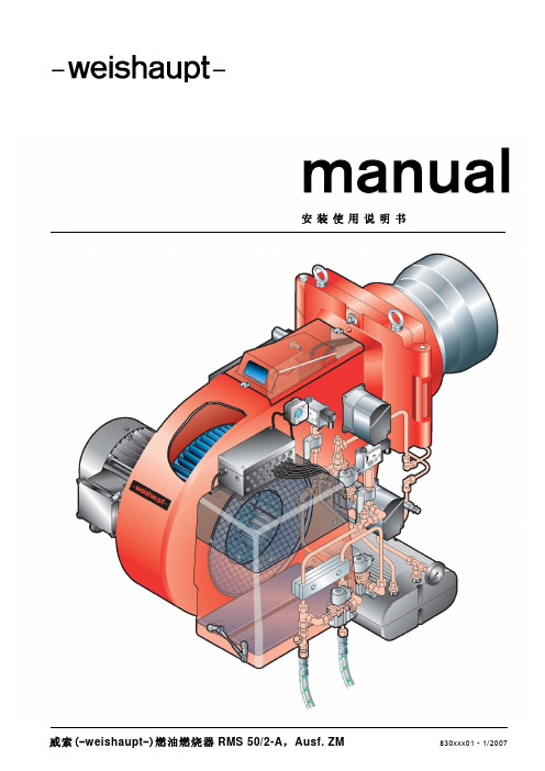
2.1 RMS50 manual (中文)
安装使用说明书威索(-weishaupt-)燃油燃烧器RMS 50/2-A,Ausf. ZM 830xxx01 - 1/200723目 录1 一般说明 52 安全须知 63 技术说明83.1 应用条件 83.2 基本功能 93.3 燃油调节系统 103.4 油泵12 3.4.1 独立泵站 12 3.4.2 一体式油泵 143.5 燃油预热系统153.6 燃烧控制管理器W-FM 的功能164 安装174.1 安装安全须知 174.2 运输及仓储 174.3 安装前的准备 174.4 供油系统 184.5 喷嘴的选择 214.6 燃烧器的安装 224.7 油管连接 244.8 电气线路连接255 调试及操作265.1 调试安全须知 265.2 首次调试前的措施 275.3 W-FM 的操作 285.4 调试及优化 295.5 调试后的措施 315.6 设备停止运行326 故障原因及排除336.1 燃烧器常见故障 336.2 W-FM 的故障3512345647 维护367.1 维护安全须知 367.2 维护工作367.2.1 测试、清洁和功能检查 367.3 混合装置的拆卸及安装 377.4 喷嘴的拆卸与安装 387.5 点火电极的设定 397.6 混合装置的设定和检查 407.7 混合装置伺服机构的拆卸和安装 417.8 风门伺服机构的拆卸和安装 427.9 回油调节器伺服机构的拆卸与安装438 技术数据448.1 燃烧器配置 448.2 工作范围表 448.3 适合的燃料 458.4 混合装置尺寸 458.5 允许的环境温度 468.6 电气数据 468.7 重量 468.8 燃烧器尺寸47附录48烟气分析 4878A1 一般说明本安装使用说明书 y 是设备的重要组成部分,必须始终保存于设备使用处备查;y部分内容在下列安装使用说明书中有所补充: - 燃烧控制管理器W-FM 使用说明书 - 燃油预热器使用说明书 y 只能由合格的专业人士进行指导;y 包含了有关设备安全的重要安装、调试及维护方面的说明;y对所有与设备运行有关人员均应引起注意。
MCR说明

MCR说明MCR调节模式:综合模式:恒电压模式:母线220kV±10%恒无功模式:MCR常见故障:中度过温①、交流380V失电②、电抗器温度确实在70℃以上励磁故障查看故障励磁故障→励磁箱→MCR控制屏→系统状态→励磁状态→A,B,C 项(正常为√)就地故障①、励磁箱供电电源失电1,4AC380V普通励磁5,6AC5250V快速励磁(励磁箱熔断器烧了)。
②轻度过温电抗器油面温度>50℃,散热器风扇没有启动电容器组日常巡视:1、电容器组:送电后,20Min内远离电容器组,防止电容器组爆炸,使用红外成像仪,测量隔离开关接触处,温度是否正常。
2、送电过程中,报不平衡保护动作:①、电容器线圈损坏②、放电线圈损坏③、放电线圈二次接线松动单极隔离开关:正常运行时分闸状态,检修时合闸状态。
检修时,对地放电2min,才能进入电容器框架内。
MCR日常巡视:观察温度表的当前温度。
观察瓦斯继电器观察油位表的位置(储油柜的侧面),对比温度‐油位曲线。
温度高时,注意查看散热风扇运行是否正常。
定期使用红外成像仪,测量母排搭接处温度是否正常。
端子箱检查:液晶控制器;页面显示是否正常,判断端子箱供电是否正常。
MCR本地端子箱作用:1、控制信号的光电转换2、非电量保护信号、电流信号转接(①、过温1。
②、过温2。
③过温3。
④重瓦斯。
⑤轻瓦斯⑥压力释放阀动作,其中重瓦斯、压力释放阀动作作用于35V1K跳闸)。
3、提供供电电源:①、AC380V交流屏②、AC220V小空开电源③、DC220V端子箱继电器。
石油化工常用英文缩写非常的实用

石油化工常用英文缩写非常的实用与大家免费分享,希望能对大家以后的学习工作有一定帮助!序号缩写英文中文1 AC Air Conditioning 空气调节装置2 AGO Atmospheric gas oil 常压瓦斯油3 AML Approved Manufacturers' List 批准的厂商名单4 APE Area Project Engineer 区域项目工程师5 AR Atmospheric residue 常压渣油6 ARDS Atmospheric residue desulfurization 常压渣油加氢脱硫7 ASME American Society of Mechanical Engineers 美国机械工程师协会8 BD Business Director 商务主任9 BD Business Development 市场部10 BEDP Basic Design Engineering Package 基础设计包11 BFW Boiler feed water 锅炉给水12 BL Battery limits 界区13 BEDD Basic Engineering Design Data 基础工程设计数据14 BM Bill of Material 材料表15 BOD Basis of Design 设计基础16 BOD Biological Oxygen Demand 化学需氧量17 BP Boiling point 沸点18 BS Bright stock 光亮油19 BSI British Standards Institute 英国标准协会20 BTEX Benzene, toluene, ethyl benzene, xylene 苯,甲苯,乙苯,二甲苯21 BTU British thermal unit 英热单位22 BTX Benzene, toluene, xylene 苯,甲苯,二甲苯23 C Construction 施工24 CAD Computer Aided Design 计算机辅助设计25 CADD Computer Aided Design and Drafting 计算机辅助设计和绘图26 CCR Conradson carbon residue 康氏残炭27 CCR Continuous Catalyst Regeneration 催化剂连续再生28 CDU Crude distillation unit 原油蒸馏装置29 CGO Coker gas oil 焦化瓦斯油30 CI Cetane index 十六烷指数31 CL Center line 中心线32 CM Construction Manager 施工经理33 CN Conference Note 会议纪要(老外更喜欢用 MOM:Minitues of Meeting)34 COD Chemical oxygen demand 化学需氧量35 CPDP Chinese Preliminary Design Package 中国初步设计包(直接称为 PDP就 OK 了)36 CPM Critical Path Method 关键路径法37 CR Catalytic Reforming 催化重整38 CS Carbon Steel 碳钢39 CW Cooling Water 冷却水40 FEED Front End Engineering Design 前期工程设计41 GB GUO BIAO 国标42 GCD Guaranteed Completion Date 保证完成日期43 GG Gauge glass 玻璃液面计44 GHSV Gaseous hourly space velocity 气体体积空速45 GPH Gas phase hydrogenation 气相加氢46 GSN Global Supply Network 全球供应网络47 GTG Gas Turbine Generator 燃气涡轮发电机48 GW Gross weight 毛重49 HAZID Hazard Identification Review 危险识别审查50 HAZOP Hazard and Operability Study 危险与可操作性研究51 HBP Highly branched paraffins 高支链烷烃52 HC Hydrocracking 加氢裂化53 HCCO Heavy catalytic cycles oil 重催化循环油54 HCGO Heavy coker gas oil 重焦化瓦斯油55 HDA hydrodearomatization 加氢脱芳烃56 HDF hydrofinishing 加氢后精制57 HDM hydrodemetallization 加氢脱金属58 HDN hydrodenitrogenation 加氢脱氮59 HDPE High Density Polyethylene 高密度聚乙烯60 HO Home Office 总部61 HDS hydrodesulfurization 加氢脱硫62 HDT hydrotreating 加氢精制,加氢处理63 HGO Heavy gas oil 重瓦斯油64 HR Human Resource 人力资源65 HP High pressure 高压66 HSFO High sulfur fuel oil 高硫燃料油67 HSR Heavy straight run 重直馏油68 HVAC Heating, Ventilation and Air Conditioning 采暖通风69 HVGO Heavy vacuum gas oil 减压重瓦斯油70 HVI High viscosity index 高粘度指数71 IBL Inside Battery Limits (Same as ISBL) 界区内72 IBP Initial Boiling Point 初馏点,初沸点73 IEC International Electro‐technical Commission 国际电工委员会74 IFA Issued for Approval 用于正式批准75 IFB Issued for Bid 用于招标(ITB:用的更多)76 IFC Issued for Construction 用于施工77 IFD Issued for Design 用于设计78 IFH Issued for HAZOP 用于危险与可操作性研究79 ISBL Inside Battery Limits (same as IBL) 界区内80 ISO International Standardization Organization 国际标准化组织81 IS&T/IT Information System and Technology (same as IT) 信息系统和技术82 ITB Invitation to Bid 邀标书83 JV Joint Venture 合营者84 KW Kilo‐Watt 千瓦85 LAN Local Area Network 局域网86 LC Letter of Credit 信用证 87 LCC Life Cycle Cost 寿命周期成本88 LCCO Light catalytic cycle oil 催化裂化轻循环油89 LCGO Light coker gas oil 焦化轻瓦斯油90 LCN Light coker naphtha 焦化轻汽油91 LCO Light cycle oil 轻循环油92 LDE Lead Discipline Engineer 专业负责人93 LDPE Low Density Polyethylene 低密度聚乙烯94 Level 1 High Level Schedules, control documentsused for control of total scope 项目计划1 (项目进度)95 Level 2 Intermediate Level Schedules, control documents designed to control area, department, contract or discipline level 项目计划 296 Level 3 Detailed Schedules, control documents designed to control and report individual deliverables, e.g. documents, requisitions etc. 项目计划 3(还有 LEVEL 4)97 LLDPE Linear Low Density Polyethylene 线性低密度聚乙烯98 LOI Letter of Intent 意向书99 LP Low Pressure 低气压100 LPG Liquefied Petroleum Gas 液化石油气101 LS Lump Sum 固定总价102 LS Low sulfur 低硫103 LSD Low sulfur diesel 低硫柴油104 LSFO Low sulfur fuel oil 低硫燃料油105 LSR Light straight run 轻直馏油106 LSTK Lump Sum Turn Key (一揽子价格)总承包107 LSWR Low sulfur waxy residue 低硫含蜡渣油108 LTFT Low‐temperature flow test 低温流动性试验109 LTRS Low‐temperature recovery system 低温回收系统110 LV Low Voltage 低(电)压111 LVGO Light vacuum gas oil 轻减压瓦斯油112 LVI Low viscosity index 低粘度指数113 LVN Light virgin naphtha 直馏轻石脑油馏分114 MC Mechanical Completion 机械竣工115 MCR Micro carbon residue 微残炭116 MEG Mono Ethylene Glycol same as EG) 乙二醇117 MHC Mild hydrocracking 缓和加氢裂化118 MPA Multi Project (Purchasing) Agreement 大宗采购协议119 MFA Multi‐Facility (Purchase) Agreement 大宗采购协议120 MON Motor octane number 马达法辛烷值121 MP Medium pressure 中压122 MPHC Moderate pressure hydrocracking 中压加氢裂化123 MR Material Requisition 请购单124 MRP Material Requisition (issued for Purchase) 请购单(用于购买)125 MRQ Material Requisition (issued for Quotation) 请购单(用于报价)126 MRR Material Receiving Report 材料验收单 127 MTO Material Take‐Off 材料表128 MV Medium Voltage 中(电)压129 MW Mega‐Watt 兆瓦130 MW Molecular weight 分子量131 N/A Not applicable or Not Appropriate 不适用的132 N/A Not Available 无133 NEC National Electrical Code 国家电气规范134 NEMA National Electrical Manufacturers Association 国家电气制造商协会135 NFPA National Fire Protection Association 全国防火协会136 NGL Natural Gas Liquids 天然气液体137 NP Normal paraffin 正构烷烃138 NPSH Net positive suction head 净吸入头139 NR Non Reimbursable (costs) 非实报实销140 NTP Notice To Proceed 开工通知书141 NTS Not to Scale 不按比例142 OBL Outside Battery Limits £®same as OSBL 界区外143 OBS Organization Breakdown Structure 组织分解结构144 OSBL Outside Battery Limits (same as OBL) 界区外145 P3 Primavera Project Planner 项目计划管理(一个盛名之下,其实难负的进度编制软件,用来忽悠忽悠老外还行)146 PAC Polycyclic aromatic compound 稠环芳烃,多环芳烃147 PAG Project Automation Group 项目自动化团队148 PAF Personnel Authorization Form 职员批准表149 P&ID Process and instrumentation Diagram 工艺仪表流程图150 PID Proportional, Integral and Differential 比例、积分加微分(控制)151 PC Personal Computer 个人电脑152 PDA Propane deasphalting 丙烷脱沥青153 PDAO Propane deasphalted oil 丙烷脱沥青油154 PDU Propane deasphalting unit 丙烷脱沥青装置155 PE Project Engineer 项目工程师156 PE Polyethylene 聚乙烯157 PEM Project Engineering Manager 项目设计经理158 PET Project Execution Team 项目执行组159 PFD Process Flow Diagram 工艺流程图160 PFE Project Field Engineer 项目现场工程师161 PFPM Project Field Procurement Manager 项目现场采购经理162 PEFS Process Engineering Flow Scheme (same as P&ID) 工艺设计流程图163 PFS Process Flow Scheme (same as PFD‐Process Flow Diagram) 工艺流程图164 P/L Packing List 装箱单165 PM Project Manager 项目经理166 PMC Project Management Contractor 项目管理承包商167 PMM Project Material Manager 项目材料经理168 PNA Polynuclear aromatics 稠环芳烃,多环芳烃169 PNA Paraffin, Naphthene, Aromatic 烷烃、环烷烃、芳烃 170 PO Procurement Order 采171 POX Partial Oxidation 部分氧化造气172 PP Polypropylene 聚丙烯173 PPM Project Procurement Manager 项目采购经理174 PQP Project Quality Plan 项目质量计划175 PQAM Project Quality Assurance Manager 项目质量保证经理176 PQCM Project Quality Control Manager 项目质量控制经理177 PR Procedure 程序178 PRC People Republic of China 中华人民共和国179 PRS Power recovery system 能量回收系统180 PSA Pressure swing adsorption 变压吸附181 PSM Project Site Manager 项目现场经理182 PVC Poly Vinyl Chloride 聚氯乙烯183 PW Paraffin wax 石蜡184 QA Quality Assurance 质量保证185 QC Quality Control 质量控制186 QM Quality Management 质量管理187 RDS Resid desulfurization 渣油(加氢)脱硫188 RFCC Resid FCC 渣油催化裂化189 RFG Reformulated gasoline 新配方汽油190 RHC Resid hydroconversion 渣油加氢转化191 RHDS Residue hydrodesulfurization 渣油加氢脱硫192 RIS Refinery information system 炼油厂信息系统193 RMP Risk management plan 风险管理计划194 RON Research octane number 研究法辛烷值195 RONC Research octane number clear 不加铅研究法辛烷值196 ROSE Resid oil supercritical extraction 渣油超临界抽提197 SCO Synthetic crude oil 合成原油198 SDW Solvent dewaxing 溶剂脱蜡199 SIGF Site Integration & General Facility 全场一体化和一般设施200 RFSU Ready for Start Up 待开车201 S/C Subcontractor 分包商202 SM Styrene Monomer 苯乙烯单体203 SOR Start of run 运转初期204 SR Semi‐regenerative 半再生的205 SR Straight run 直馏206 SRU Sulfur recovery unit 硫磺回收装置207 SS Stainless Steel 不锈钢208 SSOT Single stage once through 一段一次通过加氢裂化209 STG Steam Turbine Generator 蒸汽发电机210 TAN Total acid number 总酸值211 TBD To be Determined 待定212 TBN Total base number 总碱值213 TBS Technical Bid Summary 技术标概要 214 T&C'S Terms and Conditions (e.g. of pur 购)215 TCD Target Completion Date 目标完成日期216 TGCU Tai l gas cleanup unit 尾气净化装置217 TGTU Tai l gas treating unit 尾气处理装置218 TIC Total Installed Cost 总体安装费用219 T&L Traffic and Logistics 交通与后勤管理220 TS Technical Specialist 技术专家221 TSA Technical Services Agreement 技术服务协议222 TF Tank Farm 罐区223 UFD Utility Flow Diagram 公用工程流程图(UP&ID 或 UID更常用)224 ULSD Ultra low sulfur diesel 超低硫柴油225 UK United Kingdom 英国226 UR Unit Rate 单价227 USA United States of America 美利坚合众国228 VDU Vacuum distillation unit 减压蒸馏装置229 VE Value Engineering 价值工程230 VGO Vacuum gas oil 减压瓦斯油231 VI Viscosity index 粘度指数232 VL Vendor List 制造厂表233 VP Vendor Print 厂商资料234 VPMS Vendor Print Management System 厂商资料管理系统235 VPTL Vendor Print Transmittal Letter 厂商资料传送236 VR Vacuum residue 减压渣油237 VRDS Vacuum residue desulfurization 减压渣油加氢脱硫238 VTB Vacuum tower bottoms 减压渣油239 WAN Wide Area Network 广域网240 WHSV Weight hourly space velocity 重时空速241 WPC World Petroleum Congress 世界石油大会242 WT Weight 重量243 WWTS Wastewater treatment system 污水处理系统244 VCM/PVC Vinyl Chloride 氯乙烯/聚氯乙烯245 VIP Value Improvement Practices 价值工程实践246 WBS Work Breakdown Structure 工作分解结构(这个是很重要的衡量进度的手段。
R-50资料
DESCRIPTIONRaeco R-50 is a two component, concrete repair and topping compound consisting of a uniform, premixed blend of portland cements and graded washed silica aggregates with a liquid latex modifier to promote lasting surface adhesion, for renovation and new construction. R-50 can be applied from feathered edge to any depth, for thickness greater than 1/2” (12.7 mm) use appropriate aggregate. R-50 should be used for horizontal surfaces. Suitable for interior and exterior use, a sealer or coating is recommended when used for a wearing surface. R-50 provides excellent freeze-thaw resistance against the penetration of deicing salts and other contaminants. Raeco R-50 contains no gypsum, chlorides, ferrous metals or corrosive agents.PROPERTIES7 Days28 DaysCompressive Strength PSI (ASTM C-1439)47105560Tensile Strength, PSI (ASTM C-190)850Flexural Strength, PSI (ASTM C-256)1700Shear Bond, PSI (Dow Test Method)650+• Flame Spread: 0• Fuel Contribution 0• Smoke Development: 0• Compatible with most floor adhesives • Smooth or broom finish achievable • Horizontal application • Fire Retardant • Non-toxic• Corrosion Resistant • U.S.D.A. approvedAREAS OF USE• Parking deck repairs and overlays • Horizontal & vertical applications• Exterior applications for walkways & ramps • Warehouse & industrial repairs or overlays • Areas exposed to heavy-duty loads • Leveling or creating pitch to drains • Rained out or freeze damaged slabs • Areas with varying weather cycle • Corrosion-resistant overlays PACKAGING• 50 lb. bags (22.5 kg.)• (40 bags per pallet)• 1.2 gallon container (4.55 liters)• 5 gallon pail (18.9 liters)• 50 gallon drum (189.5 liters)APPROXIMATE COVERAGE50 lb. bag: 50 sf (4.64 m 2) @ 1/8” (3.18 mm)Bulked with #8 Silica sand50 lb. bag: 18.75 sq. ft. (1.73 m 2) @ 1/2” (12.7 mm)Bulked with 3/8” pea gravel50 lb. bag: 9.06 sq. ft. (.83 m 2) @ 1” (25.4 mm)For Thickness:1/2” to 1” use #8 silica sand @ 25 lbs. (11.25 kg) per bag 1” & up use 3/8” pea gravel @ 25 lbs. (11.25 kg) per bag The values presented are typical averages and are intended to serve as a guide only.SURFACE PREPARATIONSurfaces to be covered must be structurally sound, clean and free of dust, oil, grease, sealers, curing compounds,laitance, release agents or other surface contaminants. For smooth surfaces, we recommend mechanical abrasion to achieve an ac-ceptable surface profile. The cleaning and preparation method selected depends on both the sub-floor material and its condition. Acid etching is not recommended. For optimum adhesion, mix R-50 with the latex to a slurry consistency and brush thoroughly into the area to be covered. Raeco R-2000 may also be used as a bonding medium. DO NOT USE R-50 LATEX AS A BONDING AGENT.R-50 Latex Mortar OverlaymentProduct Data SheetMIXINGRaeco R-50 is mixed by adding R-50 latex at a rate of approximately 1 gallon (3.79 liters) of latex for each 50 lb. bag of dry powder. More or less latex may be added to obtain the desired consistency, but do not exceed 2 gallons (7.58 liters) of latex for each 50 lb. bag of R-50. The latex should be added to the mixing container first, then the R-50 powder, followed by the appropriate aggregate (when used).Using a mixing paddle (a whip type is recommended) with a low speed drill (400 to 500 rpm), mix thoroughly (2 to 3 minutes) until the powder has been completely dispersed and the mix has acquired a smooth homogeneous texture. Do not add more latex binder once R-50 has started setting up. The pot life of the mix averages about 30 minutes and working time 30 to 45 minutes, depending on the temperature. It is recommended to mix only the amount of R-50 that can be applied within that amount of time.APPLICATIONApply the Raeco R-50 mixture with a trowel or straight edge, trowel to desired texture, on the prepared surface. Should a broom finish be desired, do so after placement. Do not add or spray latex onto the surface for finishing, it may cause the surface to spall. Rough spots or trowel marks may be sanded off the surface, using a medium to fine grit sandpaper after R-50 has setup. Sanding should be accomplished no later than 24 hours after application. Allow an adequate curing time before applying a sealer, by using the R-50 latex or a water based concrete sealer (surface or penetrating). When R-50 is going to be a wearing surface, a sealer or coat-ing is recommended.When R-50 is to be applied on surfaces other than concrete (i.e., wood, metal, terrazzo, gypsum underlayments, etc.), consult Raeco’s Technical Service Department for recommended preparation, bonding, and application procedures.LIMITATIONSRaeco R-50 should only be applied over substrates that are between 40° and 90° F. (4.4° and 32.2° C.) Do not apply in the rain, and do not allow to freeze before curing has taken place. When applying R-50 to thickness greater than 1/2” (12.7 mm), bulk the mix with the appropriate type and amount of aggregate (refer to Coverage section of Data Sheet).WARNINGRaeco R-50 contains portland cement and silica sand. Use of a dust respirator, safety goggles and rubber gloves are recommended. In case of contact with eyes, immediately flush with water and consult a physician. Avoid hazards by following all precautions found in the Material Safety Data Sheet (MSDS), product labels and technical literature. Please read this information prior to using product. WARRANTYRaeco, Inc. warrants that if its products prove to have manufacturing defects and Raeco is notified of such within six months from the date Raeco shipped the products, Raeco will replace the defective products F.O.B. factory. Such product replacement shall constitute the sole and exclusive remedy for any claim under this warranty. Raeco does not authorize anyone, including Raeco Representatives, to make any statements that supersede, modify or supplement the information provided on its printed literature or package labels without written confirmation from the Raeco Technical Service Department. Any installations proceeding without this confirmation, or improper installations of the products will void this warranty. Under no circumstances will Raeco be liable for economics, special, incidental, or consequential damages or losses of any kind whatsoever arising out of or occasioned by selection, use installation or replacement of this product.GUIDE SPECIFICATIONS: Consult Raeco, Inc. for R-50 & Stained R-50 Guide Spec (4 pages) latest edition.Raeco, Inc.915 S. Carstens Place / P.O. Box 80545Seattle, Washington 98108Phone: (206) 763-1335 Toll free: (877) 763-1330Fax: (206) 768-0175 E-mail: info@Website: 。
说明书 - MC50 - 中文版

6 常见故障................................................................................................ 14
4 技术参数................................................................................................ 12
4.1 几何尺寸..................................................................................................................................................... 12
标准描述 电磁兼容性 家用和类似用途电器的安全 电工电子产品应用环境条件-储存 电工电子产品应用环境条件-运输 电工电子产品应用环境条件-使用
MC 系列室外机柜空调器 用户手册
2
深圳市英维克科技股份有限公司
2 安装和操作
2.1 拆除包装和检验
本产品标准采用纸箱包装,拆除包装时,先将包装外部的打包带拆除,打开纸箱上 盖并将纸箱抽出。注意清点包装内的装箱清单和附件包。
2.2 安装前准备
安装前注意: 机柜内部环境设备的摆放,尽量避免与空调器内循环进出风口有阻隔。
2.3 空调器机械安装
空调器机械安装包括如下工作: 空调粘贴密封胶条:
MCR参考手册

CNC系统OSP-P200 OSP-P20参考手册(第7版)出版号SC34-012-R7 July 2009安全注意事项本机床为了预防事故的发生,保证人身和机床的安全,配置了安全装置。
但是,操作员不能只依赖于这些安全装置,还必须仔细阅读和熟练掌握以下的安全注意事项,以保证无事故发生。
本手册以及贴在机床盖板上的危险警告标牌仅限于本社可预见的范围,注意,这不包括所有可能出现的危险。
总之在操作时请切实地注意安全。
1.与安装相关的注意事项(1)请注意以下与主电源相关的注意事项。
•应避免大的电气噪声发生源(电焊机,放电加工设备)和本机床使用同一个配电板,否则会引发NC装置发生故障。
•地线应尽可能单独连接,万不得已的情况下也应避免和电气噪声发生源(电焊机,放电加工设备)共用。
(2)安装环境安装控制柜时,应注意下述事项。
•避免阳光直射NC装置。
•控制柜应不受切屑,水,油等的侵害。
•控制柜和操作面板,不应受到过大的振动和冲击。
•控制柜的允许环境温度范围为5到40°C。
•控制柜的允许环境湿度范围为50%或更低(40°C时)(无凝露)。
•控制柜的海拔为1000m以下。
2.接通电源时的确认事项(1)为了防止水,切屑和灰尘的进入,应关上控制柜和操作面板的门。
(2)在确认机床的运动部件没有人和障碍物的前提下,方可起动机床。
(3)接通电源时,应先打开主电源开关然后再打开操作面板上的加电开关。
3.有关手动和连续运行的注意事项3-1.车床(1)操作过程中,必须遵守使用说明书的要求。
(2)在机床前护盖、卡盘护盖和其它护盖被拆卸的情况下,不得运行机床。
(3)在起动机床之前,应该关闭前护盖。
(4)在加工首件时,请检查机床的运行情况,使机床处于空载运行以对部件之间的干涉进行检查,在单程序段模式下切削工件,然后再起动连续运行。
(5)旋转主轴或机床运动部件之前,请确保自身的安全。
(6)主轴正在旋转时,请不要触摸切屑或工件。
依玛冠军50说明书

1.14 冷凝水虹吸管 ........................................................................................................................................................19
1.15 启动燃气系统 ........................................................................................................................................................19
VICTRIX 50 (冠军 50)
GB
指示及说明手册
安装人员 用户 技术人员
尊敬的客户: 祝贺您选择了意大利依玛股份有限公司 (IMMERGAS S.P.A.) 的产品,意大利依玛股份有限公司 (IMMERGAS S.P.A.) 高质量的产品能够为您带来长期的生活便利和安全。作为意大利依玛股份有限 公司 (IMMERGAS S.P.A.) 的顾客,您可以依赖我们授权的售后服务,这个服务体系专业,训练有素, 能够为您的锅炉持续高效运转提供有力的保障。 仔细阅读本手册的内容,您就能从中获取正确使用所购设备的有用建议,遵守这些建议就能使您从意 大利依玛股份有限公司 (IMMERGAS S.P.A.) 的产品中获得满足感。 请及时同我们的区域售后服务中心联系,提出对初期运转情况进行检查的要求。我们的技术员将会证 实运行状况是否良好,对设备进行必要的调整,向您表述锅炉的正确的使用方法。 如有必要,可要求经意大利依玛股份有限公司 (IMMERGAS S.P.A.) 授权的售后服务中心进行日常维 护,这些这些配备原厂备件,并直接由制造厂商进行过专门的培训。
可控硅MCR参数
可控硅MCR参数可控硅(Silicon Controlled Rectifier,SCR)是一种半导体器件,可通电流方向正向,关断电流方向反向。
它由四个或更多层P-N结组成,具有单向导电性,当控制电压施加在门极上时,可控硅进入导通状态,反之,则进入阻断状态,由此实现电流的控制。
可控硅广泛应用于电力电子领域,如交流电压调速、电磁起动、直流电流调节等。
可控硅的主要参数有:1.封装形式:可控硅可以采用不同的封装形式,如TO-92、TO-126、TO-220等,不同的形式适用于不同的应用场合。
封装形式会影响到可控硅的散热性能和安装方式等。
2. 额定电压(Vdrm):可控硅能够承受的最大正向电压。
超过此电压将会损坏可控硅。
额定电压是选择可控硅时需要考虑的重要参数。
3.额定电流(It):可控硅能够承受的最大正向电流。
超过此电流将会损坏可控硅。
额定电流是选择可控硅时需要考虑的重要参数。
4. 关断速度(didt):可控硅关断的最大速度。
当电流减小得太快时,可控硅可能无法完全关断,导致通电状态。
关断速度越高,可控硅的适用范围就越广。
5. 门极电流(Igt):控制可控硅导通的最小门极电流。
当门极电流超过此值时,可控硅进入导通状态。
门极电流越小,可控硅的控制灵敏度就越高。
6. 阻断电流(Irrm):可控硅在阻断状态下可能存在的泄漏电流。
阻断电流越小,可控硅的关断性能就越好。
7.温度特性:可控硅的性能与温度有关,一般会在数据手册中给出温度特性曲线。
温度特性是选择可控硅时需要考虑的重要参数。
可控硅的参数对于设备的性能和可靠性有重要影响,因此在选择可控硅时应综合考虑不同的参数,并根据具体应用需求进行选择。
同时,在使用可控硅时,也应根据数据手册中的参数,合理设计电路,确保可控硅的正常工作。
REVO 50 用户手册说明书

9 12
11
10
10 Mount the Backdrop (I) to the Backdrop Clamp (H) and position the Backdrop as close as possible to the Top Plate (J).
11 Mount your camera onto the Camera Pole (G).
For more information please visit our website:
Fig. 4
Additional information
Mounting Options: • The Center Shaft (B) can be mounted directly onto a C-Stand as shown in Fig. 5. • The Base Plate (A) features 4 holes for mounting purposes. Screws are not included
At this point, your setup should look like in Fig. 3.
8
6
5
7
Fig. 3
For more information please visit our website:
Assembly
9 Place the Top Plate (J) on the Center Shaft (B).
MC-50说明书
前言感谢您使用江苏金方圆数控机床有限公司生产的MC-50型数控母线冲孔机。
MC-50型数控母线冲孔机是江苏金方圆数控机床有限公司自主开发设计生产的高品质、多功能的新一代数控母排加工机。
在使用MC-50型数控母排加工机之前,请您仔细阅读本手册,以保证正确使用并充分发挥其优越性能。
另外,本手册为随机发送的资料,务必请您使用后妥善保管,以备今后对机床进行检修和维护时使用。
您在没有得到金方圆公司明确的许可前不得随意更改或删除机床的所有参数,不得随意更换和拆除机床上的零部件,由于误操作而导致的机器损坏或意外人身伤害与我公司无关。
当您阅读本手册时,若发现了印刷错误,或有更恰当的建议,以及对内容有任何不解或疑问之处,请与江苏金方圆数控机床有限公司联系。
对于您在使用过程中有任何需要帮助之处,请拨打销售电话0514-********、87873787,售后服务电话0514-********、87882730,传真0514-********。
目录前言 (1)目录 (2)一安全须知 (6)1.1序言 (6)1.2标识 (6)1.3机床安全标识及位置 (8)1.4安全说明 (9)二概述 (13)2.1机器的主要用途和特点 (13)2.2型号命名 (14)2.3机器工作原理 (14)2.4基本参数 (14)三机床主要部件 (16)3.1机器的组成 (16)3.2模具移动(Y轴方向) (17)3.2.1 模具移动装置 (17)3.2.2 原点定位装置 (17)3.2.3 手动压料装置 (18)3.2.4换模装置 (19)3.3冲头移动(Z轴方向) (21)3.4送料部分(X轴方向) (21)3.5推料气缸 (22)3.6压料装置 (22)3.7排屑装置 (23)3.8模具 (24)3.8.1 通用模具结构 (24)3.8.1.1 通用模具的材料 (24)3.8.1.2 通用模具的间隙 (24)3.8.1.3 通用模具的安装注意事项 (25)3.8.2 切断模 (25)3.8.3 压花模 (26)四系统说明 (27)4.1液压系统 (27)4.1.1 概述 (27)4.1.2 液压系统工作原理 (27)4.1.3 液压系统试车前准备工作 (32)4.1.4 液压油使用注意事项 (32)4.1.5 其它注意事项 (32)4.2气动系统 (33)4.2.1 概述 (33)4.2.2 气源处理装置的组成 (34)4.2.3 空气压力的设定 (34)4.2.4 注油 (35)4.2.5 设定滴油量 (35)4.2.6 分水过滤器 (35)4.2.7 使用注意事项 (35)4.2.8 气动系统故障原因及对策 (35)4.3润滑系统 (36)4.3.1 概述 (36)4.3.2 使用注意事项 (37)五运输、开箱、安装、试车 (38)5.1运输 (38)5.2开箱 (38)5.3安装 (38)5.3.1 地基 (38)5.3.2 气源 (40)5.3.3 电源 (40)5.3.4 工作环境要求 (40)5.4 试车 (41)六机器的使用、维护与保养 (42)6.1机床的使用 (42)6.2机床的维护与保养 (43)6.2.1 一般要求 (43)6.2.2 机床的检查 (43)七常见故障及排除方法 (45)7.1Y轴方向定位误差 (45)7.2排屑装置链条的调整 (46)八易损件及附图 (47)一安全须知1.1 序言阅读本部分将有益于操作者对机床的了解以及明确如何按照规定正确使用和操作机床。
物料变更管理制度

1 目的为使本公司物料变更流程化和系统化,使物料变更各个环节受控,同时信息能迅速正确传达到相关部门,以确保各部门及客户能及时获得有效最新相关信息,特制订本制度。
2 范围适用于本公司涉及物料变更的所有作业。
3 定义3.1 MCR:MCR 为英文Material Change Request 的缩写,中文名称为物料变更申请。
3.2 MCN:MCN 为英文Material Change Notice 的缩写,中文名称为物料变更通知。
4 职责4.1正式发出MCN 之前必须进行MCR 和MCR 的验证工作。
4.2各部门可向研发部提交MCR 。
4.3研发部负责MCR 的验证和审核。
4.4质量部负责对MCR 造成的风险评估并确认是否对客户造成影响,并根据变更的内容更新相关品质控制文件。
4.5技术总监负责MCR 、MCN 的核准。
4.6生技部负责根据已审核的MCR 进行MCN 的编制、归档,以及存货档案和BOM 清单的更新。
4.7采购部根据MCN 负责物料采购,满足研发和生产的准确需求。
4.8仓储物流部根据MCN 负责对物料变更的处理,保障生产物料供给及时和准确。
4.9市场部负责确认物料变更后的市场反馈效果。
4.10财务部负责确认物料变更后成本的变化以判断是否存在变更价值。
4.11文控负责物料变更文件资料的保管和传阅。
5 流程图:6 内容6.1 MCR 变更申请6.1.1当基于客户要求、内部产品升级、研发试验、工程试验及降低成本等因素,需要涉及物料变更时,由要求变更部门填写《MCR 物料变更申请单》向研发部申请变更。
6.2变更审核、核准6.2.1 研发部接到《MCR物料变更申请单》后,对变更申请内容的可行性组织审核,时间不超过两个工作日;6.2.2《MCR物料变更申请单》经研发部验证审核通过后,转由生技部编制《MCN物料变更通知单》一并提交各单位会签和技术总监核准,并将《MCR物料变更申请单》、《MCN物料变更通知单》递交文控员归档,加盖受控文件章。
安东帕磁流变电流变仪MCR

1在高达12.5 kV的电场条件下执行流变测量
2 0 °C至200 °C范围内的帕尔贴温度控制
3同心圆筒和平行板测量系统
4带有保护罩、接地测量杯或下板的集成式安全设计
规格
温度范围
0 °C至200 °C
电压范围(直流)
0 kV至12.5 kV
最大电流
1 mA
测量夹具
-同心圆筒,直径17 mm和27 mm
-平行板,直径25 mm和50 mm
2可选实时磁场测量,数据直接传输到流变仪软件中
3可选实时温度测量,数据直接传输到流变仪软件中
4两个温控设备型号,温度分别可达70 °C和170 °C
5用于高剪切速率测量的专利技术TwinGapTM,独家授权安东帕公司使用
规格
温度范围
液体温度控制
20 °C至70 °C
液体/帕尔贴组合温度控制
-10 °C至170 °C
最大磁场
1 T (PP20),1.3 T(TwinGapTM)
平行板测量系统
20 mm直径
TwinGapTM
16 mm直径
电流变模块(ERD)
电流变模块(ERD)与MCR流变仪配合使用,用于在对样品施加电场的情况下进行流变测量。此方法对研究电场对电流变液(ERF)的影响非常有用。电场会改变电流变液的黏度,具体取决于所输入的电压。
磁流变模块(MRD)
磁流变设备(Magneto-Rheological Device,MRD)与MCR流变仪配套使用,可以分析磁场对磁流变液(magnetorheological fluids,MRF)和铁磁流体的影响。可施加最大为1特斯拉的均匀磁场。
特点
1在高达1特斯拉(使用TwinGapTM
mcr 电阻

mcr 电阻
MCR电阻是一种常见的电子元件,用于控制电流的流动。
它的全称是Metal Chip Resistor,即金属片电阻器。
MCR电阻通常由金属片制成,具有小巧、耐高温和稳定的特点,在电子设备中被广泛应用。
MCR电阻的主要作用是限制电流的流动,通过电阻的阻碍作用,使电流得到合适的控制。
在电子电路中,MCR电阻可以根据需要选择不同的阻值,以达到所需要的电流大小。
这种电阻器在电路中起到了“阻挡”电流的作用,使得电流在电路中能够按照设计要求进行流动。
MCR电阻的工作原理是基于欧姆定律,即电流与电压之间的关系。
根据欧姆定律,电流等于电压除以电阻,所以当电阻值增大时,电流就会减小。
MCR电阻的阻值可以通过调整其材料、尺寸和形状等参数来实现,从而实现对电流的精确控制。
除了在电子电路中,MCR电阻还可以用于各种电子设备中。
例如,手机、电视、电脑等电子产品中都使用了大量的MCR电阻。
这些电子设备需要稳定的电流控制,以确保它们的正常运行。
MCR电阻的小巧尺寸和高性能使其成为这些设备中理想的选择。
MCR电阻是一种重要的电子元件,通过控制电流的流动,实现对电子设备的稳定运行。
它在电子电路中起到了重要的作用,被广泛应用于各种电子设备中。
MCR电阻的特点是小巧、耐高温和稳定,可
以根据需要选择不同的阻值,以实现对电流的精确控制。
它的工作原理基于欧姆定律,通过调整阻值来实现对电流的控制。
- 1、下载文档前请自行甄别文档内容的完整性,平台不提供额外的编辑、内容补充、找答案等附加服务。
- 2、"仅部分预览"的文档,不可在线预览部分如存在完整性等问题,可反馈申请退款(可完整预览的文档不适用该条件!)。
- 3、如文档侵犯您的权益,请联系客服反馈,我们会尽快为您处理(人工客服工作时间:9:00-18:30)。
Resistors
Thick film rectangular
MCR50 (5025 size: 1 / 2W)
!Features
1) Made of same material as the general purpose chip resistors (MCR10 / 18).2) Highly reliable chip resistor
Ruthenium oxide dielectric offers superior resistance to the elements.3) Electrodes not corroded by soldering
Both flow and reflow soldering can be used.
4) ROHM resistors have approved ISO-9001 certification. Design and specifications are subject to change without notice. Carefully check the specification sheet supplied with the product before using or ordering it.
!Ratings
0.5W (1 / 2W)
- 55˚C to + 125˚C
200V 400V 400V
at 70˚C
Item
Conditions
Specifications
Rated power
Rated voltage
Operating temperature
Nominal resistance See Table 1.
Max. operating voltage Max. overload voltage
Max. intermittent overload voltage
Power must be derated according to the power derating curve in Figure 1 when ambient temperature exceeds 70˚C .
The voltage rating is calculated by the following equation. If the value obtained exceeds the maximum operating voltage, the voltage rating is equal to the maximum operating voltage.
E: Rated voltage (V)
P: Rated power (W)R: Nominal resistance (Ω)
E = P × R
20406080100
-55070100125
AMBIENT TEMPERATURE (˚C )
P O W E R L O A D (%)
Fig.1
Max. 50m Ω
3A 15A - 55˚C to + 125˚C
Jumper type
Resistance Rated current Peak current Operating temperature
F ( ± 1%)
J ( ± 5%)
10 ≤ R ≤ 330k 10 ≤ R < 100k (E24,96)(E24)(E24)
(E24)(E24)
± 200 ± 2002.2 ≤ R < 10
± 5001.0 ≤ R < 2.2500 ± 350 ± 350
330k < R ≤ 560k (E24,96)
± 100100 ≤ R ≤ 180k Table 1
Resistance tolerance Resistance range
(Ω)Resistance temperature coefficient
(ppm / ˚C )
•Before using components in circuits where they will be exposed to transients such as pulse loads (short-duration, high-level loads), be certain to evaluate the component in the mounted state. In addition, the reliability and performance of this component cannot be guaranteed if it is used with a steady state voltage that is greater than its rated voltage.
Resistors
!Characteristics
Resistors
!External dimensions (Units: mm)
!Packaging
Resistors
!Makeup of the part number
MCR50
JZH
LZH
4,000
10,000
World wide World wide
F
± 1% ± 5%J 10Ω
or more (F class)1Ω or more (J class)
Part No.
Paper tape
Code Packaging
Standard ordering
unit(pcs)
Shipped to Blank
Specify "J" for jumper also.
Nominal resistance
Part No.3-digit or 4-digit IEC coding system
!Dimensions
RESISTANCE (Ω)L E N G T H (m m )
Fig.2 Dimensions (length)
RESISTANCE (Ω)W I D T H (m m )
Fig.3 Dimensions (width)
RESISTANCE (Ω)
T H I C K N E S S (m m )
Fig.4 Dimensions (thickness)
!Electrical characteristics
RESISTANCE (Ω)
D C R
E S I S T A N C E (%)
Fig.5 DC resistance
RESISTANCE (Ω)T E M P E R A T U R E C O E F I C I E N T (p p m /˚C )
Fig.6 Resistance temperature
characteristics
RESISTANCE (Ω)
∆R / R (%)
Fig.7 Short time overload
Resistors
RESISTANCE (Ω)
I N S U L A T I O N R E S I S T A N C E ( ×1010
Ω)
Fig.8 Insulation resistance
RESISTANCE (Ω)∆R / R (%)
Fig.9 Withstand voltage
RESISTANCE (Ω)
∆R / R (%)
Fig.10 Intermittent overload
RESISTANCE (Ω)∆R / R (%)
Fig.11 Terminal strength (bendi-
ngl strength characteristics)
RESISTANCE (Ω)∆R / R (%)
Fig.12 Resistance to soldering heat
RESISTANCE (Ω)
∆R / R (%)
Fig.13 Resistance to dry heat
RESISTANCE (Ω)∆R / R (%)
Fig.14 Endurance (rated load)
RESISTANCE (Ω)∆R / R (%)
Fig.15 Endurance (under load in
damp environment)
RESISTANCE (Ω)
∆R / R (%)
Fig.16 Resistance to humidity
(steady state)
Resistors
RESISTANCE (Ω)
∆R / R (%)
Fig.17 Temperature cycling
RESISTANCE (Ω)
∆R / R (%)
Fig. 18 Resistance to solvents。
