驻马店电信公司FTTH_机械连接插头制作教程
经典插头制作教程

Van den HulAudio and Video Cable/Connector Wiring Diagramsfor DIY purposesSelection Table:Other connector types: Headphones | S Video | Scart | DIN | TuchelOther Connectors (pin designations): qHeadphones:Male Stereo 1/4" (6.3mm) or 3.5mm JackPin:Description: Tip Left channel Ring Right channel Sleeve Ground/shieldAvailable from our accessories range: 1/4" (6.3mm) Jack connectorsNote:A rule of thumb regarding stereo jack plugs:The Right channel is always at the Ring: I.e. R ight = R ing(The plug’s configuration being: Tip, Ring, Sleeve).The sleeve of course is always ground/shield: I.e. S leeve = S hieldThat leaves the Left channel at the Tip.qS Video:MALE connectorsolder side view Pin:Description:1Ground (Y)2Ground (C)3Y (Luminance = intensity + Sync.)4 C (Chrominance = color)Available from our accessories range:S-VHS video connectorsSCART adapterAvailable from our A/V cable range:The S-VHS-2-75 video cable q ScartOlder Audio Connector types (pin designations):q DINq Tuchel (microphone connections):Large Tuchel(DIN 41624)Solder side view Pin:Description:1Signal +2Signal –3GroundSmall Tuchel(DIN 41524)Solder side viewPin:Description:1Signal +2Ground3Signal –Van den HulAudio Cable/Connector Wiring DiagramsFemale BalancedXLR ¡TO¡Male BalancedXLRDrawn for line level connections; See remarks below.Remarks:If the cable is to be used for microphone or non mains powered musical instrument connections, i.e. with low (non line level) signals, the cable shield should also be linked to the signal sending side connector’s ground pin.There are two reasons for this:1. To extend the shielding function to the microphone or instrument’s housing.2. And also with phantom powered condenser microphones: To provide a phantom power supply currentreturn path.In all other cases (i.e. line level connections) leaving the cable shield disconnected at one side of the cable (drawn above) is safe practice. This to avoid ground loops with non properly internally grounded equipment.If with these “one side disconnected shield” connections RF interference problems are experienced,reconnecting the shield at the side where it was disconnected by means of a series network of a 47 Ohmresistor and a 10 nanoFarad ceramic disc capacitor is advised. Latter may be standardly applied for all balanced line level interconnections.Reference: K.R. Fause. Fundamentals of Grounding, Shielding and Interconnection. Journal of the Audio Engineering Society, Vol. 43, No. 6, June 1995, p. 498-516.Note: Van den Hul ready made balanced cables standardly have the cable shield connected at both endsallowing correct functionality with microphones and electrical instruments as well as with line level audio and AES/EBU digital connections, latter two assuming properly grounded equipment.Suitable Van den Hul audio cable types and connectors:q Whatever your application, Van den Hul’s broad cable program has the right cable.q Available from our accessories range:r XLR connectorsConnector notes:q XLR connectors have the following pin designations:Pin 2 = Signal +Pin 3 = Signal –Pin 1 = Groundq For optimal contact care we recommend our The SOLUTION contact fluid.Van den HulAudio Cable/Connector Wiring DiagramsFemale BalancedXLR ¡TO¡Male UnbalancedRCAFig. 1: If the signal source is equipped with a pseudo balanced output stage:(See remarks below).Fig. 2: If the signal source is equipped with a cross coupled output stage:(See remarks below).Fig. 3: If the signal source is equipped with an output transformer:(See remarks below).Remarks:In wiring a balanced signal source to an unbalanced input, knowing your exact type of balanced output is important. Your equipment’s documentation or its supplier should be able provide the answer.Balanced outputs come in different flavours; On the one hand there are the true balanced transformer outputs which are completely galvanically isolated and therefore are the least problematic. On the other hand there are the so-called “transformerless” - also named “electronically balanced” - outputs which nowadays are common on most professional equipment. These transformerless/electronically balanced outputs come in two types:1. Quite commonly seen is the plain “pseudo balanced” phase/antiphase output, where the equipment’sinternal unbalanced signal is simply fed to signal + out (XLR pin 2) by means of an opamp buffer and isfed to signal – out (XLR pin 3) simply by means of a polarity inverting opamp. This doesn’t implement atrue balanced output and rather can be looked upon as a pair of unbalanced outputs, one being polarityinverted. Here the above Fig. 1’s wiring configuration is recommended.2. Much more sophisticated is the so-called “cross coupled output stage” in which two cross coupled opampsmimic an output transformer. Here the above Fig. 2’s wiring configuration is recommended.Regarding Fig. 2 and Fig. 3:In case of RF interference, connecting the cable shield to signal ground at the unbalanced signal receiving side’s connector through a 10 nanoFarad ceramic disc capacitor will often solve the problem.Note: Mixed interconnection of electronically balanced and unbalanced equipment remains prone to hum and noise problems since these two types of signal operation are incompatible. The above provides therecommended simple solutions, though, when problems remain in coupling an electronically balanced output to unbalanced inputs, best is to apply an audio isolation transformer.Suitable Van den Hul audio cable types and connectors:q Whatever your application, Van den Hul’s broad cable program has the right cable.q Available from our accessories range:r XLR connectorsr RCA type connectorsConnector notes:q XLR connectors have the following pin designations:Pin 2 = Signal +Pin 3 = Signal –Pin 1 = Groundq RCA type connectors:The Right channel is always color coded Red. (Rule of thumb: R ight = R ed).The Left channel’s plug is generally colour coded Blue, Black or White.q For optimal contact care we recommend our The SOLUTION contact fluid.Van den HulAudio Cable/Connector Wiring DiagramsFemale BalancedXLR ¡TO¡Male Balanced 1/4" (6.3mm)or 3.5mm JackDrawn for line level connections; See remarks below.Remarks:If the cable is to be used for microphone or non mains powered musical instrument connections, i.e. with low (non line level) signals, the cable shield should also be linked to the signal sending side connector’s ground pin.There are two reasons for this:1. To extend the shielding function to the microphone or instrument’s housing.2. And also with phantom powered condenser microphones: To provide a phantom power supply currentreturn path.In all other cases (i.e. line level connections) leaving the cable shield disconnected at one side of the cable (drawn above) is safe practice. This to avoid ground loops with non properly internally grounded equipment.If with these “one side disconnected shield” connections RF interference problems are experienced,reconnecting the shield at the side where it was disconnected by means of a series network of a 47 Ohmresistor and a 10 nanoFarad ceramic disc capacitor is advised. Latter may be standardly applied for all balanced line level interconnections.Reference: K.R. Fause. Fundamentals of Grounding, Shielding and Interconnection. Journal of the Audio Engineering Society, Vol. 43, No. 6, June 1995, p. 498-516.Note: Van den Hul ready made balanced cables standardly have the cable shield connected at both endsallowing correct functionality with microphones and electrical instruments as well as with line level audio and AES/EBU digital connections, latter two assuming properly grounded equipment.Suitable Van den Hul audio cable types and connectors:q Whatever your application, Van den Hul’s broad cable program has the right cable.q Available from our accessories range:r XLR connectorsr1/4" (6.3mm) Jack connectorsConnector notes:q XLR connectors have the following pin designations:Pin 2 = Signal +Pin 3 = Signal –Pin 1 = Groundq Balanced jack plugs have the following pin designations:Tip = Signal +Ring = Signal –Sleeve = Groundq For optimal contact care we recommend our The SOLUTION contact fluid.Van den HulAudio Cable/Connector Wiring DiagramsFemale BalancedXLR ¡TO¡Male Unbalanced 1/4" (6.3mm)or 3.5mm JackFig. 1: If the signal source is equipped with a pseudo balanced output stage:(See remarks below).Fig. 2: If the signal source is equipped with a cross coupled output stage:(See remarks below).Fig. 3: If the signal source is equipped with an output transformer:(See remarks below).Remarks:In wiring a balanced signal source to an unbalanced input, knowing your exact type of balanced output is important. Your equipment’s documentation or its supplier should be able provide the answer.Balanced outputs come in different flavours; On the one hand there are the true balanced transformer outputs which are completely galvanically isolated and therefore are the least problematic. On the other hand there are the so-called “transformerless” - also named “electronically balanced” - outputs which nowadays are common on most professional equipment. These transformerless/electronically balanced outputs come in two types:1. Quite commonly seen is the plain “pseudo balanced” phase/antiphase output, where the equipment’sinternal unbalanced signal is simply fed to signal + out (XLR pin 2) by means of an opamp buffer and isfed to signal – out (XLR pin 3) simply by means of a polarity inverting opamp. This doesn’t implement atrue balanced output and rather can be looked upon as a pair of unbalanced outputs, one being polarityinverted. Here the above Fig. 1’s wiring configuration is recommended.2. Much more sophisticated is the so-called “cross coupled output stage” in which two cross coupled opampsmimic an output transformer. Here the above Fig. 2’s wiring configuration is recommended.Regarding Fig. 2 and Fig. 3:In case of RF interference, connecting the cable shield to signal ground at the unbalanced signal receiving side’s connector through a 10 nanoFarad ceramic disc capacitor will often solve the problem.Note: Mixed interconnection of electronically balanced and unbalanced equipment remains prone to hum and noise problems since these two types of signal operation are incompatible. The above provides therecommended simple solutions, though, when problems remain in coupling an electronically balanced output to unbalanced inputs, best is to apply an audio isolation transformer.Suitable Van den Hul audio cable types and connectors:q Whatever your application, Van den Hul’s broad cable program has the right cable.q Available from our accessories range:r XLR connectorsr1/4" (6.3mm) Jack connectorsConnector notes:q XLR connectors have the following pin designations:Pin 2 = Signal +Pin 3 = Signal –Pin 1 = Groundq For optimal contact care we recommend our The SOLUTION contact fluid.Van den HulAudio Cable/Connector Wiring DiagramsMale UnbalancedRCA ¡TO¡Male BalancedXLRRemarks:The above drawn configuration is recommended. However, with the nowadays common electronically balanced(i.e. non-transformer) inputs, in some cases hum and or RF interference problems can be experienced. In thiscase the cable shield can be experimentally connected to signal ground at the unbalanced signal source side plug, either directly (in case of hum) or (in case of RF interference) by means of a 10 nanoFarad ceramic disc capacitor or a series network of a 47 Ohm resistor and a 10 nanoFarad ceramic disc capacitor. The best solution is situation dependent.Note: Mixed interconnection of balanced and unbalanced equipment remains prone to hum and noise problems since these two types of signal operation are incompatible. The above diagram is the recommended simple solution, though best is to apply an audio isolation transformer when connecting balanced to unbalanced or vice versa.Suitable Van den Hul audio cable types and connectors:q Whatever your application, Van den Hul’s broad cable program has the right cable.q Available from our accessories range:r XLR connectorsr RCA type connectorsConnector notes:q XLR connectors have the following pin designations:Pin 2 = Signal +Pin 3 = Signal –Pin 1 = Groundq RCA type connectors:The Right channel is always color coded Red. (Rule of thumb: R ight = R ed).The Left channel’s plug is generally colour coded Blue, Black or White.q For optimal contact care we recommend our The SOLUTION contact fluid.Van den HulAudio Cable/Connector Wiring DiagramsMale UnbalancedRCA ¡TO¡Male UnbalancedRCAUsing shielded single core cable:Using shielded twin core cable:Using shielded twin core cable is recommended:In this situation the audio signal ground is carried by a dedicated line, which signal current, being separated from the shield, can not easily be interfered with by the shield’s noise currents caused by external interference.This advantage especially counts when low (e.g. microphone) signal levels are being transferred and/or long cable lengths are used. (With shielded single core cable on the other hand, the noise signal built up across the shield effectively is in series with (i.e. adds up to) the audio signal).Furthermore, in connecting the shield to ground only at one side of the cable and lifting it at the other side it functions as a true screen: It does not carry any audio signal; It screens the inner conductors and drains away unwanted noise to one location.Suitable Van den Hul audio cable types and connectors:q Whatever your application, Van den Hul’s broad cable program has the right cable.q Available from our accessories range:r RCA type connectorsConnector notes:q RCA type connectors:The Right channel is always color coded Red. (Rule of thumb: R ight = R ed).The Left channel’s plug is generally colour coded Blue, Black or White.q For optimal contact care we recommend our The SOLUTION contact fluid.Van den HulAudio Cable/Connector Wiring DiagramsMale UnbalancedRCA ¡TO¡Male Balanced 1/4" (6.3mm)or 3.5mm JackRemarks:The above drawn configuration is recommended. However, with the nowadays common electronically balanced(i.e. non-transformer) inputs, in some cases hum and or RF interference problems can be experienced. In thiscase the cable shield can be experimentally connected to signal ground at the unbalanced signal source side plug, either directly (in case of hum) or (in case of RF interference) by means of a 10 nanoFarad ceramic disc capacitor or a series network of a 47 Ohm resistor and a 10 nanoFarad ceramic disc capacitor. The best solution is situation dependent.Note: Mixed interconnection of balanced and unbalanced equipment remains prone to hum and noise problems since these two types of signal operation are incompatible. The above diagram is the recommended simple solution, though best is to apply an audio isolation transformer when connecting balanced to unbalanced or vice versa.Suitable Van den Hul audio cable types and connectors:q Whatever your application, Van den Hul’s broad cable program has the right cable.q Available from our accessories range:r RCA type connectorsr1/4" (6.3mm) Jack connectorsConnector notes:q RCA type connectors:The Right channel is always color coded Red. (Rule of thumb: R ight = R ed).The Left channel’s plug is generally colour coded Blue, Black or White.q Balanced jack plugs have the following pin designations:Tip = Signal +Ring = Signal –Sleeve = Groundq For optimal contact care we recommend our The SOLUTION contact fluid.Van den HulAudio Cable/Connector Wiring Diagrams2 xMale UnbalancedRCA ¡TO¡Male Stereo 1/4" (6.3mm)or 3.5mm JackUsing shielded single core cable:Using shielded twin core cable:Using shielded twin core cable is recommended:In this situation the audio signal ground is carried by a dedicated line, which signal current, being separated from the shield, can not easily be interfered with by the shield’s noise currents caused by external interference.This advantage especially counts when low (e.g. microphone) signal levels are being transferred and/or long cable lengths are used. (With shielded single core cable on the other hand, the noise signal built up across the shield effectively is in series with (i.e. adds up to) the audio signal).Furthermore, in connecting the shield to ground only at one side of the cable and lifting it at the other side it functions as a true screen: It does not carry any audio signal; It screens the inner conductors and drains away unwanted noise to one location.Suitable Van den Hul audio cable types and connectors:q Whatever your application, Van den Hul’s broad cable program has the right cable.q Available from our accessories range:r RCA type connectorsr1/4" (6.3mm) Jack connectorsConnector notes:q RCA type connectors:The Right channel is always color coded Red. (Rule of thumb: R ight = R ed).The Left channel’s plug is generally colour coded Blue, Black or White.q Stereo jack plugs; A rule of thumb:The Right channel is always at the Ring: I.e. R ight = R ing (The plug’s configuration being: Tip, Ring, Sleeve).The sleeve of course is always ground/shield: I.e. S leeve = S hield.That leaves the Left channel at the Tip.q For optimal contact care we recommend our The SOLUTION contact fluid.Van den HulAudio Cable/Connector Wiring DiagramsMale UnbalancedRCA ¡TO¡Male Unbalanced 1/4" (6.3mm)or 3.5mm JackUsing shielded single core cable:Using shielded twin core cable:Using shielded twin core cable is recommended:In this situation the audio signal ground is carried by a dedicated line, which signal current, being separated from the shield, can not easily be interfered with by the shield’s noise currents caused by external interference.This advantage especially counts when low (e.g. microphone) signal levels are being transferred and/or long cable lengths are used. (With shielded single core cable on the other hand, the noise signal built up across the shield effectively is in series with (i.e. adds up to) the audio signal).Furthermore, in connecting the shield to ground only at one side of the cable and lifting it at the other side it functions as a true screen: It does not carry any audio signal; It screens the inner conductors and drains away unwanted noise to one location.Suitable Van den Hul audio cable types and connectors:q Whatever your application, Van den Hul’s broad cable program has the right cable.q Available from our accessories range:r RCA type connectorsr1/4" (6.3mm) Jack connectorsConnector notes:q RCA type connectors:The Right channel is always color coded Red. (Rule of thumb: R ight = R ed).The Left channel’s plug is generally colour coded Blue, Black or White. q For optimal contact care we recommend our The SOLUTION contact fluid.Van den HulAudio Cable/Connector Wiring DiagramsMale Balanced 1/4" (6.3mm) or 3.5mm Jack ¡TO¡Male BalancedXLRDrawn for line level connections; See remarks below.Remarks:If the cable is to be used for microphone or non mains powered musical instrument connections, i.e. with low (non line level) signals, the cable shield should also be linked to the signal sending side connector’s ground pin.There are two reasons for this:1. To extend the shielding function to the microphone or instrument’s housing.2. And also with phantom powered condenser microphones: To provide a phantom power supply currentreturn path.In all other cases (i.e. line level connections) leaving the cable shield disconnected at one side of the cable (drawn above) is safe practice. This to avoid ground loops with non properly internally grounded equipment.If with these “one side disconnected shield” connections RF interference problems are experienced,reconnecting the shield at the side where it was disconnected by means of a series network of a 47 Ohmresistor and a 10 nanoFarad ceramic disc capacitor is advised. Latter may be standardly applied for all balanced line level interconnections.Reference: K.R. Fause. Fundamentals of Grounding, Shielding and Interconnection. Journal of the Audio Engineering Society, Vol. 43, No. 6, June 1995, p. 498-516.Note: Van den Hul ready made balanced cables standardly have the cable shield connected at both endsallowing correct functionality with microphones and electrical instruments as well as with line level audio and AES/EBU digital connections, latter two assuming properly grounded equipment.Suitable Van den Hul audio cable types and connectors:q Whatever your application, Van den Hul’s broad cable program has the right cable.q Available from our accessories range:r XLR connectorsr1/4" (6.3mm) Jack connectorsConnector notes:q XLR connectors have the following pin designations:Pin 2 = Signal +Pin 3 = Signal –Pin 1 = Groundq Balanced jack plugs have the following pin designations:Tip = Signal +Ring = Signal –Sleeve = Groundq For optimal contact care we recommend our The SOLUTION contact fluid.Van den HulAudio Cable/Connector Wiring DiagramsMale Balanced 1/4" (6.3mm) or 3.5mm Jack ¡TO¡Male UnbalancedRCAFig. 1: If the signal source is equipped with a pseudo balanced output stage:(See remarks below).Fig. 2: If the signal source is equipped with a cross coupled output stage:(See remarks below).Fig. 3: If the signal source is equipped with an output transformer:(See remarks below).Remarks:In wiring a balanced signal source to an unbalanced input, knowing your exact type of balanced output is important. Your equipment’s documentation or its supplier should be able provide the answer.Balanced outputs come in different flavours; On the one hand there are the true balanced transformer outputs which are completely galvanically isolated and therefore are the least problematic. On the other hand there are the so-called “transformerless” - also named “electronically balanced” - outputs which nowadays are common on most professional equipment. These transformerless/electronically balanced outputs come in two types:1. Quite commonly seen is the plain “pseudo balanced” phase/antiphase output, where the equipment’sinternal unbalanced signal is simply fed to signal + out (XLR pin 2) by means of an opamp buffer and isfed to signal – out (XLR pin 3) simply by means of a polarity inverting opamp. This doesn’t implement atrue balanced output and rather can be looked upon as a pair of unbalanced outputs, one being polarityinverted. Here the above Fig. 1’s wiring configuration is recommended.2. Much more sophisticated is the so-called “cross coupled output stage” in which two cross coupled opampsmimic an output transformer. Here the above Fig. 2’s wiring configuration is recommended.Regarding Fig. 2 and Fig. 3:In case of RF interference, connecting the cable shield to signal ground at the unbalanced signal receiving side’s connector through a 10 nanoFarad ceramic disc capacitor will often solve the problem.Note: Mixed interconnection of electronically balanced and unbalanced equipment remains prone to hum and noise problems since these two types of signal operation are incompatible. The above provides therecommended simple solutions, though, when problems remain in coupling an electronically balanced output to unbalanced inputs, best is to apply an audio isolation transformer.Suitable Van den Hul audio cable types and connectors:q Whatever your application, Van den Hul’s broad cable program has the right cable.q Available from our accessories range:r RCA type connectorsr1/4" (6.3mm) Jack connectorsConnector notes:q RCA type connectors:The Right channel is always color coded Red. (Rule of thumb: R ight = R ed).The Left channel’s plug is generally colour coded Blue, Black or White.q Balanced jack plugs have the following pin designations:Tip = Signal +Ring = Signal –Sleeve = Groundq For optimal contact care we recommend our The SOLUTION contact fluid.Van den HulAudio Cable/Connector Wiring DiagramsMale Stereo 1/4" (6.3mm) or 3.5mm Jack ¡TO¡2 xMale UnbalancedRCAUsing shielded single core cable:Using shielded twin core cable:Using shielded twin core cable is recommended:In this situation the audio signal ground is carried by a dedicated line, which signal current, being separated from the shield, can not easily be interfered with by the shield’s noise currents caused by external interference.This advantage especially counts when low (e.g. microphone) signal levels are being transferred and/or long cable lengths are used. (With shielded single core cable on the other hand, the noise signal built up across the shield effectively is in series with (i.e. adds up to) the audio signal).Furthermore, in connecting the shield to ground only at one side of the cable and lifting it at the other side it functions as a true screen: It does not carry any audio signal; It screens the inner conductors and drains away unwanted noise to one location.Suitable Van den Hul audio cable types and connectors:q Whatever your application, Van den Hul’s broad cable program has the right cable.q Available from our accessories range:r RCA type connectorsr1/4" (6.3mm) Jack connectorsConnector notes:q RCA type connectors:The Right channel is always color coded Red. (Rule of thumb: R ight = R ed).The Left channel’s plug is generally colour coded Blue, Black or White.q Stereo jack plugs; A rule of thumb:The Right channel is always at the Ring: I.e. R ight = R ing (The plug’s configuration being: Tip, Ring, Sleeve).The sleeve of course is always ground/shield: I.e. S leeve = S hield.That leaves the Left channel at the Tip.q For optimal contact care we recommend our The SOLUTION contact fluid.Van den HulAudio Cable/Connector Wiring DiagramsMale Balanced 1/4" (6.3mm) or 3.5mm Jack ¡TO¡Male Balanced 1/4" (6.3mm)or 3.5mm JackDrawn for line level connections; See remarks below.Remarks:If the cable is to be used for microphone or non mains powered musical instrument connections, i.e. with low (non line level) signals, the cable shield should also be linked to the signal sending side connector’s ground pin.There are two reasons for this:1. To extend the shielding function to the microphone or instrument’s housing.2. And also with phantom powered condenser microphones: To provide a phantom power supply currentreturn path.In all other cases (i.e. line level connections) leaving the cable shield disconnected at one side of the cable (drawn above) is safe practice. This to avoid ground loops with non properly internally grounded equipment.If with these “one side disconnected shield” connections RF interference problems are experienced,reconnecting the shield at the side where it was disconnected by means of a series network of a 47 Ohmresistor and a 10 nanoFarad ceramic disc capacitor is advised. Latter may be standardly applied for all balanced line level interconnections.Reference: K.R. Fause. Fundamentals of Grounding, Shielding and Interconnection. Journal of the Audio Engineering Society, Vol. 43, No. 6, June 1995, p. 498-516.Note: Van den Hul ready made balanced cables standardly have the cable shield connected at both endsallowing correct functionality with microphones and electrical instruments as well as with line level audio and AES/EBU digital connections, latter two assuming properly grounded equipment.Suitable Van den Hul audio cable types and connectors:q Whatever your application, Van den Hul’s broad cable program has the right cable.q Available from our accessories range:r1/4" (6.3mm) Jack connectorsConnector notes:q Balanced jack plugs have the following pin designations:Tip = Signal +Ring = Signal –Sleeve = Groundq For optimal contact care we recommend our The SOLUTION contact fluid.。
2023年电信装维技能竞赛中高级考试模拟试卷

竞赛提高考试模拟试卷(装维)考试说明:提高考试试卷分为试卷一和试卷二两部分,满分为130分,考试时长为90分钟。
其中试卷一满分为100分,考试时长为60分钟;试卷二满分为30分,考试时长为30分钟。
考生在规定期间内提交试卷一后,进行试卷二的答卷。
试卷一考试时长:60分钟一、单选题(共45分,每题1.5分)1、EPON上下行数据分别采用不同的波长进行传输,其中CATV信号采用的波长为(D )。
A-1300nmB-1310nmC-1490nmD-1550nm2、EPON提供的各种业务中,优先级最高的是(A )。
A-语音B-视频C-宽带D-以上优先级相等3、(B )为OLT与ONU之间提供光传输手段,其重要功能是完毕光信号功率的分派任务。
A-OLTB-ODNC-ONUD-ONT4、(C )是指将光网络单元安装在住家用户或公司用户处,是光接入系列中除FTTD(光纤到桌面)外最靠近用户的光接入网应用类型。
A-FTTOB-FTTBC-FTTHD-FTTCab5、E8-B MODEM有多个端口,其中(B )端口是预留给开通ITV业务时使用的。
A-LAN1B-LAN2C-LAN3D-LAN46、EPON(LAN)用户新装宽带时,入户的8芯网线需要用到的分别是(C )。
A-1、2、3、4芯B-5、6、7、8芯C-1、2、3、6芯D-1、2、5、6芯7、ONU的PON口尾纤类型为( C )。
A-FCB-LCC-SCD-ST8、蝶形引入光缆全程标签黏贴不少于两张:在光分派箱和用户终端侧分别黏贴,标签粘贴在距接线器(C )处。
A-2cmB-3cmC-5cmD-10cm9、资源具有装移机条件的,必须满足客户在预约(B )小时后的任一时间(晚20:00-次日8:00 除外)提供上门装机服务A-48B-24C-12D-6010、如桥架内无空间安装波纹管,则应采用(B )对敷设在内的蝶形引入光缆进行包扎,以起到对光缆的保护作用A-过路盒B-缠绕管C-入户暗管D-防水胶布11、ADSL 2+的上行/下行最大速率为(D )。
制作光纤接头的方法

制作光纤接头的方法光纤接头是将两根不同光纤连接起来的一种器件,其作用就是使光信号能够在不同的光纤之间传输。
若想正常传输这些信号,需要精确制作一组良好的光纤接头。
本篇文章将为您介绍制作光纤接头的方法,让你更好地了解到这方面的知识。
一、制作光纤接头的材料在开始制作光纤接头前,需要准备一些材料,其中包括:1、直径为125um的光纤;2、两个光纤接头的壳体;3、丝印墨盒和橡胶小块;4、磨片和亚克力工作台等。
二、制作光纤接头的步骤1、剥离光纤的涂层首先,需要在光纤的外部慢慢剥离其涂层,露出约0.5 cm的纤芯。
这一步需要小心翼翼地进行,以免造成光纤损伤,影响接头的质量。
2、整理和清洁纤芯接着,需要检查和整理纤芯,确保其不携带任何的灰尘和污渍等不良物质。
可以用镊子或者胶带等工具,将纤芯处的杂质清理干净。
3、用橡皮垫在亚克力工作台上放置光纤将光纤垂直地放在橡皮垫上,在亚克力工作台上进行下一步的操作。
4、磨削纤芯端面现在需要用磨片轻轻磨削整理纤芯,直到其端面变得平滑有光泽。
实际上,如果使用的磨片较好,端面应该形成圆弧型,从而减少外部线路的干扰。
5、通过显微镜检查纤芯在本步骤中,需要使用显微镜来检查并评估被磨削过的纤芯。
显微镜可帮助检查纤芯的位置和质量,并保证其最佳性能。
如果纤芯表面发现任何缺陷,需要重复上述磨削操作,并再次进行检查。
6、在光纤接头壳体中安装纤芯接下来,将已经加工完毕的光纤插入到光纤接头壳体中,一方接头以此处理。
7、检查接头的垂直度在最后一步,需要再次使用显微镜检查接头的垂直度。
如果确保接头是垂直的,你就可以把另一根光纤插入到另一个端口,并将其在接头内固定。
通过上述步骤,完成了光纤接头的制作过程。
三、结语制作光纤接头是一项精密而偏重细节和精度的工序。
在制作过程中需要保持专注和耐心,我们在接口质量上会有明显的提升。
通过这篇文章,相信你已经更好地了解了制作光纤接头的方法,可以在实际操作中更加流畅地完成相关工作。
FTTx 中继2M接头制作实训20120301
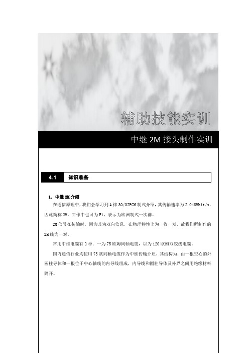
1.中继2M 介绍在通信原理中,我们会学习到A 律30/32PCM 制式介绍,其传输速率为2.048Mbit/s ,因此简称2M 。
工作中也可为E1,表示为欧洲制式一次群。
2M 信号在传输时,因为其为双向信息,在物理特性上为一收一发,故我们所制作的2M 线为一对。
常用中继电缆有2种:一为75欧姆同轴电缆,以为120欧姆双绞线电缆。
国内通信行业均使用75欧同轴电缆作为中继传输介质,其结构为:由一根空心的外圆柱导体和一根位于中心轴线的内导线组成,内导线和圆柱导体及外界之间用绝缘材料隔开。
中继2M 接头制作实训知识准备4.1图1 同轴中继线图例图2 同轴中继接头内部结构2.中继连接器介绍(1)2M接头-L9公头(2)2M头-L9母头用途:用于电信及通信设备(3)2M接头-L9双通(4)2M头-L9三通用途:DDF等连接使用用途:2M自环、DDF侧连通使用。
(5)2M线接头-L9弯头(6)SMA连接器用途:电信及通信设备(7)全铜BNC接头(8)全铜BNC接头(Q9头)用途:视频及仪器仪表等接入场合使用3.中继连接器工具仪表介绍(1)冷压钳日常称为压线钳,有多线径孔位,用于中继接头的压接等场合。
(2)电烙铁一般有恒温、防静电等要求。
在本实训项目中主要是用于中继接头压接之后的焊接工序。
(3)万用表万用表在本实训中主要用到“通断”功能,检测芯线是否焊接正确,检测芯线和皮线是否有短路现象等。
(4)焊锡丝:配套电烙铁使用,用于焊接2M 接头。
(5)剥线钳:剥线钳为内线电工,电动机修理、仪器仪表电工常用的工具之一,其外形如下图。
它是由刀口、压线口和钳柄组成。
在本实训中用于剥除2M 线缆的外层。
(6)斜口钳:斜口钳主要用于剪切导线,元器件多余的引线,还常用来代替一般剪刀剪切绝缘套管、尼龙扎线卡等。
在本实训中用于剪切屏蔽层多余铜线等。
训练目的通过该实训项目实训,学生能够: (1)掌握2M 接头的组成结构和应用环境(2)掌握2M 接头的制作方法4.2 实训目的(3)掌握2M 接头的测试方法(1)制作2M 接头(2)制作BNC 接头 (3)测试2M 接头 (4)测试BNC 接头(1)2M 线若干(2)2M 头(L9/BNC)若干(3)压线钳一把、斜口钳一把、剥线钳一把(每组) (4)电烙铁、焊锡丝若干。
机械式光纤接续技术在光纤到户中(FTTH)的应用

机械式光纤接续技术在光纤到户中(FTTH)的应用.机械式光纤接续技术在光纤到户中(FTTH)的应用. .[字体:大中小在光纤接续领域,机械式光纤接续和熔接接续是实现光纤固定连接的两种不同方式。
机械式光纤接续俗称为光纤冷接,是指不需要熔接机,只通过简单的接续工具、利用机械连接技术实现单芯或多芯光纤永久连接的方式。
本文将重点介绍机械式光纤接续技术在光纤到户(FTTH)中的应用优势。
机械式光纤接续所采用的机械式光纤接续子,又称为光纤冷接子。
不同厂家由于设计结构和所采用的核心技术不同,性能和操作方式有很大的区别。
在选择机械式光纤接续子时,所要评估的方面应主要包括:工具的投资及其维护需求、工具的简单及轻便性、安装的便利性、光纤对准器件的可靠性和夹持力(直接影响接续衰减的大小)、对环境的适应性、是否有耗材、及长期使用稳定性等等方面。
机械式光纤接续技术本身并不是一个新兴的技术,早在20年以前就已经有产品诞生,是一个成熟的光纤接续技术,在美国和日本的数据和图像传输中有较多应用。
光纤机械接续技术在国内1990年以后一直被应用在线路抢修、特殊场合的小规模应用等等工程实践当中。
近年来随着光纤到户(FTT H)在全球范围内特别是日本和美国的大规模部署,使人们更加认识到机械式光纤接续作为一种重要的光纤接续手段在光纤到户( FTTH)最后100米部署中的意义。
光纤到户(FTTH)部署在用户驻地和户内所针对的光纤接续点具有用户数量大而地点分散的特点。
由于不同用户报装时间不同,同一小区或建筑需多次派工安装,类似ADS L服务开通。
当用户规模到一定程度后,现有的施工人员和熔接机不可能满足用户开通服务的时间要求。
机械式光纤接续方式由于操作简单,人员培训周期短,工具投资小等特点,为光纤大规模部署提供了成本效益最高的光纤接续解决方案。
在诸如楼道高处、狭小空间内,照明不足、现场取电不方便等场合,机械式光纤接续为设计、施工和维护人员提供了一个方便、实用、快捷、高性能的光纤接续手段。
馈线接头的制作过程

接头的制作过程首先准备的东西有美工刀(或切线器)、电烙铁、焊锡、自制松香水(松香粉末+医用酒精)、小整形锉刀、钳子,活动扳手,热风枪(打火机或酒精灯)、热塑管、万用表先用美工刀或者切线器将护套以及发泡部分切除,以50-7为例,切除部分应该是21mm首先准备的东西有美工刀(或切线器)、电烙铁、焊锡、自制松香水(松香粉末+医用酒精)、小整形锉刀、钳子,活动扳手,热风枪(打火机或酒精灯)、热塑管、万用表先用美工刀或者切线器将护套以及发泡部分切除,以50-7为例,切除部分应该是21mm第二步套热缩管,在这里我使用的是双层热缩管,粗管直径18MM 细管直径12MM,使用双层热缩管的好处防水性能更好,电信部门的工程接头就是这么做的。
将附件套到线上切除4mm护套外皮(特别注意,刀的力度要掌握好,不能切到屏蔽层,否则屏蔽网会断的)套上铁环后外翻屏蔽网,这里要注意的是如果是对于低损耗馈线靠近发泡的最内层铝箔为自粘铝箔,在做接头的时候这层铝箔不用外翻。
将线压紧,这里可以用钳子平推进去,一定要将线压紧,注意内导体周围不能有屏蔽网,用刀向外刮一刮防止有短路的地方。
下面就是焊接头部分,要多放松香,最好先把内导体上锡,再焊接确定焊接牢固后,下面就是整形过程,我水平不好焊不出平滑的圆头,所以焊接完之后是需要用锉刀修整一下,修整后的接头光滑也漂亮些。
两边接头都做完之后就需要用万用表测量一下是否有短路或者开路的现象。
检查没有问题后就开始套热缩管了,我用的是一种小喷枪,和打火机差不多,效果很好,热风枪受热面积太大,用小打火机受热面积小速度快,热缩的过程要从一头到另一头逐渐过度,这样热缩后的效果才漂亮。
热缩18MM热缩管后稍微凉一下再套上12MM的热缩管,再热缩一遍最后的成品效果。
如有疏漏谢谢补充。
50-5压线型接头的制作过程就不多介绍了。
FH装维操作规范

FTTH装维操作规范目录一、装机工单处理 (1)二、跳纤规范及资源管 (3)三、用户端皮线光缆入户方式 (10)四、FTTH用户端蝶形光缆施工规范 (13)五、终端设备取电模式 (23)六、FTTH接入宽带、ITV业务终端连接规范 (25)附件1 FTTH安装材料 (31)一、装机工单处理1、登陆综调系统,进入日常工作→流程监控→BSS工单,业务类型选择FTTH-固话(或宽带),点击查询:2、选择相应工单处理,注意工单中的用户说明,判断是否需要ONU建设。
工单中另附有相关设备与光路资源信息。
3、根据业务号码查询相关的ONU建设工单:4、选择相应工单处理,注意工单中的设备赠送信息及设备资源信息,根据ONU 编码中的厂商简写(如ZX,HW)判断使用何种ONU设备。
5、打印业务开通工单与ONU建设单。
注意:上述工单获取方式仅以苏州本地网为例,其他本地网请参考执行。
E8-C (PON上行)工单获取方式与上述方式稍有区别,查询选择业务类型时需选择“PON上行E8-C设备建设”。
二、跳纤规范及资源管理装维经理接到跳纤岗工单后首先要工单上的信息然后,打印标签,再到现场进行跳纤工作1、综调系统提取ONU建设工单表示上联跳纤位置及GJ008内,PT-POS-6241分光器第一芯表示下联跳纤位置及GJ008内第盘纤盒第一芯2、跳纤跳纤长度控制1、分光器至用户光缆的跳纤,长度余长控制在50CM以内,一般选用1米、2米、2米5、3米的尾纤。
2、用户终端盒内ONU与光纤端子跳纤一般选用50CM的短尾纤。
常备纤规格常备纤选用:50CM、1M、1.5M、2M、2.5M、3M跳纤规范为确保ODF 设备现场规范有序,具体操作规范明确如下:1、跳纤操作必须满足架内整齐、布线美观、便于操作、少占空间的原则。
2、跳纤长度必须掌握在500mm 余长范围内;3、长度不足的跳纤不得使用,不允许使用法兰盘连接两段跳纤4、架内跳纤应确保各处曲率半径大于400mm。
光纤连接器插头的制作技术

本技术公开了一种光纤连接器插头,包括光纤接触件、后套,光纤接触件包括插针、与插针的后部连接的法兰盘、套设在法兰盘上的弹簧、活动套及光缆,活动套位于弹簧的后侧且可沿法兰盘在一定范围内轴向移动,弹簧的前端顶紧在法兰盘上、后端顶紧在活动套上,光缆的缆套通过压接套固定在法兰盘的后部,光缆的光纤穿过法兰盘并连接在插针的后端,后套内设有在光纤接触件轴向装入后对活动套进行定位以防其脱出的定位弹簧。
不管本技术的插头适配紧套光缆或是松套光缆,插针回退都会和光纤/光缆同步,不会出现光纤损坏情况,因本技术光纤连接器插头能很好的匹配紧套光缆和松套光缆。
技术要求1.光纤连接器插头,包括光纤接触件、前套、后套,其特征在于:光纤接触件包括插针、与插针的后部连接的法兰盘、套设在法兰盘上的弹簧、活动套及光缆,活动套位于弹簧的后侧且可沿法兰盘在一定范围内轴向移动,弹簧的前端顶紧在法兰盘上、后端顶紧在活动套上,光缆的缆套通过压接套固定在法兰盘的后部,光缆的光纤穿过法兰盘并连接在插针的后端,后套内设有在光纤接触件轴向装入后对活动套进行定位以防其脱出的定位弹簧,所述前套包括套体,套体为阶梯轴状,其内孔为台阶孔,内孔由大径孔和小径孔构成,套体的大径孔内设置有环形安装槽,环形安装槽内安装有胶垫,光纤接触件从该胶垫中部穿过,胶垫位于法兰盘的前端并与法兰盘前端定位键的前端面顶压配合,在光纤连接器插头与插座插接时,胶垫与插座壳体前端挤压配合形成界面密封。
2.根据权利要求1所述的光纤连接器插头,其特征在于:所述法兰盘上设有对活动套前端的向前移动极限位置进行限位的活动套限位台阶,所述法兰盘上还设有对活动套的后端进行轴向限位的活动套挡止结构。
3.根据权利要求1或2所述的光纤连接器插头,其特征在于:所述前套包括套体、通过固定结构固定在套体外侧的用于与相对应的插座壳体导向止转的键块,套体内设有用于与法兰盘导向止转的防转槽。
4.根据权利要求3所述的光纤连接器插头,其特征在于:所述套体上设有对所述键块在套体外周上的安装位置进行定位的定位键槽,所述键块位于所述定位键槽内。
驻马店电信公司FTTH机械连接插头制作教程

PPT文档演模板
驻马店电信公司FTTH机械连接插头 制作教程
•快速连接插头的制 作
•➢ 将尾帽套上连接器主体,并旋紧。
➢ 套上外壳,外壳上的空槽和主体上白色压 接盖的方向应一致,制作完成。
快速连接器的测试
•光纤快速连接插头在链路中接入损耗 过大(IL>0.30dB) •光纤对接存在间隙为下图所示
•
PPT文档演模板
•光纤快速连接器透明压盖上有 1/2通体光点
驻马店电信公司FTTH机械连接插头 制作教程
快速连接器的测试
•光纤快速连接插头在链路中接入光纤 对接过程中未接续良好为下图所示
离处与适配器内底部的标线对齐。 ➢ 将切割适配器放置于切割刀适配器槽内,进行光 纤切割。 ➢ 当入户皮线光缆的外皮到达光缆限位处时,停止 插入光纤。涂覆层可以明显观察到弯曲。
PPT文档演模板
驻马店电信公司FTTH机械连接插头 制作教程
•快速连接插头的制 作
•➢ 确认光纤的弯曲,并保持弯曲,向下按压主体
24•mm 的位置做标记,标记在 涂覆层上。(涂覆层可
能是白色或者蓝色)
➢ 从 24mm 标记处剥除涂覆层,用开剥刀 45 度角向 外把涂覆层剥掉,并用蘸有无水酒精的无纺布清洁光 纤 2 次。
PPT文档演模板
驻马店电信公司FTTH机械连接插头 制作教程
•快速连接插头的制 作
➢• 将 入户皮线光缆放置于切割适配器内。外护套剥
• 第三部分 •快速连接器测试
PPT文档演模板
驻马店电信公司FTTH机械连接插头 制作教程
快速连接器的测试
电信公司机械连接插头制作教程

电信公司机械连接插头制作教程简介在电信行业,机械连接插头是非常重要的一种连接器。
它能够实现设备之间的高效连接,稳定传输数据信号。
本文将详细介绍电信公司机械连接插头的制作过程,帮助读者全面了解并学会制作这种插头。
准备工作在开始制作机械连接插头之前,我们需要准备一些材料和工具:•机械连接插头头部和插座•导线•绝缘套管•剥线钳•铅锡焊台•焊锡丝•扎带•去离子水•清洁布制作过程步骤1:剥离导线绝缘层首先,使用剥线钳将导线两端的绝缘层剥离,露出一小段裸露的导线。
步骤2:焊接导线和插头头部接下来,将裸露的导线与机械连接插头头部焊接。
使用铅锡焊台和焊锡丝,将导线与插头头部焊接在一起,确保焊点牢固。
步骤3:装配插座将制作好的机械连接插头头部插入插座中,确保插座能够与机械连接插头头部完全嵌合。
如果插座配有螺纹,需按照规定方法旋转插座,直至与插头头部完全锁定。
步骤4:使用绝缘套管进行绝缘将绝缘套管套在焊接好的导线和插头头部之间,确保导线与插头头部之间完全绝缘。
可根据需要选择合适的尺寸绝缘套管,将其剪成合适的长度,套在导线上。
步骤5:用扎带固定绝缘套管使用扎带将绝缘套管固定在导线和插头头部上,确保绝缘套管不会松动。
扎带应该紧密固定,但不要过紧,以免损坏导线。
步骤6:清洁和测试清洁制作好的机械连接插头,确保插头头部和插座干净整洁。
使用去离子水和清洁布擦拭插头和插座,去除污垢和灰尘。
完成清洁后,使用测试仪器测试机械连接插头的连接效果和数据传输质量。
注意事项•在制作机械连接插头时,务必确保焊接质量良好,焊点牢固可靠。
•使用绝缘套管时,应根据导线的直径选择合适尺寸的套管,并确保套管完全覆盖焊接点。
•制作完成后,及时清洁插头和插座,确保连接效果和数据传输质量。
结论通过本文的介绍,我们了解了电信公司机械连接插头的制作过程。
制作机械连接插头需要准备相应的材料和工具,并按照步骤逐一进行。
制作完成后,还需要进行清洁和测试以保证插头的连接效果和数据传输质量。
FTTH(电信)装维维护篇

FTTH装维维护篇——线缆布放、业务放装、常见故障处理目录缩略语_________________________________________________________________ - 3 -第一章FTTH入户线缆施工 _______________________________________________ - 4 -1.1 入户线缆布放_________________________________________________________ - 4 -1.1.1入户场景介绍______________________________________________________ - 4 -1.1.2 入户布线器材 ______________________________________________________ - 5 -1.1.3 施工前准备工作 ___________________________________________________ - 12 -1.1.4入户光缆施工安装要求_____________________________________________ - 13 -1.1.5 各类场景下蝶形引入光缆布放标准 ___________________________________ - 14 -1.1.6 蝶形引入光缆成端制作 _____________________________________________ - 24 -1.1.7 用户端蝶形引入光缆标识 ___________________________________________ - 25 -1.1.8光纤机械接续连接插头的制作_______________________________________ - 25 -1.1.9 衰减测试 _________________________________________________________ - 30 -1.1.10光纤面板插座安装规范____________________________________________ - 32 - 1.2 家庭布线基本方式____________________________________________________ - 34 -第二章业务放装________________________________________________________ - 36 -2.1 常见终端设备安装和开通配置__________________________________________ - 36 -2.1.1 ADSL 终端 ______________________________________________________ - 36 -2.1.2 FTTH ONU ______________________________________________________ - 38 -2.1.3 互动TV安装流程及机顶盒配置____________________________________ - 41 - 2.2 网线制作 ____________________________________________________________ - 42 -第三章常见故障诊断与处理______________________________________________ - 46 -3.1 宽带和语音故障诊断与处理____________________________________________ - 46 -3.1.1 常用处理方法 _____________________________________________________ - 46 -3.1.2 障碍简单预判断 ___________________________________________________ - 46 -3.1.3 宽带和语音故障处理方法和流程 _____________________________________ - 47 -3.1.4 现场故障处理典型案例 _____________________________________________ - 48 - 3.2 iTV 故障处理_________________________________________________________ - 52 -3.2.1 视频信号输出异常 ________________________________________________ - 52 -3.2.2 开机认证故障 ____________________________________________________ - 53 -缩略语PON Passive Optical Network 无源光网络FTTH Fiber to the Home 光纤到家庭用户FDU Fiber Distribution Unit 光纤分配单元箱ODN Optical Distribution Network 光配线网络iTV IP Television 中国电信互动电视OLT Optical Line Terminal 光线路终端ONU Optical Network Unit 光网络单元DSL Digital Subscriber Line 数字用户线ADSL Asymmetric Digital Subscriber Line 非对称数字用户环路DSLAM Digital subscriber line access multiplexer 数字用户线接入复用器第一章FTTH入户线缆施工1.1 入户线缆布放1.1.1入户场景介绍FTTH入户根据现场的实际情况,可总结如下:由上图可知,入户线缆布放主要包括室外布线和室内布线两种形式,针对不同的敷设方式,可分为四种典型场景:1.架空布线的场景◆在建筑物外安装支撑件,敷设自承式蝶形引入光缆;◆沿光缆的布放路由的电杆上安装支撑件,敷设自承式蝶形引入光缆;◆主要适用于旧式平房及农村地区建筑。
FTTH入户光缆快速连接器制作-精选文档

FTTH 入户光缆快速连接器制作 培训课件
中国电信驻马店分公司 朱旭峰 2019年3月
驻马店分公司
提纲
第一部分 光纤快速连接器概念及应用
第二部分 光纤快速链接器的制作 第三部分 光纤快速链接器的测试 第四部分 总结
驻马店分公司
第一部分
FTTH光纤快速连接器概念及应用
驻马店分公司
概念及应用
驻马店分公司
快速连接器的应用
• 光纤插头端的应用
光缆接头盒
Hale Waihona Puke 住宅ONU 光分配盒光分配箱
驻马店分公司
第二部分 快速连接插头的制作
驻马店分公司
快速连接插头的制作
• 制作光纤机械接续连接插头是FTTH入户光缆施工 中最基本的一项技术,也是一门不可缺少的基本 功。光纤机械接续连接插头制作质量的优劣不仅 直接影响光纤传输损耗的容限,影响传输距离的 长度,而且会影响系统使用的稳定性、可靠性。 一般SC型单芯光纤机械接续连接插头和连接插座 (适配器)组成的插拔式机械接续连接器的连接 损耗应控制在0.5dB以下(最好在0.3 dB以下)。
取下主体上的防尘帽后,对应3 个缝隙位置,将连 接器放置在重复开启工具上。用力将主体向重复开启 工具按压,将主体上的压接盖顶起。 将光纤从连接器主体内小心轴向抽出,注意取出的 过程尽量不要晃动光纤和主体,避免裸纤意外断裂在 连接器内导致无法重复使用,开启完毕。
驻马店分公司
快速连接插头制作注意事项
驻马店分公司
快速连接插头的制作
将尾帽套上连接器主体,并旋紧。 套上外壳,外壳上的空槽和主体上白色压 接盖的方向应一致,制作完成。
驻马店分公司
快速连接插头的开启
连接器的插针和插孔加工工艺流程

连接器的插针和插孔加工工艺流程全文共四篇示例,供读者参考第一篇示例:连接器是一种用于连接电子设备或电气设备的零部件,起到传导信号或电力的作用。
在连接器的制造过程中,其中的插针和插孔是至关重要的零部件。
插针和插孔的加工工艺流程直接影响连接器的质量和性能。
下面我们将详细介绍连接器的插针和插孔的加工工艺流程。
让我们先了解一下插针和插孔的基本信息。
插针一般是金属材料制成的细长柱状零件,具有较高的导电性能,用于插入插孔。
插孔是连接器上的孔洞,被插针插入其中以完成电气连接。
插针和插孔的匹配度、表面光洁度和耐磨性对连接器的可靠性和稳定性有重要影响。
插针和插孔的加工工艺流程可以分为以下几个步骤:1. 设计和规划:在加工插针和插孔之前,需要根据连接器的设计要求,绘制详细的加工图纸和工艺流程。
设计中需要考虑插针和插孔的尺寸、形状、表面光洁度和匹配度等参数。
2. 材料准备:根据设计要求,选择合适的金属材料进行加工。
常用的材料包括铜、铝、钢等金属,具有良好的导电性能和机械强度。
3. 加工插针:将选好的金属材料锯成合适的长度,然后进行车削、铣削、车床加工等工艺,将插针加工成设计要求的形状和尺寸。
在加工过程中需要注意控制加工精度,确保插针的质量。
4. 加工插孔:选用合适的工具,按照加工图纸的要求在连接器上加工插孔。
常用的加工方法包括冲压、钻孔、铣削等。
在加工过程中要保证插孔的位置准确、尺寸精确、表面光洁度高。
5. 表面处理:为了提高插针和插孔的耐磨性和导电性能,可以对其进行表面处理。
常用的表面处理方法包括镀银、镀金、镀锡、热处理等。
表面处理后的插针和插孔能够更好地保持连接器的稳定性和可靠性。
6. 检测和测试:需要对加工好的插针和插孔进行质量检测和性能测试。
常用的检测方法包括外观检查、尺寸测量、导电测试等。
只有通过检测和测试,才能确保插针和插孔符合设计要求,具有良好的质量和性能。
通过以上步骤,连接器的插针和插孔可以顺利完成加工工艺流程,确保其质量和性能达到设计要求。
音响设备常用连接插头制作方法
音响设备常用连接插头制作方法无论是专业音响系统还是民用音响系统,除了设备本身外还需要各种连接线材将设备进行连接才能够使用。
通常,民用设备从简单的DVD机到一套组合音响的线材都是附带的,也就是不用另加购买或制作。
但一套专业的扩声或VOD工程中由于安装环境不同,其使用的某些线材需要施工人员制作。
一根完整的线材是由接插头和线组成的。
下面对常用插头、线材及连接线的制作进行一下简单的介绍。
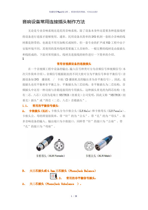
1常用音视频设备的连接插头在一个音视频工程中设备的输出、输入信号种类可分为音频信号和视频信号(本次只作简单介绍);音频信号根据阻抗的不同大致可分为平衡信号和非平衡信号(音源设备如DVD 播放机/ 卡座/ CD播放机及的输出多为非平衡信号)。
因此,连接插头也有平衡和非平衡之分,平衡插头为三芯结构,非平衡插头为二芯结构。
音频插头中还有一种功放与音箱连接用的专用插头,这种插头常见的为四芯结构(也有二芯、八芯)又因为是瑞士NEUTRIK(纽垂克)公司发明,因此又称“NEUTRIK(纽垂克)插头”或“四芯(二芯、八芯)音箱插头”。
1.1、常用的平衡信号插头:A、卡侬插头(XLR):卡侬头分为卡侬公头(XLR Male)和卡侬母头(XLR Female)。
卡侬头公、母的辨别很简单,带“针”的为“公头”,带“孔”的为“母头”。
很多音响设备的输入、输出端口为卡侬接口,同样带“针”的接口为“公座”,带“孔”的接口为“母座”。
B、大三芯插头或6.3mm三芯插头(PhoneJack Balance)1.2、常用的非平衡信号插头:A、大二芯插头(PhoneJack Unbalance )。
B、莲花插头(RCA)C、小三芯插头或3.5mm三芯插头小三芯插头外观与大三芯插头类似只是体积要比大三芯小。
小三芯插头为三芯,前面说过三芯为平衡信号插头,但在通常的音响工程中小三芯插头多用于电脑及便携式音源(便携CD / MP3等)的音频信号输出用,因此将小三芯插头归入非平衡信号插头之列。
光纤快速连接器的制作流程
光纤快速连接器的制作流程光纤快速连接器,这小玩意儿可有点技术含量,但别怕,咱一步步来捣鼓它。
做光纤快速连接器,材料得先备齐。
就像做饭得有食材一样,光纤、插芯、尾套这些是必不可少的。
光纤那可是关键,就像血管一样,传输着重要的信息呢。
插芯就像是一个小房子,要给光纤安个家。
尾套呢,就像是给这个小家围个小院子,起到保护的作用。
先来说光纤的处理。
光纤很脆弱的,就像小姑娘的发丝一样,得小心翼翼。
要把光纤的外皮剥掉,这可不能心急,一急就容易把光纤弄断。
剥的时候,用专门的剥纤工具,就像给光纤脱衣服,一点点地把那层保护外皮去掉,露出里面光溜溜的光纤芯。
这时候的光纤芯,亮晶晶的,感觉像是藏着神秘力量的小魔杖。
接下来就是把光纤插到插芯里。
插芯那个小洞口,就像个小嘴巴,等着光纤这个小食物塞进去呢。
不过塞的时候得注意,要让光纤笔直地进去,不能歪了。
要是歪了呀,就像人走路走歪了一样,会出问题的。
把光纤慢慢推进插芯,推到合适的位置,这个合适的位置就像是给光纤找到了它最舒服的小床。
然后就是固定光纤了。
这就好比给光纤系上安全带,让它在插芯里稳稳当当的。
有的是用胶水固定,胶水就像个小黏人精,紧紧地抱住光纤,不让它乱动。
不过涂胶水的时候也要小心,不能涂太多,不然就像吃面条放太多酱,会糊成一团的。
再把尾套套上去。
尾套套上的那一刻,就像给这个小家庭关上了大门,起到最后的保护作用。
尾套要套得严严实实的,就像给插芯和光纤穿上了一件厚厚的铠甲,防止外界的伤害。
做完这些基本的步骤后,还得测试一下。
测试就像是给光纤快速连接器做个体检。
看看它能不能正常地传输信号。
要是测试不通过,那就得像医生看病一样,重新检查各个步骤,看看是哪里出了问题。
也许是光纤没插好,也许是胶水涂多了影响了信号传输,反正就得像侦探一样,把问题找出来解决掉。
在整个制作光纤快速连接器的过程中,心态很重要。
不能毛躁,要像绣花一样细致。
有时候可能做了一次不成功,别灰心,就像小孩学走路,摔了一跤再爬起来接着走就好。
光纤接头的制作和连接
光纤头的制作和连接
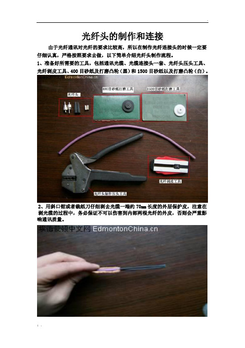
由于光纤通讯对光纤的要求比较高,所以在制作光纤连接头的时候一定要仔细认真,严格按照要求去做,以下简单介绍光纤头制作流程。
1、准备好所需要的工具,包括通讯光缆、光缆连接头一套、光纤头压头工具、光纤剥皮工具、400目砂纸及打磨凸轮(黑)和1500目砂纸以及打磨凸轮(白)。
2、用斜口钳或者裁纸刀仔细剥去光缆一端约70mm长度的外层保护皮,注意在剥光缆的过程中,务必保证不可以伤害到内部两根光纤的外皮,否则会严重影响通讯质量。
3、使用光纤剥皮工具将两根光纤头部剥去1mm左右长度的外皮,将光纤插入工具前端的小孔内,调整中间活动挡板到合适的距离,然后按紧两侧压扭让刀片卡进光纤皮,然后向外拉出光纤将光纤外皮剥除。
4、然后分别将光纤头组件套入到光纤上。
5、使用光纤头压头工具进行光纤头压制工作,将光纤伸入到光纤头内,要伸入到光纤头档口,然后把金属套筒套入光纤头的光纤入口处,要完全套入底部,把套好的光纤头放置于压头工具3.25口处进行压制。
用3.25的孔!
进行压制和压制成型。
6、将长出光纤头的光纤用斜口钳进行剪除,保留有3-5mm左右长度。
来个特写。
7、剪切好后开始用400目的砂纸以及黑色的凸轮进行打磨,打磨的时候要按照8子型线路滑动打磨,保证打磨面全面光滑。
8.用400目砂纸将两个光纤头打磨完毕后,同样的方法使用1500目砂纸和白色凸轮继续进行打磨。
9、随后将已经打磨好的光纤头安装进要连接的OLM(光电转换器)
最后一句话..........没了。
最后两句话.......还是没了。
有钱的给个前场,没钱的给个人场!。
FTTH三种快速连接方式介绍-27页精品文档

22
非预埋快速连接器工装夹具
21.09.2019
苏州新海宜通信科技股份有限公司
23
非预埋快速连接器安装概要
说明:以下步骤中,必须保证产品及光纤的清洁
1、穿尾套、连接管
2、按刻度剥光缆
3、靠齐剥光纤
4、光纤切割
5、穿光纤
6、夹光纤
21.09.2019
苏州新海宜通信科技股份有限公司
24
非预埋快速连接器安装概要
5
21.09.2019
快速热熔接技术
热剥器-能以高达3.5kgf的 拉力进行热剥
热剥无裂痕 带电机,可进行100万次以上的热剥操作 热剥时间-1.5秒
清洗
由于采用的是V形槽熔接法,V形槽的清洗尤其重要
切割
一次切割 油阻尼器系统设备 内置光纤碎屑收集器
加热缩套管
说明:以下步骤中,必须保证产品及光纤的清洁
7、安装定位卡片
8、压光缆
9、安装外壳
10、成品
21.09.2019
苏州新海宜通信科技股份有限公司
25
谢谢!
21.09.2019
苏州新海宜通信科技股份有限公司
26
250um和900um任意组合
简单操作即可完成接续,无需接
续保护托盘
护套夹有助于释放900um紧护套的
应力
VHB高强度背胶,可根据应用场合
灵活放置
苏州新海宜通信科技股份有限公司
14
现场组装型光纤连接器系列1
产品描述:
适用于皮线入户单模光纤 现场快速端接及互联 具备与标准SC连接器同等的接续能力 兼容标准SC连接器 光缆无多余的余长,方便管理 所需工具系列1通用,操作简单,无需电源,大幅降低工
- 1、下载文档前请自行甄别文档内容的完整性,平台不提供额外的编辑、内容补充、找答案等附加服务。
- 2、"仅部分预览"的文档,不可在线预览部分如存在完整性等问题,可反馈申请退款(可完整预览的文档不适用该条件!)。
- 3、如文档侵犯您的权益,请联系客服反馈,我们会尽快为您处理(人工客服工作时间:9:00-18:30)。
光纤快速接器的特点
光纤快速接器的特点 不需要对光纤进行特殊的抛光处理 安装时不需要复杂的工具(只需要剥线器和切割
刀) 制作简单快捷 可重复使用
驻马店分公司
快速连接器的类型
◆根据快速连接器的构造可分为: 预埋型:
–生产过程中,在陶瓷芯前段预埋裸纤,且端面 经过精密的研磨处理和检验。
驻马店分公司
快速连接插头的制作
将 入户皮线光缆放置于切割适配器内。外护套 剥离处与适配器内底部的标线对齐。 将切割适配器放置于切割刀适配器槽内,进行 光纤切割。 当入户皮线光缆的外皮到达光缆限位处时,停 止插入光纤。涂覆层可以明显观察到弯曲。
驻马店分公司
快速连接插头的制作
确认光纤的弯曲,并保持弯曲,向下按压主 体上白色的压接盖到底,并均匀用力压 3 次。 释放光纤的弯曲,使其平直。(可以用手把 两夹片往外掰,让皮线缆自然平直)
光纤冷接续技术
—— 光纤机械接续取代熔接机
光纤/光缆现场端接光纤插头、插座
—— 取代工厂制作的定长尾纤/跳线
光纤插座/插头端接概念
—— 无论光纤停在何处,都要在插座/插头 内端接保护
入户皮线光缆
—— 高性能入户光缆取代传统的尾纤
• 通过简化光纤/缆处理和降低接续操作成本 • 使光缆的施工接续和铜缆施工一样容易!!
驻马店分公司
快速连接插头的制作
1
2
3
4
快速连接插头 5 制作工具
6
7
8
9
编号 1 2 3 4 5
名称 酒精瓶 无纺布 切割刀 剥线钳 记号笔
编号 6 7 8 9
名称 剪刀 适配器 重复开启工具 连接插头及 包装袋
驻马店分公司
快速连接插头的制作
打开包装袋,连接器共有 3 个部件:
1.主体 2.外壳 3.尾帽。
驻马店分公司
快速连接插头的制作
在蝶形引入光缆两端制作光纤机械接续连接插 头时,必须对光缆进行基本处理,其内容包括: 蝶形引入光缆的开剥与护套的去除、剥离光纤的 涂覆层、裸纤的清洁及其端面的切割等。这些基 本处理在使用不同厂商的光纤机械接续连接插头 中是相同的,也是非常重要的步骤。基本处理的 恰当与否,会直接影响光纤机械接续连接插头制 作的质量,所以细心的同时还必须要有熟练的技 术。
驻马店电信公司 FTTH 入户光缆快速连接器制作
培训课件
中国电信驻马店分公司 朱旭峰 2012年3月
驻马店分公司
提纲
第一部分 光纤快速连接器概念及应用 第二部分 光纤快速链接器的制作 第三部分 光纤快速链接器的测试 第四部分 总结
驻马店分公司
第一部分
FTTH光纤快速连接器概念及应用
驻马店分公司
概念及应用
注意:保留包装袋。
用斜口钳把皮线缆前端 10cm 剪掉,因为皮线布 放施工时前端有可能因受 力而折断
驻马店分公司
快速连接插头的制作
根据包装袋上的图示,用记号笔在离外护套剥离 处 24mm 的位置做标记,标记在 涂覆层上。(涂覆层 可能是白色或者蓝色) 从 24mm 标记处剥除涂覆层,用开剥刀 45 度角 向外把涂覆层剥掉,并用蘸有无水酒精的无纺布清洁 光纤 2 次。
驻马店分公司
快速连接插头的制作
• 制作光纤机械接续连接插头是FTTH入户光缆施工 中最基本的一项技术,也是一门不可缺少的基本 功。光纤机械接续连接插头制作质量的优劣不仅 直接影响光纤传输损耗的容限,影响传输距离的 长度,而且会影响系统使用的稳定性、可靠性。 一般SC型单芯光纤机械接续连接插头和连接插座 (适配器)组成的插拔式机械接续连接器的连接 损耗应控制在0.5dB以下(最好在0.3 dB以下)。
–现场对用户光缆的光纤端面进行切割,并通过 内置对准机构和预埋裸纤机械连接。 直插型:
–生产过程中,陶瓷芯完全贯通。 –现场对用户光缆的光纤端面进行切割, 直接
插入陶瓷芯,端面在现场不再经过研磨和检验 。
驻马店分公司
快速连接器的类型
预埋光纤型接头内,预埋光纤和现场光纤在V槽等装 置内被固定,接头内部有预留空间,可以使光纤预先 设置一定的余长,即使尾端固定时产生位移,也可在 此处进行位移补偿和应力释放。 内部光纤对接使用了匹配液消除光的反射,并减小连 接损耗
驻马店分公司
快速连接插头的制作
将尾帽套上连接器主体,并旋紧。 套上外壳,外壳上的空槽和主体上白色 压接盖的方向应一致,制作完成。
驻马店分公司
快速连接插头的开启
将防尘帽套在陶瓷芯上,然后用手指捏 紧连接器外壳,向下顶压,取出外壳。 将尾帽旋松并后退脱离连接器本体。
驻马店分公司
快速连接插头的开启
取下主体上的防尘帽后,对应3 个缝隙位置,将 连接器放置在重复开启工具上。用力将主体向重复开 启工具按压,将主体上的压接盖顶起。 将光纤从连接器主体内小心轴向抽出,注意取出 的过程尽量不要晃动光纤和主体,避免裸纤意外断裂 在连接器内导致无法重复使用,开启完毕。
驻马店分公司
快速连接插头制作注意事项
在 在连接器整个安装过程中,各个环节要保障清洁
安装时,才将单个连接器从防尘包装中取出; 确认切割刀干净,同时在切割的时候没有灰尘
和污垢; 在切割前用无尘纸蘸酒精擦拭现场光纤; 一旦现场光纤切割好,将其立即放入连接器
并进行端接处理,避免切割以后光纤被污损。
驻马店分公司
快速连接插头制作注意事项
驻马店分公司
快速连接器的类型
直插光纤型接头内,现场光纤在陶瓷插芯内 是松动的,在固定尾端光缆时,会影响光纤 的纵向位移,在插拔过程中,会出现耦合光 功率不稳定等现象
驻马店分公司
• 光纤插头端的应用
快速连接器的应用
光缆接头盒 住宅ONU 光分配盒 光分配箱
驻马店分公司Βιβλιοθήκη 第二部分 快速连接插头的制作
确保现场光纤切割端面质量 选用合适的现场光纤切割刀; 严格按照切割刀操作规范作业; 光纤放在下压纤垫上要平直,才能获得好的切割
端面角度。
驻马店分公司
快速连接插头制作注意事项
现场光纤与预埋光纤两端面的紧密贴合是成功 端接的关键 现场切割的光纤长度要精准,现场光纤长度
不够,没有和工厂预磨的短光纤接触上,将导 致端面之间存在一个间隙,增加端接损耗。 现场切割的光纤长度要精准,穿纤到位,光 纤合理弯曲,提供两端面贴紧力,确保端面接 触,同时避免光纤过长,造成端面压力过大, 引起光纤端面损坏。
