CID 2011756_638156-11-3_DataSheet_MedChemExpress
63811-5200中文资料
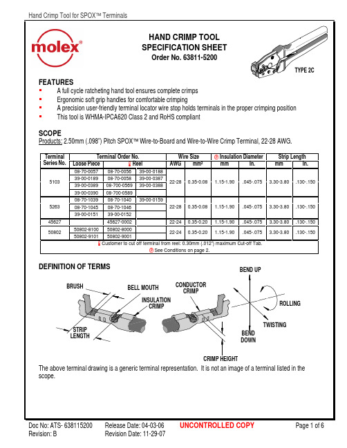
FEATURESA full cycle ratcheting hand tool ensures complete crimpsWarrantyThis tool is for electrical terminal crimping purposes only. This tool is made of the best quality materials. All vital components are long life tested. All tools are warranted to be free of manufacturing defects for a period of 30 days. Should such a defect occur, we will repair or exchange the tool free of charge. This repair or exchange will not be applicable to altered, misused, or damaged tools. This tool is designed for hand use only. Any clamping, fixturing, or use of handle extensions voids this warranty.CAUTION: Molex crimp specifications are valid only when used with Molex terminals and tooling. CAUTIONS1. Manually powered hand tools are intended for low volume or field repair. This tool is NOT intended forproduction use. Repetitive use of this tool should be avoided.2. Insulated rubber handles are not protection against electrical shock.3. Wear eye protection at all times.4. Use only the Molex terminals specified for crimping with this tool.CertificationMolex does not certify or re-certify commercial grade hand tools but rather supplies the following guidelines for customers to re-certify hand tools.% This tool is qualified to pull force only. To re-certify, crimp a terminal to a wire, which has been stripped12.7mm (1/2”) long, so there is no crimping of the insulation. Pull the terminal and wire at a rate no faster than25mm (1.00”) per minute. See the Molex web site for the Quality Crimp Handbook for more information on pull testing.% If the tool does not meet minimum pull force values, handle preload should be increased and the pull test rerun, (See How To Adjust Preload).% When the hand tool is no longer capable of achieving minimum pull force, it should be taken out of service and replaced.。
超米特电子有限公司产品说明书

1US Headquarters TEL +(1) 781-935-4850FAX +(1) 781-933-4318 • Europe TEL +(44) 1628 404000FAX +(44) 1628 404090Asia Pacific TEL +(852) 2 428 8008FAX +(852) 2 423 8253South America TEL +(55) 11 3917 1099FAX +(55) 11 3917 0817Superior elongation and tensilestrength help to prevent tearing in use due to mishandling. Typical properties for CHO-SEAL 1310 and 1273 materi-al are shown on pages 33 and 32respectively.High Shielding PerformanceCHO-SEAL 1310 material provides more than 80 dB of shielding effectiv-ness from 100 MHz to 10 GHz, while CHO-SEAL 1273 material provides more than 100 dB.Low Volume ResistivityBoth materials have exceptionally low volume resistivity, which makes them well suited for grounding appli-cations in which a flexible electrical contact is needed.Low Compression GasketSpacer gaskets are typicallydesigned to function under low deflec-tion forces. Chomerics uses design tools such as Finite Element Analysis (FEA) to accurately predict compres-sion-deflection behavior of various cross section options. Refer to page16.LCP Plastic SpacerLiquid crystal polymer (LCP)spacers, including those made with Vectra A130 material, provide aCHO-SEAL ®1310 or 1273Conductive ElastomersWith EMI spacer gaskets, shielding and grounding are provided by Chomerics’CHO-SEAL 1310 and 1273 conductive elastomers, specifi-cally formulated for custom shape molded parts. They provide excellent shielding and isolation against electro-magnetic interference (EMI), or act as a low impedance ground path between PCB traces and shielding media. Physically tough, these elas-tomers minimize the risk of gasket damage, in contrast to thin-walled extrusions or unsupported molded gaskets.Silicone-based CHO-SEAL 1310and 1273 materials offer excellent resistance to compression set over a wide temperature range, resulting in years of continuous service. CHO-SEAL 1310 material is filled with silver-plated-glass particles, while 1273 utilizes silver-plated-copper filler to provide higher levels of EMI shielding effectiveness.EMI Spacer GasketsThe unique design of Chomerics’EMI spacer gaskets features a thin plastic retainer frame onto which a conductive elastomer is molded. The elastomer can be located inside or outside the retainer frame, as well as on its top and bottom surface. EMI spacer gaskets provide a newapproach to designing EMI gaskets into handheld electronics such as dig-ital cellular phones. Board-to-board spacing is custom designed to fit broad application needs. Customized cross sections and spacer shapes allow for very low closure forcerequirements and a perfect fit in any design or device.Robotic InstallationSpacer gaskets can be installed quickly by robotic application. Integral locater pins in the plastic spacer help ensure accuratepositioning in both manual and pick-and-place assembly. Benefits include faster assembly and lower labor costs.The integrated conductive elastomer/plastic spacer gasket is a low cost,easily installed system for providing EMI shielding and grounding in small electronic enclosures.Figure 1Single Piece EMI Gasket/Locator PinsCHO-SEAL 1310 or 1273 Conductive Elastomer (Inside)Plastic Spacer Around Outsideor InsideApplications for EMI Spacer GasketsThe spacer gasket concept is especially suited to digital and dual board telephone handsets or other handheld electronic devices. It provides a low impedance path between peripheral ground traces on printed circuit boards and components such as:•the conductive coating on a plastic housing•another printed circuit board •the keypad assemblyTypical applications for EMI spacer gaskets include:•Digital cellular, handyphone and personal communications services (PCS) handsets •PCMCIA cards•Global Positioning Systems (GPS)•Radio receivers•Other handheld electronics, e.g.,personal digital assistants (PDAs)•Replacements for metal EMI shield-ing “fences” on printedcircuit boards in wireless tele-communications devicesstable platform for direct, highprecision molding of conductive elas-tomers. The Vectra A130 material described in Table 1 has excellent heat deflection temperature character-istics (489°F, 254°C). For weight con-siderations, the LCP has aspecific gravity of only 1.61. This plas-tic is also 100% recyclable.Typical EMI Spacer Gasket Design ParametersThe EMI spacer gasket concept can be considered using the design parameters shown in Table 2. Some typical spacer gasket profiles are shown below.Figure 2Typical Spacer Gasket Profiles3US Headquarters TEL +(1) 781-935-4850FAX +(1) 781-933-4318 • Europe TEL +(44) 1628 404000FAX +(44) 1628 404090Asia Pacific TEL +(852) 2 428 8008FAX +(852) 2 423 8253South America TEL +(55) 11 3917 1099FAX +(55) 11 3917 0817Finite Element AnalysisChomerics, a division of the Parker Hannifin Corporation’s Seal Group, is the headquarters of Parker Seal’s Elastomer Simulation Group. This unit specializes in elastomer finite element analysis (FEA) using MARC K6 series software as a foundation for FEA capability.Benefits of FEA include:•Quickly optimizing elastomer gasket designs•Allowing accurate predictions of alternate elastomer design concepts •Eliminating extensive trial and error prototype evaluationTypical use of FEA in EMI spacer gasket designs is to evaluate the force vs. deflection requirements of alternate designs.For example, onespacer design features a continuous bead of con-ductive elastomer molded onto a plastic spacer. An alternative designemploys an “interrupted bead,” where the interrup-tions (gaps left on the plastic frame) are sized to maintain the requiredlevel of EMI shielding. Figure 4illustrates these alternative designs.Gasket DeflectionFigure 5 compares the effect of continuous and interrupted elastomer gasket designs in terms of the force required to deflect the conductive elastomer. This actual cellular handset application required a spacer gasket with interrupted bead to meet desired deflection forces.Chomerics Designand Application ServicesChomerics will custom design a spacer for your application. Advice,analysis and design assistance will be provided by Chomerics Applications and Design engineers at no additional fee. Contact Chomerics directlyat the locations listed at the bottom of the page.Figure 3FEA Example of an EMISpacer Gasket Cross SectionFigure 4Continuous (top) and InterruptedElastomer GasketsFigure 5Typical Spacer Gasket Deflection。
GigaSPEED XL 3071E-B ETL Verified Category 6 U UTP
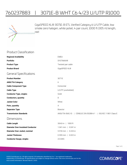
GigaSPEED XL® 3071E-B ETL Verified Category 6 U/UTP Cable, lowsmoke zero halogen, white jacket, 4 pair count, 1000 ft (305 m) length,reelProduct ClassificationRegional Availability EMEAPortfolio SYSTIMAX®Product Type Twisted pair cableProduct Brand GigaSPEED XL®General SpecificationsProduct Number3071EANSI/TIA Category6Cable Component Type HorizontalCable Type U/UTP (unshielded)Conductor Type, singles SolidConductors, quantity8Jacket Color WhitePairs, quantity4Separator Type BisectorTransmission Standards ANSI/TIA-568.2-D | CENELEC EN 50288-6-1 | ISO/IEC 11801 Class E DimensionsCable Length304.8 m | 1000 ftDiameter Over Insulated Conductor 1.041 mm | 0.041 inDiameter Over Jacket, nominal 5.918 mm | 0.233 inJacket Thickness0.559 mm | 0.022 inConductor Gauge, singles23 AWG13Page ofCross Section DrawingElectrical Specificationsdc Resistance Unbalance, maximum 5 %dc Resistance, maximum7.61 ohms/100 m | 2.32 ohms/100 ftDielectric Strength, minimum2500 VdcMutual Capacitance at Frequency 5.6 nF/100 m @ 1 kHzNominal Velocity of Propagation (NVP)70 %Operating Frequency, maximum300 MHzOperating Voltage, maximum80 VRemote Powering Fully complies with the recommendations set forth by IEEE 802.3bt (Type4) for the safe delivery of power over LAN cable when installed accordingto ISO/IEC 14763-2, CENELEC EN 50174-1, CENELEC EN 50174-2 or TIATSB-184-ASegregation Class cMaterial SpecificationsConductor Material Bare copperInsulation Material PolyolefinJacket Material Low Smoke Zero Halogen (LSZH)Separator Material PolyolefinPage of23Mechanical SpecificationsPulling Tension, maximum11.34 kg | 25 lbEnvironmental SpecificationsInstallation temperature0 °C to +60 °C (+32 °F to +140 °F)Operating Temperature-20 °C to +60 °C (-4 °F to +140 °F)Acid Gas Test Method EN 50267-2-3EN50575 CPR Cable EuroClass Fire Performance B2caEN50575 CPR Cable EuroClass Smoke Rating s1aEN50575 CPR Cable EuroClass Droplets Rating d0EN50575 CPR Cable EuroClass Acidity Rating a1Environmental Space Low Smoke Zero Halogen (LSZH)Smoke Test Method IEC 61034-2Packaging and WeightsCable weight38.097 kg/km | 25.6 lb/kftPackaging Type ReelRegulatory Compliance/CertificationsAgency ClassificationCENELEC EN 50575 compliant, Declaration of Performance (DoP) availableCHINA-ROHS Below maximum concentration valueISO 9001:2015Designed, manufactured and/or distributed under this quality management system REACH-SVHC Compliant as per SVHC revision on /ProductCompliance ROHSCompliantPage of33。
5-1181-12S;5-1181-12;5-1181-34S;5-1181-34;5-1181-1S;中文规格书,Datasheet资料

1181 TapeCopper Foil with Conductive AdhesiveData SheetProduct Description3M ™ 1181 Tape consists of a 1-ounce deadsoft copper foil backing and a unique electrically conductive pressure-sensitive acrylic adhesive.• Deadsoft 1-ounce copper foil backing • Conductive acrylic adhesive• Supplied on a removable liner for easy handling and diecuttingLike all 3M shielding tapes, 3M 1181 isavailable in standard and custom widths and lengths. Standard length is 18 yards.• Widths from 1/4” to 23”• Longer lengths up to several times normal length, dependent upon width. Check with Customer Service.Applications3M 1181Tape is typically used forapplications requiring excellent electrical conductivity from the application substrate through the adhesive to the foil mon uses include grounding and EMI shielding in equipment, components, shielded rooms, etc. The copper foil backing is solderable and resists oxidation and discoloration.Shielding EffectivenessMany factors determine the true shielding effectiveness of a shielding tape, including type and thickness of foil, adhesive type,intimacy of contact, smoothness ofapplication surface, strength and frequency of the EMI signal, etc. However, using standard tests and fixtures, it is possible to determine a value for the attenuation.For 3M 1181 Tape, typical shieldingeffectiveness (far field) is in the range of 60dB to 80dB (30 MHz to 1 GHz).Properties Typical ValuesBacking thickness 11.4 mil (0,04mm)Total thickness (backing plus adhesive) 22.6 mil (.066mm)Breaking strength 1 25 lb./in (44 N/10mm)Adhesion to steel 135 oz/in (3,8 N/10mm)Electrical resistance through adhesive 20.005 ohmFlame retardancy 3 Pass* Footnote: 1. Test method ASTM D 10002. MIL-STD-202 Method 3 07 maintained at 5 psi (3,4 N/cm 2) measured over 1 in 2 surface area. Conductive particles in the adhesiveprovide the electrical path between the application substrate and the foil backing.3. UL-recognized for flame retardancy per UL 510, Product Category 0ANZ2, File E17385./3M is a trademark of 3M. Important NoticeAll statements, technical information and recommendations related to the Seller’s products are based on information believed to be reliable, but the accuracy or completeness thereof is not guaranteed. Before utilizing the product, the user should determine the suitability of the product for its intended use. The user assumes all risks and liability whatsoever in connection with such use.Any statements or recommendations of the Seller which are not contained in the Seller’s current publications shall have no force or effect unless contained in an agreement signed by an authorized officer of the Seller. The statements contained herein are made in lieu of all warranties,expressed or implied, including but not limited to the implied warranties of merchantability and fitness for a particular purpose which warranties are hereby expressly disclaimed. SELLER SHALL NOT BE LIABLE TO THE USER OR ANY OTHER PERSON UNDER ANY LEGAL THEORY, INCLUDING BUT NOT LIMITED TO NEGLIGENCE OR STRICT LIABILITY, FOR ANY INJURY OR FOR ANY DIRECT, INDIRECT, SPECIAL, INCIDENTAL OR CONSEQUENTIAL DAMAGES SUSTAINED OR INCURRED BY REASON OF THE USE OF ANY OF THESELLER’S PRODUCTS THAT WERE DEFECTIVE.Electrical Products Division6801 River Place Blvd.Austin, TX 78726-9000800 676 8381/elpd© 3M 199878-8124-4702-3 /分销商库存信息:3M5-1181-1/2S5-1181-1/25-1181-3/4S5-1181-3/45-1181-1S5-1181-1/2-2R5-1181-15-1181-3/4-2R5-1181-1/2-3R5-1181-1-2R5-1181-1/2-4R5-1181-1.5S5-1181-3/4-3R5-1181-2S5-1181-1-4R5-1181-1.55-1181-1-3R5-1181-3/4-4R5-1181-23M 1181 0.5"SQ-2503M 1181 1/2" X 2"-100 3M 1181 CIRCLE-0.5"-2503M 1181 0.75"SQ-2503M 1181 3/4" X 2"-100 3M 1181 1/2" X 3"-1003M 1181 1" X 2"-1003M 1181 1/2" X 4"-100 3M 1181 1.5"SQ-1003M 1181 3/4" X 3"-1003M 1181 CIRCLE-0.75"-2503M 1181 1"SQ-2503M 1181 CIRCLE-1.5"-1003M 1181 1" X 3"-1003M 1181 3/4" X 4"-1003M 1181 CIRCLE-1"-2503M 1181 2"SQ-1003M 1181 1" X 4"-1003M 1181 CIRCLE-2"-1001181 X 1/4"1181 X 1/2"1181 X 1"1181 X 6"1/2-6-11813-6-118123X36-1-118111.5-6-11811181 TAPE (1/8)1181 1/8 X 18 YDS 11.5X12-6-11813/4-6-11811-6-11812-6-11814-6-11816-6-1181。
6381-35 LIQUID FLUX 产品说明书

6381-35 5LFicha de Datos de Seguridad según la Directiva (CE) nº 1907/2006 - ISO 11014-1página 1 de 7Nº SDB : 182779V002.1Revisión: 30.03.2010Fecha de impresión: 16.08.2011 6381-35 LIQUID FLUX1. Identificación de la sustancia o preparado y de la sociedad o empresaNombre comercial:6381-35 LIQUID FLUXUso previsto:Flux líquidoDenominación de la empresa:Henkel Ibérica S.A.C/. Córcega; 480-49208025 BARCELONAEspañaTeléfono: +34 (932904647)Fax: +34 (932904700)Responsable de la ficha de datos de seguridad:*****************************.comInformación de emergencia:Henkel Ibérica S.A. 93 290 41 00 (24 h)2. Posibles peligros del productoR11 Fácilmente inflamable.R36 Irrita los ojos.R43 Posibilidad de sensibilización en contacto con la piel.R67 La inhalación de vapores puede provocar somnolencia y vértigo.Los humos emitidos a temperatura de soldadura causarán irritación de lasmembranas mucosas, la garganta y los pulmones.La exposición prolongadao repetida a humos de fundente de producirá irritaciones entrabajodores sensibles.3. Composición / datos sobre los componentesDeclaración de componentes según la Regulación (CE) n o 1907/2006:Ingredientes peligrososN° CAS EINECSELINCScontenido ClasificaciónPropan-2-ol 67-63-0 200-661-7 40 - 50 % F - Fácilmente inflamable; R11Xi - Irritante; R36R67Colofonia 8050-09-7 232-475-7 30 - 40 %R432-(2-Butoxietoxi)etanol112-34-5203-961-6 10 - 20 % Xi - Irritante; R36Destilados (petróleo), fracción ligeratratada con hidrógeno64742-47-8265-149-8 1 - 5 % Xn - Nocivo; R65 El texto completo de las frases R aquí indicadas puede verse en el punto 16 "Otras informaciones".Nº SDB: 182779 V002.16381-35 LIQUID FLUX página 2 de 7 Para sustancias sin clasificación pueden existir límites de exposición en los lugares de trabajo.4. Medidas de primeros auxiliosInhalación:Sacar al aire libre. Si persisten los síntomas buscar asistencia médica.Contacto de la piel:Lavar con agua corriente y jabon.Si la irritación persiste consultar a un médico.Contacto con los ojos:Lavar bajo agua corriente (durante 10 min.), acudir al médico.Ingestión:No provocar vómitos.Consultar con un médico.5. Medidas para la lucha contra incendiosExtintor apropiado:Espuma resistente al alcohol.Dióxido de carbono.Polvo seco.Equipo de protección especial para el personal de lucha contra incendios:Llevar puesta protección respiratoria independiente del aire ambiente.Peligros especiales debidos al producto mismo:Puede formarse una mezcla explosiva de gas y aire.Formación de productos de combustión o gases:Óxidos de carbono.La descomposición térmica puede llegar a desprender gases y vapores irritativos.6. Medidas en caso de liberación imprevistaMedidas de precaución personales:Evitar el contacto con los ojos y la piel.Utilicese indumentaria de protección personal.Medidas medio ambientales:No dejar que el producto entre en el sistema de alcantarillado.Impedir nuevos escapes o derrames de forma segura.Proceso para la limpieza y la recogida:Retirar todas las fuentes de ignición.En caso de pequeños derrames, enjuagar con toalla de papel y desecharla en recipiente adecuado.En caso de grandes derrames, absorber en material absorbente e inerte y desecharlo en recipiente hermético.7. Manejo y almacenamientoManejo:Utilícese solo en zonas bien ventiladas.Conservar alejado de fuentes de ignición. - No fumar.Usar protección de los ojos, ponerse guantes y ropa protectora.Lávense las manos antes de los descansos e inmediatamente después de manipular la sustancia.Tomar medidas contra cargas electroestáticas.Nº SDB: 182779 V002.16381-35 LIQUID FLUX página 3 de 7 Almacenamiento:Guardar el recipiente en un lugar fresco, bien ventilado.Conservar alejado de las fuentes de ignición.8. Limitación de exposición y equipo de protección personalComponentes con valores límite referidos al puesto de trabajo que tienen que supervisarse:Válido paraEspañaFundamentoLímites de Exposición Profesional para Agentes Químicos en EspañaComponente ppm mg/m3 Tipo Categoría Observación ALCOHOL ISOPROPÍLICO67-63-0500 1.250 Límites a corto plazo. VLAALCOHOL ISOPROPÍLICO 67-63-0 400 998 Media ponderada en eltiempo.VLARESINA NÚCLEO DE SOLDADURA (COLOFONIA)8050-09-7 La sustancia se indica nominalmente en la listaoficial, pero sin asignación de valores. Debe tener en cuentael texto original de laregulación.VLA2-(2-BUTOXIETOXI) ETANOL 112-34-5 10 67,5 Media ponderada en eltiempo.VLA2-(2-BUTOXIETOXI) ETANOL112-34-515 101,2 Límites a corto plazo. VLA2-(2-BUTOXIETOXI)ETANOL 112-34-5 10 67,5 Media ponderada en eltiempo.EU-2000/39/EC2-(2-BUTOXIETOXI)ETANOL112-34-515 101,2 Límites a corto plazo. EU-2000/39/ECIndicaciones acerca la estructuración instalaciones técnicas:Asegurarse de una ventilación adecuada, especialmente en locales cerrados.Donde sea razonablemente practicable, esto deberá ser realizado usando ventilación local y una buena extracción general.Deben extraerse los humos emitidos durante la soldadura.Protección respiratoria:En caso de insuficiente ventilación, utilizar equipo respiratorio adecuado.Protección manual:Guantes protectores resistentes a productos químicos (EN 374). Materiales apropiados en caso de contacto breve osalpicaduras (recomendado: Mínimo índice de protección 2, correspondiente >30 minutos tiempo de permeación según EN374 Caucho nitrilo (IIR; >= 0,4 mm espesor de capa) Materiales apropiados también en caso de contacto directo yprolongado (recomendado: índice de protección 6, corresponde >480 minutos tiempo de permeación según EN 374 Cauchonitrilo (IIR; >= 0,4 mm espesor de capa) Los datos se han extraído de la bibliografía y la información de los fabricantes deguantes o bien se han deducido por analogía de materiales similares. Debe tenerse en cuenta que la duración de uso de unguante de protección química puede ser mucho más corta en la práctica debido a los múltiples factores de influencia (p. ej.temperatura) que el tiempo de permeación calculado según EN 374. Si aparecen síntomas de desgaste, deben cambiarse losguantes.Protección ocular:Si existe riesgo de salpicaduras, utilizar gafas de seguridad con protectores laterales o para uso con productos químicos.9. Propiedades físicas y químicasPropiedades generales:Aspecto LíquidoamarilloOlor: TipoAlcoholPropiedades físico químicas:ValorpH noaplicableNº SDB: 182779 V002.1 6381-35 LIQUID FLUXpágina 4 de 7Punto de ebullición 82,0 °C (179.6 °F) Punto de inflamación 12,0 °C (53.6 °F) Presión de vapor(25,0 °C (77 °F))6,6 kPa Densidad(25 °C (77 °F))0,897 g/cm3Solubilidad cualitativa(Disolvente: Agua)Parcialmente miscible Limietación de explosióninferior [vol%] superior [vol%]2,00 %(V) 12,00 %(V) Coeficiente de distribución octanol/agua Indeterminado Tenor VOC(1999/13/EC) 60 - 70 %10. Estabilidad y reactividadCondiciones a evitar: EstableMateriales a evitar:Reacción con oxidantes fuertes.Disuelve el aluminio y el cinc lentamente con formación de hidrógeno.Productos de descomposición peligrosos:La descomposición térmica puede llegar a desprender gases y vapores irritativos.11. Información toxicológicaToxicidad oral aguda:Puede ocasionar irritación en el aparato digestivo.La ingestión de grandes cantidades puede causar lesiones en el hígado o los riñones.Toxicidad inhalativa aguda:La inhalación de concentraciones altas de vapor pueden originar síntomascomo dolor de cabeza, vértigo o desvanecimiento, cansancio, náuseas yvómitos.Los humos emitidos a temperatura de soldadura causarán irritación de lasmembranas mucosas, la garganta y los pulmones. La exposición prolongadao repetida a humos de fundente de producirá irritaciones entrabajodores sensibles.Irritación de la piel:El contacto prologado o repetido puede causar irritación en la piel.Irritación de los ojos:Irritante para los ojos.El líquido podría producir irritación conjuntival.Sensibilización:Posible sensibilización por contacto con la piel.12. Información ecológicaEfectos ecotoxicológicos::No verter en el desagüe/ aguas de superficie /aguas subterráneas.Movilidad:No hay datos.Potencial de bioacumulación:Coeficiente de distribución octanol/agua: IndeterminadoNº SDB: 182779 V002.16381-35 LIQUID FLUX página 5 de 7 Efectos ecotoxicológicos::Ingredientes peligrososN° CAS Especies TiempodeexposiciónTipodevalorValorColofonia8050-09-7Fathead minnow (Pimephales promelas)96 Hora LC 50 > 1.000 mg/lDetalles generales de ecología:Alcohol isopropílico: LC50/96h/Pimephales promelas = 1000 mg/l EC50/24h/Dafnia = 9714 mg/l13. Notas para la eliminaciónEvacuación del producto:Eliminar como un desecho especial de acuerdo con las regulaciones locales y nacionales.Se recomienda la incineración en condiciones controladas.Clave de deshecho(EWC ):14 06 03 - Otros disolventes y mezclas de disolventesEvacuación del envase sucio:Eliminar como producto no usado.14. Información de transporteTransporte por carretera ADR:Clase: 3Grupo de embalaje: IICódigo de clasificación: F1Nº caracterización del peligro: 33Nº UN: 1219Etiqueta de peligro: 3Nombre técnico: ISOPROPANOL (Solucion)Código túnel: (D/E)Transporte de ferrocarril RID:Clase: 3Grupo de embalaje: IICódigo de clasificación: F1Nº caracterización del peligro: 33Nº UN: 1219Etiqueta de peligro: 3Nombre técnico: ISOPROPANOL (ALCOHOL ISOPROPILICO) (Solucion)Código túnel:Transporte fluvial ADN:Clase: 3Grupo de embalaje: IICódigo de clasificación: F1Nº caracterización del peligro:Nº UN: 1219Etiqueta de peligro: 3Nombre técnico: ISOPROPANOL (ALCOHOL ISOPROPILICO) (Solucion)Transporte marítimo IMDG:Clase: 3Grupo de embalaje: IINº UN: 1219Etiqueta de peligro: 3EmS: F-E ,S-DSustancia nociva para el mar: -Nombre adecuado de transporte: ISOPROPANOL (Solucion)Nº SDB: 182779 V002.1 6381-35 LIQUID FLUXpágina 6 de 7Transporte áereo IATA:Clase:3 Grupo de embalaje:II Instrucción de embalaje (pasajeros) 305 Instrucción de embalaje (carga) 307 Nº UN:1219 Etiqueta de peligro:3Nombre adecuado de transporte: Isopropanol (Solucion)15. Prescripciones - clasificación y caracterizaciónSímbolos de peligro:Xi - Irritante F - Fácilmente inflamableContieneColofoniaFrases R:R11 Fácilmente inflamable. R36 Irrita los ojos.R43 Posibilidad de sensibilización en contacto con la piel.R67 La inhalación de vapores puede provocar somnolencia y vértigo.Frases S:S16 Conservar alejado de toda llama o fuente de chispas - No fumar. S24 Evítese el contacto con la piel.S26 En caso de contacto con los ojos, lávense inmediata y abundantemente con agua y acúdase a un médico. S37 Úsense guantes adecuados.S51 Úsese únicamente en lugares bien ventilados.Informaciones adicionales:Cuando se ha calentado, el flujo de humos pudiendo causar sensibilización por inhalación.Nº SDB: 182779 V002.16381-35 LIQUID FLUX página 7 de 716. Otros datosTexto completo de las Frases R relacionadas en la ficha técnica de seguridad presente como abreviatura. La identificación del producto viene indicado en el capitulo 15.R11 Fácilmente inflamable.R36 Irrita los ojos.R43 Posibilidad de sensibilización en contacto con la piel.R65 Nocivo: si se ingiere puede causar daño pulmonar.R67 La inhalación de vapores puede provocar somnolencia y vértigo.Otra información:Ésta información se basa en el estado actual de nuestros conocimientos y se refiere al producto en la forma en que sesuministra. Pretende describir nuestros productos bajo el punto de vista de los requisitos de seguridad y no pretendegarantizar ninguna propiedad o característica particular.Esta hoja de seguridad está compilada de acuerdo con la Directiva del Consejo 67/548/CEE y sus posteriores enmiendas, y según la Directiva de la Comisión 1999/45/CE.6381-35 5L。
PD638C

Rev 2.2
Page: 5 of 7
Prepared by:Jaine Tsai
PD638C
Reliability Test Item And Condition The reliability of products shall be satisfied with items listed below. Confidence level:90% LTPD:10% NO. Item Test Conditions Test Hours/ Cycles 10secs 50Cycles Sample Sizes 22pcs 22pcs IL≦L×0.8 L:Lower 50Cycles 22pcs Specification Limit 0/1 Failure Judgement Criteria Ac/R e 0/1 0/1
Storage Temperature Tstg Notes: *1:Soldering time≦5 seconds.
Everlight Electronics Co., Ltd. Device No:DPD-063-010
http:\\ Prepared date:06-23-2004
Applications
․High speed photo detector ․Camera ․Optoelectronic switch ․VCRs , Video camera
Device Selection Guide
LED Part No. PD Chip Material Silicon Lens Color Water clear
Package Dimensions
Notes: 1.All dimensions are in millimeters 2.Tolerances unless dimensions ±0.25mm
Hoffman Enclosures Inc. 电子变压器操作适配器(适用于Eaton Cutle

89115496
© 2018 Hoffman Enclosures Inc.
PH 763 422 2211 • /HOFFMAN
-3-
For Floor-Mounted, Two-Door Enclosures with Disconnect on Right Flange
0DVWHU 'RRU
)RURQHWKURXJKVL[GRRUIUHHVWDQGLQJHQFORVXUHV ZLWKWKHGLVFRQQHFWWKHWKHULJKWIODQJH 0DVWHU 'RRU
)RUIORRUPRXQWHGHQFORVXUHVZLWK WKHGLVFRQQHFWRQWKHFHQWHUSRVW
Step 5 Attach the bottom of the slide arm (item 4) to the offset arm of the lock release mechanism. Use two flat washers (item 8), two lockwashers (item 9), and two hex nuts (item 10). Do not tighten until parts are adjusted (see step 6B)
Item No. Description
Part No.
Qty.
1
MOUNTING PLATE, C-H C361 AND C371
26385001
1
2
GASKET, PLATE
89109613
1
3
SCREW, 1/4-20X1/2 PAN HEAD
99401031
4
4
AP1511A_B英文版Datasheet
IR Filter Switch Driver
AP1511A / B
IR Filter Switch Driver with one-shot output for IR-Cut Removable (ICR)
HSIN-BAO CORPORATION. 2 F-1, No.118, Lane 235, Baociao Rd., Sindian District, New Taipei City 23145, Taiwan (R.O.C)Taiwan, R.O.C. Tel: +886-2-8912-1515 Fax: +886-2-8912-1518 Version: 1.3 Jun. 15, 2013 This article is subject to change without notice.
Preliminary
6
AP1511A / B
IR Filter Switch Driver
The application circuit of AP1511A/B is shown above. The photo-resistor CdS is biased by a resister R6 and connected to a delay circuit R5 & C2. The voltage Vin indicates the ambient illumination and the schmitt trigger circuit ( Q1, Q2 and R1~R4 ) will decide day or night to control the direction of the FBC pin of AP1511A/B. Thus the IR lens position of the IR-cut module is according to the ambient illumination. The delay circuit is to ensure the ambient illumination is stable with any transient change in the illumination. The typical delay time is about 3 seconds with R5 = 200kΩ and C2 = 22µF. It means that any change of the ambient illumination should keep at least 3 seconds then the AP1511 will be activated, or this change will be ignored. There two threshold voltage VIH and VIL for the schmitt trigger to get a great noise tolerance and avoid the disturbance of the ambient influence. If the voltage Vin is less than VIL, the schmitt trigger will drive the FBC pin low. If the voltage Vin is great than VIH, the schmitt trigger will drive the FBC pin high. The schmitt trigger is inactivated with the voltage Vin is in the range from VIL to VIH . This property of the circuit can create a great noise margin to eliminate the vibration of the IR-CUT module.
Eaton Moeller NZM 电缆保护设备说明说明书

Eaton 259543Eaton Moeller series NZM - Molded Case Circuit Breaker.Undervoltage release, 480-525VAC, +2early N/O, HIVGeneral specificationsEaton Moeller series NZM release259543NZM1-XUHIV480-525AC401508259543237 mm66 mm32 mm0.056 kgIECUL/CSA RoHS conform UL (File No. E140305)CSA (File No. 22086)UL listedCSA (Class No. 1437-01)UL489UL (Category Control Number DIHS) CSA-C22.2 No. 5-09CE markingIEC60947CSA certifiedProduct Name Catalog Number Model Code EANProduct Length/Depth Product Height Product Width Product Weight Compliances CertificationsIs the panel builder's responsibility. The specifications for the switchgear must be observed.480 VMeets the product standard's requirements.10 msIs the panel builder's responsibility. The specifications for the switchgear must be observed.Does not apply, since the entire switchgear needs to be evaluated.1.5 VAMeets the product standard's requirements.0 VTwo early-make auxiliary contacts0.8 W525 VIs the panel builder's responsibility.15 msUndervoltage release with 2 early-make auxiliary contacts, e.g., for early-make connection of undervoltage release in main switch applications, as well as for interlock and load shedding circuits. For use with emergency-stop devices in connection with an emergency-stop button. When the under-voltage trip is switched eaton-feerum-the-whole-grain-solution-success-story-en-us.pdf eaton-digital-nzm-brochure-br013003en-en-us.pdfeaton-digital-nzm-catalog-ca013003en-en-us.pdfDA-DC-03_NZM1eaton-circuit-breaker-release-nzm-mccb-dimensions.epseaton-circuit-breaker-undervoltage-nzm-mccb-3d-drawing-004.epsM1-XUHIV480-525ACIL01203002ZThe new digital NZM RangeIntroduction of the new digital circuit breaker NZMDA-CS-nzm1_xuDA-CD-nzm1_xueaton-nzm-technical-information-sheet10.11 Short-circuit ratingRated control supply voltage (Us) at AC, 50 Hz - min 10.4 Clearances and creepage distancesMinimum command time - min10.12 Electromagnetic compatibility10.2.5 LiftingPick-up power consumption at AC (undervoltage release) 10.2.3.1 Verification of thermal stability of enclosures Rated control supply voltage (Us) at DC - minFitted with:Pick-up power consumption at DC (undervoltage release) Rated control supply voltage (Us) at AC, 50 Hz - max 10.8 Connections for external conductorsMinimum command time - maxSpecial features BrochuresCatalogs Certification reports DrawingseCAD model Installation instructions Installation videos mCAD model Technical data sheetsoff, accidental contact with the circuit breaker’s primary contacts is prevented when switched on. Early make of auxiliary contacts on switching on and off (manual operation): approx. 20 ms Undervoltage releases cannot be installed simultaneously with NZM...-XHIV... early-make auxiliary contact or NZM...-XA... shunt release.Rated control supply voltage (Us) at DC - max0 V10.9.3 Impulse withstand voltageIs the panel builder's responsibility.Rated control supply voltage480 - 525 V 50/60 Hz10.6 Incorporation of switching devices and componentsDoes not apply, since the entire switchgear needs to be evaluated.10.5 Protection against electric shockDoes not apply, since the entire switchgear needs to be evaluated.Used withNZM1(-4), N(S)1(-4)Electric connection typeScrew connection10.13 Mechanical functionThe device meets the requirements, provided the information in the instruction leaflet (IL) is observed.10.2.6 Mechanical impactDoes not apply, since the entire switchgear needs to be evaluated.10.9.4 Testing of enclosures made of insulating materialIs the panel builder's responsibility.Number of contacts (normally closed contacts)10.3 Degree of protection of assembliesDoes not apply, since the entire switchgear needs to be evaluated.Voltage typeACDrop-out voltage of undervoltage release AC/DC - min0.35 x UsFrameNZM1Reaction time19 msSuitable forOff-load switchVoltage tolerance - min.85Rated control voltage (relay contacts)525 V AC480 V ACPower consumption1.5 VA (sealing AC)0.8 W (sealing DC)10.2.3.2 Verification of resistance of insulating materials to normal heatMeets the product standard's requirements.Drop-out voltage of undervoltage release AC/DC - max0.7 x Us10.2.3.3 Resist. of insul. mat. to abnormal heat/fire by internal elect. effectsMeets the product standard's requirements.Connection typeWith terminal block on the left-hand switch side10.9.2 Power-frequency electric strengthIs the panel builder's responsibility.Voltage tolerance - max1.1Undelayed short-circuit release - min0 ARated control supply voltage (Us) at AC, 60 Hz - min480 V10.7 Internal electrical circuits and connectionsIs the panel builder's responsibility.Terminal capacity (solid/flexible conductor)0.75 mm² - 2.5 mm² (2x) for undervoltage releases, off-delayed with ferrule18 - 14 AWG (1x) at shunt release0.75 mm² - 2.5 mm² (1x) for undervoltage releases, off-delayedEaton Corporation plc Eaton House30 Pembroke Road Dublin 4, Ireland © 2023 Eaton. All Rights Reserved. Eaton is a registered trademark.All other trademarks areproperty of their respectiveowners./socialmediawith ferrule18 - 14 AWG (1x) for undervoltage releases, off-delayed 18 - 14 AWG (2x) at shunt release18 - 14 AWG (2x) for undervoltage releases, off-delayed 0.75 mm² - 2.5 mm² (1x) at shunt release with ferrule 0.75 mm² - 2.5 mm² (2x) at shunt release with ferrule The panel builder is responsible for the temperature rise calculation. Eaton will provide heat dissipation data for the devices.Accessory Undervoltage release Undervoltage release with early-make auxiliary contact Meets the product standard's requirements.Meets the product standard's requirements.Meets the product standard's requirements.525 V20 A10.10 Temperature riseType10.2.2 Corrosion resistance10.2.4 Resistance to ultra-violet (UV) radiation 10.2.7 InscriptionsRated control supply voltage (Us) at AC, 60 Hz - max Number of contacts (normally open contacts)Undelayed short-circuit release - max Number of contacts (change-over contacts)。
IEC 61215-edition 3 Draft I (Nov 2011)

CONTENTS FOREWORD (4)1Scope and object (6)2Normative references (6)3Sampling (7)4Marking (7)5Testing (8)6Pass criteria (8)7Major visual defects (9)8Report (9)9Modifications (12)10Test procedures (16)10.1Visual inspection (16)10.2Maximum power determination (16)10.3Insulation test (17)10.4Measurement of temperature coefficients (18)10.5Measurement of nominal module operating temperature(NMOT) (18)10.6Performance at STC and NMOT (19)10.7Performance at low irradiance (20)10.8Outdoor exposure test (21)10.9Hot-spot endurance test (22)10.10UV preconditioning test (25)10.11Thermal cycling test (26)10.12Humidity-freeze test (28)10.13Damp-heat test (29)10.14Robustness of terminations test (30)10.15Wet leakage current test (33)10.16Mechanical load test (34)10.17Hail test (35)10.18Bypass diode thermal test (38)Figure1−Qualification test sequence (10)Figure2-Module I-V characteristics with different cells totally shadowed (22)Figure3-Case SP:series-parallel connection (23)Figure4-Module I-V characteristics with the test cell shadowed at different levels (25)Figure5-Thermal cycling test (27)Figure6-Humidity-freeze cycle (29)Figure7–Typical arrangement for cable anchorage pull test (31)Figure8–Typical arrangement for torsion test (32)Figure9–Hail-test equipment (36)Figure10-Impact locations illustrated (38)Figure11-Bypass Diode Thermal Test (40)Table1–Summary of test levels (11)Table2-Pull forces for cord anchorage test (31)Table3-Values for Torsion Test (32)Table4–Ice-ball masses and test velocities (37)Table5–Impact locations (37)INTERNATIONAL ELECTROTECHNICAL COMMISSION________CRYSTALLINE SILICON TERRESTRIALPHOTOVOLTAIC(PV)MODULES-DESIGN QUALIFICATION AND TYPE APPROVALFOREWORD1)The IEC(International Electrotechnical Commission)is a worldwide organization for standardization comprisingall national electrotechnical committees(IEC National Committees).The object of the IEC is to promote international co-operation on all questions concerning standardization in the electrical and electronic fields.To this end and in addition to other activities,the IEC publishes International Standards.Their preparation is entrusted to technical committees;any IEC National Committee interested in the subject dealt with may participate in this preparatory work.International,governmental and non-governmental organizations liaising with the IEC also participate in this preparation.The IEC collaborates closely with the International Organization for Standardization(ISO)in accordance with conditions determined by agreement between the two organizations.2)The formal decisions or agreements of the IEC on technical matters express,as nearly as possible,aninternational consensus of opinion on the relevant subjects since each technical committee has representation from all interested National Committees.3)The documents produced have the form of recommendations for international use and are published in the formof standards,technical specifications,technical reports or guides and they are accepted by the National Committees in that sense.4)In order to promote international unification,IEC National Committees undertake to apply IEC InternationalStandards transparently to the maximum extent possible in their national and regional standards.Any divergence between the IEC Standard and the corresponding national or regional standard shall be clearly indicated in the latter.1)The IEC provides no marking procedure to indicate its approval and cannot be rendered responsible for anyequipment declared to be in conformity with one of its standards.2)Attention is drawn to the possibility that some of the elements of this International Standard may be the subjectof patent rights.The IEC shall not be held responsible for identifying any or all such patent rights. International Standard IEC61215has been prepared by IEC technical committee82:Solar photovoltaic energy systems.This third edition cancels and replaces the second edition published in2005and constitutes a technical revision.This edition includes the following significant technical changes with respect to the previous edition:a)Maximum power at STC has been made a pass/fail criteria.b)Added retest guidelines.c)Completely changed the hot spot test.d)Update the other tests to be consistent with changes in IEC61646.e)Removed the method for measuring temperature coefficients and refer to IEC60891.f)Renamed NOCT as NMOT and referenced IEC61853-2for the test procedure.g)Rewrote the Robustness of termination test to include evaluation of both cables andjunction boxes.FDIS Report on voting82/XXX/FDIS8s/XXX/RVDFull information on the voting for the approval of this standard can be found in the report on voting indicated in the above table.This publication has been drafted in accordance with the ISO/IEC Directives,Part2.The committee has decided that the contents of the publication will remain unchanged until 2018.At this date the publication will be-reconfirmed;-withdrawn;-replaced by a revised edition;or-amended.CRYSTALLINE SILICON TERRESTRIALPHOTOVOLTAIC(PV)MODULES–DESIGN QUALIFICATION AND TYPE APPROVAL1Scope and objectThis International Standard lays down IEC requirements for the design qualification and type approval of terrestrial photovoltaic modules suitable for long-term operation in general open-air climates,as defined in IEC60721-2-1.It applies only to crystalline silicon modules types.A standard for thin-film modules has been published as IEC61646.This standard does not apply to modules used with concentrated sunlight although it may be utilized for low concentrator modules(1to3suns)that use diffuse light.For low concentration modules,all tests must be performed using the current,voltage and power levels expected at the design concentration.The object of this test sequence is to determine the electrical and thermal characteristics of the module and to show,as far as is possible within reasonable constraints of cost and time, that the module is capable of withstanding prolonged exposure in climates described in the scope.The actual lifetime expectancy of modules so qualified will depend on their design, their environment and the conditions under which they are operated.2Normative referencesThe following referenced documents are indispensable for the application of this document. For dated references,only the edition cited applies.For undated references,the latest edition of the referenced document(including any amendments)applies.IEC60068-1:Environmental testing–Part1:General and guidanceIEC60068-2-78:Environmental testing–Part2-78:Tests–Test Cab:Damp heat,steady stateIEC60068-2-21:Environmental testing–Part2-21:Tests–Test U:Robustness of termin ations and integral mounting devicesIEC60410:Sampling plans and procedures for inspection by attributesIEC60721-2-1:Classification of environmental conditions–Part2:Environmental conditions appearing in nature–Temperature and humidityIEC60891:Photovoltaic devices-Procedures for temperature and irradiance corrections to measured I-V characteristicsIEC60904-1:Photovoltaic devices–Part1:Measurements of photovoltaic current-voltage characteristicsIEC60904-2:Photovoltaic devices–Part2:Requirements for reference solar devicesIEC60904-3:Photovoltaic devices–Part3:Measurement principles for terrestrial photovoltaic(PV)solar devices with reference spectral irradiance dataIEC60904-7:Photovoltaic devices–Part7:Computation of spectral mismatch error introduced in the testing of a photovoltaic deviceIEC60904-9:Photovoltaic devices–Part9:Solar simulator performance requirementsIEC60904-10:Photovoltaic devices–Part10:Methods of linearity measurementIEC61853-1,Photovoltaic(PV)module performance testing and energy rating–Part1: Irradiance and temperature performance measurements and power ratingIEC61853-2,Photovoltaic(PV)module performance testing and energy rating–Part2: Spectral response,incidence angle,and module operating temperature measurements1ISO/IEC17025:General requirements for the competence of testing and calibration laboratories3SamplingEight modules for qualification testing(plus spares as desired)shall be taken at random from a production batch or batches,in accordance with the procedure given in IEC60410.The modules shall have been manufactured from specified materials and components in accordance with the relevant drawings and process sheets and have been subjected to the manufacturer's normal inspection,quality control and production acceptance pro cedures. The modules shall be complete in every detail and shall be accompanied by the manufacturer's handling,mounting and connection instructions,including the maximum permissible system voltage.If the bypass diodes are not accessible in the standard modules,a special sample can be prepared for the bypass diode thermal test(10.18).The bypass diode should be mounted physically as it would be in a standard module.This sample does not have to go through the other tests in the sequence depicted in Figure1.When the modules to be tested are prototypes of a new design and not from production,this fact shall be noted in the test report(see Clause8).4MarkingEach module shall carry the following clear and indelible markings:–name,monogram or symbol of manufacturer;–type or model number;–serial number;–polarity of terminals or leads(colour coding is permissible);–maximum system voltage for which the module is suitable.–nominal and minimum values of maximum output power at STC after preconditioning,as specified by the manufacturer for the product type(Clause5)1Under considerationThe date and place of manufacture shall be marked on the module or be traceable from the serial number.Note:If the modules to be tested are prototypes of a new design and not from production,the results of this test sequence may be used to establish the module power rating.5TestingBefore beginning the testing,all modules including the control shall be exposed to sunlight (either real or simulated)to an irradiation level of5kWh×m-2to20kWh×m-2while open-circuited to stabilize the performance.After this preconditioning all of the test modules shall be measured for STC power.(10.2)The modules shall be divided into groups and subjected to the qualification test sequences in Figure1,carried out in the order laid down.Each box refers to the corresponding subclause in this standard.Test procedures and severities,including initial and final measurements where necessary,are detailed in Clause10.NOTE Where the final measurements for one test serve as the initial measurements for the next test in the sequence,they need not be repeated.In these cases,the initial measurements are omitted from the test.In carrying out the tests,the tester shall strictly observe the manufacturer's handling, mounting and connection instructions.The order of tests in the“electrical and thermal performance sequence”are not important although tests10.4,10.5and10.6must be performed before the subsequent stress tests10.8,10.18and10.9.If desired separate modules may be utilized for10.8,10.18and10.9.Test conditions are summarized in Table1.The test levels in Table1are the minimum levels required for qualification.If the laboratory and the module manufacturer agree,the tests may be performed with increased severities.If so this shall be noted in the Test Report.6Pass criteriaA module design shall be judged to have passed the qualification tests and therefore to be IEC type-approved,if each test sample meets all the following criteria:a)The STC power measured in10.2shall meet the manufacturer’s power rating range afterpreconditioning.NOTE:The pass/fail criteria must consider the laboratory uncertainty of the measurement.As an example if the laboratory extended uncertainty at2sigma of the STC measurement is±5%,then a maximum power measurement greater than or equal to95,2%of the minimum specified value would be the pass criteria.b)the degradation of maximum output power does not exceed the prescribed limit after eachtest nor8%after each test sequence;c)no sample has exhibited any open circuit during the tests;d)there is no visual evidence of a major defect,as defined in Clause7;e)the insulation test requirements are met after the tests;f)the wet leakage current test requirements are met at the beginning and the end of eachsequence and after the damp heat test;g)specific requirements of the individual tests are met.If two or more modules do not meet these test criteria,the design shall be deemed not to have met the qualification requirements.Should one module fail any test,another two modules meeting the requirements of Clause3shall be subjected to the whole of the relevant test sequence from the beginning.If one or both of these modules also fail,the design shallbe deemed not to have met the qualification requirements.If,however,both modules pass the test sequence,the design shall be judged to have met the qualifi cation requirements.7Major visual defectsFor the purposes of design qualification and type approval,the following are considered to be major visual defects:a)broken,cracked,bent,misaligned or torn external surfaces,including superstrates,substrates,frames and junction boxes;b)bubbles or delaminations forming a continuous path between any part of the elec tricalcircuit and the edge of the module;c)loss of mechanical integrity,to the extent that the installation and/or operation of themodule would be impaired.8ReportFollowing type approval,a certified report of the qualification tests,with measured performance characteristics and details of any failures and re-tests,shall be prepared by the test agency in accordance with ISO/IEC17025.The report shall contain the detail specification for the module.Each certificate or test report shall include at least the following information:a)a title;b)name and address of the test laboratory and location where the tests were carried out;c)unique identification of the certification or report and of each page;d)name and address of client,where appropriate;e)description and identification of the item tested;f)characterization and condition of the test item;g)date of receipt of test item and date(s)of test,where appropriate;h)identification of test method used;i)reference to sampling procedure,where relevant;j)any deviations from,additions to,or exclusions from,the test method and any other information relevant to a specific tests,such as environmental conditions;k)measurements,examinations and derived results supported by tables,graphs,sketches and photographs as appropriate including temperature coefficients of short-circuit current, open-circuit voltage and peak power,NMOT,power at NMOT,STC and low irradiance, spectrum of the lamp used for the UV preconditioning test,mounting method(s)utilized in the mechanical load test and for measurement of NMOT,maximum power loss observed after all of the tests,and any failures observed;l)a statement of the estimated uncertainty of the test results(where relevant);m)a signature and title,or equivalent identification of the person(s)accepting responsibility for the content of the certificate or report,and the date of issue;n)where relevant,a statement to the effect that the results relate only to the items tested;o)a statement that the certificate or report shall not be reproduced except in full,without the written approval of the laboratory.A copy of this report shall be kept by the manufacturer for reference purposes.Table1–Summary of test levelsTest Title Test conditions10.1Visual inspection See detailed inspection list in10.1.210.2Maximum power determination See IEC60904-110.3Insulation test Dielectric withstand at1000V d.c.+twice the maximum systemsvoltage for1minFor modules with an area of less than0,1m2,the insulationresistance shall not be less than400MΩ.For modules with anarea larger than0,1m2the measured insulation resistancetimes the area of the module shall not be less than40MΩ×m2measured at500V or maximum systems voltage,whichever isgreater10.4Measurement of temperaturecoefficients(see note1)See IEC60891See IEC60904-10for guidance10.5Measurement of NMOT See IEC61853-2Module operating near peak power pointTotal solar irradiance:800W×m–2Ambient temperature:20°CWind speed:1m×s–110.6Performance at STC and NMOT(s ee note1)Cell temperature:25°C and NMOTIrradiance:1000and800W×m–2with IEC60904-3reference solar spectral irradiance distribution10.7Performance at low irradiance(s ee note1)Cell temperature:25°CIrradiance:200W×m–2with IEC60904-3reference solar spectral irradiance distribution10.8Outdoor exposure test60kWh×m–2total solar irradiance10.9Hot-spot endurance test Three lowest shunt resistance cells exposed to1000W×m–2irradiance in worst-case hot-spot condition for1hour eachOne highest shunt resistance cell exposed for5hours to1000W×m–2irradiance in worst-case hot-spot condition10.10UV Preconditioning15kWh×m-2total UV irradiance in the wavelength range from280nm to400nm with3to10%UV irradiance in the wavelengthrange from280to320nm10.11Thermal cycling test50and200cycles from–40°C to+85°C with STC peak powercurrent during200cycles10.12Humidity-freeze test10cycles from+85°C,85%RH to–40°CWith circuitry continuity monitoring10.13Damp-heat test1000h at+85°C,85%RH10.14Robustness of termination test Test of cable anchorage and junction box adhesion.See details in10.14.10.15Wet leakage current test See details in10.15For modules with an area of less than0,1m2the insulationresistance shall not be less than400MΩ.For modules with anarea larger than0,1m2the measured insulation resistancetimes the area of the module shall not be less than40MΩ×m2,to be measured at500V or maximum systems voltage,whichever is greater10.16Mechanical load test Three cycles of2400Pa uniform load,applied for1h to frontand back surfaces in turnOptional snow load of5400Pa during last front cycle10.17Hail test25mm diameter ice ball at23,0m×s–1,directed at11impactlocations10.18Bypass diode thermal test One hour at I sc and75°COne hour at1,25times I sc and75°CNOTE1 These tests may be omitted if IEC61853has been performed on this module type.9ModificationsChanges in material selection,components and manufacturing process can impact the qualification of the modified product.Material in direct contact with each other shall be tested in all applicable combinations unless equality can be proven.The recommended test sequences given below have been selected to identify adverse changes to the modified product.The number of samples to be included in the retesting program and the pass/fail criteria are to be taken from the relevant sections of this standard.For the modifications listed below,the re-test programme shall be used as a guideline to maintain product certification.Each test shall meet the individual pass criteria.Note:Tests10.1,10.2,10.3and10.15shall be performed before and after the specific tests listed below.a)Change in cell technologyFor modifications such as:*metallization material composition and/or process,*Metallization width and/or height change by more than20%,*anti-reflective coating material,*type of diffusion process*semiconductor layer materials,*order of cell process if the change involves the metallization system,*change of manufacturing site of the solar cells not under the same QA system,*use of cells from a different manufacturer*major reduction in cell thickness(greater than25%for cell thicknesses>200µm and greater than17.5%for cell thicknesses≤200µm).Repeat:*Thermal cycling,200cycles(10.11),Damp heat(10.13),may be omitted if outer surface of cell is chemically identical(metallization and AR coating)*Hot spot endurance(10.9),*Mechanical Load test(10.16)for reduction of cell thickness only.b)Modification to encapsulation systemFor modifications such as:*different materials,*different additives*different encapsulation process:e.g.curing rate change*more than20%reduction in thickness of encapsulant,Repeat:*UV(10.10)/thermal cycling,50cycles(10.11)/humidity freeze sequence(10.12), *Damp heat(10.13),*Hail impact(10.17)if not tempered glass,*Hot spot(10.9)if material composition changes.c)Modification to superstrateFor modifications such as:*different material,*different thickness,reduced by more than10%*if glass,retest if there is a reduction in the heat strengthening process(for example retest if change is from tempered glass to heat strengthened or annealed), *different surface treatments,adhesives or primers if they are in direct contact with encapsulate material.*If the change is from glass to non-glass or vice-versa,it should be considered a new product altogether.Note:Tempered Glass is defined as glass with a surface compression in excess of69Megapascals.Heatstrengthened glass is defined as glass with a surface compression between24Megapascals and69Megapascals.Annealed glass is defined as glass with a surface compression of less than24Megapascals.Repeat:*UV(10.10)/thermal cycling,50cycles(10.11)/humidity freeze(10.12)sequence, *Mechanical load test(10.16),*Hail test(10.17),*Damp heat(10.13)(if non-glass)*Hot spot(10.9)for non-glass if material changes or thickness is reduced*Outdoor exposure(10.8)if change in material.d)Increase in module size*For increase by more than20%of length or width.Repeat:*Thermal cycling,200cycles(10.11),*Mechanical load(10.16),*Hail impact(10.17)(for size increases of more than50%).e)Modification to backsheet/substrateFor modifications such as:*Different material*Reduction of thickness of more than20%in any one of the individual layers,*Different additives,surface treatments,adhesives and primers.Repeat:*UV(10.10)/thermal cycling,50cycles(10.11)/humidity freeze(10.12)sequence, *Robustness of terminations(10.14),*Damp heat(10.13)(if non-glass),*Hail impact(10.17)if rigidity depends on the backsheet,*Mechanical load(10.16)if mounting depends on the backsheet/substrate.If there is a change from superstrate to substrate design or from substrate to superstrate design,the entire qualification test sequence in IEC61215shall be conducted.f)Modification to frame and/or mounting structureFor modifications such as:*cross section of frame*different framing material*different mounting techniqueRepeat:*Mechanical load test(10.16),*Outdoor exposure(10.18)if plastic material is used,*UV(10.10)/thermal cycling(10.11),50cycles/humidity freeze(10.12)sequence,if plastic material is used,*Damp heat(10.13)if an adhesive system is used to mount the module,*Thermal cycling(10.11),200cycles,if an adhesive system is used to mount the module,andg)Modification to junction box/electrical terminationFor modifications such as:*different material,*different design,*different potting material,*different method of attachment.Repeat:*TC50(10.11),10HF(10.12),*Robustness of terminations(10.14),*Damp heat(10.13),*Bypass diode thermal test(10.18)(if bypass diode is in the box).h)Change in cell interconnect and string interconnect materials or techniqueFor modifications such as:*Different interconnect material,*increased thickness of interconnect material(for thickness increases greater than40µm.If the new ribbon thickness is below100µm thickness no retest is required.)*different bonding technique*different number of interconnects*different number of bonds per cell(Solder or other bonding technique)*different solder material or flux.Repeat:*Temperature cycling,200cycles(10.11),*Damp heat(10.13)for changes in materials,*Hot spot for changes in bonding technique or solder material(10.9).i)Change in electrical circuit of an identical packageFor modifications such as:*Modifications to the interconnection circuitry(for example more cells per bypass diode or re-routing of output leads)*Reconfiguration of voltage(ie.12to24)Repeat:*Hot spot(10.9),only if more cells per by-pass diode.*Bypass diode thermal test if the current in each diode increases(10.18),*Temperature cycling,200cycles(10.11)if there are internal conductors behind the cells. j)Higher or lower power output(by10%)in the identical package including size and using the identical cell processRepeat:*Hot spot(10.9),—Bypass diode thermal test(10.18)if greater than10%higher.k)Qualification of a frameless module after the design has received certification as a framed moduleRepeat the following tests with the laminate mounted using the manufacturers mounting instructions.*Damp heat(10.13)(If frame is part of the package seal),*Mechanical load(10.16),*Hail impact(unless superstrate is tempered glass)(10.17).l)Change in Bypass diode—Lower current rating or lower temperature rating—Different number of bypass diodes per module—Use of different bypass diode.Repeat:—Bypass diode thermal test(10.18)m)The following changes would require retest of NMOT for informative reasons not to maintain Type Approval—Anti-reflective coating—Cell texturing—Encapsulant—Backsheet—SuperstrateModifications that do not require re-testingProvided that all structural components,materials used and processes(including cell process), and minimum spacings between components and edges remain the same,the following modifications shall not require re-testing:*fewer cells in module;*fewer cells in a smaller module.*smaller cells in module,as long as each cell has the same number or area of interconnects and equivalent numbers of solder bonds per unit area.10Test procedures10.1Visual inspection10.1.1PurposeTo detect any visual defects in the module.10.1.2ProcedureCarefully inspect each module under an illumination of not less than1000lux for the following conditions:–cracked,bent,misaligned or torn external surfaces;–broken cells;–cracked cells;–faulty interconnections or joints;–cells touching one another or the frame;–failure of adhesive bonds;–bubbles or delaminations forming a continuous path between a cell and the edge of the module;–tacky surfaces of plastic materials;–faulty terminations,exposed live electrical parts;–any other conditions which may affect performance.Make note of and/or photograph the nature and position of any cracks,bubbles or delaminations,etc.which may worsen and adversely affect the module performance in sub sequent tests.10.1.3RequirementsVisual conditions other than the major visual defects listed in Clause7are acceptable for the purposes of type approval.10.2Maximum power determination10.2.1PurposeTo determine the maximum power of the module before and after the various environmental tests.Repeatability of the test is the most important factor.10.2.2Apparatusa)A radiant source(natural sunlight or a solar simulator class BBA or better in accordancewith IEC60904-9).b)A PV reference device in accordance with IEC60904-2.If a Class BBA simulator isused,the reference device shall be a reference module of the same size with the same cell technology to match spectral response.。
88761 Electronic, 2 C #22 Str TC, FEP Ins, OS, FEP
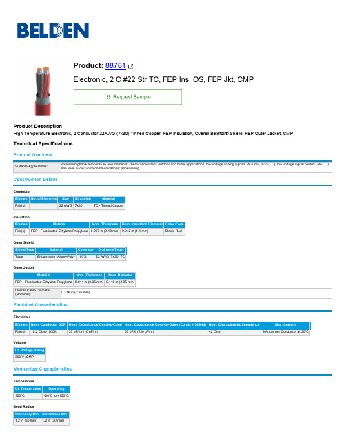
22 AWG (7x30) TC
Outer Jacket
Material
Nom. Thickness Nom. Diameter
FEP - Fluorinated Ethylene Propylene 0.014 in (0.36 mm) 0.116 in (2.95 mm)
Overall Cable Diameter (Nominal):
Temperature
UL Temperature Operating
150°C
-20°C to +150°C
Bend Radius Stationary Min. Installation Min. 1.2 in (30 mm) 1.2 in (30 mm)
Max. Pull Tension: Bulk Cable Weight:
History
Update and Revision:
Revision Number: 0.535 Revision Date: 01-20-2023
Part Numbers
Variants
Item #
Color Putup Type Length
UPC
Footnote
88761 002100 Red Reel
Max. Current
Pair(s) 18.2 Ohm/1000ft
35 pF/ft (110 pF/m)
67 pF/ft (220 pF/m)
42 Ohm
9 Amps per Conductor at 30ºC
Voltage UL Voltage Rating 300 V (CMP)
Mechanical Characteristics
FP6381A 资料完整版

S5 Package (SOT-23-5)
FB
VIN
5
4
1 23
EN GND LX
S6 Package (SOT-23-6)
FB PG VIN
6 54 1 23
EN GND LX
S8 Package (TSOT-23-5)
FB
VIN
5
4
1 23
Features
Low RDS(ON) for Internal Switch (Top/Bottom): 300/250mΩ
6
Voltage Feedback Input Pin. Connect FB and VOUT with a resistive voltage divider. This IC senses feedback voltage via FB and regulates it at 0.6V.
5
Open Drain Power Good Output Pin.
Undervoltage Lockout
Bias Supply
90ቤተ መጻሕፍቲ ባይዱ VREF
FB
EA
Compensation
VREF
Soft Start
Slope Compensation
COMP
Control Logic Current Limit
Logic
Control and
Driver Logic
1X
Oscillator
FP6381A-0.3-DEC-2013
2
fitipower integrated technology lnc.
FP6381A
Functional Pin Description
XC6385中文资料
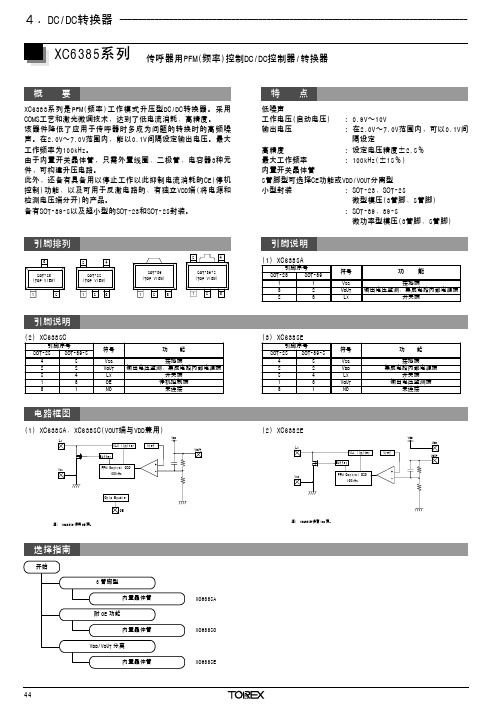
概 要
XC6383系列是PFM(频率)工作模式升压型DC/DC转换器。采用 COMS工艺和激光微调技术,达到了低电流消耗、高精度。 该器件降低了应用于传呼器时多成为问题的转换时的高频噪 声。在2.0V~7.0V范围内,能以0.1V间隔设定输出电压。最大 工作频率为100kHz。 由于内置开关晶体管,只需外置线圈、二极管、电容器3种元 件,可构建升压电路。 此外,还备有具备用以停止工作以此抑制电流消耗的CE(停机 控制)功能、以及可用于反激电路的、有独立VDD端(将电源和 检测电压端分开)的产品。 备有SOT-89-5以及超小型的SOT-23和SOT-25封装。
引脚排列
3
SOT-23 (TOP VIEW)
1
2
5
4
SOT-25 (TOP VIEW)
123
SOT-89 (TOP VIEW)
1
2
3
5
4
SOT-89-5 (TOP VIEW)
1
2
3
引脚说明
ቤተ መጻሕፍቲ ባይዱ
(2) XC6385C
引脚序号
SOT-25 SOT-89-5
4
5
2
2
5
4
1
3
3
1
符号
VSS VOUT LX CE NC
元器4件.交D易C/网DCw转ww换.c器ecb2_b__._c_o_m____________________________________________________________________________________
XC6385系列 传呼器用PFM(频率)控制DC/DC控制器/转换器
选择指南
开始
3 管脚型 内置晶体管
LOCTITE 638 RC BO50ML EN CH JP 安全技术说明书
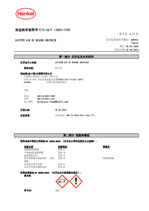
安全技术说明书根据GB/T 16483-2008第 1 页共 15 页LOCTITE 638 RC BO50ML EN/CH/JP安全技术说明书编号 : 450822V001.5修订: 16.09.2020发布日期: 12.04.2021化学品中文名称: LOCTITE 638 RC BO50ML EN/CH/JP推荐用途:粘合剂制造商/进口商/分销商代表公司汉高粘合剂科技(上海)有限公司中国(上海)自由贸易试验区张衡路928号2B(即1幢)105室201204 中国上海市浦东新区中国电话:+86-21-2891 8000传真:+86-21-2891 5137电子邮件: ***************************生效日期: 16.09.2020应急信息:应急电话:+86 21 2891 8311 (24小时)。
物质或混合物的分类根据GB 13690-2009 (化学品分类和危险性公示通则):危险分类危险类别靶器官皮肤腐蚀/刺激类别 2严重眼损伤/眼刺激类别 1皮肤敏化作用类别 1特异性靶器官系统毒性一次性接触类别 3呼吸道刺激急性危害水生环境类别 2对水生环境有慢性危害类别 3标签要素根据GB 15258-2009 (化学品安全标签编写规定):象形图信号词:危险安全技术说明书编号: 450822 V001.5LOCTITE 638 RC BO50ML EN/CH/JP第 2 页共 15 页危险性说明:H315造成皮肤刺激。
H317可能导致皮肤过敏反应H318造成严重眼损伤。
H335可能引起呼吸道刺激。
H401对水生生物有毒。
H412对水生生物有害并具有长期持续影响。
预防措施:P261避免吸入粉尘/烟/气体/烟雾/蒸气/喷雾。
P264处理后要彻底洗手P271只能在室外或通风良好之处使用。
P272受沾染的工作服不得带出工作场地。
P273避免释放到环境中。
P280戴防护手套,防护眼罩和防护面具。
TCN75A数字温度传感器中文数据手册「EasyDatasheet」
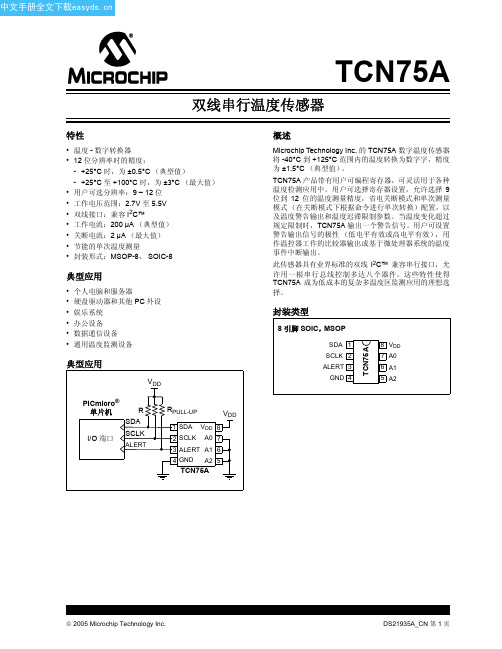
单位
°C 注 1 °C °C
°C/W °C/W
条件
2005 Microchip Technology Inc.
DS21935A_CN 第 3 页
中文手册全文下载
TCN75A
串行接口时序规范
电气规范:除非另有说明, VDD = 2.7V 至 5.5V, GND = 地, TA = -40°C 至 +125°C, CL = 80 pF,并且所有限制都 在高低电平的 50% 处测得。
参数
符号 最小值 典型值 最大值 单位
条件
电源电压 工作电压范围 工作电流 关断电流
上电复位 (POR)阀值 温度传感器精度 12 位分辨率时的精度:
TA = +25°C +25°C < TA ≤ +100°C -40°C < TA ≤ +125°C 内部 Σ-∆ ADC 转换时间: 9 位分辨率 10 位分辨率 11 位分辨率 12 位分辨率 警告输出 (漏极开路) 高电平电流
此传感器具有业界标准的双线 I2C™ 兼容串行接口,允 许用一根串行总线控制多达八个器件。这些特性使得 TCN75A 成为低成本的复杂多温度区监测应用的理想选 择。
封装类型
8 引脚 SOIC,MSOP
SDA 1 SCLK 2 ALERT 3
GND 4
TCN75A
8 VDD 7 A0 6 A1 5 A2
—
1.4
—
s 从 27°C (空气)升到 125°C (油槽)过程中,达 到 63% (89°C)的时间
DS21935A_CN 第 2 页
2005 Microchip Technology Inc.
中文手册全文下载
DC22.1111.111;DC22.2111.111;DC22.6111.111;DC22.4111.111;DC22.1121.111;中文规格书,Datasheet资料

- - - - differential mode _____ common mode
4A
6A
10 A
Medical version (M5)
1A
2A
4A
6A
10 A
Connectors
/
DC22
/pg06
Variants
Rated Current [A]
Terminal
Panel Thickness s
Material: Housing
1 - 10 A @ Ta 40 °C / 250 VAC; 50 Hz 1 - 10 A @ Ta 40 °C / 125 VAC; 60 Hz standard < 0.5 mA (250 V / 60 Hz) medical < 5 µA (250 V / 60 Hz) > 1.7 kVDC between L-N > 2.7 kVDC between L/N-PE Test voltage (2 sec) -25 °C to 85 °C 25/085/21 acc. to IEC 60068-1 from front side IP 40 acc. to IEC 60529 Suitable for appliances with protection class 1 acc. to IEC 61140 For PCB mounting ; Ground terminal: Quick connect terminals 6.3 x 0.8 mm angled to pin axis Screw: max 4 mm Mounting screw torque max 0.5 Nm Thermoplastic, black, UL 94V-0
C111340, 规格书,Datasheet 资料
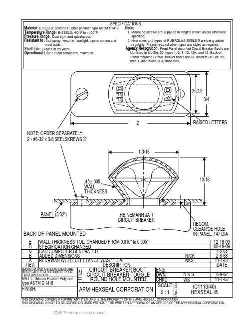
RECOM. CLEAR'CE HOLE IN PANEL .147 DIA 12-18-09 08-19-09 1-3-03 2-6-68 11-1-67 DATE 8-9-67 11-1-67
NICK NKS ENG. DWN. CHKD. N.K.S. WS
MAXIMUM AND MINIMUM MEASUREMENTS ARE STATED DIRECTLY ONБайду номын сангаасEACH DIMENSION.
21/32 3/4
2 NOTE: ORDER SEPARATELY 2 - #6-32 x 3/8 SEELSKREWS ® 1 3/16
RAISED LETTERS
.45±.005 WALL THICKNESS
13/16
PANEL (3/32")
HEINEMANN JA-1 CIRCUIT BREAKER
SPECIFICATIONS
Notes: 1. Mounting screws are supplied in lengths shown unless otherwise specified. 2. New sizes and types of RUBRGLAS-SEELS ® are being added regularly. Please request other types and styles as required. Agency Recognition : Front Panel mounted Circuit Breaker Boots are UL-listed to UL Std. 50, types 1, 2, 3, 12, 12K, and 13. Back-ofPanel mounted Circuit Breaker boots are UL-listed to UL Std. 50, type 1. Also meet CSA standards.
LT3756中文资料
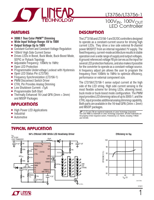
LDMQ
16-Lead (3mm × 3mm) Plastic QFN –40°C to 125°C
LT3756EUD-1#PBF
LT3756EUD-1#TRPBF LDMR
16-Lead (3mm × 3mm) Plastic QFN –40°C to 125°C
LT3756IUD-1#PBF
LT3756IUD-1#TRPBF
VC, VREF, SS, FB .........................................................3V
SYNC ..........................................................................8V RT ............................................................................1.5V SENSE......................................................................0.5V Operating Junction Temperature Range
LT, LTC and LTM are registered trademarks of Linear Technology Corporation. True Color PWM is a trademark of Linear Technology Corporation. All other trademarks are the property of their respective owners. Protected by U.S. Patents, including 7199560 and 7321203.
承担《XX国XX与新西兰XXXX电子电器产物及其部件

信息技术设备
照明电器
地址/邮编:XX市XX区大山子酒仙桥北路乙7号/100015
联系人:陈静、李华
电话:
传真:
e-mail:;
12
中国电子技术标设备
信息技术设备
地址/邮编:XX市XX区安定门东大街1号/100007
联系人:梁秀荣
电话:/
传真:
e—mail:
联系人:刘春浩
电话:,87237533/
传真:
e-mail:
2
中国家用电器研究院(中国家用电器检测所)
家用和类似用途电器
家用和类似用途固定式电器装置的开关(仅包括IEC60669标准检测能力)
家用及类似用途器具耦合器照明电器
地址/邮编:XX市XX区下斜街29号/100053
联系人:宫赤霄
电话:/
传真:
电动工具(仅包括电钻(含冲击电钻),电动螺丝刀和冲击扳手,电磨(仅包括角向磨光机、直向磨光机、模具电磨、带水源的磨光机、抛光机、盘式砂光机),砂光机(包括轨迹式砂光机、带式砂光机、自由摆动式砂光机),电圆锯、电锤(包括电镐),往复锯(包括曲线锯、刀锯),电刨产品检测能力)
家用和类似用途电器(仅包括家用电冰箱、食品冷冻箱和制冰机类,电风扇类,家用电动洗衣机/脱水机类,储水式电热水器类,室内加热器类,真空吸尘器类,皮肤及毛发护理器具类,电熨斗类,电烤箱类,家用厨房机械类,微波炉类,吸油烟机类,液体加热器类,电饭锅类产品检测能力)
家用和类似用途电器(仅包括电风扇类,储水式电热水器类,室内加热器类,真空吸尘器类,皮肤及毛发护理器具类,快热式电热水器类,电熨斗类,电烤箱类,家用厨房机械类,微波炉类,电灶、灶台、电烤炉类,吸油烟机类,液体加热器类,电饭锅类产品检测能力)
