(图文)Part8 - vCAC 6.0系列之创建和发布Blueprints
VC6.0与matlab7.0程序发布及一些问题

<matlab7.0 安装目录> \Extern\Include;
Tools—>Options—>Directories—>Show directories for: Library 添加
<matlab7.0 安装目录> \Extern\Lib\Win32\Microsoft\msvc60;
Tools—>Options—>Directories—>Show directories for: Library 添加
<MCR 安装目录>\MathWorks\MATLAB Component Runtime\v71\extern\lib\win32\microsoft\msvc60
四.警告:找不到JAVA库 Warning: Unable to find Java library:
*:\***\release\/sys\java\jre\win32\jre\bin\classic\jvm.dll
这个错误可见mathwork网站的解决方案,/support/solutions/data/1-ZITAA.html?product=CO&solution=1-ZITAA 具体原因是由于*:\***\release\目录下存在 mclmcrrt71.dll,mclmcr.dll,
启动matalb7.01,在命令窗口中输入 mex -setup 回车 按照提示,根据实际情况设置;
输入mbuild -setup 回车,按照提示,根据实际情况设置;
2 利用mcc 将Matlab函数转成DLL函数
在你要处理的m文件所在目录 输入 mcc -W cpplib:dllname -T link:lib filename.m
展讯开发环境配置

Make/Build环境使用手册Version:0.1.52009-10-21.spreadtrum.修订历史重要声明声明本文档中的任何内容受《中华人民XX国著作权法》的保护,所有 © 2006, 展讯通信XX,保留所有权利,但注明引用其他方的内容除外。
商标声明本文档中展讯通信XX的产品的所有商标是展讯通信XX专有,但注明属于其他公司拥有的商标除外。
在提及其他公司及其产品时将使用各自公司所拥有的商标,这种使用的目的仅限于引用。
不作保证声明展讯通信XX不对此文档中的任何内容作任何明示或暗示的陈述或保证,而且不对特定目的的适销性及适用性或者任何间接、特殊或连带的损失承担任何责任。
XX声明本文档(包括任何附件)包含的信息是XX信息。
接收人了解其获得的本文档是XX的,除用于规定的目的外不得用于任何目的,也不得将本文档泄露给任何第三方。
目录1说明62运行环境72.1编译环境及安装相关软件73编译架构84目录结构及关键脚本114.1make/build环境的关键目录结构114.2关键脚本124.2.1Makefile.rules124.2.2Makefile.modules134.2.3Makefile.third-party134.2.4Makefile.verify134.2.5Makefile134.2.6make.bat135基本命令145.1帮助145.2编译参数中 projectname 与项目编译脚本对应关系14 5.3编译整个项目[update]145.4重新编译整个项目[new]155.5清除所有编译结果[cleanall]155.6清除模块编译结果155.7编译模块155.8生成可执行文件155.9编译FDL/bootloader155.10编译NV155.11编译Resource165.12编译手机模拟器工程176其它命令206.1编译Logel工具206.2pclint 扫描206.3编译完成net send提醒功能206.4编译命令的简写206.5多线程编译206.6分布式编译216.7编译出错暂停216.8特别提醒217模块修改及项目定制227.1模块修改227.1.1模块目录结构调整227.1.2添加或删除文件227.1.3修改编译选项227.1.4新增模块237.2项目定制237.2.1创建全新的项目编译脚本237.2.2复制方式创建项目编译脚本237.2.3添加或删除模块247.2.4修改项目编译选项247.2.5客户发布及使用258第三方编译选项说明269相关使用技巧279.1查看log文件279.2makefile 编译过程中报错: No rule to make target ` XXX ', needed by `yyy'.27 9.3Makefile 中全局变量和转义宏的区分279.4Source Insight和ClearCase配置279.5鼠标右键命令行快捷方式设置309.6DOS下输入命令时用Tab键进行命令自动填充301 说明Make/Build环境中实现了项目开发和维护使用的GNU标准应用脚本,基于这些应用脚本和相关make工具,Make/Build环境可以完成项目全部代码的编译和二进制文件的生成,对其他一些需要的文件也可以在Make/Build环境中通过编译的方式产生,如fdl,bootloader,nv_parameter,resource等。
encounter很好的辅导资料

Invoke Cadence On-Line Document
1. 在terminal里执行 unix% /usr/cad/cadence/SOC/cur/tools/bin/cdnshelp & 如 果不输入完整路径而真接输入cdsdoc,则根据PATH设定的顺序不同可能会执 行到其它cadence软件的On-Line document。 2. 在Language上連点兩下,底下窗口列出LEF和DEF的文件, 再在LEF/DEF 5.6 Language Reference 上連点兩下,右边出现这份文件的内容。 在LEF Syntax上点兩下,应可看到所有LEF的语法說明,你可以再往下点找到详细的 LEF语法。 3. 回到Products页(现在可能被收起來了, 按一下Products展开),展开 SoC
Start SOC Encounter
5. 进入Lab-A lab unix% cd Lab-A 6. 这个Lab的设计档放在design_data目錄里, cell library的档案放在library目 錄里, 如果你是在学校里做这个design, 你必须从CIC提供tsmc.13 design kit 里找到这些档案. 7. 进入Lab2 unix% cd Lab2
Page 1 of 32
z
Lab1 On-Line Document { Logging in { Invoke Cadence On-Line Document { Lab2 System Startup Logging in Copy lab material Start SOC Encounter { Lab3 Design Import, floorplan Prepare Data Design Import Global Net Connect Specify Scan Chang Floorplan { Lab4 Powerplan Powerplan
C++6.0标准文件的创建(控制台应用程序)

C++标准文件的创建首先打开VC++6.0通过“文件——>新建”命令打开如下对话框,然后选择控制台应用程序,为工程起一个合适的名字后就可以点击确定进入下一步(保存位置可根据实际需要进行设置)。
这一步,我一般喜欢选择创建一个空的工程。
最后点击完成,会出现一个对工程骨架的说明,这个不用管,直接确定就可以了,这样一个工程就建好了。
但因为选择的是空工程,还需要添加自己需要的文件,包括头文件、源文件和资源文件。
但资源文件不是一个标准的c++工程所必须的。
头文件的内容一般是对类的定义和声明以及对成员函数的声明,而对函数的定义一般和主函数一样写在源文件中。
但并不是说要把主函数和对类的成员函数的定义写在同一个文件中,而是说在同一个分类下,都放在源文件的文件夹中。
类视图和文件视图则分别对应的查看工程中的所有类和文件。
之后可以通过“插入——>类”命令创建自己的自定义类。
为自己的类起一个名字,点击确定就可以了。
这时候在文件视图下就可以发现在源文件夹和头文件夹中出现了两个相同名字的文件,这就是你的自定义类的源文件和头文件了。
另外还可以通过另外一种方法添加单独的源文件或头文件。
通过“工程——>增加到工程——>新建”打开如下对话框。
附带一个例子:(三个文件)文件一:Person.h#pragma onceclass Person{public:Person(void);~Person(void);void set(char name[10],char sex[3],int age);char* getName();char* getSex();int getAge();private :char Name[10];char Sex[3];int Age;};文件二:Person.cpp#include"Person.h"#include<cstring>Person::Person(void){}Person::~Person(void){}void Person::set(char name[10],char sex[3],int age) {strcpy(Name,name);strcpy(Sex,sex);Age=age;}char* Person::getName(){return Name;}char* Person::getSex(){return Sex;}int Person::getAge(){return Age;}文件三:main.cpp#include<iostream>#include"Person.h"using namespace std;int main(){char name[10]="安燕朋";char sex[3]="男";int age=22;Person student;student.set (name,sex,age);cout<<student.getName ()<<student.getSex() <<student.getAge ();return 0;}需要说明的是以上附带文件的测试环境为VS2005,我也是个菜鸟,欢迎大家到我的空间留言交流学习。
vc6.0使用教程详解
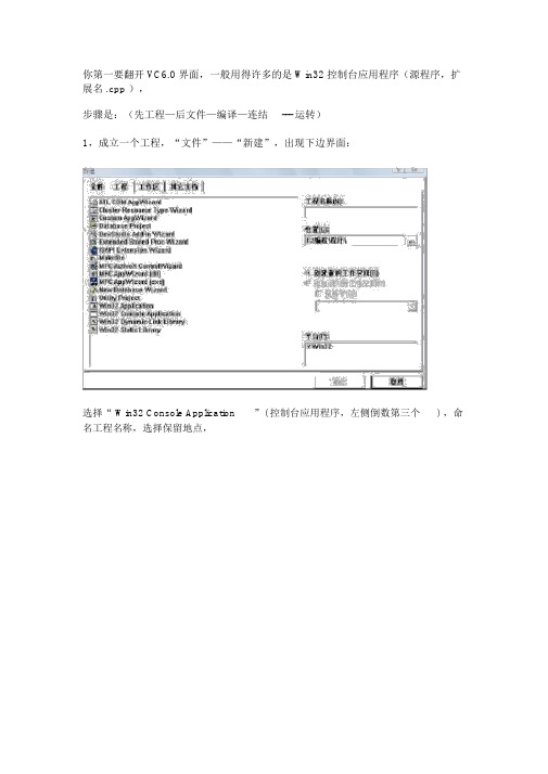
你第一要翻开 VC6.0 界面,一般用得许多的是 Win32 控制台应用程序(源程序,扩展名 .cpp ),步骤是:(先工程—后文件—编译—连结--- 运转)1,成立一个工程,“文件”——“新建”,出现下边界面:选择“ Win32 Console Application ”( 控制台应用程序,左侧倒数第三个) ,命名工程名称,选择保留地点,点击“确立”,进入下一步,看到以下提示界面:成立一个空工程,对应其余需要的你一能够成立其余工程;点击“达成” ,以后:显示你创立的工程的信息。
2,再在有一个的工程的条件下,我们再成立一个源文件;“文件”——“新建”(快捷键Ctri+N ),出现:成立源文件,选择“ C++ Source ”,一般都是成立这类文件的(合用在当文件中合用)假如要成立头文件的话,选择“ C/C++ Header File ”,( 合用在多文件工程中使用 ) 命名,文件名称,点击“确立”,以后:进入编写区,在主界面编写代码:以下编写完以后呢:能够按编译按钮调试程序,看看有没有错误,有的话更正,没有的话就能够再按连结按钮检查连结(多文件工程经常用,检查文件间能否正常连结),最后,点运转按钮,就能够运转了。
假如是您有代码如: cpp 文件,或 .h 文件,想增添都 VC6.0 里来测试的话,能够这样做:第一,要理解一下文件扩展名为: cpp 和.h文件扩充名是 .h, 代表的是头文件,一般是书写一些函数原型,以及一些在整个程序中常用到的构造体,屡次使用的函数说明,定义等等;文件扩充名为 ,cpp 的,是 C++中的源文件,也是最常用到的文件,每成立一个工程都要起码一个源文件(起码要有一个函数进口——主函数 main() ),包括了中心代码;成立与运转说明:(以VC 6.0 编译器为例,其余编译器近似)第一,翻开 VC 6.0 编译环境;在菜单栏——文件(的下拉菜单中选择“新建”),在弹出的选择窗口中,选择Win32 Console Application( 控制台应用程序 ) ,在填写工程名称,选择一个程序保留路径,点击“达成”,查察工程信息。
Noulds EthoVision 8.0软件快速入门中文版

主要步骤 ............................................................................ 17 手动记录行为 ..................................................................... 18 同时采集外部数据 .............................................................. 18
在 EthoVision XT 中,从 Help (帮助)菜单中选择 Video Tutorial (视频教程)。观看此教程,以了解如何在 EthoVision XT 8 中建立视频 跟踪研究项目。 在该程序的多个部分中还有一些简短视频教程可供观看。 可单击工具栏上的图标来观看这些教程。
处理 EthoVision 实验
有关详细信息,请参见样本实验 DVD 中的讲解 EthoVision XT 的样本实 验说明。
EthoVision XT 的主窗口。左边的 Experiment Explorer(实验浏览器)中包含三 个主要项目:Setup (设置)、Acquisition (采集)和 Analysis (分析)。右侧 的窗口显示在 Experiment Explorer (实验浏览器)中所单击项目的详细信息。
8 使数据可视化 ............................................................ 25
9 计算统计结果 ............................................................ 27
VC6.0简单绘图说明
第二章VC6.0简单绘图说明许多学编程的都是从C 语言开始入门的,而目前的现状是:有些学校以Turbo C 为环境讲C 语言,只是Turbo C 的环境实在太老了,复制粘贴都很不方便。
有些学校直接拿VC 来讲C 语言,因为VC 的编辑和调试环境都很优秀,并且VC 有适合教学的免费版本。
可惜在VC 下只能做一些文字性的练习题,想画条直线画个圆都很难,还要注册窗口类、建消息循环等等,初学者会受严重打击的。
初学编程想要绘图就得用TC,很是无奈。
还有计算机图形学,这门课程的重点是绘图算法,而不是Windows 编程。
所以,许多老师不得不用TC 教学,因为Windows 绘图太复杂了,会偏离教学的重点。
新的图形学的书有不少是用的OpenGL,可是门槛依然很高。
要给初学者一个简单的学习平台,就要VC的开发平台和TC的简单的绘图功能,于是就有了这个EasyX 库,我们需要在VC下下载安装EasyX库,下载地址:http:///。
下面是VC下简单绘图函数的基本说明。
1.系统支持操作系统版本:Windows 2000 及以上系统。
编译环境版本:Visual C++ 6.0 / 2008(x86 & x64) / 2010(x86 & x64)。
2.安装请先将下载的压缩包解压缩,然后执行Setup.hta,并跟随提示安装。
安装程序会检测已经安装的VC 版本,并根据选择将对应的.h 和.lib 文件安装至VC 的include 和lib 文件夹内。
安装程序不会修改注册表或者本机的任何文件。
如果需要手动安装,请根据下面的文件列表说明将安装包里的相关文件分别复制到VC 对应的include 和lib 文件夹内,或者将include 和lib 文件夹放到任意位置,然后修改VC 中的Lib 和Include 的引用路径。
3.卸载由于安装程序并不改写注册表,因此在“添加删除程序”中不会看到EasyX 的卸载项。
宏为世纪教育VC6.0上机指导

宏为世纪教育VC6.0上机指导实验目的:1、熟练掌握C语言在VC6.0编程环境下的操作2、运行简单的C程序,初步了解C源程序的特征实验内容:C语言源程序(后缀名为.c)可以在VC6.0或Turbo C2.0(简称TC2.0)等很多编译系统或集成环境中编译运行,但由于最新版2008年全国计算机等级考试(NCRE)将全面使用VC6.0上机环境,所以我们主要介绍VC6.0上机环境。
(如果你的电脑中没有安装VC6.0,在平时练习的时候完全可以使用TC2.0运行程序,最后考试的时候使用VC6.0就可以了,这对我们学习的效果一点影响都没有,事实上,使用TC2.0会比使用VC6.0少很多麻烦,具体TC2.0软件和使用说明可在下载)。
一、Microsoft Visual VC++6.0(简称VC++6.0或VC6.0)的简介和安装:现在常用的Visual C++6.0版本,虽然已有公司推出汉化版,但只是把菜单汉化了,并不是真正的中文版Visual C++,而且汉化的用语不准确,因此许多人都使用英文版。
如果计算机中未安装Visual C++6.0,则应先安装Visual C++6.0,Visual C++是Microsoft Visual Studio的一部分,因此需要找到Visual Studio的光盘,执行其中的setup.exe,并按屏幕上的提示进行安装即可。
安装结束后,在Windows的“开始”菜单的“程序”子菜单中就会出现Microsoft Visual Studio子菜单。
在需要使用Visual C++时,只需从电脑上选择“开始”->“程序”->Microsoft Visual Studio->Visual C++6.0(也可以从桌面快捷方式或其他方式进入)即可,此时屏幕上在短暂显示Visual C++6.0的版权页后,出现Visual C++6.0的主窗口,如下图所示,在Visual C++主窗口的顶部是Visual C++的主菜单栏。
bizhub 250 350印表机控制器操作指南说明书
歡迎歡迎感謝您購買本機。
bizhub 250和350配有一體式印表機控制器,使您能夠從個人電腦直接進行列印。
本快速指南說明了印表機控制器的列印功能、操作、使用以及安全注意事項。
為了確保本機的有效使用,請在使用之前仔細閱讀本說明書。
為了確保本機的安全使用,請在使用之前仔細閱讀操作手冊[複印操作]中的“安裝與操作注意事項”。
本快速指南所用的示意圖可能與實際型號有所不同。
Energy Star®作為ENERGY STAR®的合作夥伴,我們已確定本機符合關於節能的“ENERGY STAR®指導規範”。
什麼是ENERGY STAR®產品?ENERGY STAR®產品具有一個特性,在經過一段無活動時間後,它能自動切換到“節能模式”。
ENERGY STAR®產品利用能源的效率更高,可以幫助節省公共事業收費並有助於保護環境。
250/350x-1歡迎商標與版權-KONICA MINOLTA、KONICA MINOLTA 標識、以及 The essentials of imaging 是柯尼卡美能達控股有限公司的註冊商標。
-PageScope 與 bizhub 是柯尼卡美能達商用科技株式會社的註冊商標。
-Netscape Communications、Netscape Communications標識、Netscape Navigator、Netscape Communicator以及Netscape是NetscapeCommunications公司的商標。
-Novell及Novell NetWare是Novell有限公司的註冊商標。
-Microsoft、Windows、及Windows NT 是微軟公司的註冊商標。
-IBM 是國際商用機器有限公司的註冊商標。
-Apple、Macintosh與Mac 是蘋果電腦有限公司的註冊商標。
-Adobe、Adobe 標識、Acrobat、Acrobat 標識、PostScript、以及 PostScript 標識是Adobe系統有限公司的註冊商標或商標。
CY8CMBR3XXX_CapSense Design Guide(Chinese)
耐水性 .................................................................................................................................................................. 19
® ®
CY8CMBR3xxx CapSense 设计指南
®
文 档编号: 001-91599 版本**
2
目录
1.
简介 ................................................................................................................................................................................. 6 1.1 1.2 1.3 1.4 1.5 1.6 摘要 ....................................................................................................................................................................... 6 简介 ....................................................................................................................................................................... 6 CY8CMBR3xxx 系列特性概述 ............................................................................................................................... 7 CY8CMBR3xxx 系列的特性比较 ............................................................................................................................ 9 CY8CMBR3xxx CapSense 的系统概述 ............................................................................................................... 10 CapSense 设计流程............................................................................................................................................. 11
VC++_6.0_开发环境

Microsoft Visual C++ 6.0 控制台应用简介题目简介与任务分拆,部分可直接采用的代码片段、说明与提示;等等。
……,……。
下面的内容是,针对集成编程软件工具平台的使用、编程环境模式,即控制台应用过程的说明。
主要内容:0. Microsoft Visual C++简介1.创建一个新的C 语言的工程2.添加一个文件到一个空的工程中3.编写程序4.运行程序5.调试程序- 设置断点6.调试程序- 动态察看变量的值0. Microsoft Visual C++简介Microsoft Visual C++,(简称Visual C++、MSVC、VC++或VC)是微软公司的C++开发工具,具有集成开发环境,可支持基于C语言,C++ 以及C++/CLI 等编程语言的软件开发;特别是整合了微软视窗操作系统的应用程序设计接口(Windows API)、三维动画DirectX API、Microsoft MFC类库及Microsoft .NET 框架等。
当前最新的版本是Microsoft Visual C++ 2010。
根据本课程设计及前修课程《C语言程序设计》上机实验环节的情况,并结合当前全国计算机等级考试机试对开发环境的要求,本文针对Microsoft Visual C++ 6.0(以下简称VC6.0)开发环境下的控制台应用做简要介绍。
1.创建一个新的C 语言的工程1.1启动Microsoft Visual C++ 6.0启动VC6.0可以通过“开始”菜单,也可以通过桌面快捷方式等方式。
图1.1 VC6.0开发环境启动之后,我们看到的是空白的VC6.0开发环境截图如图1.1所示。
该截图是英文版的VC6.0,而中文版中的菜单、窗口与之一一对应。
跟大多数的Windows 应用程序一样,VC6.0最上面是菜单,然后是工具栏,中央是工作区,最下面一行是状态栏。
我们现在看到的工作区,左边是Workspace 窗口,右边是灰底的空白窗口。
在VC6.0中编写和运行示例程序的方法

在VC6.0中编写和运行示例程序的方法1. 启动VC 6.0,选择菜单File|New …,在打开的对话框中,选择“Win32 Console Application ”, 如下图所示。
输入项目名称之后按下“OK ”。
2. 在随后打开的对话框中选择“An empty project ”, 然后按下“Finish ”。
3. 在随后打开的“New project information”对话框中,按下“OK”。
4. 现在已建立了一个空白的控制台程序。
将示例程序的某个*.CPP文件和common.h复制到你的project所在的文件夹下。
5. 选择VC窗口的“File view”,右击“Source files”,在弹出的菜单中选择“Add Files to Folder”。
如下图所示。
6. 接下来指定示例程序的*.CPP文件,使之出现在“Source Files”下面。
7. 类似地,将示例程序中的Common.h文件加入到“Header Files”下面。
8. 现在可以编译、运行了。
9. 如果你在build时出现如下错误:Linking...LIBCD.lib(wincrt0.obj) : error LNK2001: unresolved external symbol _WinMain@16Debug/DuList.exe : fatal error LNK1120: 1 unresolved externals则说明编译连接时找不到程序入口(main函数),这是微软的问题,不是我们的错误。
解决的办法是:选择菜单Project | settings…,在打开的对话框中选择标签“Link”,在其中的“Project Options”编辑框中,找到“subsystem: windows”,将其改为“subsystem: console”,如下图所示,然后按下“OK”。
10. 重新编译、运行。
你可以在示例程序的基础上按习题要求编写程序,然后运行、调试直至成功。
MXView使用手册

Moxa 中国 (上海办公室)
Toll-free: 800-820-5036
Tel:
+86-21-5258-9955
Fax:
+86-21-5258-5505
Moxa 亚太区
Tel:
+886-2-8919-1230
Fax:
+886-2-8919-1231
目录
1. 重要特性 ................................................................................................................................................... 1-1 基于 Web 运行 ...................................................................................................................................... 1-2 自动搜索与拓扑结构可视化 .................................................................................................................. 1-2 事件管理 ............................................................................................................................................... 1-2 配置与固件管理 .................................................................................................................................... 1-2 流量监控 ............................................................................................................................................... 1-2
OCS-Web 使用说明书
QUICK GUIDE OCS-Web For Scania suppliers – Long Term Supplier´s declarations (Country of Origin)ContentPoint Description Page1-3 Log on to OCS-Web................................................................................... 2-3 4-6 Open the document for the Long Term Supplier´s declaration.. (4)7 Part details and explanation to the columns (5)8 Declare Country of Origin part by part (6)9 Declare the same Country of Origin for several parts (7)10-11 Submit/Send/Approve your Long Term Supplier´s declaration...................................7-812 Corrections (8)13 See/print the Long Term Supplier´s declaration........................................................9-10 More information and details are to be found in MIC User guides, just click on the question mark at the upright corner;1. Click on the link in the e-mail that takes you to SSP (Scania Supplier Portal):2a. Click on the log in icon at the top right corner of the screen;2.b Now you enter your user id and password:3. Once you are logged in, click on the application (OCS-WEB) to enter the application.4. You are now in the application! Select 01/01 Scania SE (Manual) :(This happen the first time you access OCS, this will be default in the future.)5. Double click on Documents on the left side:6. Double click on the document (the marked record in the middle):7. All your active parts, provided to Scania will now be visible!(if the view is limited on your screen , so you don´t see the parts -just hide the above part by clicking on the heading Document and Supplier Information) : Or hold down the “CTRL” key and press once the “-“ key.This will reduce the size of the screen.99999TEST COMPANYSort by clicking on the column heading you wish to sort on, for example – Part description.Explanation to the columns (the yellow-marked fields are mandatory to fill in):Agreement : EUALL – cover all agreements that the EU has entered with different countries.Part number: Your part number at ScaniaPart Description: Part description within ScaniaTariff code: the code that Scania has inserted in Scania’s system.Sup Part.No: You have the option to insert your internal part number here:Supplier Tariff number: If you don´t agree with the Scania’s tariff you have the option to insert your tariff code in However – this is optional!CoO – Country of OriginPreferential Status – All items are 35-UNKNOWN when entering first time. If you select an European country under CoO – status will change to 01-CERTIFIED. You can always change to any of these: 35-UNKNOWN, 50-NOT CERTIFIED. Please note that you are not allowed to approve a part with 35-UNKNOWN status. If you are uncertain, please always use 50-NOT CERTIFIED.8. Declare Country of Origin and preferential status, part by part:Mark the record and choose Country by clicking in the box under “Country of Origin”. You can either typ in the ISO 2 letter code for the country or use the magnifying glass to get a popup window if you do not know the code for the country in quetsion. Please not that only the two letter country code is accepted.Select “Country of Origin” from the window that pops up. You can insert the first letter in the Country to quickly scroll down. Double-click on the selected Country and it will be inserted on the part selected..9. Declare “Country of Origin” and “preferential status” for several parts that will have the same Country:Press Ctrl button and mark the parts you want to select, one by one, or if you have sorted on Description and for example want to select all “HOSES” , press Shift and the first and last record of part HOSE and all between these will be part of your scoop.Apply to selected / Apply changes and save.There are several options to sort and declare in the user guides in MIC!10. Approve/send your Long Term Supplier´s declaration when you are ready with your parts by clicking on the Approve-button:11. Declare the validity period by backdate 1 year.This is possible with the new UCC. The valid to date will automatically set 2019-12-31 (you can change if you want). Insert your name, position and place and finally click on the Accept-button:Your Long Terms Supplier´s declaration is now submitted to Scania – thanks!This procedure will then re-occur when the LTSD expires, before issuing a new document with the parts the system will check to ensure the parts has been delivered during the previous 12 month period. This will reduce any parts that you have stopped to deliver due to expired or replaced orders. If you start providing new parts during the period you will receive separate requests for these items. They will then be solicited in the same scope as the other parts.12. If you want to change/correct data you have provided – just contact Scania’s Customs department :****************** and we will revoke the declaration so you can work with it again. Also state your supplier number in the subject!13. How to view the Long Term Supplier´s declaration that you have submitted:Click on Document, select Print and click on the text for download:The Long Term Supplier´s declaration will be expressed and you can print it if you want.Note that you don’t have to send it to Scania! The electronically provided declaration is sufficient.Sida 11 (11)。
Lodop6.0技术手册
WEB打印控件Lodop技术手册Ver 6.0.5.6Email: gungho999@QQ: 932131686梦泰尔软件工作室MTSoftware(CN)目录一、概述 (3)二、系统文件 (4)install_lodop.exe (4)LodopFuncs.js (5)三、控件参数 (6)Caption (6)Color (7)Border (7)四、功能函数 (7)1、基本函数 (7)VERSION (7)PRINT_INIT (7)SET_PRINT_PAGESIZE (8)ADD_PRINT_HTM (9)ADD_PRINT_TABLE (10)ADD_PRINT_URL (11)ADD_PRINT_TEXT (12)ADD_PRINT_IMAGE (13)ADD_PRINT_RECT (13)ADD_PRINT_ELLIPSE (14)ADD_PRINT_LINE (15)ADD_PRINT_BARCODE (16)ADD_PRINT_CHART (17)SET_PRINT_STYLE (18)NEWPAGE (19)PREVIEW (20)PRINT (20)PRINT_SETUP (20)PRINT_DESIGN (21)GET_PRINTER_COUNT (21)GET_PRINTER_NAME (21)SET_PRINTER_INDEX (21)SELECT_PRINTER (22)SET_SHOW_MODE (22)SET_PRINT_MODE (24)SET_PREVIEW_WINDOW (25)ADD_PRINT_SETUP_BKIMG (26)SEND_PRINT_RAWDA TA (26)WRITE_PORT_DA TA (27)READ_PORT_DA TA (27)GET_PRINT_INIFFNAME (27)GET_PAGESIZES_LIST (28)WRITE_FILE_TEXT (28)GET_FILE_TEXT (29)GET_FILE_TIME (29)IS_FILE_EXIST (29)GET_SYSTEM_INFO (30)GET_V ALUE (30)FORMAT (33)GET_DIALOG_V ALUE (34)2、扩展函数 (35)PRINT_INITA (35)ADD_PRINT_HTML (36)ADD_PRINT_TBURL (36)ADD_PRINT_TEXTA (36)SET_PRINT_STYLEA (37)SA VE_TO_FILE (40)SET_SA VE_MODE (40)ADD_PRINT_SHAPE (42)SET_PRINTER_INDEXA (43)NEWPAGEA (43)PREVIEW A (43)PREVIEWB (44)PRINTA (44)PRINTB (44)SHOW_CHART (44)DO_ACTION (45)SET_LICENSES (46)五、软件使用权注册 (46)CompanyName (46)License (47)LicenseA (47)LicenseB (47)六、打印维护和打印设计 (47)七、使用样例 (47)八、计量单位 (49)一、概述Lodop是一款专业的WEB打印控件,其设计目标是简单易用、功能足够强大,开创WEB 打印开发的新局面。
NVIDIA HPC SDK Release Notes Version 20.11说明书
RN-09976-001-V20.11 | November 2020TABLE OF CONTENTS Chapter 1. What's New (1)Chapter 2. Release Component Versions (2)Chapter 3. Supported Platforms (4)3.1. Platform Requirements for the HPC SDK (4)3.2. Supported CUDA T oolkit Versions (5)Chapter 4. Known Limitations (6)Chapter 5. Deprecations (7)LIST OF TABLEST able 1 HPC SDK Release Components (2)T able 2 HPC SDK Platform Requirements (4)Welcome to the 20.11 release of the NVIDIA HPC SDK, a comprehensive suite of compilers and libraries enabling developers to program the entire HPC platform, from the GPU foundation to the CPU and out through the interconnect.Key features that are new in the 20.11 release of the NVIDIA HPC SDK for Linux include:‣Beta support of a subset of OpenMP target offload features for NVIDIA GPUs on x86-based systems can be enabled in NVC++, NVC, and NVFORTRAN with-mp=gpu.‣NVFORTRAN accelerates the DO CONCURRENT construct to NVIDIA GPUs by default when enabled via the -stdpar option.‣Use the nvlamath Fortran library to access GPU-accelerated BLAS routines using the standard BLAS interfaces.‣The NVIDIA HPC SDK now supports version 11.1 of the CUDA toolchain.‣HPC SDK library and developer tool components have been updated to their newest versions.‣RPM packages for the Suse Linux Enterprise Server operating system are now available as download options.‣The default C++ Standard version for NVC++ is C++11.‣ A number of new command-line options have been implemented for HPC SDK compilers to increase compatibility with GCC:‣-f[-no]exceptions - Enable[/disable] exception handling‣-x - Specify the language for any following input files, instead of letting the compiler choose based on suffix. Turn off with -x none.‣-Wshadow - Issue a warning whenever a variable hides another variable‣-Wstrict-prototypes - C only. Warn if a function is declared or defined without specifying the argument types‣-Wno-long-long - Suppress warnings about long long being nonstandard‣-Wundef - Warn about using uninitialized variables‣-fpie - Generates position independent executable. Implies -pieThe NVIDIA HPC SDK 20.11 release contains the following versions of each component: T able 1 HPC SDK Release ComponentsRelease Component Versions3.1. Platform Requirements for the HPC SDK T able 2 HPC SDK Platform RequirementsSupported Platforms3.2. Supported CUDA T oolkit VersionsThe NVIDIA HPC SDK uses elements of the CUDA toolchain when building programs for execution with NVIDIA GPUs. Every HPC SDK installation package puts the required CUDA components into an installation directory called [install-prefix]/ [arch]/[nvhpc-version]/cuda.An NVIDIA CUDA GPU device driver must be installed on a system with a GPU before you can run a program compiled for the GPU on that system. The NVIDIA HPC SDK does not contain CUDA Drivers. You must download and install the appropriate CUDA Driver from NVIDIA , including the CUDA Compatibility Platform if that is required. The nvaccelinfo tool prints the CUDA Driver version as its first line of output. You can use it to find out which version of the CUDA Driver is installed on your system. The NVIDIA HPC SDK 20.11 includes stand-alone support for the following CUDA toolchain versions:‣CUDA 10.2‣CUDA 11.0‣CUDA 11.1See the NVIDIA HPC Compilers User Guide for information about using the HPC SDK Fortran, C++ and C compilers with alternative versions of the CUDA toolchain.‣ A known issue with CUDA 11.1, GNU toolchain versions 4.x, and the NVHPC compiler option -gpu=time may cause applications built with -gpu=time to crash at runtime.‣When compiling for Skylake Core or Skylake Xeon processors, it is recommended that the target processor compiler option -tp skylake is specified. Specifying -tpskylake at link time is optional.‣The cuda-gdb debugger is included in this release. Currently, Fortran arrays with non-constant bounds are not handled correctly and querying values willyield incorrect results. Stepping through cuda-fortran and OpenACC kernels ispartially supported, but incorrect line numbers are displayed. For additional general limitations with cuda-gdb, please refer to its documentation.‣When using -stdpar to accelerate C++ parallel algorithms, the algorithm calls cannot include virtual function calls or function calls through a function pointer, cannot use C++ exceptions, can only dereference pointers that point to the heap, and must use random access iterators (raw pointers as iterators work best).‣The Open MPI 4.0.5 build with UCX 1.9.0 is a beta feature in the NVIDIA HPC SDK20.11. It is built with support for MOFED 5.0; users on systems using earlier MOFEDversions may encounter compatibility issues.‣Support for the CUDA 10.1 toolchain has been dropped from the NVIDIA HPC SDK version 20.11; CUDA toolchains 10.2, 11.0 and 11.1 are now supported.‣Support for the KNL architecture of multicore CPUs in the NVIDIA HPC SDK will be deprecated in the upcoming 21.1 release.‣GCC 4.8 is the minimum required version for the NVIDIA HPC SDK 20.11.‣The NVIDIA HPC SDK will discontinue support for the Ubuntu operating system on ppc64le architecture systems starting with the upcoming 21.1 release.NVIDIA HPC SDK Release Notes Version 20.11 | 7NoticeALL NVIDIA DESIGN SPECIFICATIONS, REFERENCE BOARDS, FILES, DRAWINGS, DIAGNOSTICS, LISTS, AND OTHER DOCUMENTS (TOGETHER AND SEPARATEL Y, "MATERIALS") ARE BEING PROVIDED "AS IS." NVIDIA MAKES NO WARRANTIES, EXPRESSED, IMPLIED, STATUTORY, OR OTHERWISE WITH RESPECT TO THE MATERIALS, AND EXPRESSL Y DISCLAIMS ALL IMPLIED WARRANTIES OF NONINFRINGEMENT, MERCHANTABILITY, AND FITNESS FOR A PARTICULAR PURPOSE.Information furnished is believed to be accurate and reliable. However, NVIDIA Corporation assumes no responsibility for the consequences of use of such information or for any infringement of patents or other rights of third parties that may result from its use. No license is granted by implication of otherwise under any patent rights of NVIDIA Corporation. Specifications mentioned in this publication are subject to change without notice. This publication supersedes and replaces all other information previously supplied. NVIDIA Corporation products are not authorized as critical components in life support devices or systems without express written approval of NVIDIA Corporation.TrademarksNVIDIA, the NVIDIA logo, CUDA, CUDA-X, GPUDirect, HPC SDK, NGC, NVIDIA Volta, NVIDIA DGX, NVIDIA Nsight, NVLink, NVSwitch, and T esla are trademarks and/ or registered trademarks of NVIDIA Corporation in the U.S. and other countries. Other company and product names may be trademarks of the respective companies with which they are associated.Copyright© 2013–2020 NVIDIA Corporation. All rights reserved.NVIDIA HPC SDK。
MPC860 Board Design Checklist说明书

™M P C 860 B o a r d D e s i g n © Motorola Inc., 1998. All rights reserved.A p p l i c a t i o n N o t eApplication NoteMPC860 Board Design ChecklistNetcomm Applications Freescale , Austin, TexasIntroductionWhen integrating MPC8xx family members into an application, it may be helpful to go through the following design checklist. This checklist outlines a number of common problems with respective solutions that have been found while debugging real MPC860 applications.ChecklistVersion, MaskThe first version of the MPC860 was called rev 0. Metal fixes were made to this version to create versions such as rev 0.1. The first full layer change was revision A. Subsequent metal fixes add numbers to the revision, such as A.2.F r e e s c a l e S e m i c o n d u c t o r , IFor More Information On This ProductGo to: n c .© Freescale Semiconductor, Inc., 2004. All rights reserved.2Choosing Oscillators versus CrystalsIf you can afford the power dissipation of using an oscillator rather than a crystal, choose an oscillator. Crystal circuits must often be tweeked after the die goes through a geometry shrink.Using both Oscillators and CrystalsCrystal oscillators and crystals can be used together on the MPC860, however do not use the crystal on the EXTAL and XTAL pins and leave the oscillator free-running into the EXTCLK pin as this will cause excessive jitter. Rather, externally gate the clock of the oscillator to the EXTCLK pin while the crystal is in use. It’s good design practice that if you’re not using a crystal, ground the EXTAL pin.Clock Circuit LayoutLocate the crystal within 0.5 inches of the MPC8xx. The closer the better. The XFC capacitor should be physically as close as possible to the MPC8xx as well.VDDsyn FilterUse a LC filter on the VDDsyn pin instead of a RC filter. Please refer to the MPC860ADS schematic for a good example of a proper circuit.5 Volt Friendly SignalsAlthough the MPC8xx does support 5V inputs, please note that EXTAL and EXTCLK are not 5 Volt friendly inputs. Inputs on those signals are limited to 3.3V.Power Supply 2.2V ConfusionConnect 3.3V to the internal logic VCC pins (called VDDL) and all other power pins on the MPC8xx and not 2.2V. The use of 2.2V on VDDL was illustrated in one of the example user manual drawings, but is only allowed if a special version of the MPC8xx is purchased. At the time of writing this document, this special 2.2V version had not been introduced, so be sure to check with your local Freescale representative for availability, if this mode is required.Memory, DRAMNot all DRAM SIMMs are created equal. With Freescale SIMMs the signal integrity on the DRAMcontrol and address lines look good. With other manufacturers, series damping resistors need to be used. The MPC860ADS board was designed for Freescale SIMMs, and therefore does not show series damping resistors.F r e e s c a l e S e m i c o n d u c t o r , IFor More Information On This Product,Go to: n c .3Memory, DRAM, External MasterIf an external master device is accessing DRAM using the MPC8xx memory controller, the burst address pins (BADDR(28:30)) on the MPC8xx should be connected through the multiplexer, and not directly to the DRAM.How Many Layer Board?It is recommended to use one ground plane, one 3.3V VCC plane, and one 5.0V VCC plane (if 5V parts exist in the system). In addition at least four signal planes would normally be used to ensure easy routing to/from the MPC860.Analog Power SupplyThe MPC860ADS board design pays particular attention to the power planes in the area of the PLL power. The VDDsyn pin is routed to a via that punches down to a mini plane (really a peninsula on asignal layer) which is decoupled from VSSsyn with 10UF and 0.1UF parallel caps and also attaches to the 3.3 Volt plane through a 8.2mH inductor. The 3.3 and 5 volt planes have a keepout in the PLL power area. Separate the PLL VSSsyn from Global ground by means of a split in the plane with a connection point as close to the supply as possible. On other layers, signals are kept out of this area. Also, the PLL loop filter and decoupling caps should be placed as close to the MPC8xx as possible.Pullups on the Data BusPutting pullups on the Data Bus has implications on the initial configuration of the MPC8xx, since there is a mode whereby the part could sample the data bus during reset to determine its initial configuration. If you choose to put pullups on the data bus, make sure that the RSTCONF* pin is tied high, otherwise the default MPC8xx configuration values will be overwritten with ones from the pullups on the data bus. Alternatively, you can put pullups on the data bus (for the purpose of using them as bus keeps), if you drive all of the configuration pins actively high or low (as appropriate) during reset, as described below. The pullups can be terminated to either 5 or 3.3 volts and the value is left up to the designer.Hard Reset Configuration Word PinsThe data bus is sampled at reset to determine the initial configuration of the MPC8xx if the RSTCONF* pin is tied low. Ensure that the correct values are driven to the bus during the PORESET and HRESET periods. For any data pins that the user wishes to configure as 1’s (i.e. where the default configuration is not appropriate), do not expect pullups to be sufficient. Use active drivers to drive 1’s and 0’s if pullups are already being used on the data bus. The drivers should then be disabled following reset.Powerup Reset CircuitThere is no power up detector on the MPC8xx like there was on the 68360. To construct a simple circuit, hang a diode, cap and resistor network on PORESET line. A more robust (expensive) solution is to use a power on reset chip monitoring the power plane. Hard reset is a bidirectional signal and if used, needs to be driven with an open collector (open drain) device. Diodes should be used on the reset inputs to causeF r e e s c a l e S e m i c o n d u c t o r , IFor More Information On This Product,Go to: n c .4sharp transistions of those signals. The 860ADS board has an excellent treatment of the reset circuit, and should be followed as a guide.MPC860 Driving SRESET*The MPC8xx can drive the soft reset pin (SRESET*) as an output. It is driven by the MPC8xx any time that the PORESET* lines or the HRESET* line is asserted and also if a RESET command is delivered to the debug port.So You Need a Halt Signal?The MPC860 does not support a Halt signal. One suggestion we can make for board designers that have to have one, is to monitor the AT3-0 pins for an absence of activity.MODCK PinsThe MODCK pins become outputs after reset. To configure them, drive them with three state buffers enabled with HRESET*. Although MODCK is latched on rising edge of PORESET*, this is a slow edge so use HRESET* as the enable.Byte Lane for Boot EPROMIf eight bit wide memory/EPROM is used, attach the device to byte lane zero (D0-D7). Note that in PowerPC terminology, D0-D7 is the highest order byte lane on the data bus, and D0 is the highest order pin of that byte lane. D0-D7 corresponds to write enable 0 (WE0*) and Byte Select A or B 0 (e.g. BS_A0*).D0-D7 --> WE0* --> BS_B0* or BS_A0*D15-D8 --> WE1* --> BS_B1* or BS_A1*D23-D16 --> WE2* --> BS_B2* or BS_A2*D31-D24 --> WE3* --> BS_B3* or BS_A3*Highest order data pin: D0. Lowest order data pin: D31.Address PinsThe highest order address pin is A0. The lowest order address pin is A31. Check that the MSB (0) and LSB (31) are correctly connected. In a byte access, all 32 address pins are valid. In a 32-bit word access, only the upper 30 address pins are used (A0-29). A30 and A31 should both be zero.F r e e s c a l e S e m i c o n d u c t o r , IFor More Information On This Product,Go to: n c .5Address/Data NomenclatureWe recommend that you build your schematics in accordance with the PowerPC terminology. If you try to "rename" your address or data bus pins to make them 68K friendly (e.g. by renaming A0 to be A31), you will probably end up with mistakes on your board design.Chip Select Double DriveIt is possible to get more drive capability on CS2* and CS3* by having these signals output on 2 pins each. CS2* can be driven on the normal CS2* pin and GPL_A2*. CS3* can be driven on the normal CS3* pin and also GPL_A3*. Note that the CS* pins can also be used as RAS* lines, where drive capability often is critical in gaining the last nanosecond from the memory system. The double drive capability is programmed in the SIUMCR.Be Careful of R/W*A R/W* pin is provided on the chip, but its timing is not appropriate for all memory types. Remember that the R/W* timing is fixed, and the WE0-3* signals are usually a better choice. If the WE0-3* signal timing is not suitable, the more flexible UPM machine of the memory controller can be used to give precise timings on these signals.Put a 10-pin Header for the Development Port on Your BoardThe Development Port section of the user’s manual describes a 10-pin header that should be included on your board. Physically locate the 10 pin connector as close as possible to the processor to minimize trace length and cross coupling of noise onto the BDM signals. Do not run high speed clocks or signals adjacent to the BDM communication signals.When your boards arrive, you can begin initial testing via this port. The MPC860ADS board describes a feature whereby you can connect your 10-pin header to another 10-pin header on our ADS board. By connecting our ADS board to a PC, you can use our PC hosted debugger to begin to manipulate registers on the target board, just as you would on our ADS board. (Remember that the MPC8xx device on the ADS board must be removed for this mode ofoperation, and use the shortest possible cable between the ADS and your target). In addition, other third-party tools use this 10-pin header for their debugger capability.Debug Port InterfaceThe DSDI and DSCK pins are configured during reset to select certain modes of the development port system interface. If the user wishes to pull the DSCK pin low, then a 1Kohm pulldown should be used to make sure that low logic levels are recognized on all versions of the MPC8xx. DSDI should have a pullup to be on the safe side ( there is an internal pullup ). For the TA*, TEA* and BB* signal pins, use a 1k ohm pull-up resistor. If not you will get erratic operation.F r e e s c a l e S e m i c o n d u c t o r , IFor More Information On This Product,Go to: n c .6PCMCIA Buffers Not NeededAlthough the MPC8xx manual shows buffers in the PCMCIA design example, it is noted that such buffers on the address or data bus are only required if the address or data bus is heavily loaded, a 2 PCMCIA slot system is designed, or the board requires protection from hot plug-in of PCMCIA cards.IDMA, Memory-to-MemoryIf the user desires to use the IDMA in memory-to-memory mode, the DREQ* pin must be asserted. It is possible to ground the pin or use a parallel I/O pin to selectively enable the DREQ* function. Using the parallel I/O pin is preferable, to save the added overhead of the CPM RISC polling the IDMA buffer descriptors to see if the valid bit has been set.Port Pins, PullupsThe parallel port pins on the MPC860 do not have internal pullups or pulldowns. Unused parallel I/O pins may be configured as outputs after reset and left unconnected.Unused Input PinsUnused inputs should be tied high or low, but not left floating. Unused inputs may be tied directly to VCC or GND or through pullups or pulldowns to VCC or GND. For most pins, VCC can be either 3.3V or 5.0V.Unused Output PinsUnused output pins may be left unconnected.Erratic device operation following power upEnsure the TRST signal is connected as recommended in the rev. 1 version of the users manual as follows:If both the TAP (Test Access Port) and low power mode are NEVER used, connect TRST to ground. If the TAP or low power mode is used, connect TRST to PORESET. If power down mode ( the lowest power mode, where Vddh is disabled) is used, connect TRST to PORESET through a diode ( anode to TRST, cathode to PORESET). Do NOT connect TRST to HRESET as was previously recommended in certain documentation.Additional information on these areas is detailed in the Rev.1 version of he MPC860 Users Manual (UM). Please review sections 13.3 and 13.4 for full details.F r e e s c a l e S e m i c o n d u c t o r , IFor More Information On This Product,Go to: n c .7Controlling Excessive Rise Time on Negation of PORESET*To control excessive rise time on negation of PORESET* with an emulator installed, pullup the PORESET* line with a 1-K ohm pullup resistor.Using an 860T or 860EN:Locate the processor and ethernet controller as physically close together as is feasible. Provide for a series resistor option to fine tune clock ringing on RCLK and TCLK.UPM Design Hint When Using an EmulatorIt may be necessary to change UPM values when using a non-DPI ( Debug Port Interface ) connection method because of the impedance impact of installing an emulator probe or other line loading device into a target.Easier Testing/Debugging HintWherever possible place pads on the opposite side of the board from the processor for a possible future mirror probe connection.MPC850 and MPC823 external mastersThe 850 and 823 have only 26 externally visible address bits. Therefore, external masters should only address the range from hex 0000 0000 to x3FF FFFF if the external master uses the memory controller or any of it’s functions on the 850/823. The bits from an external master will be seen as 0’s by the memory controller. Internally the address bits are present and can be addressed for MMU and cache functions from the PPC core.CLKOUT SignalThe drive capability of the CLKOUT signal is modest. If necessary, use a clock driver/distribution device to redrive this signal. The MPC974 ,for example, can be configured as a ( near ) zero delay buffer.PLLLoop filter values require careful selection, and placement. Power Supply decoupling for the PLL requires attention as well.Chip Select 0Ensure that CS0 is connected to the boot memory device.F r e e s c a l e S e m i c o n d u c t o r , IFor More Information On This Product,Go to: n c .Using FLASH DevicesEnsure the correct FLASH bit ordering for the correct programming algorithm is connected.HRESET*, SRESET*, PORESET*, and TA* SignalsProvide low resistance value pull-ups (1K to 4.7 K) on the following signals: HRESET*, SRESET*, PORESET*, and TA*.F r e e s c a l e S e m i c o n d u c t o r , IFor More Information On This Product,Go to: n c .Information in this document is provided solely to enable system and software implementers to use Freescale Semiconductor products. There are no express or implied copyright licenses granted hereunder to design or fabricate any integrated circuits or integrated circuits based on the information in this document.Freescale Semiconductor reserves the right to make changes without further notice to any products herein. Freescale Semiconductor makes no warranty, representation or guarantee regarding the suitability of its products for any particular purpose, nor does Freescale Semiconductor assume any liability arising out of the application or use of any product or circuit, and specifically disclaims any and all liability, including without limitation consequential or incidental damages. “Typical” parameters which may be provided in Freescale Semiconductor data sheets and/or specifications can and do vary in different applications and actual performance may vary over time. All operating parameters, including “Typicals” must be validated for each customer application by customer’s technical experts. Freescale Semiconductor does not convey any license under its patent rights nor the rights of others. Freescale Semiconductor products are not designed, intended, or authorized for use as components in systems intended for surgical implant into the body, or other applications intended to support or sustain life, or for any other application in which the failure of the Freescale Semiconductor product could create a situation where personal injury or death may occur. Should Buyer purchase or use Freescale Semiconductor products for any such unintended or unauthorized application, Buyer shall indemnify and hold Freescale Semiconductor and its officers, employees, subsidiaries, affiliates, and distributors harmless against all claims, costs, damages, and expenses, and reasonable attorney fees arising out of, directly or indirectly, any claim of personal injury or death associated with such unintended or unauthorized use, even if such claim alleges that Freescale Semiconductor was negligent regarding the design or manufacture of the part.How to Reach Us:Home Page:E-mail:*********************USA/Europe or Locations Not Listed: Freescale SemiconductorTechnical Information Center, CH370 1300 N. Alma School Road Chandler, Arizona 85224+1-800-521-6274 or +1-480-768-2130 *********************Europe, Middle East, and Africa:Freescale Halbleiter Deutschland GmbH Technical Information Center Schatzbogen 781829 Muenchen, Germany +44 1296 380 456 (English) +46 8 52200080 (English) +49 89 92103 559 (German) +33 1 69 35 48 48 (French) *********************Japan:Freescale Semiconductor Japan Ltd. Headquarters ARCO Tower 15F1-8-1, Shimo-Meguro, Meguro-ku, Tokyo 153-0064 Japan0120 191014 or +81 3 5437 9125 ***************************Asia/Pacific:Freescale Semiconductor Hong Kong Ltd. Technical Information Center 2 Dai King StreetTai Po Industrial Estate Tai Po, N.T., Hong Kong +800 2666 8080**************************For Literature Requests Only:Freescale Semiconductor Literature Distribution Center P.O. Box 5405Denver, Colorado 802171-800-441-2447 or 303-675-2140 Fax: 303-675-2150*********************************************。
C++_Builder6.0简易实例教程
Borland C++Builder 6.0教程Borland C++Bilder 6.0是Interprise(Borland)公司推出的基于C++ 语言的快速应用程序开发(Rapid Application Development,RAD)工具,它是最先进的开发应用程序的组件思想和面向对象的高效语言C++融合的产物。
C++Builder 充分利用了已经发展成熟的Delphi 的可视化组件库(Visual Component Library,VCL),吸收了Borland C++ 6.0 这个优秀编译器的诸多优点。
C++Builder 结合了先进的基于组件的程序设计技术,成熟的可视化组件库和优秀编译器,调试器。
发展到6.0版本,C++Builder 已经成为一个非常成熟的可视化应用程序开发工具,功能强大而且效率高。
C++Builder的特色:1.C++Builder 是高性能的C++开发工具C++Builder是基于C++的,它具有高速的编译,连接和执行速度。
同时,C++Builder具有双编译器引擎,不仅可以编译C/C++程序,还能编译Object Pascal语言程序。
2.C++Builder是优秀的可视化应用程序开发工具C++Builder是一完善的可视化应用程序开发工具,使程序员从繁重的代码编写中解放出来,使他们能将注意力重点放在程序的设计上,而不是简单的重复的劳动中。
同时,它提供的完全可视的程序界面开发工具,从而使程序员对开发工具的学习周期大大缩短。
3.C++Builder具有强大的数据库应用程序开发功能C++Builder 提供了强大的数据库处理功能,它使的程序员不用写一行代码就能开发出功能强大的数据库应用程序,这些主要依赖于C++Builder众多的数据库感知控件和底层的BDE数据库引擎。
C++Builder除了支持MicroSoft的ADO (Active Data Object)数据库连接技术,还提供了一种自己开发的成熟的数据库连接技术——BDE(Borland Database Engine)数据库引擎。
C和C++初级教程
C及C++初学教程编程及C/C++初学者FAQ本文原为本人在论坛所发若干帖,意在集中解决新手学习C/C++语言时将遭遇到的各类问题,网友反馈情况良好,集合修订后作为个人作品贴于此处。
本贴主要分析概念原理和解决方案,不讨论具体程序语法,立足于让初学者能运行起第一个程序。
其他事宜如解释入门语法等本文基本不涉及。
本文依照创作公用约定(署名-非派生作品-非商业用途)发布。
作者(即本人)无更新计划,请勿与作者联系。
作者:碧蓝右耳。
联系方式:BlueAuris@版本号:3.0完成日期:2008-03-10=========================================分割线================================目录一、开始之前FAQ那是什么为何有这篇FAQ编程为何物如果这就是编程,那语言是怎么回事我为啥要学编程听说编程很难,是真的么,那我能学会吗?我真的可以么还一定要有台电脑么好吧你说服我了,我打算开始,该怎么做那么,下一步怎么干我碰到问题了,谁能帮我我能看懂别人的程序,但自己做就觉得无从下手,怎么会这样我英语\XX不会,咋办关于态度、情绪和其他二、选择C/C++语言C语言是什么C++语言是什么为何要选择纯CC/C++语言和其他语言有什么关系我为什么要学C/C++语言Python语言作者的另一推荐三、一些重要的概念-----计算机原理编程的对象是什么————计算机程序到底是怎么回事————是操作而不是结果为什么要编程————因为机器的特点你们老是提到编译器,那是什么-----代码翻译机给我解释下啥叫编程语言————各路江湖武功语言之后要确定的事情------操作系统和平台编程时什么东西最重要----源代码我的程序和一般的程序不一样,什么原因————控制台和图形界面的差异好像不能建立一个单独的文件来编译————工程和项目的问题难道一切都要从头干起————函数、API、类、控件、开发包与软件复用关于图形库的补充说明--------可选择的图形库四、教材、习题和示例能推荐几本好书么首先是纯C的教材然后是C++的教材接下来是Windows编程Unix/Linux/BSD系统数据结构和算法各种图形以及其它库软件工程思想找书的诀窍光看书似乎不解决问题,难道要做题OJ是什么哪里有可用的OJ哪里有代码示例可看五、选择编译器有哪些编译器可用还有些可以配合编译器的开发环境他们在哪里怎么安装他们----特别解释MingW版GCC的安装六、TC下常见的问题解决用TC创建第一个程序TC的库路径设置TC下的图形编程设置我的程序在TC下可以编译,在VC/GCC下为什么出错七、其它编译器问题用VC创建程序用DEV-CPP创建程序用MingW创建程序用Lcc-win32创建程序八、结束语程序员成长的六个阶段=========================================分割线================================一、开始之前FAQ那是什么FAQ就是Frequently Asked Questions,也就是常见问题解答。
- 1、下载文档前请自行甄别文档内容的完整性,平台不提供额外的编辑、内容补充、找答案等附加服务。
- 2、"仅部分预览"的文档,不可在线预览部分如存在完整性等问题,可反馈申请退款(可完整预览的文档不适用该条件!)。
- 3、如文档侵犯您的权益,请联系客服反馈,我们会尽快为您处理(人工客服工作时间:9:00-18:30)。
(图文)Part8 - vCAC 6.0系列之创建和发布Blueprints
完成了前面7个部分之后,到此为止,实质上,一套基于vCAC 6.0 + vSphere 5.x(vCAC 6.0可以与vSphere 5.1和5.5混合使用)的基础环境就算是准备完成了。
但是,基础环境的成功构建并不是唯一的目的,我们还需要用这套环境进行生产,比如,生成VM、比如计费、比如自助式申请,等等。
当然,条件许可的情况下,还需要和第三方的Hypervisor结合运用,例如:Hyper-V、KVM、XenServer等……
接着,猫猫将为大家介绍下最重要的一部分,如何去创建生成新的Blueprint,这里的Blueprint 就相当于相关的生产业务流程,非常重要的一个东西,不过,vCAC 系统内置的不多,很多还需要自己在未来去定制,当然,那个是后面文档的事情了,这里,我们先搞定一个基础的Blueprint使用流程;
备注:这里,我就不针对Blueprint做任何中文翻译了,我觉得,直接用Blueprint比把它翻译为蓝图什么之类的要强;
1、登录到vCAC服务器,点击如下图所示的Infrastructure > Blueprints > Blueprints,在右边点击New > Virtual > vSphere:
2、接着,在弹出的对话框里,针对这个Blueprint进行配置,需要配置的内容如下:
第1个页标签Blueprint Information:
• Name
• Description
• Blueprint options
• Reservation policy
• Machine prefix
• Maximum per user - 表示每个User允许部署的VMs最大数量;
• Archive (days) - 表示Archive的天数
• Cost (daily) - 用于Chargeback
第2个页标签Build Information:
• Blueprint type - 选择类型
• Action - Blueprint的执行动作,到底是Create、Clone、linked clone还是NetApp
• Provisioning workflow
• Clone from - 选择用于克隆的模板对象,这个需要先在计算资源里准备好才行
• Customization spec - 这个选项则是用于定义克隆生成的VMs是否需要进行自定义配置,如果需要,在这里选择;
• CPUs - 这里负责定义克隆生成VM的vCPU,包括最大和最小
• Memory (MB) - 这里负责定义克隆生成VM的vRAM值,包括最大和最小
• Storage (GB) - 这里负责定义克隆生成VM的磁盘大小,包括最大和最小
• Lease (days) - 这里负责定义这些克隆生成VMs的存在时间
• Storage volumes
• Maximum volumes - 这里负责选定最大的Volumes数量
• Maximum network adapters - 这里负责选定最大的NICs数量
如下图所示:
第3个页标签Properties,自定义它的相关的属性:
第4个页标签Actions,这里负责定义允许用户访问他们自己桌面时的操作选项,例如:干掉VM、开机等,如下图所示:
确认一切配置无误后完成后,点击Ok;
至此,利用一个简单的Blueprints完成了克隆VMs的动作,接下来,需要做的是将它Publish 出来;
3、点击Infrastructure > Blueprints > Blueprints,如下图所示,点击Publish:
4、然后,在弹出的对话框里,点击Ok,如下图所示:
5、发布了一个Blueprint之后,接着就是去到Services里面,创建一个Services作为Tenant Administrator。
点击Administration > Catalog Management > Services > 绿色的加号,如下图所示:
6、在弹出的对话框里,针对这个Services输入一系列的内容,输入完成后点击Add按钮:
7、创建完成后,可以在下图所示右边的倒三角形这个地方,点击Manage Catalog Items:
8、在弹出的对话框里的Catalog Items右边的绿色加号点击一下,如下图所示:
9、系统将会弹出一个New Catalog Items的对话框,选中前面做好的内容后,点击Add按钮,如下图所示:
10、完成这个部分的准备后,接着就进行Entitlement啦。
点击Administration > Catalog Management,点击如下图所示的绿色加号:
11、在弹出的对话框里,进行系列配置,包括:• Name
• Users & Groups
• Description
• Expiration Date
• Status
• Last Updated By
• Last Updated On
• Business Group
如下图所示:
12、接着就会让针对Items & Approval进行设定啦,分别设定Entitled Services、Entitled Catalog Name和Entitled Actions进行添加配置,如下图所示:
添加完成后,点击上图中的Add按钮;
添加完成后,系统来到如下图所示的界面:
13、最后,去到Catalog页标签,将会看到一个成功创建好的catalog item啦,点击下图所示的Request即可以部署了:
备注:有可能刚开始看不到上图中的Catalog页标签,如果看不到,请Logou一下后重新登录即可;
14、在这里,依然还有针对资源这个部分进行调整的机会,调整好之后,点击下图所示的Submit即可:
15、然后,系统会返回一个这个Request的Successfully的结果啦,如下图所示:
然后,在vCenter 里是可以看到这个VM生成的Recent Tasks的;
至此,一个简单的利用原生的Blueprint生成一个Virtual Machine Request的动作就结束了;未来,我们会丰富更多的针对Blueprint定义的内容。
未完待续……。
