elmo伺服驱动器选型手册(中文)
伊莱斯伺服ESDA说明书
安全注意事项ESDA系列通用型伺服驱动器,采用DSP+FPGA体系结构,加快了数据的采集和处理速度,集成度高、可靠性好。
丰富的数字量与模拟量接口,能与多种上位控制装置配套。
优化的PID控制算法,实现转矩、速度、位置精确的全数字控制,精度高、响应快,可使用于多种工业应用场合。
在产品存放、安装、配线、运行、检查和维修前,用户必须熟悉并遵守以下重要事项,以确保安全地使用本产品。
1、产品检查交流伺服驱动器必须与性能匹配的伺服电机配套使用。
2、安装禁止将产品暴露在有水气,腐蚀性、可燃性气体的场合使用,否则会导致触电或火灾。
3、配线电源,否则会造成设备损坏、触电或火灾。
4、操作注意通电前应确认伺服驱动器和伺服电机已安装稳妥,固定牢固,电源电压及接线正确。
运行时,禁止触摸任何旋转中的电机零件,否则可能会造成人员受伤。
5、故障处理除指定的专业人员外,请勿进行连接、安装、操作、拆卸与维修工作,有触电和损坏设目 录第一章 产品说明 (1)1.1铭牌型号说明 (1)1.2驱动器各部分名称 (2)1.3伺服驱动器技术规范 (3)第二章 安装 (4)第三章 配线 (7)3.1外围设备的连接 (7)3.2电源接线实例 (8)3.3伺服驱动器接线 (9)3.3.1 伺服驱动器标准接线图 (9)3.3.2 绝对值编码器接线 (10)3.3.3旋转变压器接线 (10)第四章 接口 (11)4.1主回路端子定义 (11)4.2CN1编码器反馈端子定义 (11)4.3CN2控制端子定义 (12)4.4CN3通信接口端子定义 (13)4.5数字输入输出接口原理 (14)4.5.1 数字输入接口原理 (14)4.5.2 数字输出接口原理 (14)4.6位置脉冲指令输入接口原理 (15)4.7模拟量输入输出接口原理 (18)4.7.1 模拟指令输入接口原理 (18)4.7.2 模拟量输出接口原理 (19)4.8编码器信号输入输出接口原理 (19)4.8.1 编码器信号输出CN2接口原理 (19)4.8.2 编码器信号输入CN1接口原理 (20)第五章 面板操作 (21)5.1面板操作概述 (21)5.2菜单结构 (21)5.2.1状态参数查看操作 (22)5.2.2参数编辑操作 (23)5.2.3特殊功能参数 (24)第六章 通信功能 (25)6.1MODBUS通信概要 (25)6.2MODBUS通信协议 (25)第七章 参数与功能 (31)7.1参数一览表 (31)7.2参数设置详解 (39)7.3数字输入DI功能定义 (54)7.4数字输出DO功能定义 (56)第八章 报警与处理 (58)第九章 运行与调试 (61)9.1驱动器通电 (61)9.2空载运行调试 (61)9.3控制功能调试 (62)9.3.1 位置控制 (62)9.3.2 速度控制 (64)9.3.3 转矩控制 (65)第十章 伺服电机说明 (67)10.1铭牌型号说明 (67)10.2电机各部分名称 (68)10.3伺服电机的安装 (68)10.4伺服电机端子定义及连线 (72)附录A (74)⏹电机适配表 (74)⏹电缆型号 (75)⏹电机信号线(编码器线)电缆型号说明 (76)⏹电机动力线电缆型号说明 (76)第一章 产品说明 1.1铭牌型号说明1、铭牌说明图1.1 伺服驱动器铭牌说明2、型号说明图1.2 伺服驱动器型号说明1.2驱动器各部分名称:不可与主回路电源连接,连接错误时易造成驱动器损坏。
伺服驱动器用户手册
2.2.2、通风间隔
2.2.3、安装方法 1)、安装方向:伺服驱动器的正常安装方向是垂直直立方向。 2)、安装固定:上紧伺服驱动器上的四颗 M5 固定螺钉。 3)、通风散热:采用自然冷却方式,在电气控制柜内必须安装散热风机。
z 拆装带轮时,不可敲击电机或电机轴,防止损坏编码器。应采用螺旋式压 拔工具拆装
z 驱动器端子 U、V、W 必须与电机 U、V、W 一一对应 z 用户在使用本产品时务必在设计与装配时考虑安全防护措施,以防止
因错误的操作引起意外事故 z 驱动器和电机必须良好接地 z 在拆卸本驱动器前,必须断电 5 分钟以上
3.1、标准接线
本交流伺服驱动器的接线与使用的电机和控制方式等有关。
10
3.1.1、与武汉华大、常州常华、常州新月 4 对极电机控制接线图 3-1,对南 京苏强 110SQMA4IE 系列 4 对极电机只需将 UVW 接电机的 423 脚 对应参数 P34=2360、P35=4
20A
30A
50A
75A
100A 150A
≤1.2KW
25A ≤3.7KW
≤2.3KW ≤3.7KW ≤5.5KW ≤7.5KW
AC380V -15%~+10%
50A
75A
≤7.5KW ≤11KW
≤11KW
工作:45℃
存贮:-40℃~55℃
40%~80%无结露 86-106kpa ①位置控制 ②JOG 控制 ③速度控制 ④转矩控制 ⑤位置和速度控制 ⑥内部脉冲控制 ⑦电动刀架控制 ⑧位置和转矩控制 ①脉冲+方向 ②CW+CCW 脉冲 ③两相 AB 正交脉冲 0.01% ≤200Hz ≥500kHz 1:5000 内置 1/30000~30000/1 ≥300% 2500p/r 电机转速、电机电流、电机转矩、电机位置、位置偏差、指 令脉冲数、脉冲频率、直线速度、输入输出诊断 超速、过流、过压、欠压、过载、超差、编码器故障、温度 过高、内部芯片故障、模块故障
Elmo驱动器产品介绍(27,Apr,2008)
伺服产品推广及介绍
伺服产品推广及介绍
空客公司水刀切割机
使用3个MAESTRO控制400个轴加工 解决方案与优点: a.简单高效的多轴控制技术 b.网络以及智能化的开放系统 c.极低的出错率 d.简单的配线,低廉的维护成本
伺服产品推广及介绍
HAR 0.2~1.1KW
EAGLE 2.7~9.6KW
BAS 0.32~1.9KW
MAESTRO
MAS-100802C
伺服产品推广及介绍
概述 Ⅰ 驱动器产品介绍
1.全系列产品介绍 2.实现任意已知复杂曲线 3.可以兼容多种反馈方式 4.简单的操作控制界面 5.强大的双闭环网络 6.独有的ECAM电子凸轮功能 7.选型的注意事项
伺服产品推广及介绍
医疗以及对电磁辐射敏感领域
1.全系列产品达到医疗级别EMI&RFI 2.最高的功率密度与效率
伺服产品推广及介绍
机器人等要求苛刻领域
1.简单而高效的多轴控制技术 2.最高功率密度,效率 3.低EMI/RFI(电磁干扰/电磁辐射)
伺服产品推广及介绍
Ⅱ Maestro多轴管理器
1.有2个CANopen接口,支持160根轴同动 2.支持CANopen(DS301, DS305, DS401, DS402 );
伺服产品推广及介绍
凸轮的工作原理 独有的ECAM电
将旋转运动转化为直线运动 机械凸轮缺点:
子凸轮功能
a.不可避免的机械磨损
b.更换工艺要同时更换凸轮,随之进行的精度调试复杂而且要求专业人员陪同
ω
Φ
h
伺服产品推广及介绍
独有的ECAM电
elmo驱动原理

elmo驱动原理Elmo驱动原理1. 引言Elmo是一种常见的驱动器,用于控制电机或执行器的运动。
它采用先进的技术,使得电机的控制更加精确、高效。
本文将从浅入深地介绍Elmo驱动原理。
2. 电机控制基础知识在深入Elmo驱动原理之前,有必要了解一些电机控制的基础知识。
电机控制涉及三个主要方面:电流控制、速度控制和位置控制。
电流控制是通过对电机加入不同的电流来控制电机的转矩;速度控制是通过改变电机的转速;位置控制是使电机运动到特定的位置。
3. Elmo驱动原理概述Elmo驱动器是一种先进的驱动器,采用了独特的控制算法和硬件设计,以实现更高精度的电机控制。
它主要包括以下几个方面:电机模型Elmo驱动器采用一种准确的电机模型来估计电机的动态响应特性。
这种电机模型可以通过观察电机的反馈信号和输入信号之间的关系来建立。
通过准确估计电机模型,Elmo驱动器可以更好地控制电机的转矩、速度和位置。
闭环控制Elmo驱动器采用闭环控制系统,通过不断监测电机的反馈信号和期望输出信号之间的误差,来调整电机的控制信号。
这种闭环控制可以根据需要进行电流、速度或位置控制。
高速数据采集Elmo驱动器具备高速数据采集功能,可以以非常高的频率采集电机的反馈信号。
这使Elmo驱动器能够对电机的动态响应进行更准确的估计,并能够更快速地校正控制信号。
智能算法Elmo驱动器内置智能算法,可以根据实际应用场景和电机特性进行自适应控制。
它可以根据需要调整控制参数,以实现更高的控制精度和响应速度。
4. Elmo驱动应用Elmo驱动器广泛应用于各种需要精确电机控制的领域,例如机器人、自动化生产线、医疗设备等。
它的高精度控制能力和智能算法使其成为许多关键应用的首选。
5. 结论Elmo驱动器是一种先进的电机驱动器,具备高精度控制和智能算法。
它的独特设计和先进技术,使其在电机控制领域有着广泛的应用。
通过了解Elmo驱动原理,我们可以更好地理解其工作原理,并在实际应用中发挥其优势。
ELMO简明使用手册
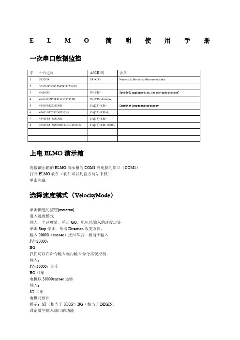
E L M O简明使用手册一次串口数据监控上电ELMO演示箱连接演示箱的ELMO演示箱的COM1到电脑的串口(COM1)打开ELMO软件(软件可以到官方网站下载)单击完成选择速度模式(VelocityMode)单击圈选的按钮(motoron)进入速度模式输入一个速度值,单击GO,电机以输入的速度运转单击Stop停止,单击Direction改变方向。
输入20000(cnt/sec)按回车后,相当于输入JV=20000;BG我们可以在命令输入框内输入命令实现控制。
输入:JV=30000;回车BG回车电机以30000cnt/sec运转输入:ST回车电机将停止提示:ST(相当于STOP)BG(相当于BEGIN)我们可以设定INPUT1为高电平,硬停止通过命令输入JV=30000;BG电机开始旋转,然后将INPUT1拨动到高电平,电机停止,当INPUT1拨回高电平后,电机恢复运转,因为硬停止,并不更改软件的运动状态。
但是,当我们使用“SoftStop”时,当我们置INPUT1为高电平后,软件也停止了,即使,再让INPUT1为高电平后,电机也不能恢复运转。
其他功能的配置如下:更多指令MO=1MO=0以上的含义是:Motoron/offUM Unitmode:stepper,torquecontrol,speedcontrolpositioncontrolordualloop CurrentMode电流模式下,输入命令UM返回1VelocityMode速度模式下,输入命令UM返回2StepperMode步进模式下,输入命令UM返回3DualLoopMode,输入命令UM返回4PositionMode,输入命令UM返回5Unitmode(UM):DefinesthefunctionoftheMetronome.Theunitmodesare: ∙UM=1Torquecontrol∙UM=2Speedcontrol∙UM=3Micro-stepping∙UM=4Dual-feedbackpositioncontrol∙UM=5Single-feedbackpositioncontrolRM Referencemode:external(analog)referencingenabled/disabled所有命令:Command DescriptionPP[N]DefinetheparametersoftheCANorRS-232communicationCommand DescriptionAG[N]AnaloggainsarrayAS[N]AnaloginputoffsetsarrayBP[N]BrakeparameterCA[N]CommutationparametersarrayCL[N]CurrentcontinuouslimitationsarrayEF[N]EncoderfilterfrequencyEM[N]ECAMparametersFF[N]FeedforwardFR[N]FollowerratioHM[N]HomingandcapturemodeHY[N]AuxiliaryhomeandcapturemodeMC Definemaximumpeakcurrentofservodrive,inamperesMP[N]Motion(PT/PVT)parametersPL[N]PeakdurationandlimitPM ProfilermodePT PositiontimecommandPV PositionvelocitytimecommandPW[N]PWMsignalparametersQP PositionQT TimeQV VelocityRM Referencemode:external(analog)referencingenabled/disabledTR TargetradiusUM Unitmode:stepper,torquecontrol,speedcontrolpositioncontrolordualloop VH[N]HighreferencelimitVL[N]LowreferencelimitXM[N]XModuloYM[N]YModuloCommand DescriptionGS[N]GainschedulingKG[N]GainscheduledcontrollerparametersKI[N]PIDintegraltermsarrayKP[N]PIDproportionaltermsarrayKV[N]AdvancedfilterforspeedloopXA[N]Extraparameters?(more)XP[N]ExtraparametersCommand DescriptionBH GetasamplesignalashexadecimalRC Variablestorecord(twovariablesateachrecordingsequence)RG Recordinggap,insamples.Gapbetweenconsecutivedatarecordings.RL RecordlengthRP[N]RecorderparametersRR Recordingon/offRV[N]RecordedvariablesYM[N]AuxiliarysensormodulocountCommand DescriptionAB[N]AbsoluteencodersettingparametersID ReadactivecurrentIQ ReadreactivecurrentPE PositionerrorPX Mainencoderposition,incountsPY AuxiliarypositionVE Velocityerror,incountspersecond2VX Mainencodervelocity,incountspersecond2VY VelocityofauxiliaryfeedbackYA[N]AuxiliarypositionsensorparametersCommand DescriptionCD CPUdump:CPUanddatabaseexceptionsummaryDF DownloadfirmwareDS DownloadfirmwareEO EchomodeHX SelecthexadecimalordecimalmodeLD LoadparametersformflashmemoryRS ResetMetronometoapre-definedstateandparametervalue SV SaveparameterstoflashmemoryTM SystemtimeTP[N]FloatingwizardparametersTS SamplingtimeTW[N]WizardcommandUF[N]UserfloatarrayUI[N]UserintegerWI[N]Metronomedata,mainlyforusebyComposerWS[N]Metronomedata,mainlyforusebyComposerZP[N]IntegerwizardparametersZX[N]Userprogramandauto-tuningtemporarystorage Command DescriptionAN[N]ReadanaloginputsIB[N]Bit-wisedigitalinputIF[N]DigitalinputfilterIP ReadalldigitalinputsOB[N]Bit-wisedigitaloutputOC[N]OutputCompareOL[N]OutputLogicOP SetalldigitaloutputsCommand DescriptionAC Acceleration,incountspersecond2BG BeginmotionBT BeginmotionatdefinedtimeDC Deceleration,incountspersecond2IL[N]Inputlogic,defininghowdedicatedinputsbehaveJV Speedofjoggingmotion,incountsperssecond2MO Motoron/offPA Absolutepositionreferenceforpoint-to-pointmotionPR Relativepositionreferenceforpoint-to-pointmotionSD StopdecelerationSF SmoothfactorformotioncommandSP Speedforpoint-to-pointmotionST StopmotionusingdecelerationvalueTC TorquecommandCommand DescriptionER[N]MaximumtrackingerrorsHL[N]Over-speedlimitandpositionrangelimitLL[N]LowactualfeedbacklimitPL[N]Peakcurrent,inamperes;andpeakduration,insecondsCommand DescriptionBV MaximummotorDCvoltageDD CANcontrollerstatusDV[N]ReferencedesiredvalueEC Errorcode:getcodeforlastinterpretererrorLC Currentlimitation:reportstatusofcurrentlimitationalgorithmMF Motorfault:codeforlastmotor-disablecauseMS MotionstatusreportingPK PeakmemorySN SerialnumberSR Numerical,bit-codedMetronomestatusTI[N]TemperatureindicationsarrayVR Software(firmware)versionCommand DescriptionCC CompileprogramCP ClearapplicationprogramDL ReceiveaprogramdownloadedfromhostcomputertoMetronome.CanbeusedonlyinComposersoftware.HP HaltprogramexecutionKL Killmotionandstopprogram(likeHP)LP[N]ListparametersLS ListprogramMI MaskinterruptPS ProgramstatusXC Continueprogramexecutionfromcurrentpointer,optionallyuntilagivenbreakpointXQ Executeprogram,optionallystartingatagivenlabelanduntilagivenbreakpoint ELMO编程基础增加模拟量输入:##STARTmo=0um=2il[1]=7il[2]=7il[3]=7il[4]=7il[5]=7mo=1while(1)if(ib[1]==1)jv=20000elseif(ib[2]==1)elseif(ib[3]==1)jv=50000elseif(ib[4]==1)jv=-50000elseif(ib[0]==1)jv=an[1]*60000endbgend下载程序流程:首先,让电机进入motoroff状态编译或者快捷键F7没有错误,编译成功时,单击,下图红色圆圈,上载程序到ELMO驱动器。
四川埃姆克伺服主轴选型手册v1.0

额定功率 (kW)
2.2 3.7 5.5 3.7 5.5 7.5 7.5 11 15
额定转矩 (Nm)
7 11.7 17.5 11.7 17.5 24 24 35 48
电机型号
DH09-1-14-2.2/3.7-1500 DH09-2-24-3.7/5.5-1500 DH10-1-24-3.7/5.5-1500 DH10-2-35-5.5/7.5-1500 DH10-3-48-7.5/11-1500 DH13-1-71-11/15-1500 DH13-2-95-15/18.5-1500 DH13-3-117-18.5/22-1500 DH13-4-140-22/30-1500 DH16-1-191-30/37-1500
265
15
110
5
DH13-4-140-22/30-1500
265
230
265
15
110
5
DH16-1-191-30/37-1500
320
300
350
19
140
5
D
Q
L
H
28
8
420
240
28
8
470
240
38
10
470
275
38
10
510
275
38
10
560
275
48
14
620
355
48
14
665
额定功率 (kW)
2.2 3.7 3.7 5.5 7.5 11 15 18 22 30
额定转矩 (Nm)
14 24 24 35 48 71 95 117 140 191
Summa ED3L 系列脉冲型交流伺服驱动器产品手册说明书
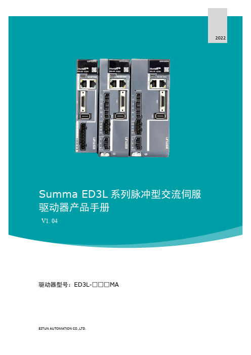
2022 Summa ED3L系列脉冲型交流伺服驱动器产品手册V1. 04驱动器型号:ED3L-□□□MAESTUN AUTOMATION CO.,LTD.前言概述本手册对Summa ED3L系列脉冲型交流伺服驱动器(以下简称“ED3L”)的选型、设计、试运行、调整、运行、维护所需的信息进行了说明。
请认真阅读本手册并妥善保管,以便需要时可以阅读和参考。
术语与缩写本手册可能使用的术语或缩写如下所述。
下表列出了本手册中用于EtherCAT和CANopen的缩写及其含义。
下表列出了本手册中使用的数据类型和范围。
符号约定在本文中可能出现如下安全标志,它们所代表的含义如下。
在本手册的正文中,反信号名(L电平时有效的信号)通过在信号名前加(/)来表示。
例如:S-ON= /S-ON P-CON= /P-CON关于参数的书写,调整型参数书写为Pn XXX(XXX是唯一的编号),而功能型参数包括了最多4个功能,书写为Pn XXX.X。
例如:●Pn112(速度前馈),是一个不含子参数(功能)的调整型参数。
●Pn000(基本功能设定0),是由四个不同的子功能组成的功能型参数。
−Pn000.0(Servo ON),表示为电机通电的方法。
−Pn000.1(禁止正转输入),表示外部P-OT信号的生效方式。
−Pn000.2(禁止反转输入),表示外部N-OT信号的生效方式。
−Pn000.3(保留),未定义其功能,请勿变更该参数的设定。
安全注意事项整体注意事项危险⏹请勿在驱动器通电的状态下,拆下外罩、电缆、连接器及选购设备。
⏹请勿在驱动器的输出端子U 、V 、W 上连接三相电源。
⏹ 请在断开电源至少5分钟,确认电源指示灯(CHARGE)已熄灭,再进行接线及检查作业。
即使断开了电源,驱动器内部仍然可能残留高电压。
因此,在电源指示灯(CHARGE)亮灯期间,请勿触摸电源端子。
警告 ⏹请使用与产品相符的电源规格(相数、电压、频率、AC/DC )。
信捷伺服手册

b
目录
目录
前言 ......................................................................................................................................................... I 本手册的内容构成........................................................................................................................... I 本手册的适用读者........................................................................................................................... I 手册的获取途径............................................................................................................................... I
2.请勿直接触摸产品的导电部位。 有可能引起误动作、故障。
z 产品的接线
危险
1.在对驱动器进行接线操作前,请务必断开所有外部电源。 有触电的危险。
2.请将 AC 电源正确连接到驱动器的专用电源端子上。 接错电源,可能引起火灾。
注意
1.请勿将驱动器的输出端子 U、V、W 与三相电源连接。 a
艾默生M700驱动器:选型手册

智能机器架构有何不同之处? • 标准网络硬件——没有限制的可集成性 • 轻松获得出色的性能——先进且易于使用的软件工具,经测试
可加快机器开发并能使机器发挥最佳性能 • 网络效率得到提高——非集中式网络智能消除了网络流量瓶颈 • 包容性网络——支持 PROFINET、EtherNet/IP 和 Modbus TCP/
支持以下 IEC 61131-3 编程语言:
• 结构化文本 (ST) • 功能块图 (FBD) • 结构化功能图 (SFC) • 梯形图 (LD) • 指令表 (IL) 还支持:
• 连续功能图 (CFC) 直观的智能感知功能有助于写入一致、可靠的程序,加速软件 开发。程序员可以使用充满活力的开放源代码社群获取功能 块。Control Techniques 还支持客户自己创建的功能块库,使用用 户定义的监视窗口在线监控程序变量,并支持在线程序更改。
Unidrive M 制造自动化驱动器系列
Unidrive M——专门针对客户需求定制的 制造自动化驱动器系列
Control Techniques依据以客户为导向的原则做了大量而广泛的市 场调研,并据此精心定制了 7 款 Unidrive M 的功能,以满足制造 自动化领域中特定的应用需求。Unidrive M700 具备板载实时以 太网,支持广泛的位置反馈和永磁伺服电机的高性能动态控制。 此外,对制造自动化领域的现有 Unidrive SP 用户而言,它可实现 全面兼容的升级。
Control Techniques 智能机器架构使用标准以太网将机器控制器部 之间的通讯,Unidrive M 使用 TCP/IP 和 UDP 等开放式协议,可提
件与其它设备(如 PC、I/O 和 HMI 等)连接在一起。以太网可为 供卓越的性能:
伊莱斯伺服 ESDA说明书1.01
安全注意事项ESDA系列通用型伺服驱动器,采用DSP+FPGA体系结构,加快了数据的采集和处理速度,集成度高、可靠性好。
丰富的数字量与模拟量接口,能与多种上位控制装置配套。
优化的PID控制算法,实现转矩、速度、位置精确的全数字控制,精度高、响应快,可使用于多种工业应用场合。
在产品存放、安装、配线、运行、检查和维修前,用户必须熟悉并遵守以下重要事项,以确保安全地使用本产品。
1、产品检查交流伺服驱动器必须与性能匹配的伺服电机配套使用。
2、安装禁止将产品暴露在有水气,腐蚀性、可燃性气体的场合使用,否则会导致触电或火灾。
3、配线电源,否则会造成设备损坏、触电或火灾。
4、操作注意通电前应确认伺服驱动器和伺服电机已安装稳妥,固定牢固,电源电压及接线正确。
运行时,禁止触摸任何旋转中的电机零件,否则可能会造成人员受伤。
5、故障处理除指定的专业人员外,请勿进行连接、安装、操作、拆卸与维修工作,有触电和损坏设目 录第一章 产品说明 (1)1.1铭牌型号说明 (1)1.2驱动器各部分名称 (2)1.3伺服驱动器技术规范 (3)第二章 安装 (4)第三章 配线 (7)3.1外围设备的连接 (7)3.2电源接线实例 (8)3.3伺服驱动器接线 (9)3.3.1 伺服驱动器标准接线图 (9)3.3.2 绝对值编码器接线 (10)3.3.3旋转变压器接线 (10)第四章 接口 (11)4.1主回路端子定义 (11)4.2CN1编码器反馈端子定义 (11)4.3CN2控制端子定义 (12)4.4CN3通信接口端子定义 (13)4.5数字输入输出接口原理 (14)4.5.1 数字输入接口原理 (14)4.5.2 数字输出接口原理 (14)4.6位置脉冲指令输入接口原理 (15)4.7模拟量输入输出接口原理 (18)4.7.1 模拟指令输入接口原理 (18)4.7.2 模拟量输出接口原理 (19)4.8编码器信号输入输出接口原理 (19)4.8.1 编码器信号输出CN2接口原理 (19)4.8.2 编码器信号输入CN1接口原理 (20)第五章 面板操作 (21)5.1面板操作概述 (21)5.2菜单结构 (21)5.2.1状态参数查看操作 (22)5.2.2参数编辑操作 (23)5.2.3特殊功能参数 (24)第六章 通信功能 (25)6.1MODBUS通信概要 (25)6.2MODBUS通信协议 (25)第七章 参数与功能 (31)7.1参数一览表 (31)7.2参数设置详解 (39)7.3数字输入DI功能定义 (54)7.4数字输出DO功能定义 (56)第八章 报警与处理 (58)第九章 运行与调试 (61)9.1驱动器通电 (61)9.2空载运行调试 (61)9.3控制功能调试 (62)9.3.1 位置控制 (62)9.3.2 速度控制 (64)9.3.3 转矩控制 (65)第十章 伺服电机说明 (67)10.1铭牌型号说明 (67)10.2电机各部分名称 (68)10.3伺服电机的安装 (68)10.4伺服电机端子定义及连线 (72)附录A (74)⏹电机适配表 (74)⏹电缆型号 (75)⏹电机信号线(编码器线)电缆型号说明 (76)⏹电机动力线电缆型号说明 (76)第一章 产品说明 1.1铭牌型号说明1、铭牌说明图1.1 伺服驱动器铭牌说明2、型号说明图1.2 伺服驱动器型号说明1.2驱动器各部分名称:不可与主回路电源连接,连接错误时易造成驱动器损坏。
ELMO首次调试方法
Elmo驱动器的调试方法1.正确接线并保证通讯正常,而后将进入如下画面2.选择正确 的波特率并 点击下面连 接按钮1.选择RS232 串口通讯方 式,并点击右 下方按钮选择驱动器运行模式 1.电流环 2.速度环 度环 3.步进模式 4.全闭环 5.位置环按此按钮 将打出下面 motion Moni motion_Moni tor监视面板在此选择需 要监视的项 目,可以是电 压,电流,速度, 位置等点击左边两个绿 色选项,选择监视 的分辨率,图中为 监视1.84秒选择反馈方式 1.电流 2 辅助位置 2. 3.当前位置 4.位置错误 5 速度(RPM) 5.选择系统加速度 与减速度点击选择监视方 式,选择Begin motion ti 为电机运 转后马上启动,1.点击右边Jogging 1 J i mode d 进 入调试状态, 2.在速度处输入希望的速 度,点击右边GO即可运行 3.如果不选择jogging mode 模式,则需要在下面输入速 度和位置,电机则从当前位 置运行至希望位置观察IO状态, 左侧输入, 右侧输出当需要记录时, 需要率先点击 Start Record系统滤波界面Noise Filter 当系统出现较大的杂波干扰时,需要加入系统的滤波装置 例如:当系统使用外界脉冲跟随时,发现系统跟随不正常,外界输 入了大量不正确的杂波,此时需要加入辅助编码器的滤波装置选择系统滤波 编码器滤波与数 字IO的滤波主编码器滤波辅助编码器滤波系统保护界面(Protections) (P t ti ) 该界面定义驱动器的 些保护参数包括电流,电压,刹车, 该界面定义驱动器的一些保护参数包括电流 与跟随误差等 例如:可以在该界面输入输入电压的高低限制,刹车的开 启松开时间,速度与位置的跟随误差等系统各种限制参数(Limits) (Li it ) 在此输入电流,电压位置等的各种限制 例如:1.系统额定电流,峰值电流与峰值电流持续时间 2.速度的上下限与减速度 3.位置的上下限 4.反馈的上下限系统的增益(Digital Filter)包括电流环,速度环与位置环用户自设定参数(Customer)供用户编写简单的小命令,如果需要编写程序则需要Elmo studio模拟量输入控制(Analog Input)在该界面进行模拟量控制例如:1. 在速度环下通过外界±10V电压信号来控制驱动器的速度2.在电流环下通过外界±10V电压信号来控制驱动器的电流具体设定请查阅配套例程首先设置系统零漂设定1V电压对应驱动器的电流输出IO输入孔定义(Input Logic)设定IO输入接头的定义,具体使用程序请查阅配套例程IO输出孔定义(Output Logic)设定IO输出接头的定义,具体使用程序请查阅配套例程进行简单电机试运转的相关步骤11.正确连接驱动器,电机,电脑,按照图1选择正确的拨特率(通讯不上可以反复多选几个选项2.如图2打开下面监视面板,选择需要监视的参数3.选择需要监视的时间与分辨率4.选择监视的种类Begin motion:电机运转后才开始监视No trigger:点击后马上开始监视动行点到点行,在试行模式行,5.Elmo驱动器可以进行点到点的运行也可以在试运行模式下一直运行6.当需要监视电机状态时,需要按1~4设定监视方式,而后如图6点击Recorder,最后点击GO 运行驱动器,当监视时间达到后,驱动器会生成一个新的软件,在该软件上即可检查电机相关运行情况.如果步了解。
A1E 系列交流伺服驱动器 用户手册说明书

基本规格 ........................................................................................................................................... 4
速度、位置、转矩控制规格 ........................................................................................................... 5
1
1.1
1.2
1.3
1.4
1.5
2
2.1
2.2
2.2.1
2.2.2
2.3
2.4
2.5
3
3.1
3.2
3.3
4
4.1
4.2
4.3
4.4
4.5
4.5.1
4.5.2
4.5.3
5
安全提醒 ................................................................................................................................................... 1
信捷伺服手册
注意
错误使用时,可能会产生危险,有可能受到中度的伤害或受轻伤的情况下,以 及有可能造成财产损失的情况下。
危险
错误使用时,可能会产生危险,引发人身伤亡或者受到严重伤害,以及有可能 造成严重的财产损失的情况下。
z 拿到产品时的确认
注意
1.受损的驱动器、缺少零部件的驱动器,或者是型号不符合要求的驱动器,请勿安装。 有受伤的危险。
用户须知只有具备一定的电气知识的操作人员才可以对产品进行接线等其他操作如有使用不明的地方请咨询本公司的技术部门
DS2 系列伺服驱动器
用户手册
信捷科技电子有限公司
资料编号 SC2 01 20100812 1.0
信捷电子
DS2 系列伺服驱动器 用户手册
安全注意事项
目录
前言
————————————————
1 产品的确认及各部分名称.................................................................................................................. 1 1-1.产品到货时的确认................................................................................................................. 1 1-1-1. 伺服电机 ....................................................................................................................... 1 1-1-2.伺服驱动器 .................................................................................................................. 2 1-2.产品各部分名称..................................................................................................................... 2 1-2-1.伺服电机 ...................................................................................................................... 2 1-2-2.伺服驱动器 .................................................................................................................. 2
欧诺克 直流伺服电机 驱动器 产品说明书

深圳市欧诺克科技有限公司Shenzhen ONKE Technology Co., Ltd.座机:*************27381841电话:邓先生135****7106陈先生139****0920邮箱:***************网 址 : 地址:广东省深圳市宝安区福海街道怀德翠湖工业园13栋稳定的质量是我们赖以生存的根本优质的服务是我们继续发展的前提客户的满意是我们唯一追求的目标产品画册Product gallery专业生产伺服驱动器、伺服电机及自动化控制系统深圳市欧诺克科技有限公司直流伺服驱动器电机09目录匠心制造精益求精“一、公司介绍01(一) 直流伺服驱动器021.驱动器介绍与型号说明032.DC系列技术指标033.DE系列技术指标044.DE2系列技术指标055.驱动器应用领域066.驱动器外设配件07(二) 直流伺服电机081.电机介绍与型号说明2.电机应用领域3.电机规格参数表4.电机规格尺寸图101112C O M P A N Y PROFILE以精密制造引领未来Leading the future with precision manufacturing公司简介Company Profile深圳市欧诺克科技有限公司成立于2010年,是一家专业研发生产伺服电机和驱动器的高新技术企业,公司技术力量雄厚,检测手段先进,欧诺克人本着不求最全,只求最精的信念,为生产出各类伺服电机、各类驱动器而不懈奋斗。
欧诺克人以鹰的精神,挑战尖端,研发生产出高性价比的各类伺服电机和驱动器,以鹰的敏锐洞察力洞察市场,与时俱进、创新来满足市场的需求。
深圳市欧诺克科技有限公司产品主要有:伺服驱动器、伺服电机、直流伺服驱动器,直流伺服电机,交流伺服驱动器,交流伺服电机,低压伺服驱动器,低压伺服电机,直线电机驱动器,DDR马达驱动器,音圈电机驱动器,直流无刷驱动器,直流无刷电机,CANopen总线、EtherCAT总线、电子凸轮伺服系统,大功率伺服驱动器、大电流伺服驱动器,专用运动控制伺服驱动器和自动化控制系统,十多年来凭借精湛的技术与国内国外众多知名企业公司建立了互利共赢的合作。
elmo 驱动器硬件连接说明

Solo WhistleDigital Servo Drive Cable KitCBL-MLXAICBL-MLXAUXCBL-MLXFDBKCBL-SOLKIT-001December 2008 (Ver. 1.0)Important NoticeThis guide is delivered subject to the following conditions and restrictions:This guide contains proprietary information belonging to Elmo Motion ControlLtd. Su for the purpose of assisting users of the Solo Whis e. The te and ref change ElmoMotion InfoMAN-CBLKIT-SOLWHI (Ver 1.0)Copyright © 2008E .Revision History: ch information is supplied solely tle servo drive in assembling the required cables for their driv xt and graphics included in this manual are for the purpose of illustrationerence only. The specifications on which they are based are subject to without notice. Motion Control and the Elmo Motion Control logo are trademarks of Elmo Control Ltd. rmation in this document is subject to change without notice. lmo Motion Control Ltd.All rights reserved VersionRe Date lease StatusChanges/RemarksVer. 1.0 December 2008 Initial ReleaseElmo Motion Contr 64 Gissin St., P.O. Bo Petach Tikva 49103 IsraelTel: +972 (3) 929-2300 Fax: +972 (3) 929-2322 info-il@ol Ltd. x 463 otion C ive, S d, MA USATel: +1 (978) 399-0034 Fax: +1 (978) 399-0035 info-us@Elmo M ontrol Inc. 1 Park Dr uite 12 Westfor 01886 o Mot kirch 056, V gen GermanyTel: +49 (0) 7720-85 77 60 Fax: +49 (0) 7720-85 77 70 info-de@Elm ion Control GmbH Stein ring 1D-78illingen-SchwenninSolo Whistle Cable Kit iMAN-CBLKIT-SOLWHI (Ver 1.0)Contents1. Introduction...................................................................................................................1-1 1.1 Solo Whi ............................................................................................................1-1 1.2 Cable Cro ............................................................................................................1-21.2.1Solo W -22. Cable Kit..........-13. Main Feedback Cable (CBL-MLXFDBK)....................................................................3-14. Auxiliary Fee -15. Communicati -1 5.1 RS232 Communication Cable (CBL-MLXAI) 5.2 CAN In &6. I/O Cable (CBL-MLXFDBK)........................................................................................6-1stle Connectors............ss Reference................histle...................................................................................................................1...............................................................................................................2dback Cable (CBL-MLXAUX)...............................................................4on Cables................................................................................................5..................................................................................5-1 O 5-1ut Communication Cables (CBL-MLXAI)................................................................Solo Whistle Cable KitMAN-CBLKIT-SOLWHI (Ver 1.0)1-11. IntroductionThis document provides the wiring details for the cables used to connect the Elmo Solo-Wh end-user application. The servo drive-side pinouts drive’s installation guide. The cables com 1.1 Solo The table belo histle drive and specifies the cableistle digital servo drive with the are provided in Chapter 3 of the e in one length: 2 meters (6 ½ feet).Whistle Connectorsw presents the connector panel of the Solo W connectors. Table 1-1: Connectors on the Solo Whistle DriveSolo Whistle Cable Kit IntroductionMAN-CBLKIT-SOLWHI (Ver 1.0)1-21.2 Cable Cross Reference1.2.1 S eCable Appl PinsPin Location olo Whistl ication Cable Part. No.PageMain Feed -MLXFDBK 12 J4 3-1back CBL Auxiliary Feedb CBL-ML 8 1ack XAUX J3 4-RS232 Communica CBL-ML 3 J5 5-1tion XAI CANIN CBL-MLXAI 3 J6 5-1CANOUT CBL-ML 3 J7 5-1XAI I/OCBL-ML 12 J2 6-1XFDBKT 2: Cable and Pin Cross-Refer Whist riveable 1-ence for the Solo le DSolo Whistle Cable KitMAN-CBLKIT-SOLWHI (Ver 1.0)2-12. Cable KitThe Solo W (CBL-SOLKIT-001) is available for purchase directlyfrom Elmo Motion Control. The cable kit includes the six cables listed in Table2-1. All the Cable Appli histle Cable Kit cables are 2 m long. cation CBL-SOLKIT-001ck Main Feedba CBL-MLXFDBK Auxiliary Feedb CBL-M ack LXAUX RS232 Commu CBL-M nication LXAI CANIN CBL-MLXAI CANOUT CBL-MLXAI I/OCBL-MLXFDBKTable 2-1: Cable Kit for the Solo Whistle Drive3. Main Feedback Cable (CBL-MLXFDBK)The main feedback cable is made from 24-AWG, six twisted-pair shielded cable. There is one type of feedback cable, which uses a 12-pin Molex 2 mm pitch plug on the SimplIQ side.The Main Feedba connected to cusck Cable (CBL-MLXFDBK) is open on the motor side so that it can be tomer-specific connectors. The specific fun h pin is fully outlined in the Solo Whistle Installation Guide .ctionality of eacFigure 1: Single-sided Main Feedback Cable (Part No. CBL-MLXFDBK)4. Auxiliary Feedback Cable (CBL-MLXAUX)The auxiliary feedback cable is a 24-AWG twisted-pair shielded cable. It is connected using an 8-pin Molex 2 mm pitch plug.Four op Installation Guide Main encode Differential e Sing Puls The Auxi X) is open on the motor side so that it can be connectetions — described in theAuxiliary Feedback section(s) in the Solo Whistle — are available for auxiliary feedback: r buffered outputs ncoder inputs le-ended encoder input e-and-direction inputliary Feedback cable (CBL-MLXAU d to customer-specific connectors.The specific fun in is fully outlined in the Solo Whistle Installation Guides .ctionality of each pFigure 2: Auxiliary Feedback Cable (Part No. CBL-MLXAUX)5. Communication CablesThe communication cables use 26-AWG two twisted pair shielded cable. They are connected using a 3-pin Molex 2 mm pitch plug. Elmo drives can communicate using the follow RS-232, full d CAN open (C The Com XAI) are open on the motor side so that it can be connecte 5.1 RS232ing options: uplexAN in & CAN out)munication Cables (CBL-ML d to customer-specific connectors.Communication Cable (CBL-MLXAI)Figure 3: RS2325.2 CAN In & Out Communication Cables (CBL-MLXAI)Communication Cable (Part No. CBL-MLXAI)Figure 4: CAN In and Out Communication Cable (Part No. CBL-MLXAI)6. I/O Cable (CBL-MLXFDBK)The I/O cable is made from 24-AWG, six twisted-pair shielded cable. There is one type of I/O cable, which uses a 12-pin Molex 2.0 mm pitch plug on the SimplIQ side.The I/O Cab e connected to customer-specifile (CBL-MLXFDBK) is open on the motor side so that it can b c connectors. The specific fun h pin is fully outlined in the Solo Whistle Installation Guide .ctionality of eacFigure 5: I/O Cable (Part No. CBL-MLXFDBK)。
i3系列全数字交流伺服驱动器EtherCAT使用手册V0.11

i3系列全数字交流伺服驱动器——EtherCAT使用手册南京图科自动化设备有限公司THINKVO Automation Equipment Co.,Ltd——目录——1、前言 (4)1.1入门指导 (4)2、系统概述 (6)2.1 EtherCAT概述 (6)2.3 系统组成(主站*从站组成) (6)2.4 规格一览 (7)3、EtherCAT通信规格 (8)3.1 EtherCAT帧结构 (8)3.2 ESM(EtherCAT State Machine)状态机 (10)3.3 ESC地址空间 (11)3.4 SII(Slave Information Interface)EEPROM (12)3.5 通信同步模式 (14)3.5.1 DC同步 (14)3.5.2 SM同步 (15)3.5.3 FreeRUN非同步 (15)3.6 SDO (16)3.6.1 异常发生时的信息 (17)3.7 PDO (19)3.7.1 PDO映射对象 (19)3.7.2 PDO分配对象 (20)3.8 前面板构成及Node Address设置 (21)3.8.1 基本模式的选择与操作 (21)3.8.2 状态显示模式及EtherCAT Indicators (22)3.8.3 Node addressing(Station alias设定) (24)4、对象通用规格 (26)4.1 对象结构 (26)5、CoE通信区域(1000h-1FFFh) (27)5.1 对象一览 (27)5.2 设备信息 (29)5.3 SM communication type(1C00h) (30)5.4 PDO映射 (31)5.4.1 PDO分配对象 (31)5.4.2 PDO映射对象 (32)5.4.3 默认PDO映射 (34)5.4.4 PDO映射设定步骤 (36)5.5 SM2/3 synchronization(1C32、1C33h) (37)5.5.1 DC(SYNC0 Event同步) (40)5.5.2 SM2(SM2 Event同步) (42)5.5.3 FreeRun(非同步) (43)5.5.4 Input shift time (45)5.6 Diagnosis history(报警履历读取功能 10F3h) (46)6、驱动Profile区域(6000h-6FFFh) (48)6.1 对象一览 (48)6.2 PDS规格(控制状态机) (49)6.2.1 设备控制状态机 (49)6.3 controlword(6040h) (50)6.4 statusword(6041h) (51)6.5 控制模式设定 (52)6.5.1 supported drive modes(6502h) (52)6.5.2 modes of operation(6060h) (52)6.5.3 modes of operation display(6061h) (52)6.6 位置控制功能(csp/ip/pp/hm) (53)6.6.1 位置控制通用功能 (53)6.6.2 位置控制模式(PP) (54)6.6.3 Cyclic位置控制模式(CSP) (58)6.6.4 插补位置控制模式(IP) (59)6.6.5 原点复归控制模式(HM) (59)6.7 速度控制功能(csv/pv) (66)6.7.1 速度控制通用功能 (66)6.7.2 Profile速度控制模式(pv) (67)6.7.3 Cycle速度控制模式(csv) (69)6.8 转矩控制功能(pt/cst) (71)6.8.1 转矩控制通用功能 (71)6.8.2 Profile转矩控制模式(tq) (72)6.8.3 cycle转矩控制模式(csq) (73)6.9 模式通用功能 (74)6.9.1 touch probe功能 (74)6.9.2 Digital inputs/Digital outputs (78)8、对象字典一览表 (79)1、前言1.1入门指导在PP控制(Profile Position Mode)下,对电机独立动作的操作进行描述。
电动伺服器 滑动类型系列LEKFS E产品说明书

Instruction ManualElectric Actuator / Slider type Series LEKFS**EMotor: Step motor (servo 24 VDC) with Battery-less absolute encoderThe intended use of this Electrical Actuator is to convert an electrical input signal into mechanical motion.1 Safety InstructionsThese safety instructions are intended to prevent hazardous situations and/or equipment damage. These instructions indicate the level of potential hazard with the labels of “Caution,” “Warning” or “Danger.” They are all important notes for safety and must be followed in addition to International Standards (ISO/IEC) *1), and other safety regulations. *1)ISO 4414: Pneumatic fluid power - General rules relating to systems. ISO 4413: Hydraulic fluid power - General rules relating to systems.IEC 60204-1: Safety of machinery - Electrical equipment of machines. (Part 1: General requirements)ISO 10218-1: Manipulating industrial robots -Safety. etc.∙ Refer to the product catalogue, Operation Manual and Handling Precautions for SMC Products for additional information. ∙ Keep this manual in a safe place for future reference.CautionCaution indicates a hazard with a low level of risk which, ifnot avoided, could result in minor or moderate injury.WarningWarning indicates a hazard with a medium level of riskwhich, if not avoided, could result in death or serious injury.DangerDanger indicates a hazard with a high level of risk which, ifnot avoided, will result in death or serious injury.Warning∙ Always ensure compliance with relevant safety laws and standards. All work must be carried out in a safe manner by a qualified person in compliance with applicable national regulations.2 SpecificationsLEKFS25 seriesModelLEKFS25 A c t u a t o r s p e c i f i c a t i o nStroke [mm] 100 to 500Max. work load [kg]Horizontal 12 25 30 Vertical0.57.515 Speed [mm/s] Note 1)In-Line to 500 stroke 20 to 1100 12 to 750 6 to 400 Parallel to 500 stroke20 to 90012 to 600 6 to 300Max. acceleration / deceleration [mm/s 2]3,000Positioning repeatability [mm] ±0.01 (lead H: ±0.02)Lost motion [mm] Note 2) 0.05 or less Screw Lead [mm]2012 6Impact/Vibration resistance [m/s 2] Note 3) 50 / 20 Actuation method Ball screw Guide typeLinear guide Operating temperature [℃] 5 to 40Operating humidity [%RH] 90 or less (no condensation)E l e c t r i c a lMotor size [mm] □42Motor typeBattery-less absolute (Step motor 24 VDC) Encoder(angular displacement sensor) Battery-less absolute (4096 pulses / rotation)Rated Voltage [V]24 VDC ±10%Power consumption [W] Note 4) 38Standby power consumption [W] Note 5)16 Max. instantaneous power consumption [W] Note 6) 57L o c kLock Type Note 7)Non magnetizing lock Holding force [N] 4778 157Power consumption [W] Note 8)5 Rated voltage [V]24 VDC ±10%LEKFS32 seriesModelLEKFS32 A c t u a t o r s p e c i f i c a t i o nStroke [mm] 100 to 500Max. work load [kg]Horizontal 20 45 50 Vertical41020 Speed [mm/s] Note 1)In-Line to 500 stroke 24 to 1200 16 to 800 8 to 400 Parallel to 500 stroke24 to 800 16 to 6508 to 325Max. acceleration / deceleration [mm/s 2]3,000Positioning repeatability [mm] ±0.01 (lead H: ±0.02)Lost motion [mm] Note 2)0.05 or lessScrew Lead [mm]2416 8Impact/Vibration resistance [m/s 2] Note 3) 50 / 20 Actuation method Ball screw Guide typeLinear guide Operating temperature [℃] 5 to 40Operating humidity [%RH] 90 or less (no condensation)E l e c t r i c a lMotor size [mm] □56.4Motor typeBattery-less absolute (Step motor 24 VDC) Encoder(angular displacement sensor) Battery-less absolute (4096 pulses / rotation)Rated Voltage [V]24 VDC ±10%Power consumption [W] Note 4) 50Standby power consumption [W] Note 5)44 Max. instantaneous power consumption [W] Note 6) 123L o c kLock Type Note 7)Non magnetizing lock Holding force [N] 72108 216Power consumption [W] Note 8)5 Rated voltage [V]24 VDC ±10%2 Specifications (continued)L o c kLock Type Note 7)Non magnetizing lock Holding force [N] 75113 225 Power consumption [W] Note 8)5 Rated voltage [V]24 VDC ±10%Note 1) Speed varies according to the work load. Check the “Speed–Work LoadGraph" as a Guide in the catalogue on the SMC website (URL: https:// ).Furthermore, if the cable length exceeds 5 m, then the speed and work load may decrease by up to 10% for each additional 5 m.Note 2) A reference value for correcting an error in reciprocal operation.Note 3) Impact resistance: No malfunction occurred when the actuator was testedwith a drop tester in both an axial and a perpendicular direction to the lead screw. The test was performed with the actuator in the initialized state. Vibration resistance: No malfunction occurred in a test ranging between 45 to 2000 Hz. The test was performed in both an axial and a perpendicular direction to the lead screw. The test was performed with the actuator in the initialized state.Note 4) The power consumption including the controller is for when the actuator isoperating.Note 5) Standby power consumption when operating (including the controller) iswhen the actuator is stopped in the set position during a positioning operation.Note 6) Maximum instantaneous power consumption (including the controller) iswhen the actuator is operating. This value can be used for the power supply selection.Note 7) For models with lock only.Note 8) For an actuator with lock, add the power consumption for the lock.2.1 Product weightSeriesLEKFS25 Stroke [mm]100 200 300 400 500 Product weight [kg] 1.82.12.4 2.62.9Lock weight [kg]0.3SeriesLEKFS32Stroke [mm]100 200 300 400 500 Product weight [kg] 3.33.74.2 4.65.0Lock weight [kg] 0.52 Specifications (continued)SeriesLEKFS40 Stroke [mm]200 300 400 500 600 Product weight [kg] 5.76.36.97.58.1Lock weight [kg]0.5WarningSpecial products (-X#, -D#) might have specifications different from those shown in this section. Contact SMC for specific drawings.3 Installation3.1 InstallationWarning∙ Do not install the product unless the safety instructions have been read and understood.∙ Do not use the product in excess of its allowable specification.∙ When installing, inspecting or performing maintenance on the product, be sure to turn off the power supplies. Then, lock it so it cannot be tampered with while work is happening.∙ Keep the flatness of the mounting surface to within 0.1 mm maximum. Insufficient flatness of a work piece or actuator mounting surface can cause play in the guide and increased sliding resistance. In the case of overhang mounting (including cantilever), use a support plate or support guide to avoid deflection of the actuator body.∙ When mounting the actuator, use all mounting holes.If all mounting holes are not used, this will not maintain the specified performance. e.g. the amount of displacement of the table will increase. ∙ When mounting the actuator leave a gap of 40 mm or more to allow for bending of the actuator cable.∙ When mounting the actuator or workpiece, use screws with adequate length and tighten them with adequate torque.Tightening the screws with a torque higher than recommended may cause malfunction, whilst tightening with a torque lower than recommended can cause displacement of the mounting position, or dropping of the work piece.Model Screw sizeMax. tightening torque [N.m]∅ A [mm]L [mm] LEKFS25 M4 1.5 4.5 24 LEKFS32 M5 3.0 5.5 30 LEKFS40M65.26.631ORIGINAL INSTRUCTIONSLEKFS40 seriesModelLEKFS40 A c t u a t o r s p e c i f i c a t i o nStroke [mm] 200 to 600Max. work load [kg] Horizontal 25 55 65 Vertical 2223Speed [mm/s]Note 1) In-Line to 500 stroke30 to 1200 20 to 850 10 to 300 501 to 600 stroke30 to 1200 20 to 850 10 to 300 Parallel to 500 stroke30 to 750 20 to 550 10 to 300 501 to 600 stroke 30 to 750 20 to 550 10 to 300Max. acceleration / deceleration [mm/s 2] 3,000Positioning repeatability [mm] ±0.01 (lead H: ±0.02)Lost motion [mm] Note 2) 0.05 or lessScrew Lead [mm] 3020 10Impact/Vibration resistance [m/s 2] Note 3) 50 / 20 Actuation method Ball screw Guide type Linear guide Operating temperature [℃] 5 to 40Operating humidity [%RH] 90 or less (no condensation)E l e c t r i c a lMotor size [mm] □56.4Motor type Battery-less absolute (Step motor 24 VDC) Encoder (angular displacement sensor) Battery-less absolute (4096 pulses / rotation)Rated Voltage [V] 24 VDC ±10%Power consumption [W] Note 4) 100 Standby power consumption [W] Note 5) 43 Max. instantaneous power consumption [W] Note 6) 141L o c kLock Type Note 7)Non magnetizing lock Holding force [N] 75113 225Power consumption [W] Note 8)5Rated voltage [V] 24 VDC ±10% Actuator Mounting3 Installation (continued)Work piece Mounting∙In order to prevent the work piece fixing screws from damaging the table, use screws at least 0.5 mm shorter than the maximum thread depth. Longer screws can hit the body and cause operation failure.Model Screw size Max. tighteningtorque [N.m]L Max. threaddepth [mm]LEKFS25M5 x 0.8 3.0 8LEKFS32 M6 x 1.0 5.2 9LEKFS40M8 x 1.25 12.5 133.2 EnvironmentWarning∙Do not use in an environment where corrosive gases, chemicals, salt water or steam are present.∙Do not use in an explosive atmosphere.∙Do not expose to direct sunlight. Use a suitable protective cover.∙Do not install in a location subject to vibration or impact in excess of the product’s specificatio ns.∙Do not mount in a location exposed to radiant heat that would result in temperatures in excess of the product’s specifications.∙Prevent foreign particles from entering the product.3.3 MountingWarning∙Observe the required tightening torque for screws.Unless stated otherwise, tighten the screws to the recommended torque for mounting the product.∙Do not make any alterations to the product.Alterations made to this product may lead to a loss of durability and damage to the product, which can lead to injury and damage to other equipment and machinery.Do not scratch or dent the sliding parts of the table or mounting face etc., by striking or holding them with other objects. The components are manufactured to precise tolerances, so that even a slight deformation may cause faulty operation or seizure.∙Do not use the product until it has been verified that the equipment can be operated correctly.After mounting or repair, connect the power supply to the product and perform appropriate functional inspections to check it is mounted correctly.∙Do not use the product until it has been verified that the equipment can be operated correctly.After mounting or repair, connect the power supply to the product and perform appropriate functional inspections to check it is mounted correctly.3.4 LubricationCaution∙SMC products have been lubricated for life at manufacture, and do not require lubrication in service.∙If a lubricant is used in the system, refer to the catalogue for details. ∙The recommended grease is lithium grade No.2Apply for Grease Pack order No.Ball screw and Guide GR-S-010(10g)GR-S-020(20g)4 Wiring4.1 WiringWarning∙Adjustment, mounting or wiring changes should not be carried outbefore disconnecting the power supply to the product.Electric shock, malfunction and damage can result.∙Do not disassemble the cables.∙Use only specified cables.Use only specified cables otherwise there may be risk of fire anddamage.∙Do not connect or disconnect the wires, cables and connectors whenthe power is turned on.Caution∙Wire the connector correctly and securely.Check the connector for polarity and do not apply any voltage to theterminals other than those specified in the Operation Manual.∙Take appropriate measures against noise.Noise in a signal line may cause malfunction. As a countermeasureseparate the high voltage and low voltage cables, and shorten thewiring lengths, etc.∙Do not route input/output wires and cables together with power or highvoltage cables.The product can malfunction due to noise interference and surgevoltage from power and high voltage cables close to the signal line.Route the wires of the product separately from power or high voltagecables.∙Take care that actuator movement does not catch cables.∙Operate with all wires and cables secured.∙Avoid bending cables at sharp angles where they enter the product.Avoid twisting, folding, rotating or applying an external force to thecable. Risk of electric shock, wire breakage, contact failure and loss ofcontrol of the product can result.∙Select “Robotic cables”in applications where cables are movingrepeatedly (encoder/ motor/ lock).∙Confirm correct insulation.Poor insulation of wires, cables, connectors, terminals etc. can causeinterference with other circuits. Also there is the possibility thatexcessive voltage or current may be applied to the product causingdamage.∙R efer to the auto switch references in “Best Pneumatics“ when an autoswitch is to be used4.2 Wiring of Actuator to Controller4.3 Actuator Ground connection∙The Actuator must be connected to ground to shield the actuator fromelectrical noise. The screw and cable with crimping terminal andtoothed washer should be prepared separately by the user.∙The ground wire cross sectional area should be 2 mm2 minimum.∙Avoid shared grounding points with other devices.5 How to OrderRefer to the catalogue on the SMC website(URL: https://) for the How to Order information.6 Outline Dimensions (mm)Refer to the drawings / operation manual on the SMC website(URL: https://) for outline dimensions.7 Maintenance7.1 General MaintenanceCaution∙Not following proper maintenance procedures could cause the productto malfunction and lead to equipment damage.∙If handled improperly electricity and compressed air can be dangerous.∙Maintenance of electromechanical and pneumatic systems should beperformed only by qualified personnel.∙Before performing maintenance, turn off the power supply and be sureto cut off the supply pressure. Confirm that the power has beendischarged and the air is released to atmosphere.∙After installation and maintenance, apply operating pressure andpower to the equipment and perform appropriate functional andleakage tests to make sure the equipment is installed correctly.∙If any electrical or pneumatic connections are disturbed duringmaintenance, ensure they are reconnected correctly and safety checksare carried out as required to ensure continued compliance withapplicable national regulations.∙Do not make any modification to the product.∙Do not disassemble the product, unless required by installation ormaintenance instructions.∙Incorrect handling can cause an injury, damage or malfunction of theequipment and machinery, so ensure that the procedure for the task isfollowed.∙Always allow sufficient space around the product to complete anymaintenance and inspection.7.2 Periodical Maintenance∙Maintenance should be performed according to the table below:FrequencyAppearanceCheckInternalcheckBeltCheckBefore daily operation ✓Every 6 months* ✓✓✓Every 1,000 km* ✓✓✓Every 5 million cycles* ✓✓✓*whichever of these occurs first.∙Following any maintenance, always perform a system check. Do notuse the product if any error occurs, as safety cannot be assured ifcaused by any un-intentional malfunction.7.3 Appearance Check∙The following items should be visually monitored to ensure that theactuator remains in good condition and there are no concerns flagged;・Loose Screws,・Abnormal level of dust or dirt,・Visual flaws / faults,・Cable connections,・Abnormal noises or vibrations.7.4 Belt Check∙If one of the 6 conditions below are seen, do not continue operatingthe actuator, contact SMC immediately.・Tooth shaped canvas is worn out.Canvas fibre becomes “fuzzy”, rubber is removed, and the fibre gainsa white colour. The lines of fibre become very unclear.・Peeling off or wearing of the side of the belt.The corner of the belt becomes round and frayed, with threadsbeginning to stick out.・Belt is partially cut.Belt is partially cut. Foreign matter could be caught in the teeth andcause flaws.・Vertical line of belt teeth.Flaw which is made when the belt runs on the flange.・Rubber back of the belt is softened and sticky.・Crack on the back of the belt.8 Limitations of Use8.1 Limited warranty and Disclaimer/Compliance Requirements∙Refer to Handling Precautions for SMC Products.9 Product disposalThis product should not be disposed of as municipal waste. Check yourlocal regulations and guidelines to dispose of this product correctly, inorder to reduce the impact on human health and the environment.10 ContactsRefer to or www.smc.eu for your local distributor /importer.URL : http// (Global) http// www.smc.eu (Europe)SMC Corporation, 4-14-1, Sotokanda, Chiyoda-ku, Tokyo 101-0021, JapanSpecifications are subject to change without prior notice from the manufacturer.© 2021 SMC Corporation All Rights Reserved.Template DKP50047-F-085MElectric Actuator / Slider typeJXC#1 ControllerActuator cableLE-CP-*(no lock or sensor)LE-CP-*-B(with lock and sensor)。
ELMO调试的方法
16
Elmo驱动器增益调整相关方法
速度环调整: 选择KP=10;KI=0; 根据编码器精度选择 移动距离与速度 点击Run test测试
2.点击此 按钮添加 滤波器
1. 移动距离为 ‐1000~1000,速度为
10000
Elmo驱动器增益调整相关方法
当选择在位置环下 调试速度后,选择第2 步,选择运动距离的 限制,如无限制选第2 项,如有限制则选第1 项,同时在下面打勾, 并填写需要的移动 距离与速度,如果调 试时可以允许电机 任意旋转则直接选 择for free第2项,其 他不需要修改
当如上选择完毕按 右下按钮(run auto turning)运行测试
29
Elmo驱动器增益调整相关方法
此处有一个向下 的过冲,是不可以 接受的
30
Elmo驱动器增益调整相关方法
拖动白线以测 量上升时间
点此以放大图 片
在此记录上升 时间(1.8*E-3)
要求不可以
出现速度向 下的过冲,这 种平滑曲线
可以接受
31
Elmo驱动器增益调整相关方法
位置环调试
1.根据速度环上升时间(DT)算出KPP=0.5/DT并输入 2.输入位置环的调试速度10000脉冲/秒和移动位移2000脉冲 3.测试位置的误差,要求误差为+/‐ 1脉冲, 4.如果位置的误差较大不够满意,可以反复调试速度环KI和位置环KPP直 至达到要求 5.在此过程如果出现共振依旧需要加入滤波器,但和速度环一样需要测 试.
17
Elmo驱动器增益调整相关方法
一般经验,选择500HZ的低通 滤波器(选项2),屏蔽掉高于 此频率的高频杂波,但也要根 据现场情况而定.选完500HZ 之后点击OK关闭滤波器界面
