格兰泰科(Glentek)美国伺服电机选型手册
伺服电机选型的原则和注意事项

伺服电机选型的原则和注意事项伺服电机是一种可以控制位置、速度和加速度的电机。
在工业生产中,伺服电机被广泛应用于自动化设备和机器人等领域。
选型伺服电机时,需要考虑一系列原则和注意事项。
需要明确伺服电机的工作要求。
根据具体应用场景的需求,确定伺服电机的输出功率、额定转速、额定电压等参数。
这些参数会直接影响到伺服电机的选型。
还需要考虑工作环境的温度、湿度和震动等因素对伺服电机的影响。
需要选择适合应用场景的伺服电机类型。
伺服电机主要分为直流伺服电机和交流伺服电机两种类型。
直流伺服电机结构简单、调节响应快,适合需要较高加速度和较高转速的场景;交流伺服电机具有较高的功率密度和功率因数,适合需要高转矩和低速度精度的场景。
根据具体应用的需求,在两种类型中选择合适的伺服电机型号。
需要注意伺服电机的控制系统要求。
伺服电机的控制系统一般包括驱动器、编码器和控制器等组成部分。
驱动器负责将控制信号转化为电流输出,编码器用于反馈实际位置信息,控制器根据反馈信息调节驱动器输出。
在选型时,需要确保驱动器和编码器与选用的伺服电机兼容,并能满足控制系统的要求。
还需要考虑伺服电机的可靠性和性价比。
伺服电机的可靠性直接关系到生产系统的稳定性和故障率。
在选型时,需要选择具有良好信誉和可靠性的品牌和型号。
还需要考虑伺服电机的性价比,综合考虑价格、质量、性能等因素,选择最适合的伺服电机。
需要考虑伺服电机的安装和维护方便性。
伺服电机的安装方式有多种,如轴向安装、平行安装等。
根据具体应用场景和空间限制,选择合适的安装方式。
伺服电机在使用中需要进行定期保养和维护,如清洁、润滑、检查等。
在选型时,需要考虑伺服电机的维护难易程度,选择便于维护的型号。
选型伺服电机需要考虑工作要求、应用场景、控制系统要求、可靠性和性价比、安装和维护方便性等因素。
根据这些原则和注意事项,可以选择到适合的伺服电机,从而确保生产系统的稳定性和高效性。
伺服电机如何进行选型
伺服电机选型技能指北之阳早格格创做1、机电范畴中伺服电机的采用准则新颖机电止业中时常会遇到一些搀纯的疏通,那对付电机的能源荷载有很大效用.伺服启动拆置是许多机电系统的核心,果此,伺服电机的采用便变得尤为要害.最先要选出谦脚给定背载央供的电效果,而后再从中按代价、沉量、体积等技能经济指标采用最符合的电机.百般电机的T-ω直线(1)保守的采用要收那里只思量电机的能源问题,对付于直线疏通用速度v(t),加速度a(t)战所需中力F(t)表示,对付于转化疏通用角速度ω(t),角加速度α(t)战所需扭矩T(t)表示,它们均不妨表示为时间的函数,取其余果素无闭.很隐然.电机的最大功率P电机,最大应大于处事背载所需的峰值功率P峰值,但是只是如许是没有敷的,物理意思上的功率包罗扭矩战速度二部分,但是正在本量的传效果构中它们是受节造的.用ω峰值,T 峰值表示最大值大概者峰值.电机的最大速度决断了减速器减速比的上限,n上限=ω峰值,最大/ω峰值,共样,电机的最大扭矩决断了减速比的下限,n下限=T峰值/T电机,最大,如果n下限大于n上限,采用的电机是分歧适的.反之,则不妨通过对付每种电机的广大类近去决定上下限之间可止的传动比范畴.只用峰值功率动做采用电机的准则是没有充分的,而且传动比的准确估计非常烦琐.(2)新的采用要收一种新的采用准则是将电机个性取背载个性分散开,并用图解的形式表示,那种表示要收使得启动拆置的可止性查看战分歧系统间的比较更便当,其余,还提供了传动比的一个大概范畴.那种要收的便宜:适用于百般背载情况;将背载战电机的个性分散开;有闭能源的各个参数均可用图解的形式表示而且适用于百般电机.果此,没有再需要用洪量的类近去查看电机是可不妨启动某个特定的背载.正在电机战背载之间的传动比会改变电机提供的能源荷载参数.比圆,一个大的传动比会减小中部扭矩对付电机运止的效用,而且,为输出共样的疏通,电机便得以较下的速度转化,爆收较大的加速度,果此电机需要较大的惯量扭矩.采用一个符合的传动比便能仄稳那好异的二个圆里.常常,应用犹如下二种要收不妨找到那个传动比n,它会把电机取处事任务很佳天协做起去.一是,从电机得到的最大速度小于电机自己的最大速度 电机,最大;二是,电机任性时刻的尺度扭矩小于电机额定扭矩M额定.2、普遍伺服电机采用思量的问题(1)电机的最下转速电机采用最先依据机床赶快路程速度.赶快路程的电机转速应庄重统造正在电机的额定转速之内.式中,nom n 为电机的额定转速(rpm );n 为赶快路程时电机的转速(rpm );max V 为直线运止速度(m/min );u 为系统传动比,u=n 电机/n 丝杠;h P 丝杠导程(mm ).(2)惯量匹配问题及估计背载惯量为了包管脚够的角加速度使系统反应敏捷战谦脚系统的宁静性央供, 背载惯量J L 应节造正在2.5倍电机惯量J M 之内,即M L 5J .2J <.式中,j J 2;j ω为各转化件角速度,rad/min ;j m 为各移动件的品量,kg ;j V 为各移动件的速度,m/min ;ω为伺服电机的角速度,rad/min.(3)空载加速转矩空载加速转矩爆收正在真止部件从停止以阶跃指令加速到赶快时.普遍应规定正在变频启动系统最大输出转矩的80% 以内.式中,max A T 为取电机匹配的变频启动系统的最大输出转矩(N.m );max T 为空载时加速转矩(N.m );F T 为赶快路程时变换到电机轴上的载荷转矩(N.m );ac t 为赶快路程时加减速时间常数(ms ).(4)切削背载转矩正在仄常处事状态下,切削背载转矩ms T 没有超出电机额定转矩MS T 的80%.式中,c T 为最大切削转矩(N.m );D 为最大背载比.(5)连绝过载时间连绝过载时间lon t 应节造正在电机确定过载时间Mon t 之内.3、根据背载转矩采用伺服电机根据伺服电机的处事直线,背载转矩应谦脚:当机床做空载运止时,正在所有速度范畴内,加正在伺服电机轴上的背载转矩应正在电机的连绝额定转矩范畴内,即正在处事直线的连绝处事区;最大背载转矩,加载周期及过载时间应正在个性直线的允许范畴内.加正在电机轴上的背载转矩不妨合算出加到电机轴上的背载转矩.式中,L T 为合算到电机轴上的背载转矩(N.m );F 为轴背移动处事台时所需的力(N );L 为电机每转的板滞位移量(m );C T 为滚珠丝杠轴启等摩揩转矩合算到电机轴上的背载转矩(N.m );η为启动系统的效用.式中,c F 为切削反效用力(N );g f 为齿轮效用力(N );W 为处事台工件等滑动部分总沉量(N );cf F 为由于切削力使处事台压背导轨的正压力(N );μ为摩揩系数.无切削时,)(g f W F +=μ.估计转矩时下列几面应特天注意.(a )由于镶条爆收的摩揩转矩必须充分天思量.常常,只是从滑块的沉量战摩揩系数去估计的转矩很小的.请特天注意由于镶条加紧以及滑块表面的细度缺面所爆收的力矩. (b )由于轴启,螺母的预加载,以及丝杠的预紧力滚珠交触里的摩揩等所爆收的转矩均没有克没有及忽略.更加是小型沉沉量的设备.那样的转矩回应效用所有转矩.所以要特天注意.(c)切削力的反效用力会使处事台的摩揩减少,以此启受切削反效用力的面取启受驱能源的面常常是分散的.如图所示,正在启受大的切削反效用力的瞬间,滑块表面的背载也减少.当估计切削功夫的转矩时,由于那一载荷而引起的摩揩转矩的减少应赋予思量.(d)摩揩转矩受进给速率的效用很大,必须钻研丈量果速度处事台收撑物(滑块,滚珠,压力),滑块表面资料及润滑条件的改变而引起的摩揩的变更.已得出细确的数值.(e)常常,纵然正在共一台的板滞上,随安排条件,周围温度,大概润滑条件等果素而变更.当估计背载转矩时,请尽管借帮丈量共种板滞上而聚集的参数,去得到细确的数据.4、根据背载惯量采用伺服电机为了包管表面切削形状细度战矮的表面加工细糙度,央供数控机床具备良佳的赶快赞同个性.随着统造旗号的变更,电机应正在较短的时间内完毕必须的动做.背载惯量取电机的赞同战赶快移动ACC/DEC时间息息相闭.戴大惯量背载时,当速度指令变更时,电机需较少的时间才搞到达那一速度,当二轴共步插补举止圆弧下速切削时大惯量的背载爆收的缺面会比小惯量的大一些.果此,加正在电机轴上的背载惯量的大小,将直交效用电机的敏捷度以及所有伺服系统的细度.当背载惯量5倍以上时,会使转子的敏捷度受效用,电机惯量M J 战背载惯量L J 必须谦脚:由电机启动的所有疏通部件,无论转化疏通的部件,仍旧直线疏通的部件,皆成为电机的背载惯量.电机轴上的背载总惯量不妨通过估计各个被启动的部件的惯量,并按一定的顺序将其相加得到.(a )圆柱体惯量如滚珠丝杠,齿轮等盘绕其核心轴转化时的惯量可按底下公式估计:L D J 432⨯=πγ(kg cm 2)式中,γ为资料的稀度(kg/cm 3);D 为圆柱体的直经(cm);L 为圆柱体的少度(cm).(b )轴背移动物体的惯量工件,处事台等轴背移动物体的惯量,可由底下公式得出:2)2(πL W J =(kg cm 2) 式中,W 为直线移动物体的沉量(kg);L 为电机每转正在直线目标移动的距离(cm).(c )圆柱体盘绕核心疏通时的惯量如图所示:圆柱体盘绕核心疏通时的惯量属于那种情况的例子:如大直经的齿轮,为了缩小惯量,往往正在圆盘上掘出分散匀称的孔那时的惯量不妨那样估计:20W R J J +=(kg cm 2)式中,0J 为圆柱体盘绕其核心线转化时的惯量(kgcm2);W 为圆柱体的沉量(kg);R 为转化半径(cm).(d )相对付电机轴板滞变速的惯量估计将上图所示的背载惯量Jo 合算到电机轴上的估计要收如下:021J N N J =(kg cm 2) 式中,1N 、2N 为齿轮的齿数.5、电机加减速时的转矩(1)按线性加减速时加速转矩电机加速大概减速时的转矩按线性加减速时加速转矩估计如下:)1)((1106024Ksta L M am a e J J t n T --+⨯=π (N.m ) 式中,m n 为电机的宁静速度;a t 为加速时间;M J 2);L J 2);s K 为位子伺服开环删益.加速转矩开初减小时的转速如下:(2)按指数直线加速电机按指数直线加速时的加速转矩直线此时,速度为整的转矩To 可由底下公式给出:)(110602e4O L M m J J t n T +⨯=π (N.m )式中,e t 为指数直线加速时间常数.(3)输进阶段性速度指令那时的加速转矩Ta 相称于To ,可由底下公式供得(ts=Ks ).)(110602s4a L M m J J t n T +⨯=π (N.m ) 6、根据电机转矩均圆根值采用电机处事板滞一再开用,造动时所需转矩,当处事板滞做一再开用,造动时,必须查看电机是可过热,为此需估计正在一个周期内电机转矩的均圆根值,而且应使此均圆根值小于电机的连绝转矩.电机的均圆根值由下式给出: 式中,a T 为加速转矩(Nm );f T 为摩揩转矩(Nm );o T 正在停止功夫的转矩(Nm );1t ,2t ,3t ,周T 如下图所示.1t ,2t ,3t ,周T 的转矩直线背载周期性变更的转矩估计,也需要估计出一个周期中的转矩均圆根值,且该值小于额定转矩.那样电机才没有会过热,仄常处事.背载周期性变更的转矩估计图安排时进给伺服电机的采用准则是:最先根据转矩-速度个性直线查看背载转矩,加减速转矩是可谦脚央供,而后对付背载惯量举止校合,对付央供一再起动、造动的电机还应付于其转矩均圆根举止校合,那样采用出去的电机才搞既谦脚央供,又可预防由于电机采用偏偏大而引起的问题.8、伺服电机采用的步调、要收以及公式(1)决断运止办法根据板滞系统的统造真量,决断电机运止办法,开用时间ta、减速时间td由本量情况合板滞刚刚度决断.典型运止办法(2)估计背载换算到电机轴上的转化惯量GD2为了估计开用转矩PT,要先供出背载的转化惯量:式中,L为圆柱体的少cm;D为圆柱体的直径cm.式中,2l为背载侧齿轮薄度;2d为背载侧齿轮直径;1l为电机侧齿轮薄度;1d为电机侧齿轮直径;ρ为资料稀度;2 GDl 2);lN为背载轴转速rpm;m N为电机轴转速rpm;R/1为减速比.(3)初选电机估计电机宁静运止时的功率Po以及转矩T L.T L为合算到电机轴上的背载转矩:式中,η为板滞系统的效用;lT背载轴转矩.(4)核算加减速时间大概加减速功率对付初选电机根据板滞系统的央供,核算加减速时间,必须小于板滞系统央供值.加速时间:减速时间:上二式中使用电机的板滞数值供出,故供出加进起动旗号后的时间,必须加算动做统造电路滞后的时间5~10ms.背载加速转矩T可由起动时间供出,若P T大于初选电机的额P定转矩,但是小于电机的瞬时最大转矩(5~10倍额定转矩),也不妨认为电机初选符合.(5)思量处事循环取占空果素的时效转矩估计正在呆板人等猛烈处事场合,没有克没有及忽略加减速超出额定电流那一效用,则需要以占空果素供时效转矩.该值正在初选电机额定转矩以下,则采用电机符合.以典型运止办法中图a为例:式中,t为起动时间s;l t为仄常运止时间s;d t为减速a时间s;f为波形系数.rms T若没有谦脚额定转矩式,需要普w及电机容量,再次核算.。
伺服电机选型指南

■选用重点
因 AC 小型标准电动机、步进电动机的特性各自不同,选用时需注 意下述几个重点(确认项目) 。
●AC 小型标准电动机
q 转速的负载变动 感应电动机、可逆电动机依据负载转矩不同,其转速会发生几个 百分比的变化。 必须在因负载产生的变动为前提下选用。 w 额定时间 即使是输出效率同样的电动机,因电动机规格不同,则连续额定 · 短时间额定也各不相同。应依据驱动时间(模式)来选用。 e 减速机的容许负载惯性惯量 使用减速机,执行瞬时停止(制动器等)或是频繁的断续运行、 瞬时正反运行等时,因负载的惯性惯量过大时,可能造成减速机 的损坏, 因此选用时必须选在减速机的容许负载惯性惯量以下。 (参 阅 A-9 页)
HD
◇中空圆柱体的惯性惯量
Jx =
1 L m (D12+D22) = [kg · m2] (D14-D24) 8 32 1 L2 D12+D22 Jy = m + [kg · m2] ( ) 4 3 4
D1 x D2
o
!0
选用计算
e
关于 使用寿命
y
FA m
L
AC 小型 标准电动机
◇不通过重心的轴的惯性惯量 ◇金属线 · 皮带驱动 齿条 · 齿轮驱动
D1 x
◇滚珠螺杆驱动
TL = (
0F0PB FPB 1 + ) × [N · m] i 2 2
u
i
q
w
F
F =FA+mg (sin + cos )[N]
直接耦合 FA m
FA
y
AEG选型手册

20000
10000
5000
分断时间30ms
合闸时间60ms
合分闸时间110ms
3P/4P
100%
A D H1 H2 A D H1 H2 A D H1 H2 A D H1 H2 A D H1 H2 A D H1 H2
1 1 2 2 1 1 2 2 2 1/2 2 2 2 1/2 2 2 2 2 2 2 2 2 2 2
1000
A
160-400
320-800
400-1000
V
690
V
1000
V
8000
次
20000
次
10000
次
5000
分断时间30ms
合闸时间60ms
ms
合分闸时间110ms
3P/4P
100%
A D A D H1 H2 A D H1 H2
1111221122
220V
50 70 50 70 80 80 50 70 80 80
合分闸时间
极数 第4极额定值 AEG型号 框架、规格
额定极限短路分断能力
In Ue Ui Uimp
Icu
额定运行短路分断能力
Ics
额定短时耐受电流
Icw
额定短时接通能力
Icm
消耗功率
外型 尺寸
重量(kg) 建议最小铜母线尺寸(mm)根据IEC947-1
A
400
800
GB 14048.2/IEC60947-1.2.3/VDE0660中101和107款/BS EN60947-2
1600 -
满足
满足
满足
2000 -
满足
满足
在ACB上级与下级之间短延时整定的最小时差为80ms,上级长延时整定电流大于或等于下级长延时整定值的1.56倍。
格兰富选型
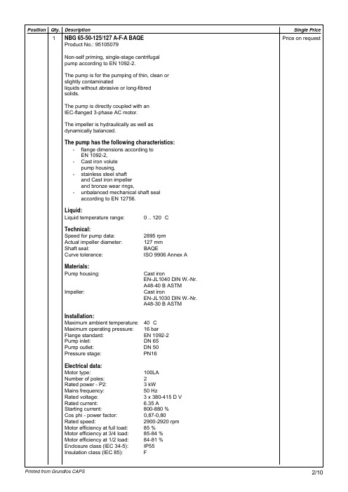
Cast iron EN-JL1040 DIN W.-Nr. A48-40 B ASTM Cast iron EN-JL1030 DIN W.-Nr. A48-30 B ASTM A
10 8 6 4 2 0 0 P (kW) 3 5 10 15 20 25 Eta pump = 68.7 % Eta pump+motor = 58.4 % 30 35 40 45 Q(m³/h
0 .. 120 °C
2895 rpm 127 mm BAQE ISO 9906 Annex A
Impeller:
Cast iron EN-JL1040 DIN W.-Nr. A48-40 B ASTM Cast iron EN-JL1030 DIN W.-Nr. A48-30 B ASTM
Installation: Maximum ambient temperature: Maximum operating pressure: Flange standard: Pump inlet: Pump outlet: Pressure stage: Electrical data: Motor type: Number of poles: Rated power - P2: Mains frequency:
3 x 380-415 D V 6.35 A 800-880 % 0,87-0,80 2900-2920 rpm 85 % 85-84 % 84-81 % IP55 F
56.7 kg
;
Printed from Grundfos CAPS
5/10
Description Product name: Product No: EAN number: Technical: Speed for pump data: Actual impeller diameter: Shaft seal: Curve tolerance: Pump version: Materials: Pump housing:
西门子伺服电机选型手册

西门子伺服电机选型手册
伺服电机具有平滑的旋转特性、优秀的加速能力以及高可靠性。
搭配内置编码器可以实现高精度定位与控制,在非标设备领域应用非常广。
伺服电机的选择主要是对进给轴驱动电机的选择。
基于伺服电机的精度、负载、快速移动的速度、系统的最小进给单位以及其他因素进行综合的考虑,从而得出正确的选择。
在机械加工中,电机所受的力包括:连续负载扭矩(包括重力、摩擦力等)、加减速扭矩、切
削扭矩。
在选择电机时,需要对上述各个力的大小进行综合的分析,最终确定电机的型号。
除此以外,电机在工作的过程中,由于会受到工作环境的影响。
因此,在选择电机的时候,还
需要考虑电机所处的环境对电机的影响,例如:温度、湿度、震动等因素。
影响电机选择的因素
为设备选择进给驱动电机时,需要考虑机械部分的传动结构与电机的匹配、电机的运转速
度、设备的加减速时间大小、电机的停止距离等因素。
概括言之,即
选择与机械相匹配的电机,主要包括以下因素:
1、负载惯量比;
2、加减速特性(短时加工因素;
3、连续负载扭矩;
4、电机速度;
5、扭矩的均方根值;
6、动态刹车距离。
需要注意的是,需要通过正确的计算方法,对电机进行选择。
除了对电机大小的选择以外,在选择电机的过程中,还必须要考虑电机的工作环境。
例如:
高温、高涨度、粉生等因素。
这样就需要对电机的防护等级进行选择。
下面就针对上述的各个因素进行说明。
伺服电机分类与选型流程
伺服电机分类与选型流程伺服电机定义:伺服电机定义伺服电机是指控制伺服系统机械部件运行的发动机,是辅助电机的间接变速装置。
根据电源的不同,分为直流伺服电机和交流伺服电机。
伺服电机的选择应考虑负载机构、动作方式、负载惯性、定位精度、使用环境等。
伺服电机分类与选型流程?一、伺服电机分类伺服电机定义:伺服电机定义伺服电机是指控制伺服系统中机械部件运行的发动机,是辅助电机的间接变速装置。
它分为直流伺服电机和交流伺服电机。
它们在功能上的区别:交流伺服更好,因为它是由正弦波控制的,并且具有较小的转矩波动。
直流伺服为梯形波。
但是直流伺服系统相对简单且便宜。
看到这里,你可能会认为伺服电机没有任何特点:简单来说,伺服电机可以实现精确控制。
它还将反馈尽可能多的信息,以实现所谓的闭环。
编码器会反馈,看看它是否真的旋转了这么多,所以控制精度更高普通电动机通电时转动,不通电时停止。
除了转弯,如果它有任何功能,它是积极的和消极的。
二、提供伺服电机选择流程 1.负载机构(确定机构类型及其详细数据,如滚珠丝杠长度、滚珠丝杆直径、行程、滑轮直径等) 2.动作模式(确定控制对象的动作模式,时间与速度的关系;将控制对象的运动模式转换为电机轴上的动作模式;确定操作模式,包括加速时间(ta)、匀速时间(tu)、减速时间(td)、停止时间(ts)、循环时间(tc)、运动距离(L)等参数) 3.定位精度(确认编码器脉冲数是否满足系统要求的分辨率)伺服电机分类与选型流程?伺服电机由带刷直流电机驱动。
直流电机比交流电机更容易控制,体积更小,价格低廉,因此以前广泛使用。
然而,随着价格的降低,随着电机控制技术的发展,交流使用电机的机会越来越少。
伺服电机及选型完整版

伺服电机及选型HEN system office room 【HEN16H-HENS2AHENS8Q8-HENH1688】伺服电机伺服电机(servomotor)是指在伺服系统中控制机械元件运转的发动机。
伺服电机可以控制速度,位置精度非常准确,可以将电压信号转化为转矩和转速以驱动控制对象。
伺服电机转子转速受输入信号控制,并能快速反应,在自动控制系统中,用作执行元件,可把所收到的转换成电动机轴上的角位移或输出。
“伺服”一词源于希腊语“奴隶”的意思,“伺服电机”可以理解为绝对服从控制信号指挥的电机:在控制信号发出之前,转子静止不动,当控制信号发出时,转子立即转动;当控制信号消失时,转子能即时停转。
因此伺服电机指的是随时跟随命令进行动作的一种电机,是以其工作性质命名的。
伺服主要靠脉冲来定位,伺服电机接收到一个脉冲就会旋转一个脉冲对应的角度,从而实现位移。
伺服本身带有编码器,具备发出脉冲的功能,所以伺服电机每旋转一个角度,就会发出对应数量的脉冲。
等于是把电机旋转的详细信息反馈回去,形成闭环。
这样的话,系统就会知道发了多少脉冲给电机,同时又收了多少脉冲回来,这样就能很精准的控制电机的转动,实现非常精准的定位。
一、伺服电机分类1、直流伺服结构简单控制容易。
但从实际运行考虑,直流伺服电动机引入了机械换向装置,成本高,故障多,维护困难,经常因碳刷产生的火花影响生产,会产生电磁干扰。
而且碳刷需要维护更换。
机械换向器的换向能力,也限制了电动机的容量和速度。
2、交流伺服分为永磁同步伺服电机和异步伺服电机。
目前运动控制基本都用同步电机。
永磁同步伺服电机内部的转子是永磁铁,驱动器控制的U/V/W 三相电形成电磁场,转子在此磁场的作用下转动,同时电机自带的编码器反馈信号给驱动器,驱动器根据反馈值与目标值进行比较,调整转子转动的角度。
伺服电机的精度决定于编码器的精度(线数)。
特点如下:1、控制速度非常快,从启动到额定转速只需几毫秒;而相同情况下异步电机却需要几秒钟。
格兰泰科(Glentek)美国伺服电机选型手册
无刷伺服放大器型号编号. . . . . . . . . . . . . . . . . . . . . . . . . . . . . . . . . . . .Page 7
模拟有刷伺服放大器 . . . . . . . . . . . . . . . . . . . . . . . . . . . . . . . . . . . . . Page 8
Glentek销售团队的话 . . . . . . . . . . . . . . . . . . . . . . . . . . . . . . . . . . . . . ….Page 4
伺服放大器
Omega 系列数字无刷伺服放大器 . . . . . . . . . . . . . . . . . . . . . . . . . . . . . . . . Page 5-6
80 年代,伺服放大器工商业得到了持续发展,包括生产定制的 CAT 扫描伺服放大器和伺服电机设计和生产上的突 飞猛进。在 80 年代中期,将引领尖端技术的承诺作为动力,Glentek 发展了对数字无刷伺服放大器和无刷电机的设计 并将资金投资用于生产低成本的无刷电机。
到了 90 年代,由于同半导体业的紧密联系,“.com”的广泛应用推动了 Glentek 的持续扩张。基于数字 DSP 的放 大器同 Motion Maestro 应用软件被开发。发展一直持续到了进入 21 世纪,2003 年出现了以太网系列通讯兼容的无刷 伺服放大器。这些放大器的性能中含有的插补的正弦波编码器信号可以将定位精确到 1.25µm。2005 年,Glentek 成功 的通过了 ISO9001:2000 认证。
定制设计
Glentek 擅长于为大中型规模的应用定制伺服电机,放大器和运动控制器的设计,并且提供客户品牌商标。对现有 产品的一个简单的修改,就可以满足您对系统的要求,让您节省了大量的时间和精力。
美国电驱284468产品说明书

Eaton 284468Eaton Moeller series NZM - Molded Case Circuit Breaker. Circuit-breaker, 3p, 450A, N3-ME450General specificationsEaton Moeller series NZM molded case circuit breaker electronic284468NZMN3-ME4504015082844684166 mm 275 mm 140 mm 7.07 kg RoHS conformIEC/EN 60947 IECProduct NameCatalog NumberModel Code EANProduct Length/Depth Product Height Product Width Product Weight Compliances Certifications450 AIs the panel builder's responsibility. The specifications for the switchgear must be observed.5 kA35 kAMeets the product standard's requirements.Is the panel builder's responsibility. The specifications for the switchgear must be observed.FixedBuilt-in device fixed built-in technique450 ADoes not apply, since the entire switchgear needs to be evaluated.Max. 10 segments of 24 mm x 1 mm + 5 segments of 24 mm x 1 mm at box terminalMin. 6 segments of 16 mm x 0.8 mm at box terminalMin. 6 segments of 16 mm x 0.8 mm at rear-side connection (punched)10 segments of 50 mm x 1 mm (2x) at rear-side width extension Max. 8 segments of 24 mm x 1 mm (2x) at box terminalMax. 10 segments of 32 mm x 1 mm + 5 segments of 32 mm x 1 mm at rear-side connection (punched)Rocker leverMeets the product standard's requirements.eaton-feerum-the-whole-grain-solution-success-story-en-us.pdfeaton-digital-nzm-brochure-br013003en-en-us.pdfeaton-digital-nzm-catalog-ca013003en-en-us.pdfDA-DC-03_N3eaton-circuit-breaker-nzm-mccb-characteristic-curve-056.epseaton-circuit-breaker-let-through-current-nzm-mccb-characteristic-curve-006.epseaton-circuit-breaker-nzm-mccb-characteristic-curve-017.epseaton-circuit-breaker-nzm-mccb-dimensions-020.epseaton-circuit-breaker-switch-nzm-mccb-dimensions-016.epseaton-circuit-breaker-switch-nzm-mccb-3d-drawing-002.epseaton-general-ie-ready-dilm-contactor-standards.epsMN3-ME450IL01208009ZThe new digital NZM RangeIntroduction of the new digital circuit breaker NZMDA-CS-nzm3_3pDA-CD-nzm3_3peaton-nzm-technical-information-sheeteaton-manual-motor-starters-starter-nzm-mccb-wiring-diagram.eps eaton-manual-motor-starters-starter-msc-r-reversing-starter-wiring-diagram.epsRated operational current for specified heat dissipation (In) 10.11 Short-circuit ratingRated short-circuit breaking capacity Ics (IEC/EN 60947) at 690 V, 50/60 HzRated short-circuit breaking capacity Icu (IEC/EN 60947) at 400/415 V, 50/60 Hz10.4 Clearances and creepage distances10.12 Electromagnetic compatibilityMounting MethodAmperage Rating10.2.5 LiftingTerminal capacity (copper strip)Handle type10.2.3.1 Verification of thermal stability of enclosuresAmbient storage temperature - min BrochuresCatalogs Certification reports Characteristic curveDrawingseCAD model Installation instructions Installation videos mCAD model Technical data sheets Wiring diagrams40 °CFitted with:Thermal protectionProtection against direct contactFinger and back-of-hand proof to VDE 0106 part 100Terminal capacity (copper busbar)M10 at rear-side screw connectionMax. 10 mm x 50 mm (2x) at rear-side width extensionMax. 30 mm x 10 mm + 30 mm x 5 mm direct at switch rear-side connectionMin. 20 mm x 5 mm direct at switch rear-side connection10.8 Connections for external conductorsIs the panel builder's responsibility.Special featuresIEC/EN 60947-4-1, IEC/EN60947-2The circuit-breaker fulfills allrequirements for AC-3switching category.R.m.s. value measurementand “thermal memory”Adjustable time delay settingto overcome current peaks trat 6 x Ir also infinity (withoutoverload releases)All AC-3 rating data appliesto direct switching by thecircuit-breaker under normaloperating conditions. If, forexample, a contactor takesover AC-3 switching undernormal operating conditions,the full rated uninterruptedcurrent applies to the circuit-breaker, In = Iu.Maximum back-up fuse, ifthe expected short-circuitcurrents at the installationlocation exceed theswitching capacity of thecircuit breaker (Rated short-circuit breaking capacity Icn)Rated current = rateduninterrupted current: 450 ATerminal capacity hint: Up to240 mm² can be connecteddepending on the cablemanufacturer.Ambient operating temperature - max70 °CClimatic proofingDamp heat, constant, to IEC 60068-2-78Damp heat, cyclic, to IEC 60068-2-30Terminal capacity (aluminum stranded conductor/cable)25 mm² - 120 mm² (2x) direct at switch rear-side connection 25 mm² - 120 mm² (1x) direct at switch rear-side connection 25 mm² - 185 mm² (1x) at tunnel terminal50 mm² - 240 mm² (1x) at 2-hole tunnel terminal50 mm² - 240 mm² (2x) at 2-hole tunnel terminalTerminal capacity (copper stranded conductor/cable)50 mm² - 240 mm² (2x) at 2-hole tunnel terminal25 mm² - 120 mm² (2x) at box terminal35 mm² - 240 mm² (1x) at box terminal25 mm² - 240 mm² (2x) direct at switch rear-side connection 16 mm² - 185 mm² (1x) at 1-hole tunnel terminal25 mm² - 240 mm² (1x) direct at switch rear-side connectionLifespan, electrical5000 operations at 400 V AC-12000 operations at 400 V AC-32000 operations at 415 V AC-33000 operations at 690 V AC-15000 operations at 415 V AC-12000 operations at 690 V AC-3Electrical connection type of main circuitScrew connectionShort-circuit total breaktime< 10 msRated impulse withstand voltage (Uimp) at main contacts 8000 VRated short-circuit breaking capacity Ics (IEC/EN 60947) at 400/415 V, 50/60 Hz35 kA10.9.3 Impulse withstand voltageIs the panel builder's responsibility.Utilization categoryA (IEC/EN 60947-2)Number of polesThree-poleAmbient operating temperature - min-25 °C10.6 Incorporation of switching devices and componentsDoes not apply, since the entire switchgear needs to be evaluated.10.5 Protection against electric shockDoes not apply, since the entire switchgear needs to be evaluated.Terminal capacity (control cable)0.75 mm² - 1.5 mm² (2x)0.75 mm² - 2.5 mm² (1x)Equipment heat dissipation, current-dependent60.75 WInstantaneous current setting (Ii) - min450 A10.13 Mechanical functionThe device meets the requirements, provided the information in the instruction leaflet (IL) is observed.10.2.6 Mechanical impactDoes not apply, since the entire switchgear needs to be evaluated.10.9.4 Testing of enclosures made of insulating materialIs the panel builder's responsibility.Rated operational current437 A (400 V AC-3)446 A (690 V AC-3)Rated short-circuit breaking capacity Ics (IEC/EN 60947) at 230 V, 50/60 Hz85 kAApplicationUse in unearthed supply systems at 690 V10.3 Degree of protection of assembliesDoes not apply, since the entire switchgear needs to be evaluated.Rated short-circuit making capacity Icm at 240 V, 50/60 Hz187 kARated short-circuit breaking capacity Ics (IEC/EN 60947) at 440V, 50/60 Hz35 kADegree of protection (IP), front sideIP40 (with insulating surround)IP66 (with door coupling rotary handle)Rated short-circuit making capacity Icm at 525 V, 50/60 Hz53 kARated short-circuit making capacity Icm at 690 V, 50/60 Hz40 kAInstantaneous current setting (Ii) - max6300 AOverload current setting (Ir) - min225 A10.2.3.2 Verification of resistance of insulating materials to normal heatMeets the product standard's requirements.10.2.3.3 Resist. of insul. mat. to abnormal heat/fire by internal elect. effectsMeets the product standard's requirements.Lifespan, mechanical15000 operationsOverload current setting (Ir) - max450 AVoltage rating690 V - 690 VTerminal capacity (copper solid conductor/cable)16 mm² (1x) at tunnel terminal16 mm² (1x) direct at switch rear-side connection16 mm² (2x) direct at switch rear-side connection300 mm² (2x) at rear-side width extension16 mm² (2x) at box terminalDegree of protection (terminations)IP10 (tunnel terminal)IP00 (terminations, phase isolator and strip terminal)10.9.2 Power-frequency electric strengthIs the panel builder's responsibility.Short-circuit release non-delayed setting - min900 ADegree of protectionIP20 (basic degree of protection, in the operating controls area)Overvoltage categoryIIIRated short-time withstand current (t = 1 s)3.3 kARated impulse withstand voltage (Uimp) at auxiliary contacts 6000 VTerminal capacity (aluminum solid conductor/cable)16 mm² (1x) at tunnel terminal16 mm² (1x) direct at switch rear-side connection10 mm² - 16 mm² (2x) direct at switch rear-side connectionSwitch off techniqueElectronicRated short-time withstand current (t = 0.3 s)3.3 kAAmbient storage temperature - max70 °CRated short-circuit breaking capacity Ics (IEC/EN 60947) at 525 V, 50/60 Hz13 kAOptional terminalsBox terminal. Connection on rear. Tunnel terminalRelease systemElectronic releasePollution degree310.7 Internal electrical circuits and connectionsIs the panel builder's responsibility.Rated operating power at AC-3, 230 V132 kW10.10 Temperature riseThe panel builder is responsible for the temperature rise calculation. Eaton will provide heat dissipation data for the devices.FunctionsMotor protectionPhase failure sensitiveShort-circuit release non-delayed setting - maxStandard terminalsScrew terminalRated short-circuit making capacity Icm at 400/415 V, 50/60 Hz 105 kARated operating power at AC-3, 400 V250 kWTypeCircuit breaker10.2.2 Corrosion resistanceMeets the product standard's requirements.10.2.4 Resistance to ultra-violet (UV) radiationMeets the product standard's requirements.10.2.7 InscriptionsMeets the product standard's requirements.Rated short-circuit making capacity Icm at 440 V, 50/60 Hz74 kAIsolation500 V AC (between auxiliary contacts and main contacts)300 V AC (between the auxiliary contacts)Number of operations per hour - max60Circuit breaker frame typeNZM3Direction of incoming supplyAs requiredShock resistance20 g (half-sinusoidal shock 20 ms)Rated insulation voltage (Ui)1000 VEaton Corporation plc Eaton House30 Pembroke Road Dublin 4, Ireland © 2023 Eaton. All Rights Reserved. Eaton is a registered trademark.All other trademarks areproperty of their respectiveowners./socialmedia。
伺服电机的选型步骤及注意事项

伺服电机的选型步骤及注意事项欢迎加入圈子学习更多的伺服控制技术和经验伺服电机是指在伺服系统中控制机械元件运转的发动机,是一种补助马达间接变速装置。
每种型号伺服电机的规格项内均有额定转矩、最大转矩及伺服电机惯量等参数各参数与负载转矩及负载惯量间必定有相关联系存在,选用伺服电机的输出转矩应符合负载机构的运动条件要求,如加速度的快慢、机构的重量;机构的运动方式(水平、垂直旋转)等;运动条件与伺服电机输出功率无直接关系,但是一般伺服电机输出功率越高,相对输出转矩也会越高。
因此不但机构重量会影响伺服电机的选用,运动条件也会改变伺服电机的选用。
惯量越大时,需要越大的加速及减速转矩,加速及减速时间越短时,也需要越大的伺服电机输出转矩。
选用伺服电机规格时,依下列步骤进行。
一、伺服电机的选型步骤1、明确负载机构的运动条件要求,即加/减速的快慢、运动速度、机构的重量、机构的运动方式等。
2、依据运行条件要求选用合适的负载惯量计算公式计算出机构的负载惯量。
3、依据负载惯量与伺服电机惯量选出适当的假选定伺服电机规格。
4、结合初选的伺服电机惯量与负载惯量,计算出加速转矩及减速转矩。
5、依据负载重量、配置方式、摩擦系数、运行效效率计算出负载转矩。
6、初选伺服电机的最大输出转矩必须大于加速转矩+负载转矩;如不符合条件,必须选用其他型号计算验证直至符符合要求。
7、依据负载转矩、加速转矩、减速转矩及保持转矩计算出连续瞬时转矩。
8、初选伺服电机的额定转矩必须大于连续瞬时转矩,如,如果不符合条件,必须选用其他型号计算验证直至符合要求。
9、完成选定。
二、伺服电机选型的注意事项1、如果选择了带电磁制动器的伺服电机,电机的转动惯量会增大,计算转矩时要进行考虑。
2、有的伺服驱动器有内置的再生制动单元,但当再生制动较频繁时,可能引起直流母线电压过高,这时需另配再生制动电阻。
再生制动电阻是否需要另配,配多大,可参照相应样本的使用说明来配。
3、有些系统要维持机械装置的静止位置,需电机提供较大的输出转矩,且停止的时间较长。
伺服电机的选择
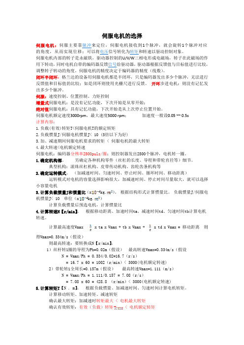
伺服电机的选择伺服电机:伺服主要靠脉冲来定位,伺服电机接收到1个脉冲,就会旋转1个脉冲对应的角度,从而实现位移;可以将电压信号转化为转矩和转速以驱动控制对象。
伺服电机内部的转子是永磁铁,驱动器控制的U/V/W三相电形成电磁场,转子在此磁场的作用下转动,同时电机自带的编码器反馈信号给驱动器,驱动器根据反馈值与目标值进行比较,调整转子转动的角度。
伺服电机的精度决定于编码器的精度(线数)。
闭环半闭环:格兰达的设备用伺服电机都是半闭环,只是编码器发出多少个脉冲,无法进行反馈值和目标值的比较;如是闭环则使用光栅尺进行反馈。
开环步进电机:则没有记忆发出多少个脉冲。
伺服:速度控制、位置控制、力矩控制增量式伺服电机:是没有记忆功能,下次开始是从零开始;绝对值伺服电机:具有记忆功能,下次开始是从上次停止位置开始。
伺服电机额定速度3000rpm,最大速度5000 rpm;加速度一般设0.05 ~~ 0.5s计算内容:1.负载(有效)转矩T<伺服电机T的额定转矩2.负载惯量J/伺服电机惯量J< 10 (5倍以下为好)3.加、减速期间伺服电机要求的转矩 < 伺服电机的最大转矩4.最大转速<电机额定转速伺服电机:编码器分辨率2500puls/圈;则控制器发出2500个脉冲,电机转一圈。
1.确定机构部。
另确定各种机构零件(丝杠的长度、导程和带轮直径等)细节。
典型机构:滚珠丝杠机构、皮带传动机构、齿轮齿条机构等2.确定运转模式。
(加减速时间、匀速时间、停止时间、循环时间、移动距离)运转模式对电机的容量选择影响很大,加减速时间、停止时间尽量取大,就可以选择小容量电机3.计算负载惯量J和惯量比(x kg.)。
根据结构形式计算惯量比。
负载惯量J/伺服电机惯量J< 10 单位(x kg.)计算负载惯量后预选电机,计算惯量比4.计算转速N【r/min】。
根据移动距离、加速时间ta、减速时间td、匀速时间tb计算电机转速。
Glenair ATS标准带选型指南说明书

The Advanced Termination System for Interconnect Cable ShieldingEasy-to-use manual tools with built-in calibration counterHigh-volume pneumatic toolfor bench use 3 lengths and 3 widths of EMI braid termination bandsAPRIL 20152© 2014 Glenair, Inc • 1211 Air Way, Glendale, CA 91201 • 818-247-6000 • • U.S. CAGE code 06324 Dimensions in Inches(mm)Band-Master™ ATS Standard Band SelectionLength Part NumberFits DiameterBandsIn.mm.Flat Pre-Coiled In.mm.Short Standard 9.0228.6601-005601-006 1.025.4Medium Standard 14.25361.95601-040601-041 1.845.7Long Standard18.0457.2601-049601-0502.563.5Cable Pull Strength for BandMaster™ ATS Standard BandsName Material Type Band WidthBand ThicknessCalibrationSetting Cable Pull Strength In mm In mm Standard304 SS0.240 6.10.020.51150 ±5 lbsper AS85049/128The 601-100 Band-Master™ ATS Standard Tool with Counter for Standard BandsWeighs 1.2 lbs., and is designed for .240" width clamping bands in a tension range from 100 to 180 lbs. Calibrate at 150 lbs. ± 5 lbs. for most shield terminations. Tool and band should never be lubricated.The 600-058 QPL Qualified (M81306/1A) Standard Banding Tool without CounterWeighs 1.1 and is designed for .240” width clamping bands in a tension range from 100 to 180 lbs. Calibrate at 150 lbs. ± 5 lbs. for most shield terminations. Tool and band should never be lubricated (not shown).Manual Tools and BandsStandard Banding ToolColor-coded tool handle:QPL Qualifiied Standard Band SelectionLength Mil Spec Part Number Fits DiameterBandsin.mm.Flat Pre-Coiled in.mm.Standard Band14.25361.95M85049/128-3M85049/128-41.845.7Cable Pull Strength for Standard QPL Qualified BandsName Material Type Band WidthBand ThicknessCalibrationSetting Cable Pull Strength In mm In mm Standard304 SS0.240 6.10.020.51150 ±5 lbsper AS85049/128= Standard; Black3© 2014 Glenair, Inc • 1211 Air Way, Glendale, CA 91201 • 818-247-6000 • • U.S. CAGE code 06324 Dimensions in Inches(mm)Medium Flat 601-040Medium Precoiled 601-041Standard bands are precision constructed of 300 Series SST/Passivate. Medium standard bands are 14.25inches (361.95) in length and designed for use with the Band-Master™ ATS 601-100 manual banding tool or the 601-104 pneumatic banding tool. Bands should always be double wrapped and will accommodate diameters up to approximately 1.8 inches (45.7).Long Flat 601-049Long Precoiled 601-050Standard bands are precision constructed of 300 Series SST/Passivate. Long standard bands are 18.0 inches (457.2) in length and designed for use with the Band-Master™ ATS 601-100 manual banding tool or the 601-104 pneumatic banding tool. Bands should always be double wrapped and will accommodate diameters up to approximately 2.5 inches (63.5).Short Flat 601-005Short Precoiled 601-006Standard bands are precision constructed of 300 Series SST/Passivate. Short standard bands are 9.00 inches (228.6) in length and designed for use with the Band-Master™ ATS 601-100 manual banding tool or the 601-104 pneumatic banding tool.Bands should always be double wrapped and will accommodate diameters up to approximately 1.0 inches (25.4).Standard Bands9.0 ± .030(228.6 ± 0.8)Tail Length Indicator Mark.350 (8.9) Ref..020 (0.5) Ref..156 (4.0) Ref..074 (1.9) Ref..240 (6.1) Ref.Tail Length Indicator Mark.350 (8.9) Ref..020 (0.5) Ref..156 (4.0) Ref..074 (1.9) Ref..240 (6.1) Ref.18.0 ± .060(457.2 ± 1.5)14.25 ± .060(361.95 ± 1.5)Tail Length Indicator Mar k.350 (8.9) Ref..020 (0.5) Ref..156 (4.0) Ref..074 (1.9) Ref..240 (6.1) Ref.4© 2014 Glenair, Inc • 1211 Air Way, Glendale, CA 91201 • 818-247-6000 • • U.S. CAGE code 06324 Dimensions in Inches(mm)Band-Master™ ATS Micro Band SelectionLength Part Number Fits DiameterBandsin.mm.Flat Pre-Coiled in.mm.Short Micro 5.0127.0601-024601-0250.512.7Medium Micro 8.125206.38601-060601-061.8822.4Long Micro14.25361.95601-064601-0651.845.7Cable Pull Strength for Band-Master™ ATS Micro BandsName Material Type Band WidthBand ThicknessCalibrationSetting Cable Pull Strength In mm In mm Micro304 SS0.120 3.05.015.3880 ±5 lbsper AS85049/128The 601-101 Band-Master™ ATS Micro Tool with Counter for Micro BandsWeighs 1.3 lbs., and is designed for micro .120" width clamping bands in a tension range from 50 to 85 lbs. Calibrate at 80 lbs ±3 lbs. for most shield terminations. Tool and band should never be lubricated.The 600-061 QPL Qualified (M81306/1B) Micro Banding Tool without CounterWeighs 1.1 and is designed for micro .120” width clamping bands in a tension range from 60 to 85 lbs. Calibrate at 80 lbs ±5 lbs. for most shield terminations. Tool and band should never be lubricated (not shown).Manual Tools and BandsMicro Banding ToolColor-coded tool handle:QPL Qualified Micro Band SelectionLength Part Number Fits DiameterBandsin.mm.Flat Pre-Coiled in.mm.Standard Micro8.125206.38M85049/128-7M85049/128-8.8822.4Cable Pull Strength for Micro QPL Qualified BandsName Material Type Band WidthBand ThicknessCalibrationSetting Cable Pull Strength In mm In mm Micro304 SS0.120 3.05.015.3880 ±5 lbsper AS85049/128= Micro; Blue5© 2014 Glenair, Inc • 1211 Air Way, Glendale, CA 91201 • 818-247-6000 • • U.S. CAGE code 06324 Dimensions in Inches(mm)Long Flat 601-064Long Precoiled 601-065Micro Bands are precision constructed of 300 Series SST. Long Micro Bands are 14.00 inches (355.6) in length and designed for use with the Band-Master™ 601-101 hand banding tool or the 601-105 pneumatic banding tool. Bands should always be double wrapped and will accommodate diameters up to approximately 1.88 inches (47.8).Medium Flat 601-060Medium Precoiled 601-061Micro Bands are precision constructed of 300 Series SST. Medium micro bands are 8.00 inches (203.2) in length and designed for use with the Band-Master™ 601-101 hand banding tool or the 601-105 pneumatic banding tool. Bands should always be double wrapped and will accommodate diameters up to approximately .88 inches (22.4).Short Flat 601-024Short Precoiled 601-025Micro Bands are precision constructed of 300 Series SST. Short micro bands are 5.00 inches (127) in length and designed for use with the Band-Master™ 601-101 hand banding tool or the 601-105 pneumatic banding tool. Bands should always be double wrapped and will accommodate diameters up to approximately .5 inches (12.7).Micro BandsTail Length Indicator Mark.195 (5.0) Ref..015 (0.4) Ref.5.0 ± .030(127 ± 0.8).090 (2.3) Ref..053 (1.9) Ref..120 (3.0) Ref.Tail Length Indicator Mark.195 (5.0) Ref..015 (0.4) Ref.8.125 ± .030(206.4 ± 0.8).090 (2.3) Ref..053 (1.9) Ref..120 (3.0) Ref..120 (3.0) Ref.Tail Length Indicator Mark.195 (5.0) Ref..015 (0.4) Ref.14.25 ± .030(362.0 ± 0.8).090 (2.3) Ref..053 (1.9) Ref.6© 2014 Glenair, Inc • 1211 Air Way, Glendale, CA 91201 • 818-247-6000 • • U.S. CAGE code 06324 Dimensions in Inches(mm)Band-Master™ ATS Nano Band SelectionLength Part NumberFits DiameterBandsin.mm.Flat Pre-Coiled in.mm.Short Nano 6.0152.4601-500601-501.6015.2Medium Nano 9.0228.6601-504601-505.9423.9Long Nano14.0355.6601-508601-5091.845.7The 601-108 Band-Master™ ATS Nano Tool with Counter for Nano BandsWeighs 1.2 lbs., and is designed for nano flat .075" width clamping bands in a tension range from 20 to 50 lbs. Calibrate at 50 lbs. ± 3 lbs. for most shield terminations. Tool and band should never be lubricated.Manual Tools and BandsNano Banding ToolCable Pull Strength for Band-Master™ ATS Nano BandsName Material Type Band WidthBand ThicknessTool Setting Cable PullStrength In.mm.In.mm.Nano304 SS0.075 1.91.009.2350 ±3 lbs50 lbs** Nano Bands are work hardened to achieve higher cable pull forceColor-coded tool handle:= Nano; Green7© 2014 Glenair, Inc • 1211 Air Way, Glendale, CA 91201 • 818-247-6000 • • U.S. CAGE code 06324 Dimensions in Inches(mm)Medium Flat 601-504Medium Precoiled 601-505Nano Bands are precision constructed of workhardened, 300 Series SST for improved performance. Medium nano bands are 9.00 inches (228.6) in length and designed for use with the 601-108 Band-Master™ ATS hand banding tool. Bands should always bedouble wrapped and will accommodate diameters up to approximately .94 inches (23.9).Short Flat 601-500Short Precoiled 601-501Nano Bands are precision constructed of workhardened, 300 Series SST for improved performance. Short nano bands are 6.00 inches (152.4) in length and designed for use with the 601-108 Band-Master™ ATS hand banding tool. Bands should always bedouble wrapped and will accommodate diameters up to approximately .60 inches (15.2).Long Flat 601-508Long Precoiled 601-509Nano Bands are precision constructed of workhardened, 300 Series SST for improved performance. Long nano bands are 14.25 inches (361.95) in length and designed for use with the 601-108 Band-Master™ ATS hand banding tool. Bands should always bedouble wrapped and will accommodate diameters up to approximately 1.8 inches (45.7).Nano BandsTail Length Indicator Mark.124 (3.1) Ref..009 (0.2) Ref.6.0 ± .030(152.4 ± 0.8).056 (2.29) Ref..038 (0.9) Ref..075 (1.9) Ref.Tail Length Indicator Mark.124 (3.1) Ref..009 (0.2) Ref.9.0 ± .030(228.6 ± 0.8).038 (0.9) Ref..075 (1.9) Ref..056 (2.29) Ref.Tail Length Indicator Mark.124 (3.1) Ref..009 (0.2) Ref.14.00 ± .030(361.95 ± 0.8).038 (0.9) Ref..075 (1.9) Ref..056 (2.29) Ref.8© 2014 Glenair, Inc • 1211 Air Way, Glendale, CA 91201 • 818-247-6000 • • U.S. CAGE code 06324 Dimensions in Inches(mm)Band-Master™ ATS Slim Band SelectionLength Part Number Fits DiameterBandsin.mm.Flat Pre-Coiled in.mm.Short Slim Standard 9.0228.6601-570601-571.9423.9Medium Slim Standard14.25361.95601-572601-5731.845.7The 601-109 Band-Master™ ATS Slim Tool with Counter for Slim Bandsweighs 1.2 lbs., and is designed for slim standard flat .24" width clamping bands in atension range from 50 to 100 lbs. Calibrate at 100 lbs. ± 3 lbs. for most shield terminations. Tool and band should never be lubricated.Choose Glenair Slim Bands for size and weightsavings. Slim bands are 50% lighter with 50% lower profile than our standard bands, while maintaining similar performance.Manual Tools and BandsSlim Banding ToolCable Pull Strength for Band-Master™ ATS Slim Standard BandsName Material Type Band WidthBand ThicknessTool Setting Cable PullStrength In mm In mm Slim Standard300 Series SST0.240 6.09.010.25100 lbs. ± 3 lbs.150 lbs.** Slim Bands are work hardened to achieve higher cable pull forceColor-coded tool handle= Slim Standard; Orange9© 2014 Glenair, Inc • 1211 Air Way, Glendale, CA 91201 • 818-247-6000 • • U.S. CAGE code 06324 Dimensions in Inches(mm)Medium Flat 601-572Medium Precoiled 601-573Slim Standard Bands are 50% lighter and 50%lower-profile than standard bands. They are precision constructed of work hardened, 300 Series SST for improved performance. Medium slim bands are 14.25 inches (228.6) in length and designed for use with the 601-109 Band-Master™ ATS hand banding tool or the 601-110 pneumatic tool. Bands should always be double wrapped and will accommodate diameters up to approximately 1.8 inches (45.7)Short Flat 601-570Short Precoiled 601-571Slim Standard Bands are 50% lighter and 50% lower-profile than standard bands. They are precision constructed of work hardened, 300 Series SST for improved performance. Short slim bands are 9.00 inches (228.6) in length and designed for use with the 601-109 Band-Master™ ATS hand banding tool or the 601-110 pneumatic tool. Bands should always be double wrapped and will accommodate diameters up to approximately .94 inches (23.9).Slim Standard BandsTail Length Indicator Mark.370 (9.4) Ref..010 (0.3) Ref.9.0 ± .030(228.6 ± 0.8).156 (4.0) Ref..030 (0.7) Ref..240 (6.1) Ref.Tail Length Indicator Mark.370 (9.4) Ref..010 (0.3) Ref.14.25 ± .030(362.0 ± 0.8).156 (4.0) Ref..030 (0.7) Ref..240 (6.1) Ref.10© 2014 Glenair, Inc • 1211 Air Way, Glendale, CA 91201 • 818-247-6000 • • U.S. CAGE code 06324 Dimensions in Inches(mm)601-301 Standard Cutter KnifeThe 601-301 Standard Cutter Knife replaces the cutter knife on the 601-100 Band-Master™ ATS standard manual banding tool and the 601-104 standardpneumatic banding tool. Material is heat treated steel finished with black oxide and rust preventative.601-303 Micro Cutter KnifeThe 601-303 Micro Cutter Knife replaces the cutter knife on the 601-101 Micro Band-Master™ ATS Micro manual banding tool, and the 600-105 pneumaticbanding tool. Material is heat treated steel finished with black oxide and rust preventative..265 (6.7) Dia. Ref..688 (17.5)Ref..690 (17.5).122 (3.1) Dia..246 (6.2) Dia.601-305 Micro Cut-Off Blade KitThe 601-305 Micro Cut-Off Blade Kit consists of the blade, two E-rings and one pin, providing all parts needed to replace the cut-off blade on the 601-101 Micro Band-Master™ ATS manual banding tool and the 601-105 pneumatic micro banding tool. Material is heat treated steel finished with black oxide and rust preventative.Note: E-Rings supplied are for body of tool601-302 Standard Cut-Off Blade KitThe 601-302 Standard Cut-Off Blade Kit consists of the blade, two E-rings and one pin, providing all parts needed to replace the cut-off blade on the 601-100 Band-Master™ ATS standard manual banding tools and the 601-104 standard pneumatic banding tool. Material is heat treated steel finished with black oxide and rust preventative.Note: E-Rings supplied are for body of toolReplacement Parts and Calibration Tools for Manual Banding ToolsCut Off Blade Kits and Knives.335 (8.5)Dia..145 (3.7).025(.64).250 (6.4)1.000 (25.4).270 (6.9).450(11.4).125 (3.2)Dia. Ref.PIN (1 Each)E-RING ( 2 Each).335 (8.5)Dia..145 (3.7).025(.64).250 (6.4)1.000 (25.4).135 (3.4).290(7.4).125 (3.2)Dia. Ref.PIN (1 Each)E-RING ( 2 Each)11© 2014 Glenair, Inc • 1211 Air Way, Glendale, CA 91201 • 818-247-6000 • • U.S. CAGE code 06324 Dimensions in Inches(mm)601-211 and 601-212 Tension GaugeThe 601-211 (M81306/1C) and 601-212 (M81306/1D)Tension Gauge is used to check and calibrate the manual tool to values noted on calibration sticker. Constructed of hardened steel.601-205 Calibration KeyThe 601-205 Calibration Key is designed for use with 600-058, 600-061, 601-211 and 601-212 manual banding tools. Material is black anodized aluminum alloy. One full turn clockwise will advance the tension rangeapproximately 1.0 - 2.5 lbs, a counter-clockwise turn will decrease tension by the same amount.Part No.SAE Part No.(Ref) A+.015 (0.38)-.005 (0.13)Used with ManualTool P/N601-211M81306/1C.460 (11.68)Standard601-100 • 600-058(M81306/1-01 Kit)601-212M81306/1D .360 (9.14)Micro601-101• 600-061(M81306/1-02 Kit)601-205M81306/1EN/A BothCalibration Keys and Tension GaugesØ 1.38 (35.05) MaxAØ .92 (23.37) MaxAbove tolerance limit stripe (not visible when gauge is in the fixed position)Verification inspection indicator windowNote: the band tool is within tolerance if no part of the stripes (above or below) appear in the verification inspection indicator windowBelow tolerance limit stripe (in view when gauge is in the fixed position).50 (12.7)3.00 (76.2)Ref.1.75 (44.5)Ref.12© 2014 Glenair, Inc • 1211 Air Way, Glendale, CA 91201 • 818-247-6000 • • U.S. CAGE code 06324 Dimensions in Inches(mm)601-400 Foot Pedal Control for 601-104, 601-105 and 601-118 Pneumatic Banding ToolsThe 601-400 Foot Pedal Control frees both hands to help assure more accurate, reliable and faster shield terminations.601-200 Calibration Kit For All Banding ToolsThe 601-200 Calibration Kit includes the (1) 601-200-3 calibration device, (2) fifty 601-203 Micro test bands, (3) fifty 601-202 Standard test bands, (4) fifty 601-217 Nano test bands, (5) 601-205 calibration key, (6) Standard tool adapter 601-218 for 601-100, 600-058 installed (7) Standard Pneumatic tool adapter 601-219 for 600-067, 601-104 (8) Micro tool adapter 601-220 for 601-101, 601-105, 601-108, 600-061, and 600-068 (9) Adjustable mounting bracket for meter (10) Data logging softwareRange of the calibration device is 0 to 500 lbs, and accuracy is calibrated to ±1 lbs. at factory. Digital readout in .1 lb. increments. Metersupplied with RS-232 serial communication port on rear of meter case. Serial/USB adapter cable included.Calibration Kits, Accessories and Pneumatic Banding ToolsCalibration Kits and Accessories1025971683413© 2014 Glenair, Inc • 1211 Air Way, Glendale, CA 91201 • 818-247-6000 • • U.S. CAGE code 06324 Dimensions in Inches(mm)High-Volume Pneumatic Bench-Mount Units and Calibration Kits Available for Standard, Micro and Nano Band Termination Systems601-105 Micro Pneumatic Banding ToolThe 601-105 Micro Pneumatic Banding Tool accommodates 601-024, 601-025, 600-057, 600-059 Micro Bands in a tension range of from 60 to 90 lbs. Calibrate at 80 ± 5 lbs for most shield terminations. Weight of the tool is 2.52 lbs (1.14 Kg); the control box weighs 3.51 lbs (1.59 Kg).601-104 Standard Pneumatic Banding ToolThe 601-104 Standard Pneumatic Banding Toolaccommodates 601-005, 601-006, 601-052 and 601-054 standard bands in a tension range of from 100-180 lbs.Calibrate at 150 ± 5 lbs for most shield terminations. Weight of the tool is 2.52 lbs (1.14 Kg); the control box weighs 3.51 lbs (1.59 Kg).601-118 Nano Pneumatic Banding ToolThe 601-118 Nano Pneumatic Banding Tool accommodates 601-500, 601-501, 601-504, 601-505, 601-508 and 601-509 Nano bands in a tension range of from 30-90 lbs. Calibrate at 50 ± 3 lbs for most shield terminations. Weight of the tool is 2.52 lbs (1.14 Kg); the control box weighs 3.51 lbs (1.59 Kg).Glenair now offers its pneumatic tools and foot pedal control in one easy to order kit. Contact factory for more information.Pneumatic Banding ToolsCover For Foot Pedal Ref. 601-4005.30 Ref8.00 Ref4.00 RefPrecision RegulatorInside Under Clear LensDigital Pressure Gage Inside Under Clear LensBandmaster Pneumatic Tool3.00Ref4.85Ref5.00 RefHose, CoilRegulator Assembly14© 2014 Glenair, Inc • 1211 Air Way, Glendale, CA 91201 • 818-247-6000 • • U.S. CAGE code 06324Dimensions in Inches(mm)Step 3Double-wrap the band prior to use:NOTE: Due to connector/adapter circumference, it may be necessary to double-coil the band in place around the cable or termination area.A. Loop/insert the leading edge of band through the buckle slot twice. (Bands must be double-wrapped.)B. Tighten the coil until the indicator mark ( ) is approximately .250 inches (6.4) shy of the buckle slot (see illustration at left). This will ensure sufficient band tail length for insertion into tool.Buckle.250 in. (6.4 mm)Tail Length Indicator Mark ( )NOTES:1. Use only genuineBand-Master™ ATS bands. Other manufacturer’s bands may damage tool.2. Use only .240" widebands with 601-100 tool and .120" wide bands with 601-101 tool.1 Calibration Access Plug2 Tensioning Lever:Squeeze with short gentle strokes to tighten band to the proper tension. Lever will lock to 3 Handle with final full stroke.4 Cut-Off Lever:Squeeze to lock band buckle and trim excess band material.5 Cycle Counter6 Band Insertion and Release Lever:Depress lever to insert or release band from tool.7 Serial Number8 Tension Release Lever57813246Band-Master ™ ATSShield Termination Assembly ProcessStep 1Prepare Cable Braid for termination processNOTE: Complete banding on an unfixtured cable assembly. Terminating a band to a clamped or fixtured cable will affect the applied forces and interfere with the cut-off operation. The cut-off operation causes a rotation of the band termination in order to lock the band.Step 2Push braid forward over banding platform. Milk braid as required to remove slack and ensure a snug fit around the shield termination area.Video Training Series At:/bandmaster/index.htm15© 2014 Glenair, Inc • 1211 Air Way, Glendale, CA 91201 • 818-247-6000 • • U.S. CAGE code 06324 Dimensions in Inches(mm)Step 4Depress the band insertion and release lever (6), and insert the working end of the band into the front end opening of the tool, with the loop positioned outward as shown.Step 5The band termination area on all backshells is wider than the band. Position the band near the rear lip of the banding platform, allowing room for the buckle. For elliptical cable entries position the buckle off center of the peak of the circle. Failure to follow these guidelines will result in poor performance.Step 6Contract the band with the tensioning lever (2) using short, even strokes. As the band contracts firmly on the termination area, pull a full stroke to lock the lever against the main tool handle which will indicate the band is compressed to the proper tension.NOTE: Overly rapid tightening of the band may result in unevencompression. If alignment of the band and shield is unsatisfactory, tension can be relaxed by pulling up on the tensioning lever (2) and then pushing the tension release lever (8) forward. Make adjustments as necessary and finish tightening with tensioning lever (2) as described above.Step 7Complete the clamping process by depressing the cut-off lever (4), allow-ing band and cable to rotate slightly. Pull up the release lever (6) to remove excess band for disposal.NOTE: Always band on an unfixtured connector/cable assembly.Step 8Trim away excess braid from theforward groove, particularly if a shrink boot is to be applied to the assembly.Step 9Visually inspect shield termination for problems.NOTE: Band can be removed by lifting the buckle with a screwdriver or diagonal cutters.Trim excess braidaway from shrink boot grooveSqueeze the bandinsertion and release leverNot HereFor elliptical adapters, position the buckle Here on the flat portion of the ellipse as shownNot HerePosition the band nearthe rear lip leaving room for buckle.Nicely Done!Interconnect HEAVY-DUTYAssembly ToolsThe right tool for every interconnectassembly requirementGlenair, Inc.1211 Air Way Glendale, CA 91201-2497818-247-6000*****************Interconnect Cable Assembly ToolsBand-It Shield Termination Tools, Connector-to-Backshell Holding Tools, Fiber Optic Termination Kits and More!Glenair offers its connector and connector accessory customers every convenience in the provision of contact termination, shield termination, and backshell-to-connector assembly tooling. We are also proud to offer branded solutions from other well-known tool manufacturers such as Daniels (DMC) crimp tools. From pneumatic Earth-Bond tooling for the rail industry, to fiber optic termination and test equipment, Glenair is your most knowledgeable and reliable source for special-purpose interconnect assembly tooling.BandMaster™ ATS EMI/RFI Shield Termination SystemBackshell-to-ConnectorAssembly ToolsGlenair, Inc.1211 Air Way • Glendale, California • 91201-2497Telephone:818-247-6000•Fax:818-500-9912•*****************Telephone:+44-1623-638100Facsimile:+44-1623-638111****************.uk Glenair UK Ltd40 Lower Oakham Way Oakham Business Park P .O. Box 37, Mansfield Notts, NG18 5BY England Telephone:06172 / 68 16 0Facsimile:06172 / 68 16 90*******************Glenair Electric GmbH Schaberweg 2861348 Bad Homburg GermanyTelephone:+33-5-34-40-97-40Facsimile:+33-5-61-47-86-10****************Glenair France SARL 7, Avenue Parmentier Immeuble Central Parc #231200 Toulouse FranceTelephone:847-679-8833Facsimile:847-679-8849Glenair Microway Systems 7000 North Lawndale Avenue Lincolnwood, IL 60712Telephone:+46-8-50550000****************Glenair Nordic ABGustav III : S Boulevard 46SE-169 27 Solna Sweden© 2015 Glenair, Inc. Printed in U.S.A.Telephone:+34-925-89-29-88Facsimile:+34-925-89-29-87****************Glenair Iberica C/ La Vega, 1645612 Velada SpainTelephone:203-741-1115Facsimile:203-741-0053*****************Glenair Power Products Group860 N. Main Street Extension Wallingford, CT 06492Telephone: +39-051-782811Facsimile:+39-051-782259***************Telephone:+82-31-8068-1090Facsimile:+82-31-8068-1092****************Glenair Italia S.p.A.Via Del Lavoro, 740057 Quarto Inferiore – Granarolo dell’Emilia Bologna, ItalyGlenair KoreaB-1304 Gunpo IT Valley 148 Gosan-Ro, Gunpo-Si Kyunggi-Do, Korea 435-733INTERCONNECT SOLUTIONSOut of This World。
伺服电机选型手册
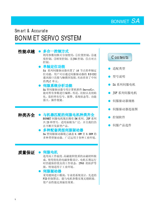
BONMET SA Smart & AccurateBONMET SERVO SYSTEM性能卓越●多合一控制方式利用参数切换可分别使用:①位置控制;②速度控制;③转矩控制;④JOG控制;⑤点对点控制。
●单轴定位功能SA系列伺服驱动器内置了16节点的单轴定位功能,用户可以通过伺服驱动器的RS-232通讯接口直接与触摸屏连接,从而省却了中间的PLC单元。
●伺服系统分析功能SA型伺服驱动器专用计算机软件Servofly,能对所有参数进行编辑、传送、比较以及初始化,监控所有信号、报警、系统状态等,功能强大,操作便捷。
种类齐全●与机器匹配的伺服电机种类齐全BONMET伺服电机现在拥有SM系列、JSF系列共25种型号,适用面极为广泛,并且我们仍在不断开发新型产品。
●多种配套类型伺服驱动器SA型伺服驱动器现已涵盖0.4KW至5.5KW的多种类型驱动器,广泛运用于各种工业环境。
质量保证●伺服电机选用高工作温度、高磁能积优质的永磁材料做成,使用优化的电磁参数设计,电机长期运行时仍能保持优良的工作状态,IP65的防护等级,特别适用于工业环境。
●伺服驱动器采用德国进口模块,专业的系统设计,先进的PID控制算法,能与电机参数实现无缝联接,使产品性能达到最佳效果。
●适配类型●型号说明●SA系列伺服电机●JSF系列伺服电机●伺服驱动器规格●伺服驱动器连接图●控制软件●伺服产品选件Contents●SM系列伺服电机型号说明SM 110 050 30 L F B Z1 2 3 4 5 6 7 81:表示电机是正弦波驱动的永磁同步交流伺服电机。
2:表示电机外径,单位:mm。
3:表示电机零速转矩,其值为三位数×0.1,单位:Nm。
4:表示电机额定转速,其值为二位数×100,单位:rpm。
5:表示电机适配的驱动器工作电压,L—AC220V,H—AC380V。
6:表示反馈元件的规格,F—复合式增量编码器(2500 C/T);F1—省线式增量编码器;R—1对极旋转变压器。
图解伺服电机选型实例

伺服电机计算选择应用实例1. 选择电机时的计算条件 本节叙述水平运动伺服轴(见下图)的电机选择步骤。
例:工作台和工件的 W :运动部件(工作台及工件)的重量(kgf )=1000 kgf 机械规格 μ :滑动表面的摩擦系数=0.05π :驱动系统(包括滚珠丝杠)的效率=0.9 fg :镶条锁紧力(kgf )=50 kgfFc :由切削力引起的反推力(kgf )=100 kgfFcf :由切削力矩引起的滑动表面上工作台受到的力(kgf )=30kgfZ1/Z2: 变速比=1/1例:进给丝杠的(滚珠 Db :轴径=32 mm 丝杠)的规格 Lb :轴长=1000 mmP:节距=8 mm例:电机轴的运行规格 Ta :加速力矩(kgf.cm )Vm :快速移动时的电机速度(mm -1)=3000 mm -1 ta :加速时间(s)=0.10 s Jm :电机的惯量(kgf.cm.sec 2)Jl:负载惯量(kgf.cm.sec 2)ks :伺服的位置回路增益(sec -1)=30 sec -11.1 负载力矩和惯量的计算 计算负载力矩 加到电机轴上的负载力矩通常由下式算出:Tm = + Tf Tm :加到电机轴上的负载力矩(Nm) F :沿坐标轴移动一个部件(工作台或刀架)所需的力(kgf) L :电机转一转机床的移动距离=P ×(Z1/Z2)=8 mmTf:滚珠丝杠螺母或轴承加到电机轴上的摩擦力矩=2Nm无论是否在切削,是垂直轴还是水平轴,F 值取决于工作台的重量,摩擦系数。
若坐标轴是垂直轴,F 值还与平衡锤有关。
对于水平工作台,F 值可按下列公式计算: 不切削时:F = μ(W+fg )例如:F ×L 2πηF=0.05×(1000+50)=52.5 (kgf)Tm = (52.5×0.8) / (2×μ×0.9)+2=9.4(kgf.cm)= 0.9(Nm)切削时:F = Fc+μ(W+fg+Fcf) 例如:F=100+0.05×(1000+50+30)=154(kgf)Tmc=(154×0.8) / (2×μ×0.9)+2=21.8(kgf.cm)=2.1(Nm)为了满足条件1,应根据数据单选择电机,其负载力矩在不切削时应大于0.9(Nm ),最高转速应高于3000(min -1)。
- 1、下载文档前请自行甄别文档内容的完整性,平台不提供额外的编辑、内容补充、找答案等附加服务。
- 2、"仅部分预览"的文档,不可在线预览部分如存在完整性等问题,可反馈申请退款(可完整预览的文档不适用该条件!)。
- 3、如文档侵犯您的权益,请联系客服反馈,我们会尽快为您处理(人工客服工作时间:9:00-18:30)。
GMB和GMBF系列型号的编号 . . . . . . . . . . . . . . . . . . . . . . . . . . . . . . . . . . Page 22
EMBM系列型号的编号. . . . . . . . . . . . . . . . . . . . . . . . . . . . . . . . . . . .. Page 23
旋转变压器反馈模式
在该运行模式中,伺服放大器在电流(扭矩)模式或 速度(每分钟转速)模式中运作,接受作为参考指令的+ /-10V 模拟输入,并将电机进行正弦整流以达到以所有速 度运行都会非常平滑。放大器所利用的反馈来自于安装在 电机上的旋变。
旋变反馈的 Omega 系列放大器采用了 Glentek 开发的 先进的、高带宽的解析-数字转换器。该转换器提供数字 位置(A&B 增量编码器)、速度和电机通讯数据。该位置 信息也用于模拟增量正交编码器输出信号(A、B 和 Z), 用于控制器关闭位置环。
我相信,我们不断强大的研发和制造能力,挑战极限的解决方案和系统集成能力,先进的销售管理系统,丰富的 应用经验,一定能成为您最可以信赖的合作伙伴。
高满元
总裁兼董事长
北京元茂兴控制设备技术有限责任公司
2
目录
Glentek发展史和CEO们的信. . . . . . . . . . . . . . . . . . . . . . . . . . . . . .. . . . . . . Page 2
在此运作模式下,伺服放大器在电流(扭矩)模式或 速度(每分钟转速)模式中运行,接受作为参考指令的+/ -10V 的模拟输入并将电机进行正弦整流以达到在以所 有的速度的运作都会非常平滑。该放大器采用一种增量编 码器来控制速度和对电机进行整流。
绝对整流角度通常是通过霍尔传感器或编码器整流 轨道来决定的,但是也可以通过 Glentek 的 Smart-Comm 初始化方式来决定。
1
Glentek 历史
1963 年,Glentek 成立于加州南部的格兰岱尔市,并于 1965 年实行了股份制,同时迁往加州的圣摩尼卡市。Glentek 最初致力于为国防业设计和生产伺服放大器以及相关的电子装置。
利用在特定环境下拥有的专业技能,Glentek 在 70 年代早期开始扩大规模以满足工业市场中供不应求的计算机数 控(CNC)机械。高质量 PWM(脉宽调制)伺服放大器设计很快就被机床工具厂所采用,线性放大器在高速电路板钻孔 业取得了巨大成功。
EMBM系列的外形尺寸. . . . . . . . . . . . . . . . . . . . . . . . . . . . . . . . . . . .. Page 18-20
插头和针孔定义 . . . . . . . . . . . . . . . . . . . . . . . . . . . . . . . . . . . . .. Page 21
我们期待着参与您的下一个运动控制应用。
忠实于您的
Richard C. Vasak 总裁兼董事
Glentek 公司
元茂兴永远是您最信赖的伙伴
作为元茂兴总裁和董事长,我很懂得我们的责任和义务。从 1994 年成立以来,向市场提供先进的高端运动控制产 品始终是我们的宗旨,我们在高端应用市场有丰富的运动控制经验。今天的元茂兴不仅向市场提供产品,提供解决方 案,提供系统集成服务,更重要的是我们已在不断扩大研发队伍和生产队伍,我们的元茂兴美国公司已成为引进国外 先进技术和高端人才的重要桥梁,是 ECET Group 元茂兴集团的主要研发和制造中心之一。
Glentek 欢迎您
作为总裁和董事长,我说 Glentek 欢迎你!自从 60 年代早期 Glentek 成立,我就坚定着一个信念“关系就是一切”。 意思是将您作为一个长期的伙伴来对待,Glentek 必须成为您商业发展的帮手,注重从您的角度来理解需求。
为了支持这一目标,Glentek 通过了 ISO9001:2000 认证,我们的标准产品也是带有“CE”标志并且是 UL 认可的。 另外,有需要的时候,我们还具有生产适用于 ROHS 的产品的能力。
MS 连接器和引出线 . . . . . . . . . . . . . . . . . . . . . . . . . . . . . . . . . . . . . Page 26
直流有刷伺服电机型号的编号 . . . . . . . . . . . . . . . . . . . . . . . . . . . . . . . . . Page 27
高速系列通讯界面
随着大量可选方案的不断涌出,Glentek 的工程队伍 会同您工作在一起并为我们的 Omega 系列放大器提供全 数字化的运动控制界面。无论是 CANopen、EtheCAT、 Powlink、Sercos、RS485 多分支还是其它系列端口。 Glentek 的界面性能是多方面的并且目前我们在端口中提 供 了 一 个 SynqNet®端 口。 该 界 面 在 以 太 网 的 物理 层 100Base-TX 上以 IEEE802.3 标准为基础。Glentek 可能 是 SynqNet®放大器产量最大的供应商之一,并且我们的 4096X 插补被认为具有最高的反应性和最准确的位置性 能。如果您想将另一个高速系列界面集成到您的系统中, 请联系 Glentek 工程队伍,我们非常愿意尽可能的做出您 理想的控制界面。
无刷伺服电机
无刷伺服电机产品特性. . . . . . . . . . . . . . . . . . . . . . . . . . . . . . . . . . . .Page 14
GMB和GMBF系列无刷伺服电机选型表 . . . . . . . . . . . . . . . . . . . . . . . . . . . . . . .Page 15
Glentek 也已经开发出一系列线性放大器,其中包括 一个 3 相或 2 相线性 16 位分辨率,接到无刷电机或线圈
上的输出极。这些放大器 事实上在输出极并没有 PWM(脉宽调制),并且 能够驱动零感应系数负 载,为非常精确的定位应 用提供极高的信号与噪 声比。其它信息请咨询我 们的销售工程师。
编码器反馈模式
1980 年以来,我们的总部一直座落在加州同 LAX 相邻的 El Segundo,拥有完整的生产伺服放大器和伺服电机的生产 规模,包括一个数控机床车间(包括 Glentek 伺服放大器和电机)。
为了确保我们的生产力最大化的满足您的需求,我们经验丰富的销售队伍会同您和 Glentek 工程师们紧密工作在 一起,无论是在售前还是售后都会向您提供无与伦比的支持。
有刷伺服放大器型号编号 . . . . . . . . . . . . . . . . . . . . . . . . . . . . . . . . .
Page 9
伺服放大器型号及参数. . . . . . . . . . . . . . . . . . . . . . . . . . . . . . . . . . . . .Page 10
当今是科技迅速进步的时代,Glentek 保留了传统,并将最新和最先进的技术吸收到我们革新的伺服放大器和伺服 电机完整的产品线中。当我们的客户扩大他们的全球市场,Glentek 始终保持着适时的步调。在 Glentek,我们帮助我 们的客户向他们的客户提供高质量的可靠产品,提供优质的服务以及快捷方便的在最合适的时间以最合适的价钱选取 最合适的产品,从而取得关键的竞争优势。
我们座落在美国的加州南部地区,我们拥有近 100,000 平方英尺的现代化设施构成了我们的办公,工程,以及生 产基地。Glentek 已经得到 ISO9001:2000 体系认证,该认证是 Glentek 向其客户提供所承诺的高质量产品和服务的一 个保证,其中包括所有的对从生产制造到检测、维修、客户以及雇用员工的支持。
4
Glentek 的 Omega 系列数字 PWM 无刷伺服放大器为旋转
和直线无刷伺服电机提供最高性能的 DSP 控制。随着对 表面安装技术、特殊散热技术和最新的电子技术的广泛应 用,对于给定的驱动器的外体尺寸,Omega 系列是世界上 最强大的产品之一。Omega 系列包括以下反馈和通讯界面 模式。
伺服放大器的外形尺寸. . . . . . . . . . . . . . . . . . . . . . . . . . . . . . . . . .
Page 11
驱动器对外连接插头及针位定义
. . . . . . . . . . . . . . . . . . . . . . . . . . . . .Page 12-13
Glentek销售团队的话 . . . . . . . . . . . . . . . . . . . . . . . . . . . . . . . . . . . . . ….Page 4
伺服放大器
Omega 系列数字无刷伺服放大器 . . . . . . . . . . . . . . . . . . . . . . . . . . . . . . . . Page 5-6
80 年代,伺服放大器工商业得到了持续发展,包括生产定制的 CAT 扫描伺服放大器和伺服电机设计和生产上的突 飞猛进。在 80 年代中期,将引领尖端技术的承诺作为动力,Glentek 发展了对数字无刷伺服放大器和无刷电机的设计 并将资金投资用于生产低成本的无刷电机。
到了 90 年代,由于同半导体业的紧密联系,“.com”的广泛应用推动了 Glentek 的持续扩张。基于数字 DSP 的放 大器同 Motion Maestro 应用软件被开发。发展一直持续到了进入 21 世纪,2003 年出现了以太网系列通讯兼容的无刷 伺服放大器。这些放大器的性能中含有的插补的正弦波编码器信号可以将定位精确到 1.25µm。2005 年,Glentek 成功 的通过了 ISO9001:2000 认证。
