GE Genius现场总线光纤中继器用户手册
DP光纤中继器操作手册
PROFIBUS DP 总线光纤中继器操作手册概述:本系列产品是一款PROFIBUS DP协议型现场总线光纤中继器,支持PROFIBUS DP总线,独立双总线电接口及2个光纤接口,提供冗余双总线结构及光纤冗余环网功能,为冗余双网系统提供安全高效的光纤冗余长距离传输及中继功能. 深圳市讯记科技有限公司是专业的工业网络设备提供商,设备采用最新技术,完全自主知识产权,推出业内创新功能的产品.本设备独具特色的双电业务和双光纤接口设计,支持双网冗余和光纤环网,同时支持点对点,星形,链型总线式,环网及混合型网络结构.长达20km以上的光纤长距离传输,突破了电缆系统的距离限制.双电业务通道逻辑独立,支持1~2个光/电接口灵活搭配, 按项目实际需要,实现1路光纤接口,1路数据接口;1路光纤接口,2路数据接口;2路光纤接口,1路数据接口;2路光纤接口,2路数据接口的灵活配置. Ci-pf系列基于标准Profibus DP,速率由拨码开关设置(推荐)或者选择速率自适应设置,支持Profibus DP总线的10种常用速率。
155M双光接口可更好支持光纤传输Profibus DP总线的突出优点:对等传输、突发数据、总线仲裁等,同时实现高速率长距离传输、电气及地线隔离、降低干扰等性能.产品为工业级设计、IP30防护等级、波浪纹铝制加强机壳、35mmDIN导轨安装、DC(9-36)V 宽电源输入、具备继电器告警输出、双电源冗余和隔离保护等优点。
特点:●支持逻辑独立双Profibus DP总线,支持标准规范中的预定通信速率.●支持拨码开关手动设置其全部标准速率或者速率自适应.●1~2路Profibus DP电口及1~2路155M光纤接口灵活选择, 支持冗余双网的光纤环网拓扑.●20km以上光纤距离, 155Mb/s,高速光接口更好支持突发数据的长距离可靠传输.●6个双色LED状态指示灯,光纤链路以及电源故障继电器输出告警.●电接口4000V的防雷,1.5A过流,600W浪涌保护.工业级设计,EMC测试认证.●DC9-36V宽冗余双电源,DC1500V电源隔离,反接保护.●IP30防护等级,波浪纹铝制加强机壳,采用标准工业35mm导轨安装方式.网络拓扑结构:网络组网拓扑结构可以实现以下网络连接:点对点通讯、链型网络、星型网络、冗余双网及光纤环网自愈保护等.本产品应用灵活,可以组成多种光纤网络。
GE Grid Solutions 8系列高级馈线控制器产品手册说明书

GEGrid Solutionsimagination at workInnovative Technology& Design• Advanced feeder One Box Solution for protection, control monitoring anddiagnostics of single/dual feeder applications Feeder and Bay Controller Solutions for Industrial and Utility ApplicationsThe Multilin™ 850 relay is a member of the Multilin 8 Series protective relay platform and has been designed for the management, protection and control of feeder applications. The Multilin 850 is used to provide primary (main) or backup protection for underground and overhead single or dual feeders for utility and industrial power networks.With 11 Switchgear control elements, fully configurable Single Line Diagram on a large color graphical display, 36 alarm integrated annunciator panel and 20 push buttons makes the 850 the ideal choice for bay control and protection as a “One Box Solution”.Designed with advanced communications options and detailed asset monitoring capabilities, the Multilin 850 provides advanced functionality, including high-performance protection, extensive programmable logic and flexible configuration capabilities. With support for industry leading communications protocols and technologies, the 850 provides easy integration into new or existing SCADA or DCS for enhanced situational awareness.Key Benefits• One Box Solution with advanced logic and configuration flexibility, providing primary or backup protection for up to 2 feeders or feeders with 2 sets of voltage inputs • User configurable Single Line Diagram on color display for local control, system status, and metering • Advanced breaker diagnostics with comprehensive fault and disturbance recording• Integrated arc flash detection using light sensors supervised by overcurrent to reduce incident energy and equipment damage • Advanced cyber security features including AAA, Radius, RBAC, and Syslog enabling NERC ® CIP requirements • Draw-out design simplifies testing, commissioning and maintenance, increasing process uptime • Patented environmental monitoring, providing visibility to changes in environmental conditions that can affect relay lifeApplications• Single/dual feeder applications for utility, oil & gas, mining & metals, process industry, commercial, and waste water segments • Fast protection pass enabling load shedding schemes • Reliable automatic bus transfer & autoreclose schemes • Bay controller for wide range of switchgear applications • High speed fault detection for arc flash mitigationMultilin 850WARRANTYYEAR850Multilin 850 OverviewThe Multilin 850 is an advanced feeder protection device designed for high performance, protection, control and monitoring of incoming and outgoing feeders.With up to 57 digital inputs and 22 digital outputs in a compact box, the 850 provides a versatile and cost effective control, protection, measurement & monitoring solution. Flexelements and Flexlogic enable users to customize schemes to meet a variety of applications.From dual main to main-standby configurations, the Multilin 850D delivers a more economical and reliable solution, enabling customers to reduce hardware requirements and simplify device integration, including safe and secure Wi-Fi communications for system configuration and diagnostics. Bay Controller/One Box SolutionThe 850 offers comprehensive switchgear control aided by a configurable Single Line Diagram & breaker control. A total of 10 switchgear elements can be displayed and 8 elements controlled. The integrated solution for protection, control, monitoring and diagnostics eliminates the need for other external devices thus offering an integrated solution for switchgear systems. The device supports 6 user programmable pages. The Multilin 850 is an integrated solution that performs protection, control & monitoring of assets, and ease of retrieval of fault & event records. Coordinating remotely with SCADA over multiple communication protocols gives the Multilin 850 an added advantage for fast and efficient management of fault isolation and service restoration.The Multilin 850 is a cost-effective retrofit solutions where individual components of protection, metering, control switches, annunciator & panel mimic can be replaced by only one relay. Switchgear Control and Configurable SLDThe Multilin 850 provides a configurable dynamic SLD up to six (6) pages for comprehensive switchgear control of up to 2 breakers and 9 disconnect switches; including interlocks. Up to 15 digital and metering status elements can be configured per SLD page. These can be configured to show breakers, switches, metering, and status items.Individual SLD pages can be selected for the default home screen pages. Automatic cycling through these pages can also be achieved through default screen settings.The provision of such powerful control and display capability within the relay (“One Box” concept) eliminates the need for external controls, switches and annunciation on the panel reducing equipment and engineering cost. Annunciator Panel and Virtual Push ButtonsThe Multilin 850 offers a configurable annunciator panel that can be constructed to show up to 36 alarms in either self-reset mode or latched mode per ISA 18.1 standard similar to a physical annunciator panel; eliminating the need for a physical one. This removes the need for additional programmable LEDs. The alarms can be displayed on the front panel in a configurable grid layout of 2x2 or 3x3.The Multilin 850 extends the local control functionalities with 20 virtual pushbuttons that can be assigned for various functions. Each programmable pushbutton has its own programmable LED which can be used to acknowledge the action taken by the tab pushbutton.With a fast protection pass, running every 2 msec, the 850 relay provides fast response to current, voltage, power, and frequency protection elements; helping reduce stress on assets. The Multilin 850 supports the latest communication protocols, including DNP, ModBus, IEC 60870-5-103, IEC 62439/PRP and IEC 61850; facilitating easy integration into new or existing SCADA/DCS networks.Functional Block Diagram850 Distribution FeederWith support for up to 8 CT inputs & 2 sets of 4 traditional VT inputs, the 850 can be used for 2 feeders or feeders with 2 sets of voltage inputs, simplifying system architectures and operational costs.The 850 offers redundancy with the same number of devices, enabling:Architecture Simplification - Reduced Number of Devices• Less capital cost • Less O&M costMean Time to Repair - Less than 15 minutes• Field swappable PSU • Draw out construction• Ready to consume service reportsExtended Asset and Relay Life• Built-in Environmental monitoring • Advanced breaker monitoring• TGFD and Cable incipient fault detection/locationSimplified Management - Platform Based Solution• Reduced training needs• Standardized part number across systems • Harmonized look and feel, operational experienceProtection & ControlAs part of the 8 Series family, the Multilin 850 provides superior protection and control. The 850 offers comprehensive protection and control solutions for incoming, outgoing bus-tie/bus-coupler feeders. It contains a full range of selectively enabled, self-contained protection and control elements.The voltage and frequency protection functions detect abnormal system conditions, potentially hazardous to the system. Some of these conditions may consist of over and undervoltage, over and underfrequency, and phase reversal.Fast UnderfrequencyThe 850 has an 8 stage Fast Underfrequency element that measures frequency by detecting the consecutive voltage zero crossings and measuring the time between them. The measured frequency has a range between 20 to 70 Hz. This is useful for performing fast load-shedding when frequency variations from unbalance conditions arise due to:• Inadequate load forecast or deficient generation capacity programming.• Busbars, generator group or interconnection feeders trip.• System splits into islands.FlexCurves™For applications that require greater flexibility, FlexCurves can be used to define custom curve shapes. These curves can be used to coordinate with other feeders to achieve fault selectivity.RTD ProtectionThe Multilin 850 supports up to 13 programmable RTD inputs that can be configured for an Alarm or Trip.The RTDs can be assigned to a group for monitoring ambient temperatures or any other desired temperature. The RTD voting option gives additional reliability to ignore and alarm for any RTD failures.Integrated Arc Flash ProtectionThe Multilin 8 Series supports an integrated arc flash module providing constant monitoring for an arc flash condition within the switchgear, motor control centers, or panelboards. With a 2ms protection pass, the 8 Series is able to detect light and overcurrent using 4 arc sensors connected to the relay. In situations where an arc flash/fault does occur, the relay is able to quickly identify the fault and issue a trip command to the associated breaker thereby reducing the total incident energy and minimizing resulting equipment damage.Self-monitoring and diagnostics of the sensors ensures the health of the sensors as well as the full length fiber cables. LEDs on the front panel display of the 850 can be configured to indicate the health of the sensorsand its connections to the relay.Dual feederRedundant feeder850WANT TO LEARN MORE?EXPLORE IN 3DMV SwitchgearMultilin 8 SeriesFast, reliable arc flash protection with integrated light based arc flash sensors. This delivers detection in as fast as 2 msec, reducing the costs associated with equipment damage and unplanned downtime.Inputs and OutputsThe 850 provides a max of 57 Digital inputs and 22 Digital outputs with an option for 7 Analog Outputs (dc mA), 4 Analog Inputs (dc mA), and 1 RTD input. The configurable analog inputs can be used to measure quantities fed to the relay from standard transducers. Each input can be individually set to measure 4-20 mA, 0-20 mA or 0-1 mA transducer signals.Advanced AutomationThe Multilin 850 incorporates advanced automation capabilities which exceed those found in most feeder protection relays. This reduces the need for additional programmable controllers or discrete control relays including programmable logic, communication, and SCADA devices. Advanced automation also enables seamless integration of the 850 into other protection or process systems (SCADA or DCS).FlexElements™FlexElement is a universal comparator, that can be used to monitor any (analog) actual value measured or calculated by the relay, or a net difference of any two analog (actual) values of the same type.The element can be programmed to respond either to a signal level or to a rate-of-change (delta) over a pre-defined period of time.This can be used to generate special protection or monitoring functions which allow the user to flag a user-defined abnormality to give better visibility to a certain condition.FlexLogic™FlexLogic is the powerful programming logic engine that provides the ability to create customized protection and control schemes, minimizing the need for and associated costs of auxiliary components and wiring. Using FlexLogic, the 850 can be programmed to provide the required tripping logic along with custom scheme logic for feeder control interlocking schemes with adjacent protection (for example, preventing sympathetic tripping of healthy feeders), and dynamic setting group changes.Breaker Health MonitoringThe breaker is monitored by the relay not only for detection of breaker failure, but also for the overall “breaker health” which includes:• Breaker close and breaker open times • Trip circuit monitoring • Spring charging time • Per-phase arcing current • Trip countersAll algorithms provide the user with the flexibility to set up initial breaker trip counter conditions and define the criteria for breaker wear throughouta number of set points.Breaker Health Reporting assists Condition-Based Maintenance and savings in Operational CostsMonitoring & DiagnosticsThe Multilin 850 includes high accuracy metering and recording for all AC signals. Voltage, current, and power metering are built into the relay as a standard feature. Current and voltage parameters are available as total RMS magnitude, and as fundamental frequency magnitude and angle.Environmental MonitoringThe 850 has an Environmental Awareness Module (EAM) to record environmental data over the life of the product. The patented module measures temperature, humidity, surge pulses and accumulates the events every hour in pre-determined threshold buckets over a period of 15 years. This data can be retrieved using the EnerVista Setup Software. This report helps identify the operating condition of the installed fleet so that remedial action can be taken.850Environmental health report is available via Multilin PC SoftwareMeteringThe Multilin 850 offers high accuracy power quality monitoring for fault and system disturbance analysis. It delivers unmatched power system analytics through the following advanced features and monitoring and recording tools:• Harmonics measurement up to 25th harmonic for both currents and voltages including THD.• The length of the transient recorder record ranges from 31 to 1549 cycles (typically half a second to half a minute).• 32 digital points and 16 analog values.• Comprehensive data logger provides the recording of 16 analog values.• Detailed Fault Report. The 850 stores fault reports for the last 16 events. 1024 Event Recorder.CommunicationsThe Multilin 8 Series provides advanced communications technologies for remote data and engineering access, making it easy and flexible to use and integrate into new and existing infrastructures. Direct support for fiber optic Ethernet provides high-bandwidth communications, allowing for low-latency controls and high-speed file transfers of relay fault and event record information. The 850 also supports two independent IP addresses, providing high flexibility for the most challenging of communication networks. Providing several Ethernet and serial port options and supporting a wide range of industry standard protocols, the 8 Series enables easy, direct integration into DCS and SCADA systems. The 8 Series supports the following protocols:• IEC 61850 (8 Clients, 4 Logical Devices, Tx & Rx expansion, Analog GOOSE), IEC 62439 / PRP• DNP 3.0 serial, DNP 3.0 TCP/IP, IEC 60870-5-103, IEC 60870-5-104• Modbus RTU, Modbus TCP/IPThe 850 has two interfaces, a USB front port and Wi-Fi for ease of access to the relay.Wi-Fi Connectivity:• Simplify set-up and configuration• Simplify diagnostic retrieval• Allows personnel to be a safer distance from the front of the switchgear • WPA-2 securityCyber SecurityThe 8 Series delivers a host of cyber security features that help operators to comply with NERC CIP guidelines and regulations.• AAA Server Support (Radius/LDAP)• Role Based Access Control (RBAC)• Event Recorder (Syslog for SEM)Role, User, PasswordEncrypted (SSH)Security ServerCyber Security with Radius AuthenticationPLC / Gateway850869845MM200MM300ControllersReason S20Ethernet SwitchLV Network850 Menu path display indicating location within menu structureSoft menu navigation keysLED status indicatorsGraphic ControlPanel (GCP)Navigation keysFront USB portCaptive screw prevents inadvertent or unauthorized draw-outContext-sensitive menu for fast navigation Front View - Advanced Membrane Front PanelDimensions & MountingStandard serial and RJ45 Ethernet moduleAdvanced communica-tions module (Fiber Optic or Copper ports)CT, VT inputsGrounding screwPower supplyRTDsDigital I/O, DCmA, Arc Flash sensorsRear ViewEXPLORE IN 3D8.42”9.90”1.55”7.55”Optional IP20 cover available10 User-ProgrammablePush Buttons850 850D Wiring DiagramACCESS POINT850 850E Wiring DiagramPHASE CTsDIRECTION OF POWER FLOW FOR POSITIVE WATTS POSITIVE DIRECTION OF LAGGING VARSD9C O MN NINSTRUCTION MANUALSEE VT WIRING INCONNECTIONWYE VT INSTRUCTION MANUALINPUT WIRING INSEE GROUND 52b52a850-E Industrial Feeder Protection SystemJ9 J10 J11 J12 J13 J14OPEN DELTA VT CONNECTIONN N A I G I sg I C I N B I CANRESRVD 10D8D D745CV B V A V XV X V C V B V A V COMPUTERPERSONAL COMMUNICATIONSD1D2D3D D D6S L O T ASLOTS J & KDA O L CIRCUITCLOSECIRCUITTRIP POWERCONTROL RS485COMMUNICATIONS IRIG-B SLOT F: I/O_AVOLTAGE INPUTSCURRENT INPUTSETHERNETCOMPUTERPERSONAL USBPWR SUPPLY STUDGND BUSGROUND BUS MANUALIN INSTRUCTION MONITORING CLOSE COIL SEE TRIP AND CONTROL POWERSHOWN WITH NO OUTPUT CONTACTS 52F2F1O U T P U T R E L A Y SD I G I T A L I N P U T SVVF24F23F22F12F11F10F9F8F7F6F5F4J16F3RELAYFAILURE CRITICAL AUXILIARY 3CLOSETRIPDN U O R G LA R T U E N EN I L A1A2A3J14J13J12J11J10J9J1 J2 J3 J4 J5 J6 J7 J8 K7 K8G/H2G/H1O U T P U T R E L A Y SG/H24G/H23G/H22G/H12G/H11G/H10G/H9G/H8G/H7G/H6G/H5G/H4G/H3SLOT G OR H: I/O_A* (OPTIONAL)ACCESS POINTJ15AUX VTAUXILIARY 4AUXILIARY 9AUXILIARY 10AUXILIARY 11AUXILIARY 12AUXILIARY 16DCmA I/OANALOG OUTPUTANALOG INPUTRTD12345671234ANY MEASURED OR METEREDANALOG PARAMETER OUTPUTSAMBIENTTEMPERATURE+++++++++++SLOT G: I/O_L (OPTIONAL)A R C F L A S HSLOT H: I/O_F (OPTIONAL)SLOT B OR C: I/O_R OR I/O_S* (OPTIONAL)* SUPPORTS 10 OHM COPPER RTD AS WELL* SLOT H I/O_A IS AVAILABLE WHEN SLOT G IS WITH I/O_LANY MEASURED ORMETERED ANALOG PARAMETER INPUTSCABLE SHIELD TO BE GROUNDED AT PLC/COMPUTER END ONLYRTD RTDFront PanelSLOT D**SLOT ERear PanelC O M850OrderingCONFIGURE ONLINE850* **NN *****A ************N DescriptionAAdvanced - CyberSentry Level 1Note: Harsh Environment Coating is provided as standard on all 8 series units.* HV I/O, Option A - Max 2 across slots F through HArc Flash Detection (Option F): Includes 4 x Arc Flash sensors, each 18 feet (5.5 meters) longIEC is a registered trademark of Commission Electrotechnique Internationale. IEEE is a registeredtrademark of the Institute of Electrical Electronics Engineers, Inc. Modbus is a registered trademark ofSchneider Automation. NERC is a registered trademark of North American Electric Reliability Council. NISTis a registered trademark of the National Institute of Standards and Technology.GE, the GE monogram, Multilin, FlexLogic, EnerVista and CyberSentry are trademarks of General ElectricCompany.GE reserves the right to make changes to specifications of products described at any time without notice andwithout obligation to notify any person of such changes.imagination at work GEA-32050(E)Copyright 2018, General Electric Company. All Rights Reserved.。
GE MASTR II Station Card产品说明书

1 A10 test point 1 A9 test point
1 A8 test point
test point B1 1 test point B2 1
test point B3 1 test point B4 1
test point B5 1 test point B6 1
GND
1 D14 test point 1 D13 test point
1 D12 test point 1 D11 test point
1 D10 test point 1 D9 test point
1 D8 test point
HEADER 7X2
B
Consult the GE MASTR-II Station Manual for signals not listed.
NHRC-M2SC (GE MASTR II Station Card)
WRITTEN PERMISSION OF NHRC LLC.
Size Document Number
Rev
SPECIFICATIONS SUBJECT TO CHANGE
B
NHRC-M2SC
C
WITHOUT NOTICE OR OBLIGATION.
CONNECTOR DB9F EXTERNAL CONTROLLER
JP9
1
2
JP8
1
2
JP7
1
2
JP6
1
2
JP5
1
2
JP4Biblioteka 12JP3
1
2
JP2
1
140NRP95400光纤中继器手册

61
章 4 维护 . . . . . . . . . . . . . . . . . . . . . . . .
63
热插拔 . . . . . . . . . . . . . . . . . . . . . . . . . . . . .
64
故障排除 . . . . . . . . . . . . . . . . . . . . . . . . . . . .
Modicon 140NRP95400 EIO0000000956 11/2011
Modicon 140NRP95400
光纤中继器模块 用户指南
11/2011
EIO0000000956.01
本文档中提供的信息包含有关此处所涉及产品之性能的一般说明和 / 或技术特性。 本文档并非用于 (也不代替)确定这些产品对于特定用户应用场合的适用性或可靠 性。任何此类用户或集成者都有责任就相关特定应用场合或使用方面对产品执行适 当且完整的风险分析、评估和测试。 Schneider Electric 或是其任何附属机构或子公 司对于误用此处包含的信息而产生的后果概不负责。如果您有关于改进或更正此出 版物的任何建议,或者从中发现错误,请通知我们。
未经 Schneider Electric 明确书面许可,不得以任何形式、通过任何电子或机械手段 (包括影印)复制本文档的任何部分。
在安装和使用本产品时,必须遵守国家、地区和当地的所有相关的安全法规。出于 安全方面的考虑和为了帮助确保符合归档的系统数据,只允许制造商对各个组件进 行维修。
当设备用于具有技术安全要求的应用场合时,必须遵守有关的使用说明。
65
术语表 . . . . . . . . . . . . . . . . . . . . . . . . 67
康普CS14ds光纤转换器-用户手册说明书

Features•Provides one 100 Mb fiber port and two (2) 10/100 copper switch ports•Two RJ-45 ports support IEEE 802.3u to enable attaching any10 Mb or 100 Mb device•Three models for three applica-tion environments:-O f f i c e,w i r i n g c l o s e t - Factory floor- Outdoors•AC power for all models, Fac-tory floor and Outdoor models also have integral DC terminal blocks•Same packaging and mounting options as the popular Magnum 14-Series Media Converters C ombine a 100 Mb Fiber Media Converter and a two-port 10/100 copper Switch, and you have the Converter Switch, a new flexible edge-of-the-network Ethernet product. Add in fiber port choices for all multi-mode and single-mode fiber connector types plus AC or DC input power selection and multiple application environments, and you have the Magnum CS14 Converter Switch .The Magnum CS14 family of Converter Switches with a 100 Mb Fiber port built in covers the full range of application environments, with regular (office), Hardened (factory floor), and Premium-rated (outdoor) versions. Extra features for heavy-duty and extended temperature operation ranges are included selectively in the Hardened factory-floor and Premium-rated outdoor models. This selection of models and fiber port types offers the best price-to-value ratio for each user and installation. Where a Media Converter might have been used, a Converter Switch offers a better value. The compact package is ideal for network edge installations, and is able to be conveniently mounted to suit any ap-plication.The Magnum CS14 regular-package units are for office and indoor wiring closet environments. These are the economical base units in the CS14 Switch family. An external AC power supply for either North America (-d, 115vac 60Hz) or international (-I, 230vac, 50Hz) is included. The ambient temperature rating is 0°C to 40°C, office grade. A robust metal case with convection cooling is featured. Metal mounting clips are included, and rack-mount tray options are available.The Magnum CS14H Hardened units are for factory floor applications. The CS14H models are built with high-grade components and are constructed using special thermal techniques (patent pending) and a metal case for heavy duty industrial jobs. In addition to a Hardened AC power option and jack, terminals for internal DC power choices at 8 to15V, 24V or -48V DC are included. The ambient temperature rating is for industrial use.No internal air flow is required for cooling, so it resists dust, dirt, moisture, smoke and insects. Mounting options include stand-alone panel-mounting, DIN-Rail, or rack-mounttray.The Magnum CS14P Premium-rated units are for temperature un-controlled ap-plications, typically located outdoors. The CS14P models are built with premium-grade extended temperature components, and use similar thermal techniques (patent pend-ing) as the CS14H Hardened units. In addition to a Premium-rated AC power option and jack, terminals for internal DC power choices at 8 to15V, 24V or -48V DC are included. When used outdoors, the CS14P should be protected from falling rain. Mounting options include stand-alone panel-mounting, DIN-rail, or rack-mount tray.All CS14 Converter Switch models come with two (2) sets of LED indicators. One set is on the front for viewing convenience when the unit is wall-mounted, and one LED set is mounted in the end adjacent to the ports for easy viewing when units are in a rack-mount tray. The Magnum CS14 family of Converter Switches and other Magnum products are designed and manufactured in the USA and backed by a three-year warranty.Converter Switchwith 100 Mb FiberHardened for Factory FloorOffice and Wiring Closet Premium-rated for OutdoorsSC SCSTPERFORMANCE:Fiber port: 100 Mb HDX / FDX, all types of connectors for multi-mode or single-mode RJ-45 Ports Data Rate: 10 / 100Mbps, FDX and HDX modes.Auto-negotiation and auto-cross MDI-MDIX on both RJ-45 ports Occurs at LINK-enable. No cross-over cables required.Non-blocking switching, 128KB packet buffer memory Address buffer storage = 2K addressesAddress buffer age-out time = 300 secondsNETWORK STANDARDS:Ethernet IEEE 802.3, IEEE 802.3u; IEEE 802.1p, 100BASE-TX, 10BASE-T, 100BASE-FXVLANs SUPPORT:Data packets that have the 4 bytes tagged VLAN field (IEEE 802.1q) inserted in them are received and transmitted unchanged by all CS14 Converter Switches.OPERATING ENVIRONMENT:Ambient Temperature ratings: CS14: the ambient temperature rating is 0°C to 40°C. CS14H: the ambient temperature rating is –25°C to 60°C long term per independent agency tests (UL), or –40°C to 85°C short term per IEC Type Tests CS14P: the ambient temperature ratings of –40°C to 75°C long term per indep. agency tests (UL), or –50°C to 100°C short term per IEC Type Tests.Storage temperature, all models: -40° to 185°F (-40°C to 85°C)Cold start: CS14H model to -20°C, CS14P model to -40°C Ambient Relative Humidity, all models: 5% - 95% (non-condensing)Altitude, all models: -200 to 50,000 ft. (-60 to 15,000m)Conformal coating (humidity protection) option, request quote.H and P models are designed for NEBS compliance, including vibration, shock, and altitude.PACKAGING:Enclosure: Robust sheet metal (steel)Dimensions of units: 3.5 in H x 3.0 in W x 1.0 in D (8.9 cm x 7.6 cm x 2.5 cm)Weight: CS14 Switch Units: 4.6 oz (130g) Power Supply - d, i: 5.8 oz (165g) Power Supply - Hd, Hi: 5.8 oz (165g) Power Supply - Pd, Pi: 7.9 oz (225g) Cooling Method: Convection on regular model, case used as a heat sink on H and P models.H&P models: IEC 529 rated IP40MOUNTING FOR CS14 FAMILY OF SWITCH UNITS: Metal panel mounting clips: included DIN-Rail mounting option: Model # DIN-RAIL MC2, illustrated here;Rack-mount option: Model MC14-TRAY. Depth: 6.0”, Width 17”, Height 2.25”(15 cm D x 43cm W x 5.7cm H)SWITCHES:Fiber port has manual selection of HDX or FDX, default is FDX FIBER PORT CONNECTORS:“ff” selections of the “fiber flavor” (see table below):“SC”= 100BASE-FX-SC: fiber optic multi-mode with SC type, 2 km“ST”= 100BASE-FX-ST: fiber optic multi-mode with ST type, 2 km“MTRJ”= 100BASE-FX-MTRJ: fiber optic multi-mode w/ MTRJ, 2 km“MLC”= 100BASE-FX-MLC: FO multi-mode with LC, 2Km “SSC”= 100BASE-FX-SSC: fiber optic single-mode with SC, 20 km “SSCL”= 100BASE-FX-SSCL: fib. op. sgl-m SC, “Long Reach” 40 km “SST”= 100BASE-FX-SST: fiber optic single-mode with ST type , 20 km “SLC”- 100BASE-FX-SLC: fiber optic sgl-m with LC-type , 15 km For other fiber connectors, request quote.Magnum CS14 Converter Switch with 100 Mb fiberGarrettCom, Inc.47823 Westinghouse DriveFremont, CA 94539PH: (510) 438-9071FAX: (510) 438-9072Email:*******************Web: RJ-45 PORT CONNECTORS:RJ-45 with auto-cross, 100BASE-TX and 10BASE-T: shielded 8-Pin female. Supportsshielded (STP) and unshielded (UTP) Cat. 3, 4, 5. For PoE Pass-through option on H and P models, request quote.LED INDICATORS, dual, top front and in end:POWER: ON for power applied10/100 per RJ-45 port: Steady ON for 100 Mb, OFF for 10 Mb speedLK/ACT per port: Steady ON for LINK with no traffic, blinking for Activity.F/H per port in end: Steady ON for F/D mode, OFF for H/D mode.POWER: ON for power applied10/100 per RJ-45 port: Steady ON for 100 Mb, OFF for 10 Mb speedLK/ACT per port: Steady ON for LINK with no traffic, blinking for Activity.F/H per port in end: Steady ON for F/D mode, OFF for H/D mode.POWER SUPPLIES for AC (EXTERNAL):Power input DC jack (8 to 15V) is 2.5mm, center +ve, with 6ft. DC cord Input: 95-125vac at 60 Hz for “-d” models, 215-240vac at 50 Hz for “-i” models that have IEC power connector in the ext power unit. Input: 100-240vac at 47-63 Hz for “-Hd”, “Hi” models, see footnote 1 Input: 95-260vac at 47-63 Hz for “-Pd”, “Pi” models, see footnote 2POWER INPUT OPTIONS for DC: 12V DC, internal (range of 8.0 to 15V DC), built-in screw terminal block for +, -, ground. The 12V DC jack is also present.24V DC internal (range of 18 to 36V DC) built-in screw terminal for +, -, ground. The 12V DC jack is also present.-48V DC internal (range of 30 to 60V DC), built-in screw terminalblock for +, -, ground. The 12V DC jack is also present.Note1: the 12V DC jack can be used for dual source DC power input Note2: internal DC power floats, user may ground + or – if desired. Power Consumption, all models: 4.8 Watts typical. 6 Watts max.AGENCY APPROVALS AND STANDARDS COMPLIANCE:UL listed (UL60950), cUL, CE, Emissions meet FCC Part 15, Class A.NEBS L3 and ETSI compliant H and P models: IEEE P1613 Env. Std for Electric Power Substations IEC61850 EMC and Operating Conditions Class C for Power SubstationsP model: NEMA TS-2 and TEES for traffic control equipmentP model: designed for UL 2043 above-the-ceiling installation All models: compliant with EN50155 Railway Applications Standard WARRANTY: Three years Made in USA 1: External 12V1A power supply, wall plug or power cord for North America AC receptacles. Temperature rating same as CS14, see above. (North America: for spare, order Model PSH-12V1A-Hd. International: order Model PSH-12V1A-Hi with IEC plug).2: External 12V1A power supply, rated for outdoor temperatures same as CS14, see above. Universal AC input with recessed IEC plug. (North America: for spare, order ModelPSP-12V1A-Pd, International: order Model PSP-12V1A-Pi with IEC plug).2009 GarrettCom, Inc. Printed in United States of America Doc No. CS14 12/09GarrettCom, Inc. reserves the right to change specifications, performance characteristics and/or model offerings without notice. GarrettCom is a registered trademark of GarrettCom Inc. Magnum, Dymec,DynaStar, S-Ring, and Link-Loss-Learn are trademarks of GarrettCom, Inc. NEBS is a registered trademarkof Telcordia Technologies. UL is a registered trademark of Underwriters Labs.Office & wiring closet Factory Floor Outdoors。
工业级模拟量数字量混合光纤中继器用户手册
多通道模拟量数字量混合光纤中继器Array YOM系列概述:YOM系列产品是易控达科技专门为模拟量/数字量/串口信号远距离传输而设计的工业级光纤通讯中继产品。
该设备成对使用,在输入设备端将模拟量/数字量/串口信号的电缆通讯转换为光纤通讯,在输出设备端接收光信号,再将其转换回模拟量/数字量/串口信号。
实现了工业信号的远距离传输,同时通过光电隔离,完全隔离了工业信号的电气干扰。
该系列产品采用易控达独创技术,可同时支持1~4通道模拟量信号(电流/电压)、1~4通道开关量/数字量信号、以及1路RS232/RS485信号的光纤中继。
该设备采用双电源供电,高性能ARM芯片处理器,10位AD转换芯片,解决了电磁干扰、地环干扰和雷电破坏的难题,大大提高了控制信号可靠性、安全性和保密性,同时也解决了电缆传输距离受限的问题。
特点:Ø该设备配对使用,本端信号输入,对端信号输出;Ø支持4~20mA,1~4路电流量;或支持0~10V/0~5V,1~4路电压量;4路模拟量输入输出可任意组合;Ø支持1~4路开关量(干触点无源输入);或支持1~4路数字量(TTL有源输入);4路信号可任意组合;Ø支持1路RS232/RS485信号光纤中继;Ø多模光纤/单模光纤可选,多模可传输2KM,单模可传输20KM,ST/SC/FC接口可选;Ø具有信号故障保护功能;6个LED状态指示灯,全方位显示电接口和光纤运行状态Ø双电源冗余,DC24V电源供电,DC1500V电源隔离,具有反接保护功能Ø电接口提供每线1500W的防雷浪涌保护、15KV静电保护及防止共地干扰、自恢复过流保护功能Ø超强防磁场、防辐射及抗干扰功能Ø铝制加强机壳,IP30防护等级,35mm工业卡轨安装方式使用方法:本设备配对使用,可以单向(单纤)传输,此时设备分为信号发送端和信号接收端;也可以双向(双纤)传输,此时设备可以任意使用,设备不用区分发送端和接收端。
GE操作手册

慈星GE机型全电脑横机使用说明书警告:在操作前请仔细阅读宁波慈星股份有限公司前言首先,感谢您选择了我公司生产的全电脑横编织机,为了让您安全、有效地使用全电脑横编织机,特编写此手册,以供参考。
此操作说明书说明机器的概要,每一个控制指令,保养维修的注意事项;在安装、操作、维护和检查之前请仔细阅读机器制造商的操作说明书和其他辅助文件,只有在您完全理解这一系统并熟悉操作步骤以后才能操作机器。
请保留此说明书以便随时查阅,它将帮助您解决每一个您在操作时可能遇到的问题。
因产品升级、改良等而有可能产生本手册的记载内容与产品相异的情况;另外,本手册的记载内容有时也可能在未经预先通知的情况下更改,恕不另行通知。
最后由于编者水平有限,在本手册的编写过成中难免有错误和疏漏之处,敬请见谅!目录操作篇一安全使用机器说明1 关于机器安装注意事项 (4)2 关于安全操作的注意事项 (6)3 警告标语 (8)4 机器名牌 (10)二机器基本性能描述1 机器外观图 (11)2 机器规格 (12)3 机器噪音 (12)4 机器主要组成部分 (13)5各动作三角的功能与图解 (14)6 A、H、B位置图解 (16)7 选针器与选针脚对应图解 (22)8 针在针床中的排列 (23)9 卷布系统 (23)10 机头移出 (24)11毛刷 (25)12 纱嘴 (26)三、机器的基本操作1 设定花版的起始针 (27)2 穿纱引线 (27)3 夹线 (27)四、各页面操作使用说明A 文件管理 (28)B 花型管理 (33)I 运行 (37)K 连续织造 (48)维护篇一、各画面操作使用说明C 系统参数 (48)D 工作参数 (60)E 机头测试 (65)F 机器测试 (67)G 系统升级 (73)H 帮助 (73)J 关闭电脑 (73)二、维修保养 (75)三、横机电器部分 (84)一安全使用机器说明1 机器安装时的注意事项环境要求:为使机器处于良好的运作状态,请依据下列指示环境安置机台。
【用户手册】CANBridge+高性能双通道CAN网桥隔离中继器用户手册V1.01
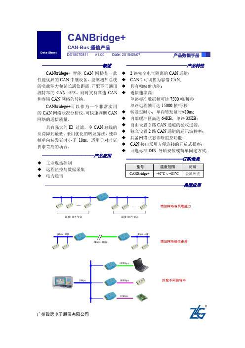
——————————————概述CANbridege+ 智能CAN 网桥是一款性能优异的CAN 中继设备,能够增加总线的负载能力和延长通信距离,匹配不同通讯波特率的CAN 网络,同时支持高速CAN 和容错CAN 网络的转换。
CANbridege+可以作为一个非常实用的CAN 网络状况分析仪,可快速判断CAN 网络的通信质量。
具有强大的ID 过滤,令CAN 总线的负荷降到最低。
采用优化的转发算法,使单帧单向转发延时小于10us ,适用于对时延要求苛刻的场合。
——————————————产品特性◆ 2路完全电气隔离的CAN 通道; ◆ CAN 2可切换为容错CAN ; ◆ 具有帧映射功能; ◆通信速率高:单路标准数据帧可达7500帧/每秒 单路远程帧可达15000帧/每秒 ◆转发延时小:单向转发延时<10us; ◆ 内部缓冲区高达64KB ,单路32KB ; ◆自由设置2路CAN 通道的验收过滤; ◆独立设置2路CAN 通道的通讯波特率; ◆具备网络状态诊断监控功能;◆CAN 接口采用方便连接的开放式插座; CANBridge+CAN-Bus 通信产品广州致远电子股份有限公司修订历史目录1. 功能简介 (1)2. 技术指标 (2)3. 电气参数 (3)4. 引脚连接 (4)5. 出厂设置 (6)6. 操作方法 (7)6.1驱动安装 (7)6.2参数配置 (9)6.2.1基本设置 (10)6.2.2验收滤波设置 (12)6.3容错CAN功能 (15)7. 声明 (16)1. 功能简介CANbridege+ 智能CAN 网桥是一款性能优异的CAN中继设备,能够增加总线的负载能力和延长通信距离,匹配不同通讯波特率的CAN网络,同时支持高速CAN和容错CAN 网络的转换。
CANbridege+ 智能CAN 网桥采用32位ARM处理器,系统时钟高达120MHz;数据缓冲区高达64KB,保证了在高速大流量情况下不丢帧;采用优化的转发算法,使数据转发延时小,转发效率高。
郑州众智科技 SGCAN300 CAN 总线中继模块 用户手册说明书
SGCAN300CAN总线中继模块用户手册郑州众智科技股份有限公司SMARTGEN (ZHENGZHOU) TECHNOLOGY CO.,LTD.目次前言 (3)1 概述 (5)2 性能特点 (5)3 规格 (6)4 操作 (7)4.1 面板指示 (7)4.2 CAN1转光纤 (8)4.3 RS485转光纤 (8)4.4 CAN1转CAN2 (8)5 接线 (9)6 典型应用 (10)7 外形及安装尺寸 (11)8 故障排除 (12)前言是众智的中文商标是众智的英文商标SmartGen ― Smart的意思是灵巧的、智能的、聪明的,Gen是generator(发电机组)的缩写,两个单词合起来的意思是让发电机组变得更加智能、更加人性化、更好的为人类服务!不经过本公司的允许,本文档的任何部分不能被复制(包括图片及图标)。
本公司保留更改本文档内容的权利,而不通知用户。
地址:中国·河南省郑州高新技术开发区金梭路28号电话:+86-371-67988888/67981888/67992951+86-371-67981000(外贸)传真:+86-371-67992952邮箱:*****************网址: / 表1 版本发展历史日期版本内容2020-08-28 1.0 开始发布表2 本文档所用符号说明符号说明该图标提示或提醒操作员正确操作。
注意该图标表示错误的操作有可能损坏设备。
小心该图标表示错误的操作有可能会造成死亡、严重的人身伤害和重大的财产损失。
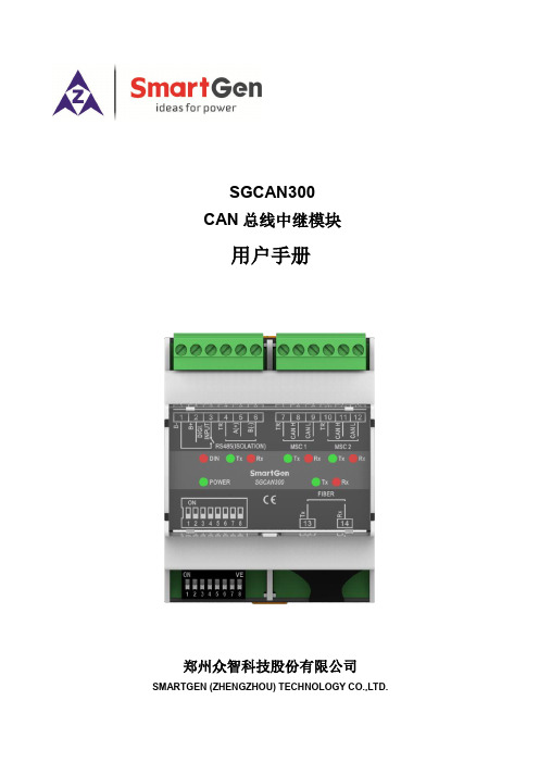
警告1 概述SGCAN300 CAN总线中继模块可实现MSC1信号与光纤信号的相互转换,MSC1信号与MSC2信号的相互转换,RS485信号与光纤信号的相互转换,使用该模块可增加MSC或RS485通信距离。
2 性能特点——具有MSC1与光纤转换功能,使用一对模块可实现远距离MSC通信;——具有RS485与光纤转换功能,使用一对模块可实现远距离RS485通信;——具有MSC1与MSC2数据转换功能,使用单个模块可增加MSC通信距离;——具有一个开关量输入口,可以控制信号转换功能的使能;——通过模块的拨码开关可以设置输入口的有效类型;——通过模块的拨码开关可以设置MSC1与MSC2的波特率;——通过模块的拨码开关可以设置RS485的波特率。
GENIUS总线光纤中继器用户手册
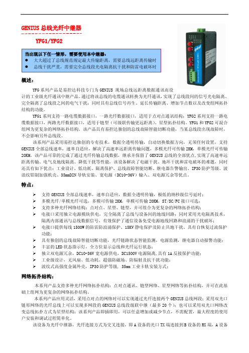
GENIUS 总线光纤中继器YFG1/YFG2概述:YFG 系列产品是易控达科技专门为GENIUS 现场总线远距离数据通讯而设计的工业级光纤通讯中继产品。
通过将该总线的电缆通讯转换为光纤通讯,实现了总线段间的信号光电隔离、完全隔离了总线段之间的电气干扰;同时具有总线信号再生、延长传输距离、增加节点数以及改变组网拓扑结构的功能。
YFG1系列支持一路电缆数据接口,一路光纤数据接口,适用于点对点通讯结构;YFG2系列支持一路电缆数据接口,两路光纤数据接口,适用于链型(可级联传输更远距离)、星型拓扑结构。
YFG1和YFG2可混合组网为更复杂的网络拓扑结构。
该产品具有易控达独创的总线故障智能切断功能,当某总线段出现故障时,不会影响另外总线段。
该系列产品采用易控达独创的专有技术,数据全透明传输,自动切换数据方向,无须任何设置,支持GENIUS 全部总线速率,速率自适应,解决了高速率远距离传输问题,多模光纤可传输2KM,单模光纤可传输20KM。
该产品可靠的完成了通过光纤传输总线数据,继承并保留了GENIUS 总线的全部优点,实现了高速率远距离传输、电气及地线隔离、降低干扰等性能,该设备解决了电磁干扰、地环干扰和雷电破坏的难题,同时还具有如下优点:工业设计、低功耗、隔离保护、总线故障智能切断、继电器告警输出、IP30防护等级、波浪纹铝制加强机壳、35mmDIN 导轨安装、宽电源(DC10-36V)输入、双电源冗余等优点。
特点:Ø支持GENIUS 全部总线速率,速率自适应,数据全透明传输,极低的纳秒级信号延时;Ø多模光纤/单模光纤可选,多模可传输2KM,单模可传输20KM,ST/SC/FC 接口可选;Ø支持多种光纤网络结构:点对点、星型、链型,并可组合为更复杂的网络拓扑结构;Ø电接口采用独立电源模块供电,完全隔离了总线与设备间的地线回路;同时采用光电隔离技术,隔离内部通讯与总线数据信号,有效保护了通信设备免受电源地线回路和浪涌的干扰破坏;Ø电接口提供每线1500W 的防雷防浪涌保护、15KV 静电保护及防止共地干扰、具有自恢复过流保护功能;Ø具有独创的总线故障智能切断功能,光纤链路状态智能监测,电源监测,继电器自动报警功能;Ø丰富的LED 状态指示灯,全方位显示总线和光纤运行状态;Ø独立双电源冗余,DC10-36V 宽电源供电,DC1500V 电源隔离,具有1A 反接保护功能;Ø工业级设计,无风扇、低功耗、超强防磁场、防辐射及抗干扰功能;Ø波纹式高强度金属外壳,IP30防护等级,35mm 工业卡轨安装方式;网络拓扑结构:本系列产品支持多种光纤网络拓扑结构:点对点通讯、链型网络、星型网络等拓扑结构,并可在此基础上组网为更复杂的网络拓扑结构。
GE说明书(A4,8page)(校正)
计数・计时器GE 系列使用说明书非常感谢您购买(株)韩国韩荣电子有限公司的产品。
请确认产品是否相符,并按照以下事项使用。
----------------------------------------------------------(株)韩国韩荣电子有限公司的认证现状安全注意事项为正确使用本产品,请务必在使用前认真阅读安全注意事项。
注意事项里列明的有关安全方面的重要内容,请务必遵守。
安全注意事项区分为危险、警告、注意。
危 险输出/输入端子有触电的危险,切勿与身体及通电物接触。
警 告1. 本机器的故障或异常有造成重大事故的危险,请在外围安装相应的保护回路,以防发生事故。
2. 本机器未附带电源开关及保险丝,需在外围另外安装。
(保险丝额定:250V 0.5A )3. 为了防止本机器发生破损及故障,请务必以额定电源电压供电。
4. 为了防止触电及机器故障,在未完成所有配线之前,切勿投入电源。
5. 本机器非属防爆构造,切勿在有易燃性、爆发性气体的场所使用。
6. 切勿对本机器进行分解、加工、改线、修理,会有触电、异常动作、火灾的危险。
7. 为了防止发生触电、误动作、故障,安装、拆卸本机器时,请把电源关掉。
8. 未按照制造商所指定的方法使用,可能会受伤或造成财产损失。
9. 在通电中使用本机器时,因有触电的危险,请把本机器先安装到面板上后再使用。
注 意1. 使用说明书的内容可能会在未事先通报或预告的状况下变更。
2. 请确认是否与订购的式样一致。
3. 请确认产品的在运输过程中的破损与否及异常状态。
4. 切勿在有腐蚀性气体(特别是有害气体,氨等)、易燃性气体的场所使用。
5. 请避开会直接对产品引起震动或冲击的场所使用。
6. 请在无水、油、药品、蒸汽、灰尘、盐分、铁粉等(污染等级1或2)的场所使用。
7. 切勿用酒精、苯等有机溶剂擦拭本产品(请使用中性洗剂)。
8. 请避开磁场阻碍大或会产生静电、磁场干扰的场所。
环网profibus总线光纤中继器说明书
=1000
设置 PROFIBUS 总线速率为 3Mbps
=0111
设置 PROFIBUS 总线速率为 6M bps
=0110
设置 PROFIBUS 总线速率为 12M bps
未使用
3、总线电缆连接:
易易控控达达 让让连连接接更更简简单单
本设备有一个 9 针的 SUB-D 插孔连接器,带有可固定连接器的销扣,用于连接 PROFIBUS 双绞线,直接 用 PROFIBUS 总线的专用快速连接器插入,然后用螺母拧紧即可。SUB-D 连接器的管脚定义完全符合 PROFIBUS 标准的建议,其第 3 脚与第 8 脚是电口的数据信号线,其第 6 脚是一个输出的 5V 电源,可以为外部的匹配 终端电阻提供电源。
PROFIBUS BUS OPTICAL FIBER Terminal resistance Distributed I/O Unit PLC I/O 输入输出单元
YFPB1
YFPB2 #1
YFPB2
#2 1
YFPB1
#3 1
星型(Star)
易易控控达达 让让连连接接更更简简单单
网络拓扑结构:
本系列产品支持多种光纤网络拓扑结构:点对点通讯、链型网络、星型网络及冗余环网自愈保护等拓 扑结构,并可在此基础上组网为更复杂的网络拓扑结构
本系列产品应用灵活,采用点对点的网络时可以实现通过光纤连接两个 PROFIBUS 总线网段;采用双光 口链形网络的光纤总线上可以实现多网段的 PROFIBUS 总线段级联中继(最多 200 个);也可以采用双光口网 络改变总线拓扑方式为星型结构;同时,该系列产品可采用双光口实现双纤环网冗余功能,当某处光纤故障 时,系统会在 10ms 内重建网络链路,保障系统的正常通信,实现对总线信号传输的自愈保护功能,网络故 障排除后系统会自动恢复;该系列产品采用公司自行研发的专有环网协议 ykd-ring,本协议是参考快速生成 树协议的基础上采用硬件实现解环协议,不需任何设置,不需要根节点,快速完成网络的成环和解环功能, 该系列产品即插即用,可以任意增加或减少节点,不需配置,最大程度的使用户安装和调试过程简单化。
GCAN-202,Ethernet转CAN用户手册

GCAN-202工业级以太网-CAN转换器用户手册文档版本:V3.52 (2017/09/30)目录1. 功能简介 (4)1.1 功能概述 (4)1.2 性能特点 (4)1.3 典型应用 (5)2. 设备安装 (6)2.1 安装固定 (6)2.2软件安装 (6)2.3 与PC连接 (6)2.4 与CAN总线连接 (6)3. 设备使用 (7)3.1 与PC连接进行配置 (7)3.2 与以太网连接 (7)3.3 与CAN连接 (8)3.4 CAN总线终端电阻 (9)3.5 系统状态指示灯 (9)4. CANet Config软件使用 (11)4.1 恢复出厂设置 (11)4.2 GCAN-202连接 (11)4.3 配置通讯基本信息 (11)4.4 配置完成 (12)4.5 保存/加载配置文件 (12)4.6 升级CANet固件内核(此功能请在指导下使用) (12)5. CANet简易测试软件使用 (14)6. 网络调试助手使用方法 (15)6.1 调试前准备工作 (15)6.2 TCP Server模式通信测试 (16)6.3 TCP Client模式通信测试 (17)6.4 UDP模式通信测试 (18)6.5 CAN口状态的TCP通知数据格式说明 (19)7.GCAN-202在线修改波特率功能 (20)7.1 功能说明 (20)7.2 格式说明 (20)7.3 发送举例 (20)8. 二次开发 (21)9. 技术规格 (22)10. 常见问题 (23)附录A:CAN2.0B协议帧格式 (24)附录B:GCAN-202(CANet)数据流定义 (26)1. 功能简介1.1 功能概述广成科技GCAN-202(CANET-II)是集成2路CAN接口、1路以太网接口的高性能型CAN-bus总线通讯接口卡。
采用GCAN-202高性能CAN接口卡,用户可以轻松完成CAN-bus 网络和以太网网络的互连互通,进一步拓展CAN-bus 网络的范围。
格林威尔开通维护指导介绍模板(最终版)之欧阳法创编
2021.03.09一局端汇聚设备MSAP-E6300P1.1 设备简介E6300P整机如图所示,其采用19英寸(宽)4U(高)插卡式结构,最多可以插19张盘。
电源盘,主控盘,上联盘为固定槽位,12个槽位可混插各种业务接口盘。
前面板示意图:图1-1E6300P前面板示意图E6300P机框主体分为19个槽位,编号从左到右依次编为1到18。
其中7和7A 槽位插入GE上联盘。
□ 1~6号槽位是业务盘槽位,支持业务盘混插;□多块EC63板卡安装时,可提前联系工程师,由工程师根据情况确定槽位号□ 7和7A号槽位是千兆以太网上联盘,固定槽位;□ 8号槽位是主控盘,固定槽位;□ 9、10号槽位是上联盘,固定槽位;□ 11~16号槽位是业务盘槽位,支持2021.03.09 欧阳法创编2021.03.092021.03.09 欧阳法创编 业务盘混插;□ 17、18号槽位是电源盘,固定槽位。
□ E6300P 机框还包括风扇盘,在机框的顶部,每块盘有三个风扇,并且有相应的告警指示灯。
开关2开关1220V 电源1220V 电源2外时钟输入2告警输出告警输入保护地-48V 电源1外时钟输出2外时钟输出1外时钟输入1网管1网管2-48V 电源2图1-2E6300P 后面板示意图□E/U 网管1,E/D 网管2:以太网网管接口,连接设备网管时使用1.2电气安装1.2.1保护地线及电源安装在设备后面板的电源接口下标有直流端子说明,其含义如下: □ -48V 为-48V 输入端; □ GND 为电源地接线端; □ PGND 为电源保护地接线端。
1.2.1.1交流电源线的连接电源接口位于机箱后面板。
交流220V 电源接口使用标准的三端带开关保险丝的电源插座,可直接使用标准的220V 电源线。
□ AC220V 电源接口:直接使用附件中2021.03.09提供的三相交流电源线;□确认设备的电源开关置于OFF位置后,按标识连接220V;□电源开关:处于ON位置时为电源接通1.2.1.2直流电源线的连接□确认保护地已经正确连接到大地。
最新GE公司LightSpeed16探测器理论及操作指导ppt课件

GEMSC CT APPL. TiP
螺旋扫描定制
16x1.25 mm
球管旋转一周由24排探测器收集16个信号,每1个信号由中心每2排探测 器或两侧每1个探测器收集,可后重建层厚为1.25, 2.5, 3.75, 5.0, 7.5, 10mm。
0.625:1模式——床速:6.25mm/转 0.875:1模式——床速:8.75mm/转 1.35:1模式——床速:13.5mm/转 1.675:1模式——床速:16.75mm/转
GEMSC CT APPL. TiP
螺旋扫描定制
8 x 2.5 mm
球管旋转一周由24排探测器搜集8个信号,中心每4排探测器收集1 个信号,两侧每2个探测器收集1个信号,图像后重建层厚为2.5, 3.75, 5.0, 7.5, 10mm。
准直器
Diode
FET Switching Array
GEMSC CT APPL. TiP
探测器结构
2 x 0.625mm
球管的焦点
准直器
球管旋转一周由2排探测 器收集2个信号。故最薄 层厚:0.625 mm
Diode
FET Switching Array
GEMSC CT APPL. TiP
轴位扫描模式
GEMSC CT APPL. TiP
轴位扫描的层间隔
层间隔=机架旋转一周的图像数目x层厚
例如: • 8 x 1.25 模式:机架旋转1周生成1.25mm层厚图像8幅,覆盖
10mm范围,层间隔为10mm。
D10m使用说明书

D10m使用说明书承蒙购买Panaonic产品,深表感谢。
使用前,请仔细阅读本使用说明书,以最适当的方式正确使用。
此外,请妥善保管本使用说明书。
各部名称ON、OFF、<操作部的说明>MODE键ON键、OFF键、设定值UP键设定值DOWN键·设定项目的选择·设定内容的选择·设定内容的确定·教导模式时的设定(注1):RUN模式以外的设定中按MODE键2秒以上返回RUN模式。
安装<使用DIN导轨时>放大器的安装方法①将放大器后部嵌入35mm宽的DIN导轨上。
②将放大器后部嵌入35mm宽的DIN导轨上。
将放大器前部嵌入35mm宽的DIN导轨上。
放大器的拆卸方法①手拿放大器,将其向前推。
②提起放大器前端,即可拆卸。
(注1):如果没有向前推放大器就提起前端的话,安装部分后端的挂钩可能会折损,敬请注意。
<使用螺丝时>●使用螺丝进行安装时,请使用带垫圈的M3小螺丝,并将紧固扭矩设为0。
5N·m以下。
光纤的安装安装附件后,请将光纤插入放大器。
详细内容请参阅光纤附带的“使用说明书”。
①直至不能移动为止。
②(注1)③使光纤锁杆复位,直至不能移动为止。
(注1):光纤插入不彻底会导致检测距离变短,敬请注意。
耐弯曲光纤易弯曲,插入时请注意。
(注2):对于同轴反射型光纤(FD-G4、FD-FM2等),请将中心光纤(单芯)安装到投光部“P”,将外围光纤(多芯)安装到受光部“D”。
装反会导致检测性能下降,敬请注意。
2点、设定阈值的方法。
通常用此方法设定。
ON的输出动作设定会自动反映。
g1MODEggg12Ёg12200gg1MODEggOFFg12Ёg12g●仅教导无工件状态(入光量稳定状态)、设定阈值的方法。
方便有背景物体时的检测及微小物体的检测。
●在投光量可变模式下选择Auto(附带“显示)时,可自动设定为适当的光量。
设定方法请参阅“模式”。
g2OFF2ON催gMODEgg11ON2гON2gPROāg200g全自动教导时●在不停止装配线而移动工件的状态下,欲设定阈值时,通过全自动教导进行设定。
GE LED光引导器安装指南说明书

Installation Guide SIGN025 | GE2025-0587GEXNLG15, GERDXNLG15, GEPOXNLG15, GEYAXNLG15, GELGXNLG15, GEGLXNLG15, GEBLXNLG15Remove the protective film from the light guide.Mark the light guide at the required length, adding 0.5 in. (13mm) for every 16 in. (406mm) to account for shrinkage during the forming process. Cut the light guide to the required length using a hacksaw, chop saw (cross cut or veneer blade only), band saw, or other appropriate plastic cutting tool.Fill the entire light guide channel with the GEXNBA Silicone Bend-Aid(s) and press into place. Bend-Aid must be installed prior to heating and forming. The GEXNBA Silicone Bend-Aid is reusable.PreparationSilicone Bend-AidWARNING/AVERTISSEMENTThe light guide is made to use together with the light engine. Please ensure you read the installation guide and warnings of light engine before installing. / Le guide est conçu pour une utilisation de pair avec un module DEL Contour. S’assurer de lire les instructions d’installation et les avertissements avant de procéder à l’installation.This device complies with part 15 of the FCC Rules. Operation is subject to the following two conditions: (1) This device may not cause harmful interference, and (2) this device must accept any interference received, including interference that may cause undesired operation.Note: This equipment has been tested and found to comply with the limits for a Class A digital device, pursuant to part 15 of the FCC Rules. These limits are designed to provide reasonable protection against harmful interference when the equipment is operated in a commercial environment . This equipment generates, uses, and can radiate radio frequency energy and, if not installed and used in accordance with the instruction manual, may cause harmful interference to radio communications. Operation of this equipment in a residential area is likely to cause harmful interference in which case the user will be required to correct the interference at his own expense.This Class [A] RFLD complies w i t h the Canadian standard ICES-005. Ce DEFR de la classe [A] est conforme à la NMB-005 du Canada.1234 WARNING/AVERTISSEMENTDO NOT heat and form the light guide with the light engine installed. NE PAS chauffer le guide alors qu’il contient le module DEL Contour.Contour Light Guide Forming InstructionsInstallation Guide Tetra ®Contour Light Guide Forming InstructionsHeating and FormingGently bend to the desired angle. It is recommended to use a heat-deflecting shield to distribute the heat evenly. Avoid localized overheating that may result in distortion or damage (i.e. bubbling) of the light guide. For large bends, use either an industrial oven or heating blanket. For small bends, use a heat gun.position until completely cooled. See the chart above for minimum bend radius guidelines.Allow the light guide to cool by natural convection or lightly forced cool air (i.e. fan). Remove the Bend-Aids for reuse. In order to remove any minor surface flaws, perform a light sanding using 400 grit sandpaper. Flared or deformed ends can be trimmed. The light guide is now ready for light engine installation.NOTE: DO NOT remove the Bend-Aids until the light guide has completely cooled.NOTE: DO NOT subject heated light guide to freezing or quenching in water.soft and pliable. Bend the light guide over a printed pattern, routed template, or use free-forming. A clean flat insulated surface (wood or laminated countertop) will help to prevent twisting or bowing. See the chart above for minimum bend radius © 2023 Current Lighting Solutions, LLC. All rights reserved. Information and specifications subject to change without notice. All values are design or typical values when measured under laboratory conditions.Page 2 of 2(Rev 06/19/23)SIGN025 | GE2025-0587。
- 1、下载文档前请自行甄别文档内容的完整性,平台不提供额外的编辑、内容补充、找答案等附加服务。
- 2、"仅部分预览"的文档,不可在线预览部分如存在完整性等问题,可反馈申请退款(可完整预览的文档不适用该条件!)。
- 3、如文档侵犯您的权益,请联系客服反馈,我们会尽快为您处理(人工客服工作时间:9:00-18:30)。
技术参数
电接口 接口类型:5PIN 的接线端子 通信速率:153.6STD、153.6EXT、76.8K 、38.4Kbit/s,速率自适应 信号延时(电口):100ns 电接口提供每线 1500W 的防雷浪涌保护、15KV 静电保护及防止共地干扰、自恢复过流保护功能 终端电阻:本机不带终端电阻,请按需要外接 光纤接口:
易易控控达达 让让连连接接更更简简单单
Genius 总线光纤中继器
YFG1/YFG2 系列
概述:
YFG 系列产品是易控达专门为 GE Genius 总线远距离数据通讯而设计的工 业级光纤通讯中继产品。具有总线段光电隔离,信号再生,延长传输距离,增 加节点数等功能。
该系列产品采用易控达独创的专有技术,数据全透明传输,自动切换数据方向,无须任何设置。YFG1 系列支持一路电缆数据接口,一路光纤数据接口,适用于点对点通讯结构;YFG2 系列支持一路电缆数据接口, 两路光纤数据接口,适用于链型(可级联传输更远距离)、星型拓扑结构。YFG1 和 YFG2 可混合组网为更复杂 的网络拓扑结构。
标准类型:0 ~ 70 °C (32 ~ 158 °F) 宽温类型:-40 ~ 85 °C (-40 ~ 185 °F) 操作湿度:5 ~ 95% RH 存放温度: -40 ~ 85 °C (-40 ~ 185 °F) 机械特性: 外形尺寸:132mm×105mm×52mm 外壳:IP30 防护等级,铝制加强机壳 安装方式: 35mmDIN 导轨安装 净重:800g 安规测试: EMI:EN55022 1998, Class A EMS: EN61000-4-2 (ESD), Criteria B, Level 4 EN61000-4-3 (RS), Criteria A, Level 2 EN61000-4-4 (EFT), Criteria B, Level 4 EN61000-4-5 (Surge), Criteria B, Level 2 EN61000-4-6 (CS), Criteria B, Level 2 En61000-4-8 (PFMF), Criteria A, Level 3 Freefall:IEC 60068-2-32
应用范围:
电力、交通、能源、监控及工业控制等领域。
规格型号
产品编号 描述
YFG1 YFG2
工业级 GE Genius 总线光纤中继器,(支持点对点结构),一路电接口,一路光模块接 口,多模/单模光纤可选,ST/SC/FC 接口可选,标配多模光纤 ST 接口
工业级 GE Genius 总线光纤中继器,(支持点对点、链型、星型拓扑),一路电接口, 两路光模块接口,多模/单模光纤可选,ST/SC/FC 接口可选,标配多模光纤 ST 接口
-9
光线路误码率:<10 电源及保护: 工作电压:双电源冗余输入,DC10V-36V 值,典型值 DC24V 工作电流:典型值 100mA@24V 电压保护:提供 L1+/M/L2+ 反接保护 电流保护:1 A (信号短接保护) 继电器告警输出:电口故障和光纤链路故障故障告警输出,触点容量:DC30V/1A、AC120V@1A 工作环境: 操作温度:
Genius BUS OPTICAL FIBER Terminal resistance Distributed I/O Unit
YFG1
YFG1 #2 #3
YFG1 #5
YFG1 #4
链型(Line)
易易控控达达 让让连连接接更更简简单单
Genius BUS OPTICAL FIBER Terminal resistance Distributed I/O Unit
特点:
速率自适应,无须拨码开关设置速率 透明传输,极低的纳秒级信号延时 独创的总线端口状态适时监测、光纤链路状态适时监测、继电器自动报警功能 支持点对对点、链型、星型、以及混合型等拓扑结构 8 个 LED 状态指示灯,全方位显示总线和光纤运行状态 电接口提供每线 1500W 的防雷浪涌保护、15KV 静电保护及防止共地干扰、自恢复过流保护功能 独立双电源冗余,DC10-36V 宽电源供电,DC1500V 电源隔离,具有 1A 反接保护功能 超强防磁场、防辐射及抗干扰功能 铝制加强机壳,IP30 防护等级, 35mm 工业卡轨安装方式
星型(Star)
YFG1 #1
YFG2 #2
YFG2 #3
YFG1 #4
YFG2
YFG2 #1
YFG2 #2
YFG1 #3
Genius BUS OPTICAL FIBER Terminal resistance Distributed I/O Unit
YFG2 #4
YFG2 #5
YFG2 #6
YFG1 #7
典型应用:
该设备为光纤中继器,光纤连接方式为交叉连接,即 A 设备的光口 TX 端连接到 B 设备的 RX 端,A 设备 的 RX 端连接到 B 设备的 TX 端。连接方式有点对点型、链型和星型三种基本型,并可在基本型的基础上组合 为更复杂的网络拓扑结构。 点对点(Point to Point)
#1
易易控控达达 让让连连接接更更简简单单
光口类型:多模、单模可选(1 个、2 个光纤口可选) 光口连接器:ST、SC、FC 可选,标配 ST 光纤波长:多模 1310 nm,单模 1310 nm 传输光纤:多模 50/125 um、62.5/125 um、100/140um,单模 8.3/125 um、9/125um、10/125um 传输距离:多模 0—2Km,来自模 0—20Km,更远距离可选
