基本VTP配置
单元任务书07_配置VTP

单元任务书07_配置VTP♑任务目标:1、能够配置VTP2、能够查看VTP状态信息♑学习形式✧小组协作,共同完成♑英语词汇:♑实践任务:任务一;VTP基本配置需求描述:⏹VTP域名为test⏹交换机SW1为Server模式,SW2、SW3为Client模式,学习SW1的VLAN信息推荐步骤:1、在SW1配置VTP,mode为server模式SW1(config)# vtp mode server2、在SW2配置VTP,mode为client模式SW2(config)# vtp mode client3、在SW3配置VTP,mode为client模式SW3(config)# vtp mode client4、在SW1配置VLANSW1(config)# vlan 2SW1(config-vlan)#exitSW1(config)# vlan 3SW1(config-vlan)#exit5、配置SW1的管理IP地址SW1(config)#int vlan 1SW1(config-if)# ip add 192.168.1.1 255.255.255.0SW1(config-if)# no shut6、查看SW1、SW2、SW3VLAN信息SW1# show vtp status任务二:VTP同步实验环境⏹SW1为服务器模式,SW2为客户机模式⏹VTP的域名为benet,密码为test⏹在SW1上配置VLAN 2和VLAN 3实验拓扑需求描述:配置完成并且同步以后,更改SW1的VTP配置,查看SW2是否还能学到SW1上的VLAN。
通过更改VTP配置,查看哪些原因导致客户机模式的交换机无法学习到VLAN信息。
推荐步骤:1、按照实验要求配置交换机,使得SW2学习到SW1的VLAN信息SW1#vlan databaseSW1(vlan)#vtp domain benetSW1(vlan)#vtp serverSW1(vlan)#vtp password testSW1(vlan)#vlan 2SW1(vlan)#vlan 3SW1(vlan)#exitSW1(config)#int f0/0SW1(config-if)#sw mo trunkSW1(config-if)#exitSW2#vlan databaseSW2(vlan)#vtp domain benetSW2(vlan)#vtp clientSW2(vlan)#vtp password testSW2(vlan)#exitSW2(config)#int f0/0SW2(config-if)#sw mo trunkSW2(config-if)#exit2、更改SW1的VTP密码,然后在SW1上配置VLAN4,查看SW2是否能学到VLAN4;然后将SW1的密码改回原密码,再查看SW2是否能学到VLAN4的信息3、更改SW1的VTP域名,然后在SW1上配置VLAN5,查看SW2是否能学到VLAN5,然后将SW1的域名改回原域名,再查看SW2是否能学到VLAN5的信息4、更改SW2的VTP模式为透明模式,然后在SW1上配置VLAN6,查看SW2是否能学到VLAN6;然后将SW2改回原模式,再查看SW2是否能学到VLAN6的信息;5、更改SW1和SW2之间的链路模式为ACCESS,然后在SW1上配置VLAN7,查看SW2是否能学到VLAN7;然后将SW1和SW2之间的链路模式改回Trunk,再查看SW2是否能学到VLAN7的信息W3VLAN信息。
实验二十:VTP配置
实验二十:VTP配置VTP(VLAN Trunking Protocol)是一个用于传播和同步关于整个交换网络的VLAN信息的协议,工作在OSI参考模型的第二层。
VTP使我们在扩展交换网络规模时减少人工配置的工作量,并通过统一地管理交换网络中VLAN的增加、删除和名称变更,以维持整个网络VLAN配置的一致性,最大限度地减少可能带来问题的错配和配置不一致情况(如VLAN名称重复使用或错误的VLAN类型说明)。
VTP的三种模式:Server服务器模式、Client客户机模式、Transparent 透明模式。
1、Server 服务器模式:可以创建、更改和删除VLAN信息,并设置用于整个VTP域的其它配置参数。
Server交换机上设置的这些消息会通过中断线路依次传到相同域中的VTP客户机中,以同步相同域内多台交换机Vlan的配置。
2、Client客户机模式:不能创建、更改和删除VLAN,只能通过中继线路同步接收相同域内VTP server服务器发来的VLAN信息。
3、Transparent透明模式:当前交换机不参加VTP,该种模式主要是用作本地管理,它不与其它交换机共享VLAN信息,但仍可以将VTP通告转送到其它交换机。
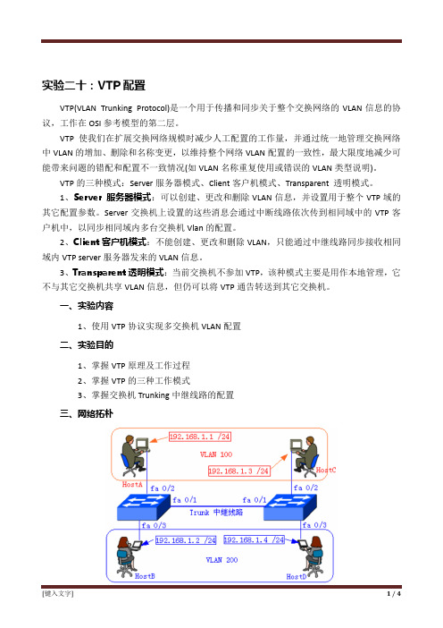
一、实验内容1、使用VTP协议实现多交换机VLAN配置二、实验目的1、掌握VTP原理及工作过程2、掌握VTP的三种工作模式3、掌握交换机Trunking中继线路的配置三、网络拓朴四、实验设备1、四台安装有windows 98/xp/2000的微机2、两台Cisco 2950 交换机3、多条直通网线和交叉网线4、思科(Cisco)专用控制端口连接电缆五、实验过程(需要将相关命令写入实验报告)1、使用直通线和交叉线将电脑与交换机、交换机与交换机正确进行连接2、配置各主机IP地址和子网掩码3、将交换机A设置为VTP Server服务器模式,同时设置VTP域名称并在该交换机上添加添加VLAN 100和VLAN 2004、将交换机B设置为VTP Client客户机模式。
VLAN TRUN VTP基本配置总结配置

VLAN(Virtual Local Area Network )中文解释虚拟局域网实现思想把同一物理局域网内的不同用户逻辑的划分成不同广播域定义一种将局域网设备从逻辑上划分成一个个网段,从而实现虚拟工作组的新兴数据交换技术作用 1.可有效的控制广播风暴的发生(提高网络性能)2.使网络拓扑图更加灵活3.控制网络中不同部门,不同站点间的互访(安全)VLAN标准IEEE802.1Q Cisco ISL标签(Cisco私有)VLAN添加命令一、Database配置方法switch>enableswitch#vlan database进入VLAN数据库配置模式switch(vlan)#vlan vlanID name vlan name创建VLAN并命名switch(vlan)#exi t 保存并退出配置实例switch>enable 进入特权模式switch#vlan database 进入VLAN数据库配置模式switch(vlan)#vlan 2 name er 创建VLAN2 名称erVLAN 2 added: 提示信息:VLAN2已经添加Name: er 提示信息:名称erswitch(vlan)#exit 退出并保存APPLY completed. 提示信息:保存成功Exiting.... 退出……二、全局配置方法Switch>enableSwitch#config terminalSwitch(config)#vlan vlanID输入vlanID,VLAN配置模式Switch(config)#nam vlanName输入VLAN名称(可选)Switch(config)#exit 退出VLAN删除命令no vlan vlanID一、 Database删除方法Switch>enable 进入特权模式Switch#vlan database 进入VLAN数据库配置模式Switch(vlan)#no vlan 2 删除VLAN 2Deleting VLAN 2... 提示信息:删除VLAN 2Switch(vlan)#exit 保存退出APPLY completed. 提示信息:完成Exiting.... 退出……二、 全局删除方法Switch>enableSwitch#configure terminalSwitch(config)# no vlan 2将端口添加到VLAN中Switch>enSwitch#conf tSwitch(config)#int f0/0 进入0/0接口Switch(config-if)#switchport mode access定义为二层端口模式Switch(config-if)#switchport access vlan 2将端口分配给VLAN 2Switch(config-if)#interface range f0/1 – 5 进入0/1 – 5接口Switch(config-if-range)#switchport mode accessSwitch(config-if-range)#switchport access vlan 3Switch(config-if-range)#end查看VLAN命令Switch#show vlan briefSwitch#show vlan id vlanIDSwitch#show vlan-switch briefSwitch#sh vlan-switch briefVLAN Name Status Ports---- -------------------------------- --------- ------------------------------- 1 default active Fa0/6, Fa0/7, Fa0/8, Fa0/9Fa0/10, Fa0/11, Fa0/12, Fa0/13 Fa0/14, Fa0/152 er active Fa0/0, Fa0/1, Fa0/2, Fa0/3Fa0/4, Fa0/53 san active4 si active1002 fddi-default active1003 token-ring-default active1004 fddinet-default active1005 trnet-default active配置实例SW>enSW#vlan daSW(vlan)#vlan 2 na erVLAN 2 modified:Name: erSW(vlan)#vlan 3 na sanVLAN 3 modified:Name: sanSW(vlan)#exitAPPLY completed.Exiting....SW#conf tEnter configuration commands, one per line. End with CNTL/Z. SW(config)#int f0/0SW(config-if)#swi mo accSW(config-if)#swi acc vlan 2SW(config-if)#int f0/15SW(config-if)#swi mo accSW(config-if)#swi acc vlan 3SW(config-if)#exitSW(config)#do sh vlan-s bVLAN Name Status Ports---- -------------------------------- --------- ------------------------------- 1 default active Fa0/1, Fa0/2, Fa0/3, Fa0/4Fa0/5, Fa0/6, Fa0/7, Fa0/8Fa0/9, Fa0/10, Fa0/11, Fa0/12Fa0/13, Fa0/142 er active Fa0/03 san active Fa0/151002 fddi-default active1003 token-ring-default active1004 fddinet-default active1005 trnet-default activeTRUNK (中继)中文解释:中继TRUNKING是基于OSI第二层数据链路层封转类型:ISL(Cisco私有协议,用于以太网的内部交换链路) IEEE 802.1Q(dot1q)作用:保证在跨越多个交换机上建立的同一个VLAN的成员能够相 互通信原理:交换机给每个去往其他交换机的数据帧打上VLAN标识 IEEE 802.1Q(dot1q) 工作原理和帧格式工作原理采用内部标记的方法标记的长度为4字节帧格式 Cisco ISL工作原理和帧格式工作原理 采用外部标记的方法标记的长度为30字节帧格式中继的集中模式配置命令Swithc>enableSwitch#configure terminalSwitch(config)#interface range f0/14 - 15SWITCH(config-if-range)#switchport mode ?access Set trunking mode to ACCESS unconditionally此模式为接入模式,用于连接PC的端口trunk Set trunking mode to TRUNK unconditionally此模式为TRUNK模式,用于交换机之间连接dynamic Set trunking mode to dynamically negotiateaccess or trunk mode此接口为动态协商模式Switch(config-if-range)#switchport mode trunk将接口设置为中继模式Switch(config-if-range)#switchport mode access将接口设置为接入模式配置实例SW1>enSW1#vlan da SW1(vlan)#vlan 2 na er VLAN 2 modified: Name: erSW1(vlan)#vlan 3 na san VLAN 3 modified: Name: san SW1(vlan)#exit APPLY completed. Exiting....SW1(config)#int ran f0/14 - 15 SW1(config-if-range)#swi mo tr SW1(config-if-range)#no sh SW1(config-if-range)#int f0/0 SW1(config-if)#swi mo ac SW1(config-if)#swi ac vlan 2 SW1(config-if)#no sh SW1(config-if)#int f0/1 SW1(config-if)#swiSW1(config-if)#swi mo ac SW1(config-if)#swi ac vlan 3 SW1(config-if)#no sh另一台交换机配置相同即可创建VLAN2和VLAN3将14-15接口配置为中继 将端口加入相应VLAN 中查看接口模式命令Switch#show interface interface-id switchport中文解释:VLAN中继协议(虚拟局域网干道协议)作用:它是一个OSI参考模型第二层的通信协议,主要用于管理在同一个域的网络范围内VLAN的建立、删除和重命名并自动地将信息向网络中其它的交换机广播优势:减少管理员负担和认为错误,提高安全性。
vtp
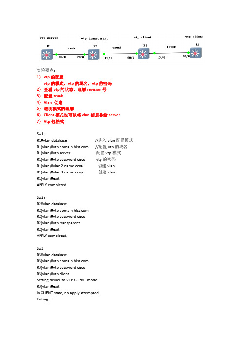
实验要点:1)vtp的配置vtp的模式,vtp的域名,vtp的密码2)查看vtp的状态,理解revision号3)配置trunk4)Vlan 创建5)透明模式的理解6)Client模式也可以将vlan信息传给server7)Vtp包格式Sw1:R1#vlan database //进入vlan配置模式R1(vlan)#vtp domain //配置vtp的域名R1(vlan)#vtp server 配置vtp模式R1(vlan)#vtp password cisco vtp的密码R1(vlan)#vlan 2 name ccna 创建vlanR1(vlan)#vlan 3 name ccnp 创建vlanR1(vlan)#exitAPPLY completedSw2:R2#vlan databaseR2(vlan)#vtp domain R2(vlan)#vtp password ciscoR2(vlan)#vtp transparentR2(vlan)#exitAPPLY completed.Sw3R3#vlan databaseR3(vlan)#vtp domain R3(vlan)#vtp password ciscoR3(vlan)#vtp clientSetting device to VTP CLIENT mode.R3(vlan)#exitIn CLIENT state, no apply attempted. Exiting....Sw4R4#vlan databaseR4(vlan)#vtp domain R4(vlan)#vtp password ciscoR4(vlan)#vtp clientR4(vlan)#exitIn CLIENT state, no apply attempted.Exiting....R1#show vtp statusVTP Version : 2Configuration Revision : 1Maximum VLANs supported locally : 256Number of existing VLANs : 7VTP Operating Mode : ServerVTP Domain Name : VTP Pruning Mode : DisabledVTP V2 Mode : DisabledVTP Traps Generation : DisabledMD5 digest : 0x9C 0xA3 0xDF 0x2B 0x8E 0xAA 0x40 0x31 Configuration last modified by 0.0.0.0 at 3-1-02 00:03:28Local updater ID is 0.0.0.0 (no valid interface found)R1#show vlan-switch briefVLAN Name Status Ports---- -------------------------------- --------- -------------------------------1 default active Fa0/0, Fa0/1, Fa0/2, Fa0/3Fa0/4, Fa0/5, Fa0/6, Fa0/7Fa0/8, Fa0/9, Fa0/10, Fa0/11Fa0/12, Fa0/13, Fa0/14, Fa0/152 ccna active3 ccnp active1002 fddi-default active1003 token-ring-default active1004 fddinet-default active1005 trnet-default activeR1#show int trunkR1#需要四个机器上面都要配置trunkRx(config)#int f0/0Rx(config-if)#switchport mode trunk默认封装的是802.1QR1#show int trunkPort Mode Encapsulation Status Native vlanFa0/0 on 802.1q trunking 1Port Vlans allowed on trunkFa0/0 1-1005Port Vlans allowed and active in management domainFa0/0 1-3Port Vlans in spanning tree forwarding state and not prunedFa0/0 1-3配置完毕trunk之后,需要在r1上增加或者删除一个vlan,触发vtp的更新通告(vtp通告,1是间隔性的,2是触发性的)R2#show vlan-switch briefVLAN Name Status Ports---- -------------------------------- --------- -------------------------------1 default active Fa0/2, Fa0/3, Fa0/4, Fa0/5Fa0/6, Fa0/7, Fa0/8, Fa0/9Fa0/10, Fa0/11, Fa0/12, Fa0/13Fa0/14, Fa0/151002 fddi-default active1003 token-ring-default active1004 fddinet-default active1005 trnet-default activeR2是透明,所以,不会同步vlan信息,但是会转发的R3#show vlan-switch briefVLAN Name Status Ports---- -------------------------------- --------- -------------------------------1 default active Fa0/2, Fa0/3, Fa0/4, Fa0/5Fa0/6, Fa0/7, Fa0/8, Fa0/9Fa0/10, Fa0/11, Fa0/12, Fa0/13Fa0/14, Fa0/152 ccna active3 ccnp active1002 fddi-default active1003 token-ring-default active1004 fddinet-default active1005 trnet-default activeR3#R4#show vlan-switch briefVLAN Name Status Ports---- -------------------------------- --------- -------------------------------1 default active Fa0/1, Fa0/2, Fa0/3, Fa0/4Fa0/5, Fa0/6, Fa0/7, Fa0/8Fa0/9, Fa0/10, Fa0/11, Fa0/12Fa0/13, Fa0/14, Fa0/152 ccna active3 ccnp active1002 fddi-default active1003 token-ring-default active1004 fddinet-default active1005 trnet-default activeR2是透明模式,可以单独的创建自己的vlanR2#vlan databaseR2(vlan)#vlan 100VLAN 100 added:Name: VLAN0100R2(vlan)#vlan 200VLAN 200 added:Name: VLAN0200R2(vlan)#exitAPPLY completed.Exiting....R2#show vlan-switch briefVLAN Name Status Ports---- -------------------------------- --------- -------------------------------1 default active Fa0/2, Fa0/3, Fa0/4, Fa0/5Fa0/6, Fa0/7, Fa0/8, Fa0/9Fa0/10, Fa0/11, Fa0/12, Fa0/13Fa0/14, Fa0/15100 VLAN0100 active200 VLAN0200 active1002 fddi-default active1003 token-ring-default active1004 fddinet-default active1005 trnet-default activeR2#透明模式的交换机不与vtp域中的其他机器交换vlan信息,但是可以对信息进行传递客户端模式的交换机会把vlan传给server模式的交换机吗?注意:误区很多人认为clinet不会把vlan信息传给server,认为只要把一个交换机的模式改成client模式,就可以放心了,认为这个交换机上的信息不会把它传给网络中的其他交换机实际上,client是可以传递vlan信息给server的,是要域名是一样的,只看revision号码,谁高,谁就可以把信息给对方。
VTP配置

VTP(VLAN Trunking Protocol)配置VTP domain:ccxx一.将各台交换机间链路设置中继S1(config)#int fa0/23S1(config-if)#switchport mode trunk%LINEPROTO-5-UPDOWN: Line protocol on Interface FastEthernet0/23, changed state to down %LINEPROTO-5-UPDOWN: Line protocol on Interface FastEthernet0/23, changed state to upS1(config-if)#exitS1(config)#S2(config)#interface range fastEthernet 0/23-24 选择多个端口S2(config-if-range)#switchport mode trunk 开启中继模式%LINEPROTO-5-UPDOWN: Line protocol on Interface FastEthernet0/24, changed state to down %LINEPROTO-5-UPDOWN: Line protocol on Interface FastEthernet0/24, changed state to upS2(config-if-range)#exitS2(config)#S3(config)#int f0/24S3(config-if)#switchport mode trunkS3(config-if)#exitS3(config)#二.设置三台交换机处于ccxx的VTP域,且密码为ciscoS1(config)#vtp domain ccxx 设置VTP域名为ccxx Changing VTP domain name from NULL to ccxxS1(config)#vtp password cisco 设置VTP密码为cisco Setting device VLAN database password to ciscoS1(config)#S2(config)#vtp domain ccxxDomain name already set to ccxx.S2(config)#vtp password ciscoSetting device VLAN database password to ciscoS2(config)#S3(config)#vtp domain ccxxDomain name already set to ccxx.S3(config)#vtp password ciscoPassword already set to ciscoS3(config)#三.设置S1为服务器模式,S2为透明模式,S3为客户端模式S1(config)#vtp mode server 设置S1为服务器模式Device mode already VTP SERVER.S1(config)#S2(config)#vtp mode transparent 设置S2为透明模式Setting device to VTP TRANSPARENT mode.S2(config)#S3(config)#vtp mode client 设置S3为客户模式Setting device to VTP CLIENT mode.S3(config)#四.在S1上创建人事部VLAN5和销售部VLAN10S1(config)#vlan 5S1(config-vlan)#name HRS1(config-vlan)#exitS1(config)#vlan 10S1(config-vlan)#name SalesS1(config-vlan)#exitS1(config)#五.查看S1的VLAN信息S1#show vlan briVLAN Name Status Ports---- -------------------------------- --------- -------------------------------1 default active Fa0/1, Fa0/2, Fa0/3, Fa0/4Fa0/5, Fa0/6, Fa0/7, Fa0/8Fa0/9, Fa0/10, Fa0/11, Fa0/12Fa0/13, Fa0/14, Fa0/15, Fa0/16Fa0/17, Fa0/18, Fa0/19, Fa0/20Fa0/21, Fa0/22, Fa0/245 HR active10 Sales active1002 fddi-default active1003 token-ring-default active1004 fddinet-default active1005 trnet-default active六.查看S2的VLAN信息S2#show vlan briVLAN Name Status Ports---- -------------------------------- --------- -------------------------------1 default active Fa0/1, Fa0/2, Fa0/3, Fa0/4Fa0/5, Fa0/6, Fa0/7, Fa0/8Fa0/9, Fa0/10, Fa0/11, Fa0/12Fa0/13, Fa0/14, Fa0/15, Fa0/16Fa0/17, Fa0/18, Fa0/19, Fa0/20Fa0/21, Fa0/221002 fddi-default active1003 token-ring-default active1004 fddinet-default active1005 trnet-default active由于S2是透明模式,所以不和其它域中交换机同步VLAN信息。
VTP配置

S5#config t
S5(config)#interface fa0/24
S5(config-if)#switchportmode trunk
3.在服务器上创建VLAN
S0#vlan database
S0(vlan)#vlan100nameT1
VLAN100added:
Name:T1
S1#config t
S1(config)#interface fa0/24
S1(config-if)#switchportmode trunk
(2)S2上的配置
S2#config t
S2(config)#interface fa0/24
S2(config-if)#switchportmode trunk
S2(config-if)#switchportaccessvlan100
S2(config-if)#interface fa0/2
S2(config-if)#switchportmodeaccess
S2(config-if)#switchportaccessvlan200
S2(config-if)#interface fБайду номын сангаас0/3
S1(config-if)#switchportmode access
S1(config-if)#switchportaccessvlan100
S1(config-if)#interface fa0/2
S1(config-if)#switchportmode access
S1(config-if)#switchportaccessvlan200
【步骤】
1.配置VTP
VTP配置
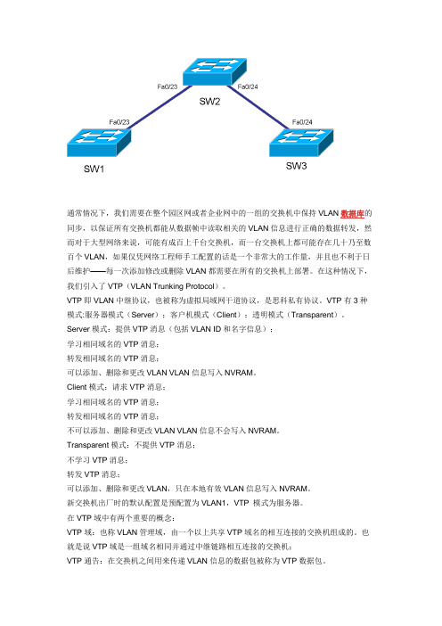
通常情况下,我们需要在整个园区网或者企业网中的一组的交换机中保持VLAN数据库的同步,以保证所有交换机都能从数据帧中读取相关的VLAN信息进行正确的数据转发,然而对于大型网络来说,可能有成百上千台交换机,而一台交换机上都可能存在几十乃至数百个VLAN,如果仅凭网络工程师手工配置的话是一个非常大的工作量,并且也不利于日后维护——每一次添加修改或删除VLAN都需要在所有的交换机上部署。
在这种情况下,我们引入了VTP(VLAN Trunking Protocol)。
VTP即VLAN中继协议,也被称为虚拟局域网干道协议,是思科私有协议。
VTP有3种模式:服务器模式(Server);客户机模式(Client);透明模式(Transparent)。
Server模式:提供VTP消息(包括VLAN ID和名字信息);学习相同域名的VTP消息;转发相同域名的VTP消息;可以添加、删除和更改VLAN VLAN信息写入NVRAM。
Client模式:请求VTP消息;学习相同域名的VTP消息;转发相同域名的VTP消息;不可以添加、删除和更改VLAN VLAN信息不会写入NVRAM。
Transparent模式:不提供VTP消息;不学习VTP消息;转发VTP消息;可以添加、删除和更改VLAN,只在本地有效VLAN信息写入NVRAM。
新交换机出厂时的默认配置是预配置为VLAN1,VTP 模式为服务器。
在VTP域中有两个重要的概念:VTP域:也称VLAN管理域,由一个以上共享VTP域名的相互连接的交换机组成的。
也就是说VTP域是一组域名相同并通过中继链路相互连接的交换机;VTP通告:在交换机之间用来传递VLAN信息的数据包被称为VTP数据包。
VTP通告包括:汇总通告,子集通告,通告请求。
注意:VTP通过Trunk,VTP Server向其它交换机传输信息和接收更新。
若给VTP配置密码,那么本域内的所有交换机的VTP密码必须保持一致。
VTP配置及VLAN间路由

桂林电子科技大学思科网络技术教程实验报告实验4 VTP配置及VLAN间路由第一部分基本VTP配置【实验目的:】1、执行基本交换机配置2、配置主机 PC 上的以太网接口3、在交换机上配置 VTP 和安全功能【实验预备知识】:复习理论课讲解的VTP相关知识和配置命令。
【实验拓扑图】:分析:配置VTP,首先确定结构,在结构中可以看到需要配置3个交换机其中确定并配置S2交换机是客户端,S3交换机是透明,S1是服务器和相同域,相同的管理接口。
所以S2和S3应该配置连接PC端的为接入模式分配不同的vlan和配置端口fa0/6、fa0/11 和fa0/18,使它们只支持一台主机,并且动态获知该主机的MAC 地址,交换机相连接口配置中继和本征,管理接口地址。
S1配置vlan【实验内容】:任务1:执行基本交换机配置根据以下原则配置交换机S1、S2 和S3 并保存配置:•按照拓扑所示配置交换机主机名。
•禁用DNS 查找。
•将执行模式口令配置为class。
•为控制台连接配置口令cisco。
•为vty 连接配置口令cisco。
任务 2:配置主机 PC 上的以太网接口使用地址表中的 IP 地址和默认网关配置PC1、PC2、PC3、PC4、PC5 和 PC6 的以太网接口。
任务 3:在交换机上配置 VTP 和安全功能步骤 1. 启用 S2 和 S3 上的用户端口。
将用户端口配置为接入模式。
请参阅拓扑图来确定哪些端口连接到最终用户设备。
S2(config)#interface fa0/6S2(config-if)#switchport mode accessS2(config-if)#no shutdownS2(config-if)#interface fa0/11S2(config-if)#switchport mode accessS2(config-if)#no shutdownS2(config-if)#interface fa0/18S2(config-if)#switchport mode accessS2(config-if)#no shutdown步骤 2. 用#show vtp status三台交换机上的当前 VTP 配置。
vtp配置知识点

VTP配置知识点VTP(VLAN Trunking Protocol)是用于在网络中自动传播VLAN信息的一种协议。
它可以帮助网络管理员更高效地管理VLAN,并确保所有网络设备都具有一致的VLAN信息。
在这篇文章中,我们将介绍VTP的配置知识点。
以下是一个逐步思考的过程,帮助我们理解和配置VTP。
第一步:了解VTP基本概念在开始配置VTP之前,我们需要了解一些基本概念。
VTP有三种模式:服务器模式(Server Mode)、客户端模式(Client Mode)和透明模式(Transparent Mode)。
服务器模式允许我们配置VLAN信息并传播给其他设备;客户端模式只能接收VLAN信息,不能进行配置;透明模式可以接收和传递VLAN信息,但不会更新自身的VLAN数据库。
第二步:配置VTP服务器首先,我们需要选择一个交换机作为VTP域的服务器。
我们可以通过以下命令进入全局配置模式:configure terminal然后,我们将交换机设置为服务器模式:vtp mode server接下来,我们为VTP域设置一个名称:vtp domain <域名称>我们还可以为VTP配置一个密码,以确保只有知道密码的设备才能加入VTP 域:vtp password <密码>最后,启用VTP功能:vtp enable第三步:配置VTP客户端如果我们有其他交换机需要加入VTP域,我们可以将它们配置为客户端模式。
首先,我们进入全局配置模式:configure terminal然后,将交换机设置为客户端模式:vtp mode client接下来,我们指定VTP域的名称和密码(如果有的话):vtp domain <域名称>vtp password <密码>最后,启用VTP功能:vtp enable第四步:配置VTP透明模式有时候,我们可能需要将某些交换机配置为透明模式,以便它们能够接收和传递VLAN信息,但不会更新自身的VLAN数据库。
基本VTP配置

基本VTP 配置任务1:执行基本交换机配置根据以下原则配置交换机S1、S2 和S3 并保存配置:????按照拓扑所示配置交换机主机名。
????禁用DNS 查找。
????将执行模式口令配置为class。
????为控制台连接配置口令cisco。
????为vty 连接配置口令cisco。
Switch>enableSwitch#configure terminalEnter configuration commands, one per line. End with CNTL/Z.Switch(config)#hostname S1S1(config)#enable secret classS1(config)#no ip domain-lookupS1(config)#line console 0S1(config-line)#password ciscoS1(config-line)#loginS1(config-line)#line vty 0 15S1(config-line)#password ciscoS1(config-line)#loginS1(config-line)#end%SYS-5-CONFIG_I: Configured from console by consoleS1#copy running-config startup-configDestination filename [startup-config]?Building configuration...[OK]任务2:配置主机PC 上的以太网接口使用地址表中的IP 地址和默认网关配置PC1、PC2、PC3、PC4、PC5 和PC6 的以太网接口。
任务3:在交换机上配置VTP 和安全功能步骤1. 启用S2 和S3 上的用户端口。
将用户端口配置为接入模式。
请参阅拓扑图来确定哪些端口连接到最终用户设备。
S2(config)#interface fa0/6S2(config-if)#switchport mode accessS2(config-if)#no shutdownS2(config-if)#interface fa0/11S2(config-if)#switchport mode accessS2(config-if)#no shutdownS2(config-if)#interface fa0/18S2(config-if)#switchport mode accessS2(config-if)#no shutdown步骤2. 检查三台交换机上的当前VTP 配置。
VTP实验

实验二:交换机VTP配置一、实验内容与要求:1、掌握交换剂VLAN的基本配置2、掌握VTP的基本配置二、设备需求安装了WindowsXP的计算机一台,Packet Tracer模拟器软件。
三、线缆连接及配置说明在模拟器软件中,设置如下图所示的拓扑结构交换机2交换机1交换机3四、实验步骤VTP的作用是流量在穿越整个网络的过程中维持vlan信息不变。
VTP是一种消息协议,通过使用2层中Frame 在整个网络中负责管理vlan的添加,删除和重命名。
通过一台工作在VTP 服务器模式下的中央交机完成这些任务。
VTP负责在vlan域内同步vlan信息,这样就不需要在每台交换机配置vlan信息了。
VTP 有3种模式Server 服务器模式缺省模式, 可建立、修改和删除 VLAN, 向同一域中的交换机通告它的 VLAN 配置,并接受从Trunk 链路上收到的通告与其它交换机进行VLAN 配置的同步。
VTP服务器还可以确定其他参数, 例如 VTP 版本号和整个 VTP 域中的 VTP 裁剪, VTP 信息放置在VRAM中。
Client 客户端模式行为同服务器模式, 但不能建立、改变或删除VLAN;倾听vlan信息, 使得自己的vlan 配置信息保持与VTP服务器同步;也可以把vlan信息转发给其它交换机。
Transparent 透明模式不参与 VTP。
在 VTP v2 中, 配置为透明模式的交换机将在 Trunk 端口上转发 VTP 信息以保证其他交换机接收到更新信息, 但这些交换机将不修改自己的数据库, 也不发送指示VLAN 状态发生变化的更新信息。
VTP v1中, 透明模式的交换机也不转发vtp信息到其它交换机。
需要注意的是透明模式下的交换机可以在本地创建 vlan, 但这些vlan的变化信息不会扩散到其它交换机。
(1)登陆交换机:单击PC-PT PC0图标,出现图1所示窗口,单击途中红色框选图标,进入图2所示的超级终端设置界面,保持其默认设置。
实验4.4.1 基本VTP配置

实验4.4.1 基本VTP配置任务1:布置网络步骤1:按拓扑图所示搭建一个类似的网络,建立到所有三台交换机的控制台连接。
步骤2:清除交换机的所有配置,使用show vlan 命令来确认只存在默认VLAN,并且所有端口都已分配给VLAN 1。
步骤3:使用shutdown 命令禁用所有端口。
任务2:执行基本的交换机配置步骤1:完成交换机S1、S2 和S3 的基本配置。
步骤2:启用S2 和S3 上的用户端口,将用户端口配置为接入模式。
步骤3:重新启用S1、S2 和S3 上的中继端口。
任务3:在主机PC 上配置以太网接口使用本实验开头部分地址表中的IP 地址和默认网关配置PC1、PC2、PC3、PC4、PC5 和PC6 的以太网接口。
任务4:在交换机上配置VTP步骤1:检查三台交换机上的当前VTP 设置。
步骤2:在所有三台交换机上配置工作模式、域名和VTP 口令。
在三台交换机上,全部将VTP 域名设置为Lab4,VTP 口令设置为cisco。
将S1 配置为服务器模式,S2 配置为客户端模式,S3 配置为透明模式。
步骤3:为所有三台交换机上的中继端口配置中继和本征VLAN。
在全局配置模式下使用interface-range 命令来简化此项任务。
步骤4:在S2 和S3 接入层交换机上配置端口安全功能。
配置端口fa0/6、fa0/11 和fa0/18,使它们只支持一台主机,并且动态获知该主机的MAC 地址。
步骤5:在VTP 服务器上配置VLAN。
步骤6:检查S1 上创建的VLAN 是否已分发给S2 和S3。
在S2 和S3 上使用show vlan brief 命令检查VTP 服务器是否已将其VLAN 配置传送给所有的交换机。
所有交换机上配置的VLAN 都相同吗?______不同_________ 。
解释为什么S2 和S3 具有不同的VLAN 配置。
__因为S3是透明模式,透明模式的交换机不通告自身的VLAN配置,也不与其他交换机同步VLAN配置____。
实验 4.4.1:基本 VTP 配置
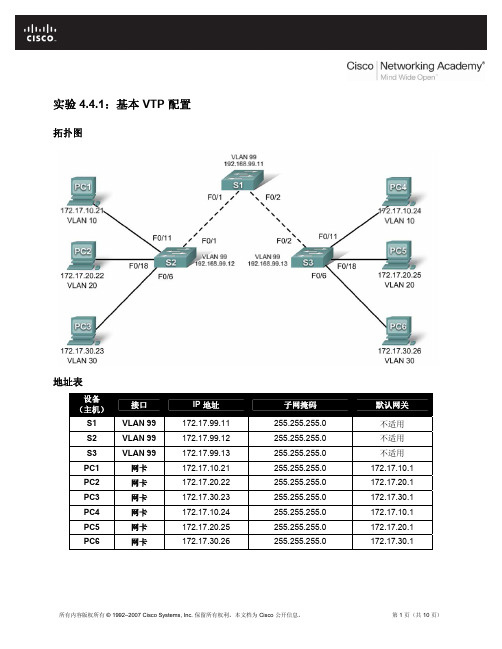
实验 4.4.1:基本 VTP 配置拓扑图地址表设备(主机)名接口 IP 地址 子网掩码 默认网关S1 VLAN 99 172.17.99.11 255.255.255.0 不适用 S2 VLAN 99 172.17.99.12 255.255.255.0 不适用 S3 VLAN 99 172.17.99.13 255.255.255.0 不适用PC1 网卡 172.17.10.21 255.255.255.0 172.17.10.1 PC2 网卡 172.17.20.22 255.255.255.0 172.17.20.1 PC3 网卡 172.17.30.23 255.255.255.0 172.17.30.1 PC4 网卡 172.17.10.24 255.255.255.0 172.17.10.1 PC5 网卡 172.17.20.25 255.255.255.0 172.17.20.1 PC6网卡172.17.30.26 255.255.255.0 172.17.30.1端口分配(交换机 2 和 3)端口分配网络Fa0/1 – 0/5 802.1q 中继(本征 VLAN 99)172.17.99.0 /24Fa0/6 – 0/10 VLAN 30 – Guest (Default) 172.17.30.0 /24Fa0/11 – 0/17 VLAN 10 – Faculty/Staff 172.17.10.0 /24Fa0/18 – 0/24 VLAN 20 – Students 172.17.20.0 /24学习目标完成本实验后,您将能够:•根据拓扑图进行网络布线•删除交换机启动配置并将交换机重新加载到默认状态•执行交换机上的基本配置任务•在所有交换机上配置 VLAN 中继协议 (VTP)•对交换机间连接启用中继•检验中继配置•修改 VTP 模式并观察产生的影响•在 VTP 服务器上创建 VLAN,并将此 VLAN 信息分发给网络中的交换机•说明 VTP 透明模式、服务器模式和客户端模式之间的工作差异•为 VLAN 分配交换机端口•保存 VLAN 配置•在网络上启用 VTP 修剪功能•说明修剪功能如何减少 LAN 中不必要的广播流量任务 1:准备网络步骤 1:根据拓扑图所示完成网络电缆连接。
实验四 配置VTP

实验四配置VTP(VLAN中继协议)一、VTP的配置实验拓扑图【准备知识】1、VTP实现单点访问控制VLAN信息的作用。
是CISCO的私有协议。
2、VTP工作在OSI参考模型第二层,组播地址:01-00-0c-cc-cc-cc。
3、 VTP使用条件:交换机直连、同域(domain),同密(Password),拥有中继端口(trunk)。
4、VTP模式:VTP Server :交换机默认为Server模式,在域中至少有一台交换机处于此模式。
Client、Transparent 此模式在VTP 不同版本表现是不同的。
5、VTP消息类型:每300秒发送一次,当网络拓扑发生变化时也会发送。
汇总通告:包含目前的VTP域名与配置修改编号。
配置修改编号的范围(0~232 - 1)。
子集通告:包含VLAN配置的详细信息。
通告请求:发送前提为,a、交换机重起后 b、VTP域名发生变化后 c、交换机接受到修改配置编号比自己高的汇总通告。
6、交换机修改配置编号重设为0的方法:a、更改交换机的域名b、将交换机的模式该为透明模式后再该为其他的模式。
【实验步骤】1、先在三层交换机3560上配置如下:Switch#vlan databaseSwitch(vlan)#vtp domain senya //配置VTP域名,默认为空Switch(vlan)#vtp server //设置交换机为Server模式,实际上这是默认值Switch(config-if)#int fa0/1Switch(config-if)#switchport mode trunk //配置端口fa0/1为trunk模式Switch(config-if)#int fa0/2Switch(config-if)#switchport mode trunk //配置端口fa0/2为trunk模式Switch(vlan)#vlan 2 //创建VLAN2Switch(vlan)#vlan 3 //创建VLAN3Switch#conf tSwitch(config)#int vlan 2 //创建SVI 2Switch(config-if)#ip add 192.168.1.1 255.255.255.0 //配置VLAN 2的网关地址Switch(config-if)#no shutdownSwitch(config-if)#int vlan 3Switch(config-if)#ip add 192.168.2.1 255.255.255.0Switch(config-if)#no shutdown2、交换机S1上的配置:Switch>enSwitch#vlan databaseSwitch(vlan)#vtp domain senya //配置VTP域名Switch(vlan)#vtp client //设置交换机为Client模式Switch(vlan)#exitSwitch#conf tSwitch(config)#int fa0/3Switch(config-if)#switchport mode trunk //配置端口fa0/3为trunk模式Switch(config-if)#exitSwitch(config)#int fa0/1Switch(config-if)#switchport access vlan 2 //将端口fa0/1划到VLAN 2中Switch(config-if)#exitSwitch(config)#int fa0/2Switch(config-if)#switchport access vlan 3 //将端口fa0/2划到VLAN 3中3、交换机S2上的配置:Switch>enSwitch#vlan databaseSwitch(vlan)#vtp domain senyaSwitch(vlan)#vtp clientSwitch(vlan)#exitSwitch#conf tSwitch(config)#int fa0/1Switch(config-if)#sw ac vlan 2Switch(config-if)#exitSwitch(config)#int f0/2Switch(config-if)#sw ac vlan 3Switch(config-if)#exitSwitch(config)#int fa0/3Switch(config-if)#switchport mode trunk二、VTP修剪的配置Vtp 修剪可减少不必要的广播。
PT 练习 4.4.1:基本 VTP 配置(教师版)
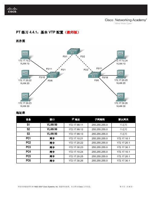
PT 练习 4.4.1:基本 VTP 配置(教师版)拓扑图地址表设备接口IP 地址子网掩码默认网关S1 VLAN 99 172.17.99.11 255.255.255.0 不适用S2 VLAN 99 172.17.99.12 255.255.255.0 不适用S3 VLAN 99 172.17.99.13 255.255.255.0 不适用PC1 网卡172.17.10.21 255.255.255.0 172.17.10.1 PC2 网卡172.17.20.22 255.255.255.0 172.17.20.1 PC3 网卡172.17.30.23 255.255.255.0 172.17.30.1 PC4 网卡172.17.10.24 255.255.255.0 172.17.10.1 PC5 网卡172.17.20.25 255.255.255.0 172.17.20.1 PC6 网卡172.17.30.26 255.255.255.0 172.17.30.1端口分配(S2 和 S3)学习目标•执行基本交换机配置•配置主机PC 上的以太网接口•在交换机上配置VTP 和安全功能简介在本练习中,您的任务包括:执行基本的交换机配置、配置 VTP 和中继、了解 VTP 模式、创建和分发VLAN 信息以及将端口分配给 VLAN。
本练习开始时,网络处于安全状态,所有端口都已管理性关闭。
任务 1:执行基本交换机配置根据以下原则配置交换机S1、S2 和 S3 并保存配置:•按照拓扑所示配置交换机主机名。
•禁用DNS查找。
•将执行模式口令配置为class。
•为控制台连接配置口令cisco。
•为vty 连接配置口令cisco。
Switch>enableSwitch#configure terminalEnter configuration commands, one per line. End with CNTL/Z.Switch(config)#hostname S1S1(config)#enable secret classS1(config)#no ip domain-lookupS1(config)#line console 0S1(config-line)#password ciscoS1(config-line)#loginS1(config-line)#line vty 0 15S1(config-line)#password ciscoS1(config-line)#loginS1(config-line)#end%SYS-5-CONFIG_I: Configured from console by consoleS1#copy running-config startup-configDestination filename [startup-config]?Building configuration...[OK]任务 2:配置主机 PC 上的以太网接口使用地址表中的 IP 地址和默认网关配置PC1、PC2、PC3、PC4、PC5 和 PC6 的以太网接口。
VTP(VLAN Trunk Protocol)配置

动态NAT配置(2009-03-27 19:57:50)标签:动态nat杂谈分类:Cisco交换路由实验一、R1配置:Router>enableRouter#configure terminalEnter configuration commands, one per line. End with CNTL/Z.Router(config)#hostname R1R1(config)#R1(config)#end%SYS-5-CONFIG_I: Configured from console by consoleR1#copy running-config startup-configDestination filename [startup-config]?Building configuration...[OK]R1#configure tEnter configuration commands, one per line. End with CNTL/Z.R1(config)#interface fastEthernet 0/0R1(config-if)#ip address 192.168.1.254 255.255.255.0R1(config-if)#no shutdown%LINK-5-CHANGED: Interface FastEthernet0/0, changed state to up%LINEPROTO-5-UPDOWN: Line protocol on Interface FastEthernet0/0, changed state toupR1(config-if)#exitR1(config)#interface serial 2/0R1(config-if)#ip address 202.96.1.1 255.255.255.0R1(config-if)#clock rate 64000R1(config-if)#no shutdownR1(config)#router ripR1(config-router)#version 2R1(config-router)#no auto-summaryR1(config-router)#network 202.96.1.0R1(config)#ip nat pool TIANXUAN 202.96.1.3 202.96.1.100 netmask 255.255.255.0 R1(config)#access-list 1 permit 192.168.1.0 0.0.0.255R1(config)#ip nat inside source list 1 pool TIANXUANR1(config)#interface fastEthernet 0/0R1(config-if)#ip nat insideR1(config-if)#exitR1(config)#interface serial 2/0R1(config-if)#ip nat outsideR1(config-if)#exitR1(config)#^Z%SYS-5-CONFIG_I: Configured from console by consoleR1#show ip routeCodes: C - connected, S - static, I - IGRP, R - RIP, M - mobile, B - BGPD - EIGRP, EX - EIGRP external, O - OSPF, IA - OSPF inter areaN1 - OSPF NSSA external type 1, N2 - OSPF NSSA external type 2E1 - OSPF external type 1, E2 - OSPF external type 2, E - EGPi - IS-IS, L1 - IS-IS level-1, L2 - IS-IS level-2, ia - IS-IS inter area * - candidate default, U - per-user static route, o - ODRP - periodic downloaded static routeGateway of last resort is not set2.0.0.0/24 is subnetted, 1 subnetsR 2.2.2.0 [120/1] via 202.96.1.2, 00:00:15, Serial2/0C 192.168.1.0/24 is directly connected, FastEthernet0/0C 202.96.1.0/24 is directly connected, Serial2/0R1#show ip nat statisticsTotal translations: 2 (0 static, 2 dynamic, 0 extended)Outside Interfaces: Serial2/0Inside Interfaces: FastEthernet0/0Hits: 22 Misses: 2Expired translations: 0Dynamic mappings:-- Inside Sourceaccess-list 1 pool TIANXUAN refCount 2pool TIANXUAN: netmask 255.255.255.0start 202.96.1.3 end 202.96.1.100type generic, total addresses 98 , allocated 2 (2%), misses 0R1#show ip nat translationsPro Inside global Inside local Outside local Outside global --- 202.96.1.3 192.168.1.1 --- ------ 202.96.1.4 192.168.1.2 --- ------ 202.96.1.5 192.168.1.3 --- ------ 202.96.1.6 192.168.1.4 --- ---R1#debug ip natIP NAT debugging is onR1#debug ip natIP NAT debugging is onR1#NAT: s=192.168.1.1->202.96.1.6, d=2.2.2.2[5]NAT*: s=2.2.2.2, d=202.96.1.6->192.168.1.1[5]NAT: s=192.168.1.1->202.96.1.6, d=2.2.2.2[5]NAT*: s=2.2.2.2, d=202.96.1.6->192.168.1.1[5]NAT: s=192.168.1.1->202.96.1.6, d=2.2.2.2[5]NAT*: s=2.2.2.2, d=202.96.1.6->192.168.1.1[5]NAT: s=192.168.1.1->202.96.1.6, d=2.2.2.2[5]NAT*: s=2.2.2.2, d=202.96.1.6->192.168.1.1[5]R1#NAT: s=192.168.1.1->202.96.1.6, d=2.2.2.2[5]NAT*: s=2.2.2.2, d=202.96.1.6->192.168.1.1[5]NAT: s=192.168.1.1->202.96.1.6, d=2.2.2.2[5]NAT*: s=2.2.2.2, d=202.96.1.6->192.168.1.1[5]NAT: s=192.168.1.1->202.96.1.6, d=2.2.2.2[5]NAT*: s=2.2.2.2, d=202.96.1.6->192.168.1.1[5]NAT: s=192.168.1.1->202.96.1.6, d=2.2.2.2[5]NAT*: s=2.2.2.2, d=202.96.1.6->192.168.1.1[5]NAT: s=192.168.1.1->202.96.1.6, d=2.2.2.2[5]NAT*: s=2.2.2.2, d=202.96.1.6->192.168.1.1[5]NAT: s=192.168.1.1->202.96.1.6, d=2.2.2.2[5]NAT*: s=2.2.2.2, d=202.96.1.6->192.168.1.1[5]NAT: s=192.168.1.1->202.96.1.6, d=2.2.2.2[5]NAT*: s=2.2.2.2, d=202.96.1.6->192.168.1.1[5]二、R2配置:Router>enableRouter#configure terminalEnter configuration commands, one per line. End with CNTL/Z. Router(config)#hostname R2R2(config)#R2(config)#end%SYS-5-CONFIG_I: Configured from console by consoleR2#copy running-config startup-configDestination filename [startup-config]?Building configuration...[OK]R2(config)#interface serial 3/0R2(config-if)#ip address 202.96.1.2 255.255.255.0R2(config-if)#no shutdownR2(config)#interface loopback 0R2(config-if)#ip address 2.2.2.2 255.255.255.0R2(config)#router ripR2(config-router)#version 2R2(config-router)#no auto-summaryR2(config-router)#network 2.0.0.0R2(config-router)#network 202.96.1.0R2#ping 2.2.2.2Type escape sequence to abort.Sending 5, 100-byte ICMP Echos to 2.2.2.2, timeout is 2 seconds:!!!!!Success rate is 100 percent (5/5), round-trip min/avg/max = 16/16/16 msR2#ping 202.96.1.1Type escape sequence to abort.Sending 5, 100-byte ICMP Echos to 202.96.1.1, timeout is 2 seconds:!!!!!Success rate is 100 percent (5/5), round-trip min/avg/max = 31/31/32 msR2#ping 192.168.1.1Type escape sequence to abort.Sending 5, 100-byte ICMP Echos to 192.168.1.1, timeout is 2 seconds: .....Success rate is 0 percent (0/5)三、小结核心:R1(config)#ip nat pool TIANXUAN 202.96.1.3 202.96.1.100 netmask 255.255.255.0 R1(config)#access-list 1 permit 192.168.1.0 0.0.0.255R1(config)#ip nat inside source list 1 pool TIANXUANR1(config)#interface fastEthernet 0/0 R1(config-if)#ip nat insideR1(config-if)#exitR1(config)#interface serial 2/0R1(config-if)#ip nat outsideR1(config-if)#exit动态地址池的IP地址应为合法地址,可能实际中不可能申请了这么多的IP地址。
实验3 VTP 配置

实验3 VTP 配置VTP(VLAN Trunk Protocol)提供了一种用于在交换机上管理VLAN 的方法,该协议使得我们可以在一个或者几个中央点(Server)上创建、修改、删除VLAN,VLAN 信息通过Trunk 链路自动扩散到其他交换机。
VTP 被组织成管理域(VTP Domain),相同域中的交换机能共享VLAN 信息。
根据交换机在VTP 域中的作用不同,VTP 可以分为三种模式:(1)服务器模式(Server):在VTP 服务器上能创建、修改、删除VLAN,同时这些信息会通告给域中的其他交换机。
默认情况下,交换机是服务器模式。
每个VTP 域必须至少有一台服务器,域中的VTP 服务器可以有多台。
(2)客户机模式(Client):VTP 客户机上不允许创建、修改、删除VLAN,但它会监听来自其他交换机的VTP 通告并更改自己的VLAN 信息。
接收到的VTP 信息也会在Trunk 链路上向其他交换机转发,因此这种交换机还能充当VTP 中继。
(3)透明模式(Transparent):这种模式的交换机不参与VTP。
可以在这种模式的交换机上创建、修改、删除VLAN,但是这些VLAN 信息并不会通告给其他交换机,它也不接受其他交换机的VTP 通告而更新自己的VLAN 信息。
然而需要注意的是,它会通过Trunk 链路转发接收到的VTP 通告从而充当了VTP 中继的角色,因此完全可以把该交换机看成是透明的。
VTP 通告是以组播帧的方式发送的,VTP 通告中有一个字段称为修订号(Revision),初始值为0。
只要在VTP Server 上创建、修改、删除VLAN,通告的Revision 就增加1,通告中还包含了VLAN 的变化信息。
需要注意的是:高Revision 的通告会覆盖低Revision 的通告,而不管谁是Server 还是Client。
交换机只接受比本地保存的Resivison 号更高的通告;如果交换机收到Resivison 号更低的通告,会用自己的VLAN 信息反向覆盖。
- 1、下载文档前请自行甄别文档内容的完整性,平台不提供额外的编辑、内容补充、找答案等附加服务。
- 2、"仅部分预览"的文档,不可在线预览部分如存在完整性等问题,可反馈申请退款(可完整预览的文档不适用该条件!)。
- 3、如文档侵犯您的权益,请联系客服反馈,我们会尽快为您处理(人工客服工作时间:9:00-18:30)。
基本VTP 配置任务1:执行基本交换机配置根据以下原则配置交换机S1、S2 和S3 并保存配置:按照拓扑所示配置交换机主机名。
禁用DNS 查找。
将执行模式口令配置为class。
为控制台连接配置口令cisco。
为vty 连接配置口令cisco。
Switch>enableSwitch#configure terminalEnter configuration commands, one per line. End with CNTL/Z.Switch(config)#hostname S1S1(config)#enable secret classS1(config)#no ip domain-lookupS1(config)#line console 0S1(config-line)#password ciscoS1(config-line)#loginS1(config-line)#line vty 0 15S1(config-line)#password ciscoS1(config-line)#loginS1(config-line)#end%SYS-5-CONFIG_I: Configured from console by consoleS1#copy running-config startup-configDestination filename [startup-config]?Building configuration...[OK]任务2:配置主机PC 上的以太网接口使用地址表中的IP 地址和默认网关配置PC1、PC2、PC3、PC4、PC5 和PC6 的以太网接口。
任务3:在交换机上配置VTP 和安全功能步骤1. 启用S2 和S3 上的用户端口。
将用户端口配置为接入模式。
请参阅拓扑图来确定哪些端口连接到最终用户设备。
S2(config)#interface fa0/6S2(config-if)#switchport mode accessS2(config-if)#no shutdownS2(config-if)#interface fa0/11S2(config-if)#switchport mode accessS2(config-if)#no shutdownS2(config-if)#interface fa0/18S2(config-if)#switchport mode accessS2(config-if)#no shutdown步骤2. 检查三台交换机上的当前VTP 配置。
使用show vtp status 命令确定所有三台交换机的VTP 工作模式。
步骤 3. 在所有三台交换机上配置工作模式、域名和VTP 口令。
在三台交换机上,全部将VTP 域名设置为Lab4,VTP 口令设置为cisco。
将S1 配置为服务器模式,S2配置为客户端模式,S3 配置为透明模式。
S1(config)#vtp mode serverDevice mode already VTP SERVER.S1(config)#vtp domain Lab4Changing VTP domain name from NULL to Lab4S1(config)#vtp password ciscoSetting device VLAN database password to ciscoS1(config)#endS2(config)#vtp mode clientSetting device to VTP CLIENT modeS2(config)#vtp domain Lab4Changing VTP domain name from NULL to Lab4S2(config)#vtp password ciscoSetting device VLAN database password to ciscoS2(config)#endS3(config)#vtp mode transparentSetting device to VTP TRANSPARENT mode.S3(config)#vtp domain Lab4Changing VTP domain name from NULL to Lab4S3(config)#vtp password ciscoSetting device VLAN database password to ciscoS3(config)#end步骤 4. 为所有三台交换机上的中继端口配置中继和本征VLAN。
在所有交换机上,为FastEthernet 接口0/1-5 配置中继和本征VLAN。
以下仅提供了每台交换机的fa0/1 接口的配置命令。
S1(config)#interface fa0/1S1(config-if)#switchport mode trunkS1(config-if)#switchport trunk native vlan 99S1(config-if)#no shutdownS1(config-if)#interface fa0/2S1(config-if)#switchport mode trunkS1(config-if)#switchport trunk native vlan 99S1(config-if)#no shutdownS1(config-if)#endS2(config)#interface fa0/1S2(config-if)#switchport mode trunkS2(config-if)#switchport trunk native vlan 99S2(config-if)#no shutdownS2(config-if)#endS3(config)#interface fa0/2S3(config-if)#switchport mode trunkS3(config-if)#switchport trunk native vlan 99S3(config-if)#no shutdownS3(config-if)#end步骤 5. 在S2 和S3 接入层交换机上配置端口安全功能。
配置端口fa0/6、fa0/11 和fa0/18,使它们只支持一台主机,并且动态获知该主机的MAC 地址。
S2(config)#interface fa0/6S2(config-if)#switchport port-securityS2(config-if)#switchport port-security maximum 1S2(config-if)#switchport port-security mac-address stickyS2(config-if)#interface fa0/11S2(config-if)#switchport port-securityS2(config-if)#switchport port-security maximum 1S2(config-if)#switchport port-security mac-address stickyS2(config-if)#interface fa0/18S2(config-if)#switchport port-securityS2(config-if)#switchport port-security maximum 1S2(config-if)#switchport port-security mac-address stickyS2(config-if)#endS3(config)#interface fa0/6S3(config-if)#switchport port-securityS3(config-if)#switchport port-security maximum 1S3(config-if)#switchport port-security mac-address stickyS3(config-if)#interface fa0/11S3(config-if)#switchport port-securityS3(config-if)#switchport port-security maximum 1S3(config-if)#switchport port-security mac-address stickyS3(config-if)#interface fa0/18S3(config-if)#switchport port-securityS3(config-if)#switchport port-security maximum 1S3(config-if)#switchport port-security mac-address stickyS3(config-if)#end步骤 6. 在VTP 服务器上配置VLAN。
本实验需要四个VLAN:VLAN 99 (management)VLAN 10 (faculty/staff)VLAN 20 (students)VLAN 30 (guest)在VTP 服务器上配置这些VLAN。
Packet Tracer 评分时会区分大小写。
S1(config)#vlan 99S1(config-vlan)#name managementS1(config-vlan)#exitS1(config)#vlan 10S1(config-vlan)#name faculty/staffS1(config-vlan)#exitS1(config)#vlan 20S1(config-vlan)#name studentsS1(config-vlan)#exitS1(config)#vlan 30S1(config-vlan)#name guestS1(config-vlan)#exit使用show vlan brief 命令检查S1 上是否创建了这些VLAN。
步骤7. 检查S1 上创建的VLAN 是否已分发给S2 和S3。
在S2 和S3 上使用show vlan brief 命令检查VTP 服务器是否已将其VLAN 配置传送给所有的交换机。
步骤8. 在S2 和S3 上创建新的VLAN。
S2(config)#vlan 88%VTP VLAN configuration not allowed when device is in CLIENT mode.S3(config)#vlan 88S3(config-vlan)#name testS3(config-vlan)#从S3 上删除VLAN 88。
