莱富康变频螺杆压缩机
莱富康压缩机应用手册1

SRC-XS 和 SRC-S 系列压缩机目录(SA-00-02-CH)SA0102CH 概要SA0204CH 冷冻油SA0303CH 制冷量调节SA0403CH 主要附件SA0506CH 电气装置SA0605CH 型号命名和技术参数SA0702CH 供货范围SA0803CH 外形尺寸和包装SA0902CH 性能参数SA1003CH 应用范围SA1103CH 外置油冷却SA1203CH 经济器SA1302CH 操作规程SA1402CH 维护保养SA1502CH 制冷量调节方式转换SA1600CH 故障分析SA9001CH 附录SRC-XS 和 SRC-S 系列压缩机概要(SA-01-02-CH)1.概要21.1 引言 21.2 压缩过程 31.3 转子 51.4 内置容积比 61.概要1.1 引言莱富康公司的SRC-S和SRC-XS系列压缩机(在图例1-A中给出了其主要结构部件装配图)是含油喷设计的双螺杆压缩机。
这款半封闭压缩机配有三相二极异步电动机(在50Hz时,转速为2900转/分)直接驱动阳转子,再带动阴转子转动。
压缩机配有高效油分离器,使得在安装制冷系统时无需配置任何外加部件。
电动机是通过特定的孔、槽由吸气来冷却。
对于SRC-S系列型号压缩机,制冷量调节是通过油压作用在油缸活塞带动滑阀来实现的。
活塞的位置决定了吸气腔容积的大小。
与此相反,对于134-XS系列型号,活塞的移动是由制冷剂气体旁通回压缩机吸气侧来实现的。
此两种系列的压缩机适用于制冷剂R22、R407C、R134a、R404A和R507的制冷系统。
紧凑型设计、低噪音、高效率、多机型和简便安装,使得此款压缩机能够满足主机制造厂商生产高效率和性能优良的水冷、风冷和热泵等机组。
1 转子;2 制冷量调节滑阀(仅用于SRC-S 系列);3 制冷量调节滑阀活塞(仅用于SRC-S 系列);4 排气截止阀;5 止回阀;6 油分离器(雾化器,SRC-XS 系列在侧部);7 集油/分油器;8 转子轴承;9 油加热器;10 油过滤器; 11 电动机; 12 吸气过滤器; 13 吸气截止阀; 14 电机保护装置; 15 接线盒; 17 吸气侧端盖; 18 转子组机壳; 19 轴承座(排气侧)。
水冷螺杆冷水机主要组成及其工作原理

水冷螺杆冷水机制冷系统的基本原理:液体制冷剂在蒸发器中吸收被冷却的物体热量之后,汽化成低温低压的蒸汽、被压缩机吸入、压缩成高压高温的蒸汽后排入冷凝器、在冷凝器中向冷却介质(水或者空气)放热,冷凝为高压液体、经节流阀节流为低压低温的制冷剂、再次进入蒸发器吸热汽化,达到循环制冷的目的。
这样,制冷剂在系统中经过蒸发、压缩、冷凝、节流四个基本过程完成一个制冷循环。
螺杆冷水机组主要由螺杆压缩机、冷凝器、蒸发器、膨胀阀及电控系统组成。
水冷螺杆单机头制冷原理如下图:水冷螺杆双机头制冷原理如下图:1.压缩机压缩机是整个空调系统的核心,也是系统动力的源泉。
整个空调的动力,全部由压缩机来提供,压缩机就相当于把一个实物由低势位搬到高势位地方去,在空调中它的目的就是把低温的气体通过压缩机压缩成高温的气体,最后气体在换热器中和其他的介质进行换热。
所以说压缩机的好坏会直接影响到整个空调的效果。
螺杆冷水机普通采用的是半封闭压缩机。
半封闭压缩机制冷量100~1200KW,结构紧凑,工作性能高,制冷能力大并可进行无级调节,但润滑油系统较复杂,躁声较高。
分为单,双螺杆型。
常见品牌:德BITZER 比泽尔﹑ GRASSO 格拉索,意大利FRASCOLD 富士豪﹑ REFCOMP 莱富康﹑ DORIN 多菱,日本 HITACHI 日立﹑ DAKIN 大金﹑ MITSUBISHI 三菱重工﹑KOBELCO 神钢﹑ MYCOM,韩国CENTURY,国外 FRICK,HOWDEN,台湾复盛﹑汉钟,中国重庆嘉陵﹑大连冰山等。
2.冷凝器冷凝器的作用是将压缩机排出的高温高压的制冷剂过热蒸汽冷却成液体或者气液混合物。
制冷剂在冷凝器种放出的热量由冷却介质(水或者空气)带走。
螺杆冷水机普通采用的是卧式壳管式水冷冷凝器。
冷凝器中制冷剂的热量被冷却水带走。
冷却水可以一次流过,也可以循环使用。
当循环使用时,需设置冷却塔或者冷却水池。
卧式壳管式冷凝器两端管板外面各用一个端盖封闭,端盖上铸有经过设计互相配合的分水筋,把整个管束分隔成几个管组。
压缩机技术资料

VLG螺杆系列产品VLGA/F系列螺杆压缩机组【产品特点】◎具有国际先进水平的第四代高效转子型线,采用双边非对称圆弧摆线齿型,采用先进的HOLROYD 专用转子磨床加工,可保证最精确的加工尺寸和最高的工作效率。
◎选用进口机械密封和滚动轴承,保证压缩机连续长期稳定运营。
◎机组内容积比可调,保证机组常年处在节能状态。
◎机组结构紧凑,布局合理,外型美观,运营可靠。
◎采用高效卧式油分离器,分离效果更加突出。
◎采用高效油冷却器,保证更高的换热效率。
◎机组设立了冷量自动调节装置,可以在10%~100%范围内实现制冷量的无级调节,达成了经济节能的目的。
◎高智能化电气控制,英国嘉德(GUARDIAN)国际控制公司集欧美多家制冷公司的优点,针对“大冷”机组特点开发的专用微电脑控制器。
运营速度更快、可靠性更高、控制功能更强,实现了模块化、网络化。
【工作合用范围】【重要技术参数】新系列螺杆压缩机组合用多种制冷剂,按压缩机转子直径(163、193、234、268、324、377)和滑阀导程(D、标准、T),共设有15个机型,理论输气量范围为545m³/h~8943m³/h。
LNVLGF系列螺杆冷凝机组LNVLGF193TK3 LNVLGF234DK3 LNVLGF234K3【产品用途】大冷LNVLGF系列螺杆冷凝机组,采用大冷新系列螺杆制冷压缩机组,配套高效的管壳式热互换器,具有体积小、重量轻、制冷剂充装量少等优点。
机组设有自动能量调节及安全保护装置,操作简便,运营安全可靠,可广泛应用于石油、化工、煤炭、纺织、医药、水产、商业、食品工业和科研等需要人工制冷的场合。
【产品特点】◎根据不同工况选配不同大小与结构的电机、贮液器、冷凝器、等部件,机组各部件始终处在最佳运营状态。
◎机组内容积比可调,保证机组常年处在节能状态。
◎机组所有带经济器,保证了用户节流机构的可靠性。
◎采用高效卧式油分离器,分离效果更加突出。
莱富康螺杆压缩机技术特性

附录(SA-90-00-CH)90.附录 2 90.1新的SRC-S-255/305压缩机技术特性2 90.1.1简介 2 90.1.2技术特性 2 90.1.3尺寸特性 4 90.1.4附件/零部件 5 90.1.5技术参数 6 90.1.6电气参数 7 90.1.7应用范围 890.1.8外形尺寸和接线图 1290. 附录90.1新型 SRC-S-255/305压缩机的技术特性90.1.1 介绍SRC-S 系列中推出了新的型号: 255 和305 取代 了253 和 303。
其技术参数和外形尺寸均有改变。
另外,由于其主要部件和零件组件及代码都有所不同,对此请予以注意。
90.1.2 技术特性与SRC-S-253/303相比,新的SRC-S-255/305 采用本公司最新的SRC-134-S 型压缩机的设计布局,下面对其特性进行详细介绍。
自上而下的压缩过程:能量调节滑阀布置在螺杆的下部。
图 1: 自上而下的压缩过程部分负荷时的控制还是采用三个电磁阀,与原来不同的是只须将电磁阀下面的垫片更换后即可完成制冷量从有级调节到无级调节的转换(见图2)。
因此,就不需要拆装并在14和15号电磁阀下加装扼流螺丝,更无需更换外部的毛细管。
不过,在进行此类转换时,还是需要专用组件(见90.1.4章节)。
Label11416图 2: 全新的制冷量控制装置全新的润滑油进/出接口,在压缩机的机体上直接配有这两个接口,在采用外置油冷却时不需要特殊的组件,见图3,只要将进出口之间的螺栓A 用螺栓B 来替换即可。
螺栓B 在接线盒里可以找到,另外,油进出口的管径没有改变,还是16mm 。
B : T.E.I.F. M14x35螺栓采用外部油冷却器时用,与压缩机一起提供但未安装。
进油口16mm回油口16mmA : T.C.E.I.. M14x16螺栓不用外部油冷却器时安装,供货时已经安装。
图 3:当采用外部油冷却装置时用螺栓B 替换螺栓A机器配有两个油位视镜用于观察油位。
螺杆式氨压缩机原理及常见故障分析

螺杆式氨压缩机原理及常见故障分析与处理合成橡胶厂水汽车间王志永摘要本文介绍了螺杆式氨压缩机的原理及操作,通过分析螺杆式氨压缩机的安全保护装置控制原理,分析了该系统的常见故障原因,总结了故障的解决办法。
关键词螺杆式氨压缩机氨故障分析解决办法1.螺杆式氨压缩机工作原理及特点1.1 螺杆式氨压缩机工作原理螺杆制冷压缩机是一种工作容积作回转运动的容积型制冷压缩机。
它利用一对相互啮合的阴阳转子在机体內作回转运动,周期性地改变转子每对齿槽间的容积来完成压缩过程。
螺杆压缩机每个单独转自的齿间容积称为独立基元容积,一对阴阳转自相互啮合时相通的齿间容积称为基元容积对,简称基元容积。
图1给出了螺杆式氨压缩机结构图[1]。
当转子转动时,齿槽容积随转子旋转而逐渐扩大,并和吸入口相连通。
由蒸发系统来的气体通过孔口进入齿槽容积进行气体的吸入,在转子旋转到一定角度以后,齿间容积越过吸入孔口位置与吸入孔口断开,吸入过程结朿;当转子继续转动时,被机体、吸气端座和排气端座所封闭的齿槽內气体,由于阴、阳转子的相互啮合齿的相互填塞而被压向排气端,同时压力逐渐升高,进行压缩过程;当转子转动到使齿槽空间与排气端座上的排气孔口相通时,气体被压出并自排气口排出,完成排气过程。
基元容积由于空间接触线的分隔,排气的同时,基元容积在吸气端再次吸气,接着又进行压缩、排气,如此循环不止,就完成了螺杆式制冷压缩机工作循环。
1.2 螺杆式氨压缩机工作特点螺杆式氨压缩机结构紧凑,体积小、重量轻,没有气阀等易损件,因而运转可靠性高,维护管理简单。
一般螺杆制冷压缩机均向工作腔喷油,因而使排气温度低,单级压缩比大,容积效率高。
它有滑阀调节装置,可进行空载启动,以及无级冷量调节。
[2][3]机体部件吸气端座滑阀部件排气端座排气端盖轴承阴转子8.阳转子9.轴承10.压盖11.轴封12.联轴器图1 螺杆式氨压缩机结构图2.螺杆式氨压缩机安全保护控制原理从螺杆式氨压缩机组报警联锁关系图和报警联锁关系表中可以看到,(以1#冰机为例)机组安全保护装置控制的主要控制参数如下:表1 式氨压缩机组联锁控制参数说明所有联锁均为二级联锁。
螺杆式制冷压缩机

互相啮合的转子,在每个运动周期内,分别有若干相同 的基元容积依次进行相同的工作过程。只需研究其中一个 基元容积的整个工作循环,就能了解压缩机工作的全貌。
▪ 由于采用喷油方式,需配置相应的辅助设备,使机组的体积 和质量加大;
▪ 没有吸、排气阀,可能出现过压缩和欠压缩现象。
第六章
喷油式螺杆压缩机的特点
螺杆式压缩机可分为无油式和喷油式两种。无油螺杆压缩机本世纪30 年代问世时主要用于压缩空气,50年代才用于制冷装置中。60年代出现了 气缸内喷油的螺杆式制冷压缩机,使制冷机的性能大大改善,故螺杆式制 冷压缩机绝大部分为喷油式。
第六章
工作特点
就压缩气体原理而言,螺杆式制冷压缩机与往复式一样同属容积式 压缩机;就运动形式而言,螺杆式制冷压缩机的转子与离心式一样作高 速旋转运动。故螺杆式制冷压缩机兼有往复式与离心式的特点。
优点:
与往复活塞式制冷压缩机相比,螺杆式制冷压缩机的转速较高(通常在 3000r/min以上),又有质量轻、体积小,占地面积小等一系列优点,因而 经济性较好;
与
双 制造成本方面
螺
▪ 单螺杆压缩机的螺杆和星轮轴承可选用普通轴承,制造成本较低;
杆
▪ 双螺杆压缩机两螺杆转子负荷比较大,需选用精度较高的轴承,制造成本较高。
压 可靠性方面
缩
▪ 单螺杆压缩机的星轮是易损部件,对材料有较高要求,星轮还需定期更换;
机
▪ 双螺杆压缩机中没有易损件,无故障运行时间可达4~8万小时。
优点
▪ 降低排气温度,减少工质泄漏,提高密封效果; ▪ 增强对零部件的润滑,提高零部件寿命; ▪ 对声能和声波有吸收和阻尼作用,可以降低噪声; ▪ 冲洗掉机械杂质,减少磨损。
干货 螺杆式制冷压缩机的操作故障及维修方法大全!

干货| 螺杆式制冷压缩机的操作、故障及维修方法大全!一、螺杆式制冷压缩机的操作1. 第一次开机及停机开机前,联轴器必须重新找正。
第一次开机,必须首先检查压缩机各部位及电器元件的工作情况。
检查项目如下:l合上电源开关,将选择开关选为手动位置;l按报警按钮,警铃响;按消音钮,报警消除;l按电加热按钮,指示灯亮,确认电加热器工作后,按加热停止按钮,加热指示灯灭;l按水泵启动钮,水泵启动,指示灯亮,按水泵停止按钮,水泵停止,指示灯灭;l 按油泵启动按钮,油泵指示灯亮,油泵运转并且旋向正确,将油压差调在0.4~0.6MPa。
扳动四通阀或按动增减载按钮,检查滑阀及能量指示装置是否工作正常,最后能级指示在“0”位。
检查各自动安全保护继电器或程序的设定值\压缩机温度、压力保护参考值:排气压力高保护:排气压力≦1.57MPa喷油温度高保护:喷油温度≦65℃油压差低保护:油压差≧0.1MPa精滤器前后压差高保护:压差≦0.1MPa吸气压力低保护:根据实际工况设定对上述项目检查之后可开机,开机步骤如下:1)选择开关为手动开机;2) 打开压缩机排气截止阀;3)将压缩机卸载至“0”位,即10%负荷位置;4)启动冷却水泵及载冷剂水泵,向冷凝器、油冷却器及蒸发器供水;5)启动油泵;6) 油泵启动30秒后,油压与排气压力差达到0.4~0.6MPa,按压缩机启动按钮,压缩机启动,同时旁通电磁阀A也自动打开。
电机正常运转后,A阀自动关闭;7)观察吸气压力表,逐步开启吸气截止阀并手动增载,注意吸气压力不要过低。
压缩机进入正常运转后,调整油压调节阀,使油压差为0.15~0.3MPa。
8)检查设备各部位的压力、温度尤其是运动部件的温度是否正常。
如有不正常情况,应停机检查。
9)初次运转时间不宜过长,半小时左右可以停机。
停机顺序为卸载、停主机、关吸气截止阀、停油泵、停水泵,完成第一次开机过程。
按主机停止按钮时,旁通电磁阀B自动打开,停机后B阀自动关闭。
螺杆制冷机组常见故障及补救方法

螺杆机组:1、启动负荷大,不能启动或启动后立即停车的故障原因及补救方法:1、能量调节未至零位,减载至零位.2、压缩机与电极同轴度过大,重新校正同轴度.3、压缩机内充满油或液体制冷剂,盘动压缩机联轴节,将机腔内积液排出。
4、压缩机内磨损烧伤,拆卸检修。
5、电源断电或电压过低(低于额定值10%),排除电路故障,按产品要求供电。
6、压力控制器或温度控制器调节不当,使触头常开,按要求调整触头位置。
7、压差控制器或热继电器断开后未复位,按下复位键。
8、电机绕组烧毁或短路,检修。
9、变压器、接触器、中间继电器线圈烧毁或触头接触不良,拆检、修复。
10、温度控制器调整不当或出故障不能打开电磁阀,调整温度控制器的调定值或更换温控器。
11、电控柜或仪表箱电路接线有误,检查、改正。
12、机组内部压力太高,连接均压阀。
2、压缩机在运转中突然停车怎么办?1、吸气压力低于规定压力,应查明原因排除故障。
2、排气压力过高,使高压继电器动作。
3、温度控制器调的过小或失灵,调大控制范围,更换温控器。
4、电机超载使压差控制器或保险丝烧毁,排除故障更换保险丝.5、油压过低使压差控制器动作,查明原因,排除故障。
6、控制电路故障,查明原因,排除故障。
7、仪表箱接线端松动,接触不良,查明后上紧。
8、油温过高,油温继电器动作,增加油冷却器冷却水量。
3、机组震动过大的故障原因及补救方法:1、机组地脚未紧固,塞紧调整垫铁,拧紧地脚螺栓.2、压缩机与电机同轴度过大,重新校正同轴度.3、机组与管道固有震动频率相近而共振,改变管道支撑点位置。
4、吸如过量的润滑油或液体制冷剂,停机,盘动联轴节联将液体排出.4、运行中有异常声音的故障原因及补救方法:1、压缩机内有异物,检修压缩机及吸气过滤器。
2、止推轴承磨损破裂,更换。
3、滑动轴承磨损,转子与机壳磨擦,更换滑动轴承检修.4、联轴节的键松动,紧固螺栓或更换键.5、排气温度过高的故障原因及补救方法:1、冷凝器冷却水量不足,增加冷却水量。
螺杆压缩机SRC-S

5
10
15
SRC-S系列典型应用
干式蒸发器水冷冷水 机组 带热回收的冷水机组 水源热泵 风冷冷水机组 热回收风冷冷水机组 风冷冷热水机组
Vi2.6
冷冻油具有以下作用: 相邻螺杆压缩腔间的密封 轴承的润滑 能量控制滑阀的驱动 压缩机的冷却
冷冻油的管理
v&oil = k ⋅ (pdis − psuc )
有级容量调节 (“L4”)
Lonigo- VI CENZA - ITALY
SRC-S-XX5
SRC-S-XX3
!注意:容调电磁阀均为常闭型
滑阀运动
容量调节
最小容量 75%容量时
有级容量调节 (“L4”)
50%容量时 100%容量时
SRC-S-XX3L4/LZ
有级容量调节(“L4”) SRC-S-XX5
A2
m a x discha rge
te m pe ra ture: 110癈
A1
75%
50%
m in%
A4 A3
m in p re ssure diffe re nce
-20
-15
-10
-5
0
evaporating tempe rature [癈 ]
pa rtia l loa d w o rking lim its
需要针对具体的使用工况进行优化
如果排气压力与冷凝压力不一致,将导 致额外的功率消耗 (如欠压缩和过压缩过 程)和噪音的增加
内容积比
ηiso with Vi control
Vi=2.2
0.7
Vi=2.6
Vi control
0.55
η iso
0.4
2
大棚供暖方案(10.02)

沈阳大棚供暖、制冷空调设计方案沈阳辰宇建设集团有限公司2013年10月3日目录一、工程概况 (3)二、机组选型 (3)三、机组配置表 (3)四、技术参数 (3)五、运行费用分析 (3)六、磁涡旋冷热水机组的原理 (4)七、地下水提取方案 (6)八、机房面积 (7)九、工程售后承诺 (7)十、工程概预算 (9)一、工程概况工程项目位置:沈阳市城西区,因为该项目为中央空调供暖、制冷要求冬季夜间供暖(16℃±2℃),夏季制冷(30℃±2℃)。
该建筑供暖约总面积20000 m2,设计要求:热负荷350W/㎡,7000KW。
冷负荷:150KW/㎡,3000KW.二、机组选型选用合资高效螺杆压缩机组,型号:GP-1500HD2,4台,运行输入功率共计:1468KW;提供给20000m2的大棚供暖,机组制热量7000KW。
机组制冷6000KW完全满足供暖、制冷要求。
本产品两个水系统的制作均采用不锈钢材料304和316L,完全适应营口地区的水质条件,产品的材料有着十分强的抗腐蚀能力,不会对产品腐蚀。
以上机组选型与配备有如下优点:1.换季或不需大负荷时及机组或管路有故障时不影响供暖,可因时因地而随机切入负荷保障,保障正常供暖的情况下适实维修。
2.根据供暖面积配置不同的机型可达到最佳能效,最稳定长久的运行,使系统免维护,彻底改变了随着运行时间而能效逐步下降的风险,抗腐蚀。
3.我司专利换热器的机组是目前行业领域能效最高,最稳定,操作灵活,免于维护,节能效果最大的机组模式。
4.系统温度自动控制,达到设置温度自行开或停机。
还可根据室内温度控制机组运行,从而降低运行成本。
三、机组配置表四、技术参数五、运行费用分析六、磁涡旋冷热水机组的原理磁涡旋冷热水技术的工作原理就是:通过输入少量高品位能源(如电能),实现低温位热能向高温位转移。
水体分别作为冬季热泵供暖的热源和夏季空调的冷源,即在夏季将建筑物中的热量“取”出来,开释到水体中去,因为水源温度低,所以可以高效地带走热量,以达到夏季给建筑物室内制冷的目的;而冬季,则是通过水源热泵机组,从水源中“提取”热能,送到建筑物中采暖。
螺杆压缩机发展史

螺杆式冷水机组的发展历史及趋势螺杆式制冷压缩机是一种容积型回转式压缩机,由于其高效、耐久、结构紧凑和对负载进行平稳调节的特点,兼有了活塞式压缩机和离心式压缩机二者的优点,从而逐渐在活塞式和离心式之间找到自己的位置,并在一定冷量范围内有加速取代活塞式和离心式制冷压缩机的趋势,在食品冷冻、冷藏、制冰、民用及商用空调、工业制冷等领域广泛得到应用。
螺杆式制冷压缩机从压缩机理上可分为:双螺杆(twin screw)和单螺杆(single screw)。
螺杆式制冷压缩机从型式上可分为:开启式、半封闭式、全封闭式三种。
历史及背景同离心式制冷机组相比,螺杆式压缩机组的发展较晚。
■1934年瑞典皇家工学院教授Lysholm(里斯曼)发明第一台双螺杆式气体压缩机。
■从60年代开始,喷油双螺杆机组应用于制冷机组。
瑞典SRM公司(双螺杆)首先发明双边不对称型线螺杆,使螺杆机效率大大提高。
■1960年法国人Zimmern(辛麦恩)(单螺杆)发明单螺杆的新结构。
1962年试制出第一台样机。
■70年代初,荷兰GRASSO(格拉索)制成第一台单螺杆制冷压缩机。
■1972年,日本开始生产单螺杆空气压缩机。
■1982年,开始生产单螺杆制冷压缩机。
螺杆机在中国的发展情况:■1975年,由上海第一冷冻机厂完成我国第一台氨喷油双螺杆制冷压缩机制造。
■1976年,大连冷冻机厂成功设计制造我国第一台单机双级螺杆式制冷压缩机。
■1986年,武汉冷冻机厂开发了XBY齿型的新型单边不对称圆弧齿型。
进一步提高了国产螺杆制冷压缩机水平。
■90年开始,国外著名厂商进入我国,在螺杆机方面进行多家合资生产。
其中有:中美合资:上海一冷-开利 23XL系列空调用螺杆冷水机组中日合资:烟台荏原螺杆模块式冷(热)水机组中美合资:烟台顿汉布什空调用全封闭螺杆冷水机组中美合资:武汉麦克维尔 WHS系列R22,R134a单螺杆冷水机组中美合资:江阴特灵 RTHB系列螺杆冷水机组中美合资:无锡约克 YS、YCWS系列螺杆冷水机组中日合资:1998年大冷-前川单机双级双螺杆压缩机组中日合资:1998年大金-三石 CUW系列单螺杆冷水机组中国台湾地区的复盛在上海设厂生产双螺杆制冷压缩机。
额定制冷量440kW,二级能效的风冷螺杆机组的设计

额定制冷量440kW,二级能效的风冷螺杆机组的设计┊┊┊┊┊┊┊┊┊┊┊┊┊装┊┊┊┊┊订┊额定制冷量440kW,二级能效的风冷螺杆机组的设计热能与动力工程专业杨健春(099014028) 指导教师任能讲师摘要随着经济和社会的发展,人们越来越多地开始追求工作和生活环境的舒适性。
而影响人体舒适感的一个重要参数就是空气温度,所以空调器也越来越普及。
众所周知,空调器的形式多种多样。
就大型建筑和高层楼宇而言,采用集中式供冷系统成为发展趋势,本文所设计的风冷螺杆式冷水机组就是众多集中式供冷机型中比较成熟的一种,在大型建筑和高层楼宇暖通设备中频频采用。
首先,本文对采用不同的蒸发器的两套方案可行性比较,其中采用比泽尔压缩机选型软件BITZER Software 5.1进行系统工作点的确定(蒸发温度和冷凝温度)和压缩机的选择,还兼顾了风机的选择,最终确定采用干式蒸发器设计的系统方案。
其次,本文先对总体方案和部件布局进行设计;然后分别使用不同的设计软件对蒸发器和冷凝器进行设计,其中冷凝器设计部分还就不同方案进行了具体比较,并详细研究了风机与冷凝盘管的匹配问题(即风机工作点的确定),最终对所设计的冷凝器进行了优化;紧接着完成了节流部件的选择。
再次,利用数据拟合技术建立了压缩机、蒸发器和冷凝器的热力学模型,根据能量守恒定律建立了系统匹配模型,以此找到了最合适的系统工作点(蒸发温度和冷凝温度)。
最后,本文还就所设计的冷水机组中使用到的辅助部件进行了一一选型,并对整个设计工作进行总结并提出未来工作展望。
关键词:冷水机组;制冷系统;数学模型;优化设计┊┊┊┊┊┊┊┊┊┊┊┊┊装┊┊┊┊┊订┊AbstractWith the development of economy and society, people are increasingly starting the pursuit of comfort with working and living environment. The air temperature is an important parameter which affects the human body comfort, that is why air conditioners are so popular. As we all know, the forms of air conditioner are various. As for huge building and high-rise building, adopting the centralized cooling system is the developing tendency. In this paper, the designed air cooled screw water chiller system is one of the relatively mature centralized cooling systems, which is used frequently in huge building and high-rise building equipment.At the very first, the paper compares two solutions which use different evaporators. Among these, the paper uses BITZER Software 5.1 to ensure the system working points ( evaporating temperature and condensing temperature ) and to select the compressor, also the fans’ selection. Then I select the project which uses dry-type evaporator.Secondly, the paper designs the whole project and the parts’ layout at first; then using different designing softwares I devise the evaporator and condenser. In the condenser part two solutions are compared specifically, the matching problem between fan and condensing coil ( that is the ensuring of fan working point ) is studied detailedly. Then perfect the designed condenser. After these it is the throttling element’s selection.Thirdly, the paper establishes the thermodynamic model of compressor, evaporator and condenser using the data fitting technique, establishes the system matching model on the basis of the energy conservation law, then finds the most appropriate system working point(evaporating temperature and condensing temperature).Lastly, the paper selects accessories that is necessary in the designed water chilling unit, summarizes the whole design, and put forward to theoutlook of future work.Keywords: chiller; refrigerating system; digital model; optimization design┊┊┊┊┊┊┊┊┊┊┊┊┊装┊┊┊┊┊订┊1 文献综述1.1 前言风冷螺杆式冷水机组由螺杆式压缩机、蒸发器、风冷式冷凝器、节流部件、油分离器、油冷却器、油过滤器、气液分离器、控制箱和起动柜等主要部件组成。
莱富康螺杆压缩机产品特点安装方式及价格

莱富康螺杆压缩机间题。
如果要将二者作出比较明确的定义,则可按照《ASME锅炉及压力容器规范》第一篇中所阐述的定义来理解:(l)安全阀(Safety Valve)一种由阀前介质静压力驱动的自动泄压装置。
其特征为具有突开的全开启动作。
用于气体或蒸汽的场合,如图。
(2)泄放阀(Relief Valv【莱富康螺杆压缩机】产品简介: 螺杆式空压机成为当今空气压缩机发展的新主流,与同等功率下的活塞式压缩机相比,具有无可比拟的优点,性能优越而可靠。
其振动小、噪音低、效率高、无易损件,主副转子间以及转子与机体外壳间的精密配合减小了气体回流泄漏,提高了效率;只有转子的相互啮合,无气缸的往复运动,减少了振源和噪音源;独特的润滑方式带来了诸多优点: 凭借自身产生的压力差,不断向压缩室和轴承注入润滑油,简化了复杂的机械结构。
注入的润滑油可在转子之间形成油膜,主转子可直接带动副转子转动,无需高精密度的同步齿轮。
喷入的润滑油可增加压缩的气密性。
润滑油吸收大量的压缩热,因此,即使单级压缩比高达16,机头仍然可以控制在一般润滑油的结碳及劣化温度以下,转子与机壳之间也不会因膨胀系数不同而产生摩擦。
润滑油可减低高频压缩所产生的噪音。
【莱富康螺杆压缩机】产品特点:低噪音/气源清洁/使用筒便紧凑的结构设计采用了独特的外箱全拆卸结构,使得维护,保养真正无障碍工作。
合理的设计减少了管路连接的接头数量,确保无泄漏现象发生。
冷却系统大尺寸冷却器确保最高环境温度下冷却效率,冷却风扇自动按油温运行减少能耗。
组合式铝冷却器结构按照易维护的方式设计。
进气过滤器重载、高效进气过滤器,确保主机使用寿命;延长油滤、油分和润滑的使用寿命。
独具匠心的整机结构设计依据减震设计原理,将主机与油气桶隔离设计,再配置简单有效幅特殊材料制成的防震圈,机组震动性极佳,机组上的小铜管都看不出震动,从而也有效的保护了机组的各种电控元器件。
运用计算机优化设计,机组整体紧凑,外观美观,使机组的安装无须专用的基础,只要留出最小的通风和维护空间,就能安装本机组。
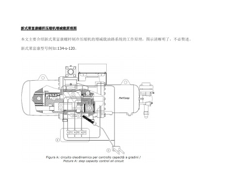
新式莱富康螺杆压缩机增减载原理图

新式莱富康螺杆压缩机增减载原理图
本文主要介绍新式莱富康螺杆制冷压缩机的增减载油路系统的工作原理,图示清晰明了,不必赘述。
新式莱富康型号例如:134-s-120。
上图是总的油路系统和压缩机内部工作原理图。
上图是压缩机开机后,负载25%的状态的运行情况和油路状况
上图是压缩机在50%时候的油路系统状况
上图是压缩机负载加到75%的状态下的油路情况
上图是压缩机满负荷100%状态下,油路运行状况。
综合以上可以看出,新式莱富康螺杆压缩机的增减载方式在结构上,在电磁阀动作上,在容调滑阀的运动方向上,
在容调油活塞的推动作用力方式上,都是与传统的增减载方式有形式上的区别的。
这一点将直接导致现场设备的调试过程中对机组增减载过程的认知,务必详细了解掌握,才能成竹在胸。
螺杆机组使用说明书.带电子膨胀阀.螺杆机.V113A5

PUNP ELECTRONICDM23螺杆机.带电子膨胀阀,电脑控制器厂家使用说明书在安装使用控制器之前,详细阅读该使用说明书!邦普电脑技术开发有限公司2012/08/14软件功能码:X1.DM23C.TY.F40M V113A5版权所有,翻印必究目录一、DM23概述 (1)1.1、性能简介 (1)1.2、安全要求 (2)1.3、上电前的准备 (2)1.4、模块机组控制器系统配置表 (2)二、安装说明 (3)2.1、DM23C外形安装尺寸图: (3)2.2、L Y506外形安装尺寸图: (3)2.3、L Y511外形安装尺寸图: (4)2.4、蓄电池外形安装尺寸图: (4)2.5、开关电源外形安装尺寸图: (5)2.6、DM23C电源、通讯连接示意图: (6)三、流程图 (7)四、机组运行 (8)4.1、开机界面 (8)4.2、运行主界面 (9)4.3、机器设置界面 (9)4.4、用户设置界面 (9)4.5、状态查询界面 (10)4.6、历史记录界面 (11)4.7、使用说明界面 (11)4.8、故障查询界面 (12)五、厂家设置/ (12)5.1、厂家参数设置 (13)5.2、系统数据复位 (14)5.3、修改厂家设置密码 (14)六、机器设置 (15)6.1、机型设置 (15)6.2、探头设置 (16)6.3、时间设置 (17)6.4、开关量定义 (19)6.5、温度界限设置 (20)6.6、温控参数设置 (22)6.7、自定义输出端口参数 (22)6.8、压力传感器参数设置 (23)6.9、膨胀阀参数设置 (24)6.10、膨胀阀驱动模块操作说明 (25)6.11、电流传感器参数设置 (26)6.12、初始化参数 (28)6.13、修改机器设置密码 (28)七、用户设置 (28)7.1、用户参数设置 (28)7.2、星期定时设置 (28)7.3、压缩机使用设置 (28)7.4、时间设置 (29)7.5、对比度设置 (29)7.6、画面设置 (29)7.7、选择语言 (29)7.8、触摸器校准 (29)7.9、修改用户设置密码 (29)7.10、强制动作 (29)八、控制逻辑 (30)8.1、开机操作 (30)8.2、停机操作 (30)8.3、能量调节 (31)8.4、防冻逻辑 (32)8.5、外循环泵功能 (35)8.6、冷却塔风扇 (35)8.7、定时逻辑 (36)8.8、保护 (36)8.9、膨胀阀控制 (36)8.10、密码管理 (36)九、电子膨胀阀 (37)9.1、电子膨胀阀工作原理 (37)9.2、电子膨胀阀动作 (37)9.3、满液式蒸发器回油控制 (37)十、故障诊断 (37)10.1、故障显示 (37)10.2、故障编号以及说明 (38)十一、附录 (41)11.1、LY506模拟量输入类型的跳线设置 (42)11.2、电气连接图 (43)11.2.1、水源热泵机型 (43)11.2.2、水冷冷水机型 (45)11.2.3、电子膨胀阀驱动模块.吸气过热度 (46)11.3版本升级说明 (47)一、DM23概述DM23系列控制器是邦普公司设计生产的一种可编程控制器,采用双微处理器技术,适用于空调领域,可据用户的需要编写程序,使空调系统运行在最佳的状态。
- 1、下载文档前请自行甄别文档内容的完整性,平台不提供额外的编辑、内容补充、找答案等附加服务。
- 2、"仅部分预览"的文档,不可在线预览部分如存在完整性等问题,可反馈申请退款(可完整预览的文档不适用该条件!)。
- 3、如文档侵犯您的权益,请联系客服反馈,我们会尽快为您处理(人工客服工作时间:9:00-18:30)。
3.4.1.1 Serial port configuration 3.4.1.2 Memory registers 3.4.1.3 Holding registers 3.4.1.4 Input registers 3.4.1.5 Coils registers 3.4.1.6 Slave ID number
7
2.3 Instructions for inverter cooling
To provide the necessary cooling of the inverter, the customer has to arrange a tapping from the liquid line and spill it onto the compressor through its dedicated intake (see picture 2). We recommend to tap the refrigerant from the liquid line after the condenser and where you are sure the refrigerant is liquid only, independently on the load conditions. However a liquid filter has to be installed before spilling the liquid into the inverter heat exchanger.
Model
Filter Model Filter
134-I-95 150 A 134-I-100 150 A
134-I-105 150 A 134-I-110 250 A
134-I-125 150 A 134-I-130 250 A
134-I-135 250 A 134-I-140 250 A
134-I-155 250 A 134-I-160 250 A
• The EMI filter insulation class is IP00. Therefore its suitable protection has to be assured depending on the specific application.
• To get rid of the heating generated by the EMI filter, a proper ventilation of its box has to be provided.
5
Important Note: It is mandatory to shield the cables:
• Between electrical panel and control circuit terminal • Between EMI filter and inverter
Important Note: For the following shielded cables it is mandatory to comply with the following prescriptions:
Liquid intake for inverter cooling. Ring fitting for high pressures, ø 8 mm
134 – I S – 100 Compressor optimized for R134a refrigerant 134 – I S – 100 Capacity control via inverter 134 – I S – 100 S Vi = 3,2 (standard)
A Vi = 2,2 ( option) V Variable Vi 2,2 – 2,6 – 3,2 – 4,4 * (option) 134 – I S – 100 Nominal motor power at 70 Hz 5 as last number for Small Size models 0 as last number for Full Size models * Verify the models for which the Vi = 4,4 is achievable Both the Small Size and the Full Size versions consist of 13 models, as reported in table 1:
134-I Series Compressors Handbook manual
Refcomp 134-I Series – Handbook Manual – Technical Sheet IA-00-14-E-X- Contents may change without notice-
SUMMARY
For the compressors of 134-I series the cabling between electrical motor and inverter is made at RefComp factory. The following cablings have to be carried out by the customer instead:
1 Model designation 2 Installation
2.1 Instructions for electrical connections 2.2 EMI Filter 2.3 Instructions for inverter cooling 3 Management of inverter 3.1 Control circuit terminal and cablings 3.2 Control of the inverter 3.3 Hardware management
134-I-175 250 A 134-I-180 250 A
134-I-215 250 A 134-I-220 300 A
134-I-225 300 A 134-I-230 400 A
134-I-245 300 A 134-I-250 400 A
134-I-295 400 A 134-I-300 400 A
3.4.2 Software ISReader
2 134-I Series – Use and Maintenance Manual – Technical Sheet IA-00-14-E-X- Contents may change without notice-
4 Safety frequency modulation 5 Vi control 6 Technical data 7 Performances 8 Application limits 9 Dimensional drawings
3.3.1 Digital Management 3.3.2 Analog Management
Control via voltage signal Control via current signal
3.4 Software management
3.4.1 Protocol of communication MODBUS RTU
134-I Series – Use and Maintenance Manual – Technical Sheet IA-00-14-E-X- Contents may change without notice-
3
1. Model designation
Example: 134 – I S – 100
Power supply input
Signals input
Picture 1: Terminal boards of electrical motor and inverter for models 134-IS-160/180/220
134-I Series – Use and Maintenance Manual – Technical Sheet IA-00-14-E-X- Contents may change without notice-
- Electrical panel EMI filter - EMI filter Compressor - Electrical panel Control circuit terminal
Line terminal board IS220
Terminal lugs
Control circuit terminal
134-I-225 134-I-230
134-I-245 134-I-250
134-I-295 134-I-325 134-I-375
134-I-300 134-I-330 134-I-380
134-I-415 134-I-420
Table 1 : 134-I, Small Series and Full Series
4 134-I Series – Use and Maintenance Manual – Technical Sheet IA-00-14-E-X- Contents may change without notice-
2. Installation
2.1 Instruction for electrical connections
10 m
2.2 EMI Filter
In order to comply with the EMC rules (electromagnetic compatibility), as standard the compressors of 134-I series are delivered together with their own EMI filter (loose). In table 2 you will find the matching between compressors and EMI filters. The installation of such filter is up to the customer, who however has to comply with the following prescriptions:
