HSS钻头说明
上工钻头电子样本

总长 L 133 142
151
160 169
孔加工刀具
槽长 l1
87
HSS-E价格 (元)/支
39
HSS价格(元)/支
涂层
不涂层
30
16
44
32
17
94
50
36
21
55
38
22
59
40
24
101
63
43
25
71
108
/
/
77
114
83
90
-21-
孔加工刀具
规格 d(h8)
15.0 15.25 15.50 15.75 16.00 16.50 17.00 17.50 18.00 18.50 19.00 19.50 20.00
133
87
142
94
151
101
价格 (元) 11.00
12.00
13.00
14.00
15.00
17.00 20.00
规格d (h8)
12.70 12.80 12.90 13.00 13.10 13.20 13.30 13.40 13.50 13.60 13.70 13.80 13.90 14.00 14.1~14.4 14.50 14.6~14.9 15.00 15.1~15.4 15.50 15.6~15.9 16.00 16.1~16.5 16.6~17.00 17.1~17.5 17.6~18.00 18.1~18.5 18.6~19.00 19.1~19.5 19.6~20.00
4
2.80
1.10 1.15
36
14
0.38
钻头的分类

钻头的分类上篇文章我们写到开孔器,本期主题我们就是钻头。
钻头的种类也繁多,我们一一分解。
1高速钢麻花钻(HSS TWIST DRILL BIT),这类钻头是我们最常见的钻头,可以打木头、塑料、金属等材质。
2 锥柄钻头(TAPER SHANGK BIT),这类钻头我们在台钻、钻床上经常看到,经常配合莫式钻夹头使用。
主要加工对象是金属为主,对精度要求很高。
3 支螺钻(AUGER BIT), 头部是一个尖锐的赶锥螺纹,用于木头上钻孔,可以根据工件加工的长度,选择需要的长度,目前本人见到最长为1米。
其柄部主要是六角(HEX)和圆柄(SDS PLUS)。
4 木工钻(WOOD BIT ) ,这类钻头就是小号的支螺钻,头部尖尖,快速定位,钻入木头中。
5 木工扁钻(FLAT BIT ),这类的钻头跟上着很相似,但是难以操作,对新手不友好。
价格很便宜。
6 电锤钻(HAMMERING DRILL BIT ),这类钻头主要钻混泥土和红砖,家庭打孔,放膨胀管,经常使用。
其柄也是分为圆柄和方柄,国外市场基本全是圆柄接头。
购买时候要注意,你的机器是什么款式就行了。
7 冲击钻头(MASORY BIT ),这类钻头跟电锤钻一样的功能,只是他们的配对的机器不一样,常见的手电钻就可以配合使用了。
8 宝塔钻(STEP DRILL BIT),材质跟麻花钻一样,就是麻花钻的亲哥。
这类的钻头分布的尺寸很多,可以从4mm至32mm都可以攻克,一只钻头顶n支麻花钻作用,减少更换钻头的时间和金钱成本。
9 玻璃钻(GLASS BIT),这类钻头大多数用于玻璃是打孔,但也有消费者拿来打瓷砖。
10 霸王钻(MULTI-FUNCTIONED BIT),这类钻头比较网红,可以打n种材质,包括铁、瓷砖、混凝土、铝材等。
也有很多其他的钻头,比如沉孔钻、沙拉钻、锯齿钻、阶梯钻等等,我们不在这一一说明,感兴趣的小伙伴可以去最近的五金店看看,你会发现很多有趣的东西。
高速钢、白钢、硬质合金钢钻头的区别,加工时钻头材质选用的依据
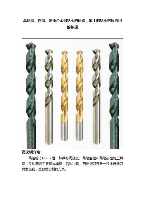
高速钢、白钢、硬质合金钢钻头的区别,加工时钻头材质选用的依据高速钢介绍:高速钢(HSS)是一种具有高硬度、高耐磨性和高耐热性的工具钢,又称高速工具钢或锋钢,俗称白钢。
高速钢刀具是一种比普通刀具要坚韧,更容易切割的刀具。
高速钢名称的由来:高速钢比碳素工具钢具有更好的韧性、强度、耐热性,切削速度比碳素工具钢(铁碳合金)高很多,因此得名高速钢;而硬质合金刚比高速钢的性能更好,切削速度可以再提高2-3倍。
所以常用的钻头都是高速钢和硬质合金钻头!高速钢与合金钻头关系:首先高速钢钻头属于合金钻头!一般的工具钢也属于合金钢只不过是铁碳合金,高速钢的还分普通高速钢和优质高速钢,因此现在合金钻头一般是指硬质合金钻头。
高速钢钻头在高速切削产生高热情况下(约500℃)仍能保持高的硬度,HRC能在60以上。
硬质合金钻头(一般为钨钢材质)具有硬度高、耐磨、强度和韧性较好、耐热、耐腐蚀等一系列优良性能,特别是它的高硬度和耐磨性,即使在500℃的温度下也基本保持不变,在1000℃时仍有很高的硬度。
高速钢钻头和硬质合金钻头材质介绍:高速钢钻头材质是一种成分复杂的合金钢,含有钨、钼、铬、钒、钴等碳化物形成元素。
合金元素总量达10~25%左右。
它在高速切削产生高热情况下(约500℃)仍能保持高的硬度,HRC能在60以上。
这就是高速钢最主要的特性——红硬性。
而碳素工具钢经淬火和低温回火后,在室温下虽有很高的硬度,但当温度高于200℃时,硬度便急剧下降,在500℃硬度已降到与退火状态相似的程度,完全丧失了切削金属的能力,这就限制了碳素工具钢制作切削工具用。
而高速钢由于红硬性好,弥补了碳素工具钢的致命缺点。
高速钢钻头主要用来制造复杂的薄刃和耐冲击的金属切削刀具,也可制造高温轴承和冷挤压模具等,如车刀、钻头、滚刀、机用锯条及要求高的模具等。
钨钢钻头材质(硬质合金)具有硬度高、耐磨、强度和韧性较好、耐热、耐腐蚀等一系列优良性能,特别是它的高硬度和耐磨性,即使在500℃的温度下也基本保持不变,在1000℃时仍有很高的硬度。
信诺蓝色钻头和扁孔头工具说明书

TRUST BLUE■Drilling and countersink tools from a single source■Drills and countersinks for nearly all materials and applications■Highest degree of quality for precise and neat resultsDrilling toolsHSS spiral drills 3■DIN 338 HSSG N STEEL spiral drills 6■DIN 338 HSSE N INOX spiral drills 8HSS step drills 10■HSS step drills 12■HSS step drills with HICOAT coating HC-FEP 13Countersink toolsHSS conical countersinks 14■HSS DIN 335 C 90° conical countersinks 16■HSSE DIN 335 C 90° conical countersinks, Co5 type 17■HSS DIN 335 C 90° conical countersinkswith HICOAT coating HC-FEP 18■HSS DIN 334 C 60° conical countersinks 19HSS flat countersinks 20■HSS DIN 373 flat countersink quality grade fine for through hole 22■HSS DIN 373 flat countersink quality grade medium for through hole 22■HSS DIN 373 flat countersinks for tapping hole 23TC ground contact countersinks 24Drilling tools with cross grinding for industrial uses. Fully ground, right-hand turning versions that produce precise drill holes thanks to their high concentricity and exact centring. PFERD offers spiral drills in the STEEL (118° point angle) and INOX (135° point angle) types.Advantages:■Very good chip removal. ■High concentricity.■Exact centring and low feed force thanks to cross grinding.Applications:■DrillingRecommendations for use:■Observe the recommended rotational speed.■When drilling metals, use a high-quality cutting oil or cooling lubricant, if possible. This facilitates smooth running andextends the drill tool life. Exception: when working on aluminium, use kerosene instead of cutting oil.■In order to avoid corrosion, remove any particles which develop when working on stainless steel (INOX) from the workpiece. Clean the workpiece chemically or mechanically (etching/polishing, etc.).Safety notes:=Wear eye protection!=Follow the safety instructions!Matching tool drives:■Power drills ■Column drills ■Machine tools ■RobotExample applications for STEEL/INOX HSS spiral drillsHSSG (M2) STEEL 118° type■Suitable for universal use on steel, cast steel, grey cast iron, annealed cast iron, bronze, brass, aluminium. ■Easy centring. ■Long tool life.■Good chip removal.HSSE Co5 (M35) INOX 135° type■Particularly well suited for tough and hard materials, such as alloyed and high-strength steel, stainless steel (INOX). ■Robust tip profile. ■Very long tool life. ■Good chip removal.■Very good temperature resistance due to Co content.Recommended rotational speed range [RPM]To determine the recommended cutting speed range [m/min], please proceed as follows:➊ S elect the material group to be machined.➋ Select the type.➌ Establish the cutting speed range.To determine the recommended rotational speed range [RPM], please proceed as follows:➍ S elect the required diameter.➎ T he cutting speed range and the diameter determine the recommended rotationalspeed range.Fully ground spiral drill with cross grindingPFERD drills are completely ground spiral drills: they are precision ground both in the chip flute and the guide chamfer as well as at the drill tip. They also have cross grinding. This drill is suitable for highly precise positioning on the workpiece and supports centring during drilling. This grinding finish even cuts at the centre of the drill tip and reduces the feed forces during use. Spiral drills with cross grinding are suitable for purposes including machining of difficult-to-machine materials like chromium-nickel steel.Example:Spiral drill,SPB DIN 338 HSSG N 12,0 STEEL, Tool dia. 12 mm.Steels up to 700 N/mm²Cutting speed: 25–35 m/min.Rotational speed range: 650–950 RPMDIN 338 HSSG N STEEL spiral drills Array High-performance drilling tools in the STEEL in HSSG (M2) type for industrial uses.Fully ground, right-hand turning version with cross grinding.Materials that can be worked:■steel, aluminium, brass, bronze, cast,plasticsSTEELEAN 4007220DIN 338 HSSG N STEEL spiral drills, 19-piece setThe set contains 19 HSS spiral drills in the STEEL in HSSG (M2) type for industrial uses. The sturdy plastic box protects the tools from dirt and damage.The securing of the HSS spiral drills facilitates the selection and withdrawal of the tools.Contents:19 HSS spiral drills,STEEL in HSSG (M2) type,dia. 1.0 to 10.0 mm, graduations in 0.5 mm Materials that can be worked:■steel, aluminium, brass, bronze, cast, plasticsSTEEL EAN 4007220DIN 338 HSSG N STEEL spiral drills, 25-piece setThe set contains 25 HSS spiral drills in the STEEL in HSSG (M2) type for industrial uses. The sturdy plastic box protects the tools from dirt and damage.The securing of the HSS spiral drills facilitates the selection and withdrawal of the tools.Contents:25 HSS spiral drills,STEEL in HSSG (M2) typedia. 1.0 to 13.0 mm, graduations in 0.5 mm Materials that can be worked:■steel, aluminium, brass, bronze, cast, plasticsSTEEL EAN 4007220DIN 338 HSSE N INOX spiral drills Array High-performance drilling tools in the INOX in HSSE-Co5 (M35) type for industrial uses. Fully ground, right-hand turning version with cross grinding.Materials that can be worked:■steel, stainless steel (INOX), aluminium,brass, bronze, cast, titanium, plasticsINOXEAN 4007220DIN 338 HSSE N INOX spiral drills, 19-piece setThe set contains 19 HSS spiral drills in the INOX in HSSE-Co5 (M35) type for industrial uses. The sturdy plastic box protects the tools from dirt and damage. The securing of the HSS spiral drills facilitates the selection and withdrawal of the tools.Contents:19 HSS spiral drills,INOX in HSSE-Co5 (M35) type,dia. 1.0 to 10.0 mm, graduations in 0.5 mm Materials that can be worked:■steel, stainless steel (INOX), aluminium, brass, bronze, cast, titanium, plasticsINOXEAN 4007220DIN 338 HSSE N INOX spiral drills, 25-piece setThe set contains 25 HSS spiral drills in the INOX in HSSE-Co5 (M35) type for industrial uses. The sturdy plastic box protects the tools from dirt and damage. The securing of the HSS spiral drills facilitates the selection and withdrawal of the tools.Contents:25 HSS spiral drills,INOX in HSSE-Co5 (M35) typedia. 1.0 to 13.0 mm, graduations in 0.5 mm Materials that can be worked:■steel, stainless steel (INOX), aluminium, brass, bronze, cast, titanium, plasticsINOX EAN 4007220Sturdy high-performance tools for burr-free drilling and deburring of sheet metal, pipes and profiles. Materials up to 4 mm thick can be drilled and deburred easily in a single step. PFERD also offers step drills with a high-quality HICOAT coating. To ensure reliable torque transmis-sion, all step drills have a three-surface shaft.Advantages:■Drilling and deburring in a single step.■Completely smooth running and a high cutting performance.■The high-quality drill tip ensures effortless centring and drilling.■The tool taper makes it easier to pull back from drilled plates.■Chips which do not break are neatly removed as with a spiral drill.■Built-up edges and cold welding on the blades are prevented. Materials that can be worked:■Steel■Cast steel■Stainless steel (INOX)■Non-ferrous metals■Plastics■Other materials Applications:■Drilling■Deburring Recommendations for use:■Use HSS step drills on sheets, pipes and profiles with a maximum thickness of 4 mm.■Please refer to the table for the recommended rotational speeds. Matching tool drives:■Power drills■Column drillsSafety note:To ensure reliable torquetransmission, step drillshave a three-surface shaft.HSS type■Use cutting oil/compressed air as a coolantand lubricant in the case of step drillswithout a coating.HSS HICOAT HC-FEP type■Step drills with a HICOAT coating can alsobe used without the addition of coolants.■Particularly suitable for work on stainlesssteel (INOX).Recommended rotational speed range [RPM]To determine the recommended cutting speed range [m/min], please proceed as follows:➊S elect the material group to be machined.➋ Select the type.➌ Establish the cutting speed range.To determine the recommended rotational speed range [RPM], please proceed as follows:➍S elect the required diameter.➎T he cutting speed range and the diameter determine the recommended rotationalspeed range.Example:HSS step drillsSTB HSS 04-30/10,Step dia. 4–30 mm. Steels up to 700 N/mm². Cutting speed: 20–30 m/minRotational speed range: 2,400–200 RPMl2HSSEAN 4007220HSS step drills, 3-piece setThe set includes three HSS step drills in the versions 4–12 mm (9 steps), 4–20 mm (9 steps),4–30 mm (14 steps) for industrial uses. To ensure reliable torque transmission, all step drillshave a three-surface shaft.The sturdy plastic box protects the tools from dirt and damage. The securing of the HSS stepdrills facilitates the selection and withdrawal of the tools.HSSEAN 4007220HSS step drillsHSS step drills for drilling and deburring thin sheets, pipes and profiles made from variousmaterials. To ensure reliable torque transmission, all step drills have a three-surface shaft.l2HSS step drills with HICOAT coating HC-FEPHSS step drills with premium HICOAT coating HC-FEP are wear resistant and versatile as they can be used to process steel, stainless steel (INOX), non-ferrous metals, thermoplastics and duroplastics. To ensure reliable torque transmission, all step drills have a three-surface shaft.Step drills with a HICOAT coating HC-FEP provide good high-temperature hardness and resist-ance to oxidation. They can therefore also be used on hard materials without the addition of coolants.HC-FEPEAN 4007220HSS step drills with HICOAT coating HC-FEP, 3-piece setThe set includes three HSS step drills in the versions 4–12 mm (9 steps), 4–20 mm (9 steps), 4–30 mm (14 steps) with a premium HICOAT coating HC-FEP for industrial uses. To ensure reliable torque transmission, all step drills have a three-surface shaft.The sturdy plastic box protects the tools from dirt and damage. The securing of the HSS step drills facilitates the selection and withdrawal of the tools.HC-FEPEAN 4007220Conical countersinks from PFERD are characterized by their particularly sharp right-hand blades that are able to achieve very good results, even at low cutting speeds. The various types allow for countersinking and deburring when machining various types of materials, even in industrial environments. To ensure reliable torque transmission, conical countersinks have a three-surface shaft from a countersink diameter of 28 mm.PFERD also offers conical countersinks with a premium HICOAT coating. Tapered countersinks with a HICOAT coating provide good high-temperature hardness and resistance to oxidation. They can therefore also be used on hard materials without the addition of coolants.Advantages:■Very high stock removal rate and optimum chip removal.■Burr-free results, even with low cutting speeds.■Long tool life.■High surface quality of the workpiece. Materials that can be worked:■Steel■Cast steel■Stainless steel (INOX)■Non-ferrous metals■Cast iron■Plastics■Other materials Applications:■Chamfering■Deburring■Countersinking Recommendations for use:■Select the appropriate type depending on the countersink angle required and the material to be machined.■Use cutting oil or compressed air as a coolant and lubricant.■Please refer to the table for the recommended rotational speeds. Matching tool drives:■Power drills■Column drills■Machine tools■RobotSafety note:To ensure reliable torquetransmission, conicalcountersinks have athree-surface shaft froma countersink diameter of28 mm.HSS countersinks 90°■Particularly well suited for producingcountersinks for 90° screws.HSS countersinks 60°■Particularly well suited for countersinkingand deburring.HSS type HSS E Co5 (M35) type HSS HICOAT HC-FEP type■HSS countersink that is suitable foruniversal use on almost all materials.■HSS countersink that is suitable foruniversal use on almost all materials.■Long tool life.■Very good temperature resistance due toCo content.■HSS countersink that is suitable foruniversal use on almost all materials.■Very long tool life thanks to premiumHICOAT coating.■Can also be used without coolants andlubricants.Recommended rotational speed range [RPM]To determine the recommended cutting speed range [m/min], please proceed as follows:➊S elect the material group to be machined.➋ Select the type.➌ Establish the cutting speed range.To determine the recommended rotational speed range [RPM], please proceed as follows:➍S elect the required diameter.➎T he cutting speed range and the diameter determine the recommended rotationalspeed range.Example:Conical countersink KES HSS DIN 335 90°, countersink dia. 28.0 mm. Steels up to 700 N/mm². Cutting speed: 15–20 m/minRotational speed range: 170–220 RPMHSS DIN 335 C 90° conical countersinksHigh-performance countersink tools with a countersink angle of 90° for countersinking 90° screws for all common materials such as steel, cast steel and non-ferrous metals. To ensure reliable torque transmission, conical countersinks have a three-surface shaft from a countersink diameter of 28 mm.Materials that can be worked:■steel, cast steel, stainless steel (INOX), non-ferrous metals, cast iron, plastics, other materialsHSS EAN 4007220HSS DIN 335 C 90° conical countersink setsThe sets include high-performance countersink tools with a countersink angle of 90° for countersinking 90° screws for all common materials such as steel, cast steel and non-ferrous metals. The sturdy plastic box protects the tools from dirt and damage.Materials that can be worked:■steel, cast steel, stainless steel (INOX), non-ferrous metals, cast iron, plastics, other materialsOrdering notes:■Select the set depending on the number of types required.HSSEAN 4007220l 1HSSE DIN 335 C 90° conical countersinks, Co5 typeHigh-performance countersink tools with a countersink angle of 90° for countersinking 90° screws for particularly tough and hard materials such as alloyed and high-strength steel and stainless steel (INOX). To ensure reliable torque transmission, conical countersinks have a three-surface shaft from a countersink diameter of 28 mm. Long tool life and temperature-resistant type due to Co content. Materials that can be worked:■steel, cast steel, stainless steel (INOX), non-ferrous metals, cast iron, plastics, other materialsHSSE EAN 4007220l 1HSSE DIN 335 C 90° conical countersink sets, Co5 typeThe sets include high-performance countersink tools with a countersink angle of 90° forcountersinking 90° screws for particularly tough and hard materials such as alloyed and high-strength steel and stainless steel (INOX). Long tool life and temperature-resistant type due to Co content. The sturdy plastic box protects the tools from dirt and damage.Materials that can be worked:■steel, cast steel, stainless steel (INOX), non-ferrous metals, cast iron, plastics, other materialsOrdering notes:■Select the set depending on the number of types required.HSSEEAN 4007220HC-FEP EAN 4007220HSS DIN 335 C 90° conical countersinks with HICOAT coating HC-FEPHigh-performance countersink tools with a countersink angle of 90° for countersinking 90° screws for particularly tough and hard materials such as alloyed and high-strength steel and stainless steel. To ensure reliable torque transmission, conical countersinks have a three-surface shaft from a countersink diameter of 28 mm. Thanks to the HICOAT coating HC-FEP, they have high hardness and wear resistance. They are very temperature resistant and have a particularly long tool life. They can also be used in a higher cutting speed range and without coolants and lubricants.Materials that can be worked:■steel, cast steel, stainless steel (INOX), non-ferrous metals, cast iron, plastics, other materialsl 1HSS DIN 335 C 90° conical countersink sets with HICOAT coating HC-FEPThe sets include high-performance countersink tools with a countersink angle of 90° forcountersinking 90° screws for particularly tough and hard materials such as alloyed and high-strength steel and stainless steel (INOX). Thanks to the HICOAT coating HC-FEP, they have high hardness and wear resistance. They are very temperature resistant and have a particularlylong tool life. They can also be used in a higher cutting speed range and without coolants and lubricants. The sturdy plastic box protects the tools from dirt and damage.Materials that can be worked:■steel, cast steel, stainless steel (INOX), non-ferrous metals, cast iron, plastics, other materialsOrdering notes:■Select the set depending on the number of types required.HC-FEPEAN 4007220HSS EAN 4007220HSS DIN 334 C 60° conical countersinksHigh-performance countersink tools with a countersink angle of 60° for deburring all common materials such as steel, cast steel and non-ferrous metals.Materials that can be worked:■steel, cast steel, stainless steel (INOX), non-ferrous metals, cast iron, plastics, other materialsl1High-performance flat countersinks made from HSS according to DIN 373 for countersinking cylinder head and hexagon screws as well as nuts. Flat countersinks have a cylindrical design. The cylindrical pilot in the relevant quality grades of fine, medium or tapping hole ensures coaxial alignment of the countersink to the bore.Advantages:■Very high stock removal rate.■Optimum chip removal.■Burr-free results.■Long tool life.■Smooth operation.■Good surface quality.Materials that can be worked:■Steel■Cast steel■Stainless steel (INOX)■Non-ferrous metals■Cast iron■Plastics■Other materialsApplications:■Produce flat countersinks in the qualitygrades fine (F), medium (M) and tappinghole (GKL).Recommendations for use:■Please observe the recommendedrotational speed.Matching tool drives:■Power drills■Column drills■Machine tools■RobotQuality grade fine (F)Quality grade medium (M)For tapping hole (GKL)■Flat countersinks with the quality gradeof fine are suitable for producing flatcountersinks at through holes or blindholes in the tolerance range of fine withhigh mounting accuracy.■Flat countersinks with the quality grademedium are suitable for producing flatcountersinks at through holes or blindholes in the tolerance range of mediumwith extended mounting accuracy.■Flat countersinks for the tapping hole aresuitable for producing flat countersinks atcore holes for female threads.Recommended rotational speed range [RPM]To determine the recommended cutting speed range [m/min], please proceed as follows:➊S elect the material group to be machined.➋ Select the type.➌ Establish the cutting speed range.To determine the recommended rotational speed range [RPM], please proceed as follows:➍S elect the required diameter.➎T he cutting speed range and the diameter determine the recommended rotationalspeed range.Example:Flat countersinkFLS HSS DIN 373 15,0 F, Flat countersink dia. 15 mm. Steels up to 700 N/mm². Cutting speed: 10–20 m/minRotational speed range: 220–440 RPMF EAN 4007220HSS DIN 373 flat countersink quality grade fine for through holeHigh-performance countersink tools for through holes with the quality grade fine (F) according to ISO 273.Materials that can be worked:■steel, cast steel, stainless steel (INOX), non-ferrous metals, cast iron, plastics, other materials2M EAN 4007220HSS DIN 373 flat countersink quality grade medium for through holeHigh-performance countersink tools for through holes with the quality grade medium (M) according to ISO 273.Materials that can be worked:■steel, cast steel, stainless steel (INOX), non-ferrous metals, cast iron, plastics, other materials2GKL EAN 4007220HSS DIN 373 flat countersinks for tapping holeHigh performance countersink tools with guide pilots for the tapping hole (GKL). Materials that can be worked:■steel, cast steel, stainless steel (INOX), non-ferrous metals, cast iron, plastics, other materials23/2020S u b j e c t t o t e c h n i c a l m o d i fi c a t i o n s .PFERD produces TC ground contact countersinks flexibly and precisely according to the cus -tomer‘s specifications. They are used to produce precisely circular ground contact points. Com -pared to the use of brushes, not only are precise ground contact points achieved, but also high surface qualities for optimum conductivity. Thanks to their depth gauge, the stock removal is predefined extremely precisely. The tools meet the guidelines from well-known manufacturers from aircraft construction since they were developed together with aircraft manufacturers in order to be used in the manufacture and maintenance of airplanes and helicopters.Contact us in order to develop your individual tool solution together with us. Our worldwide sales addresses and contact details can be found at .Advantages:■Special solution for producing precisely defined circular ground contact points. ■Low contact resistance/top conductivity due to milled surface instead of brushed surface and chips instead of dust.■Precisely defined stock removal thanks to depth gauge.■Good dimensional accuracy compared to the brush.■Extremely high tool life with consistent quality from the first to the last use.■Flexible tool design according to the cus-tomer‘s wishes with close tolerances. ■Coordinated drive and tool from a single source.Materials that can be worked:■Aluminium■Painted or otherwise treated surfacesRecommendations for use:■Use the TC ground contact countersinkswith a rotational speed of 400 RPM.Contact us for further information on these special tool drives.Our worldwide sales addresses and contact data can be found at .Matching tool drives:SP = keyless fast clamping system S = changing tools with 2 keys ➊T M-B DEB 1/004 45° S3Rotational speed: max. 400 RPM Power: 2 watts286253023➋ TM-B DEB 1/004 90° S3Rotational speed: max. 400 RPM Power: 2 watts232528130➌ TM-B DEB 1/004 SP3Rotational speed: max. 400 RPM Power: 2 watts15288253023。
绳索取芯钻具使用说明书[1]
![绳索取芯钻具使用说明书[1]](https://img.taocdn.com/s3/m/52a71b8ebb4cf7ec4afed0da.png)
绳索取芯钻具使用说明书一、概述绳索取心钻进又叫不提钻取芯钻进,它的特点是当岩芯装满内管时,不提钻而用绳索打捞器从钻杆内把内管捞取上来获得岩芯。
因其结构简单、钻进效率高、岩(矿)芯采取率高、劳动强度低、钻探成本低等显著优点,而广泛使用。
我厂生产的绳索取芯钻具已确定为“S”系列产品:S59、SJ75、S75、S96。
其具体规格见下表:为使用户更好的掌握这项先进的技术,正确的使用我厂生产的S系列绳索取芯钻具及附属设备工具,充分发挥绳索取芯钻进的优越性,特编此书,以供使用参考。
二、绳索取芯钻具的结构和工作原理目前我国使用的绳索取芯钻具结构和工作原理基本相同。
经过生产实践和不断改进,各种钻具均灵活可靠,效果良好,取芯成功率高。
(一)绳索取芯钻具结构主要由单动双管和打捞器两大部分组成。
双管部分由外管总成和内管总成组成。
而外管总成包括弹卡挡头、弹卡室、扩孔器、外管和金刚石钻头组成。
内管总成包括捞矛头、弹卡、单动组件、报警、调节组件、内管、悬挂扶正及卡芯组件组成。
(二)几个主要机构的功用和动作原理1、捞矛机构需要取芯时,打捞器从钻杆内下放到内管总成上端,打捞钩钩住捞矛(矛头)。
向上提升打捞器,捞矛头通过弹簧销向上提升回收管,迫使弹卡钳收缩,这样使内管总成与外管总成脱离,从而把内管提升上来。
2、弹卡机构即定位机构,主要由弹卡架、弹卡钳、张簧等部件组成。
其作用是使内管座到外管中时,弹卡钳借助张簧的张力而张开,贴在弹卡室的内壁上。
其上端有弹卡挡头的拨叉,带动钻具轴承上部和外管同时旋转,防止弹卡磨损。
3、单动机构钻具的单动主要靠两盘推力轴承来实现。
4、调节机构内外管总成的长度,主要通过调节接头和调节螺母进行调节。
达到卡弹簧座底端与钻头内台阶所要求的间隙(3-4mm),减少岩芯受冲洗机会。
在使用过程中,由于内管零部件尺寸的变化,卡簧座与钻头内台阶的间隙亦随之变化。
为了保证岩矿芯采取率,减少残留岩芯,故应及时调节。
5、悬挂机构在悬挂接头下端有一个可拆卸的悬挂环,内管总成到达外管总成中的预定位置时,悬挂环坐落在座环上。
高速钢HSS
高速钢1. 概述高速钢High Speed Steels又名风钢或锋钢,意思是淬火时即使在空气中冷却也能硬化,并且很锋利。
它是一种成分复杂的合金钢,含有钨、钼、铬、钒、钴等碳化物形成元素。
合金元素总量达10~25%左右。
它在高速切削产生高热情况下(约500℃)仍能保持高的硬度,HRC 能在60以上。
这就是高速钢最主要的特性——红硬性。
而碳素工具钢经淬火和低温回火后,在室温下虽有很高的硬度,但当温度高于200℃时,硬度便急剧下降,在500℃硬度已降到与退火状态相似的程度,完全丧失了切削金属的能力,这就限制了碳素工具钢制作切削工具用。
而高速钢由于红硬性好,弥补了碳素工具钢的致命缺点,可以用来制造切削工具。
高速钢的热处理工艺较为复杂,必须经过退火、淬火、回火等一系列过程。
退火的目的是消除应力,降低硬度,使显微组织均匀,便于淬火。
退火温度一般为860~880℃。
淬火时由于它的导热性差一般分两阶段进行。
先在800~850℃预热(以免引起大的热应力),然后迅速加热到淬火温度1190~1290℃(不同牌号实际使用时温度有区别),后油冷或空冷或充气体冷却。
工厂均采用盐炉加热,现真空炉使用也相当广泛。
淬火后因内部组织还保留一部分(约30%)残余奥氏体没有转变成马氏体,影响了高速钢的性能。
为使残余奥氏体转变,进一步提高硬度和耐磨性,一般要进行2~3次回火,回火温度560℃,每次保温1小时。
(1)生产制造方法:通常采用电炉生产,近来曾采用粉末冶金方法生产高速钢,使碳化物呈极细小的颗粒均匀地分布在基体上,提高了使用寿命。
(2)用途:用于制造各种切削工具。
如车刀、钴头、滚刀、机用锯条及要求高的模具等。
2. 主要生产厂我国上钢五厂、河冶科技是生产高速钢的主要生产厂。
3. 主要进口生产国家我国主要从日本、俄罗斯、德国、奥地利、法国、乌克兰、巴西等国进口。
4. 种类有钨系高速钢、钼系高速钢和钴系高速钢三大类。
钨系高速钢有W 18 CR 4 V,钼系高速钢有W 6 Mo 5 Cr 4 V 2 ,钴系高速钢有W6Mo 5Cr 4 V 2Co5、W 2 Mo 9 Cr 4 V Co 8等。
微孔加工方法
微孔加工方法在孔加工过程中,应防止出现孔径扩大、孔直线度过大、工件表面粗拙度差及钻头过快磨损等问题,以防影响钻孔质量和增大加工成本,应尽量保证以下的技术要求 : ①尺寸精度:孔的直径和深度尺寸的精度;②形状精度:孔的圆度、圆柱度及轴线的直线度;③地点精度:孔与孔轴线或孔与外圆轴线的同轴度;孔与孔或孔与其余表面之间的平行度、垂直度等。
同时,还应当考虑以下5个因素:1.孔径、孔深、公差、表面粗拙度、孔的构造;2.工件的构造特色,包含夹持的稳固性、悬伸量和展转性;3.机床的功率、转速冷却液系统和稳固性;4.加工批量;5.加工成本。
深孔加工:一般把长径比 L( 孔深与孔径比 ) 大于 5 的孔称为深孔。
深孔加工比一般孔的加工要困难和复杂,其原由是:1.因为孔深与孔径比较大,刀具细而长、刚性差,所以在钻孔时简单偏斜,产生振动,使得孔的表面粗拙度和尺寸精度不易保证。
2.钻削时排屑困难。
3.热量不易排出,钻头散热条件差,使得刀具磨损加剧,甚至丧失切削能力。
机械钻削加工一、 HSS-E(高性能高速钢)钻头因为长钻头自己的稳固度不好,所以在加工过程中一定采纳较低的切削参数,而 HSS较低的红硬性也要求进一步降低其切削速度。
因此,在深孔加工中,外面的冷却液很难抵达刀具的切削刃上,钻尖处实质进行着干加工,所有这些因素的综合致使了深孔加工需要很长的加工周期。
二、枪钻硬质合金头枪钻能够实现精准而安全的孔加工,即便是在进行超常深孔的加工状况下也是这样。
切削液被加压泵打入钻杆内( 压力约为3MPa-8MPa),而后流过切削刃,当切削液沿着刀具和零件孔壁间的V形截面空间流出时,将切屑带走。
因为钻杆是空心轴,刚性差,不可以采纳较大的进给量,因今生产效率较低;同时,切屑一定保持小而薄的形状,才能保证被冷却液冲出;别的,因为枪钻加工中高压冷却液的使用,所以要求使用专用机床。
因为枪钻钻杆为非对称形,故其抗扭刚性差,只好传达有限的扭矩,所以枪钻只合用于加工小直径孔的零件。
金刚石绳索取芯钻头的正确使用
金刚石绳索取芯钻头的正确使用【摘要】近年来,随着金刚石绳索取芯技术的普及,金刚石绳索取芯钻头的使用寿命以及使用率就很大程度上的影响了工程的整体收益效益,所以,研究金刚石绳索取芯钻头的正确使用就有了重要的现实意义。
【关键词】金刚石绳索取芯钻头;正确使用一、前言金刚石绳索取芯技术由于钻进效率高等一系列优点,被广泛应用于地质勘探、煤田勘探等场合。
正确的使用金刚石绳索取芯钻头,可以为整个工程节省出很大一部分资金,扩大自己的收益。
所以,如何正确的使用金刚石绳索取芯钻头对很多领域来说,都是一个迫切需要弄明白的问题。
现在大批民营钻探队伍进入钻探行业,但其员工大多缺乏金刚石钻探工具的操作技术。
二、金刚石绳索取芯技术的优越性金刚石钻进技术要求要远远高于硬质合金或牙轮钻进技术。
金刚石运用于钻探.是钻探技术的一次飞跃。
随着金刚石钻头质量和性能的提高以及品种的增多,将岩心钻探中的主要矛盾转移到岩心提取方面。
合理的钻具组合可以大大减少井内事故,提高岩心采取率,降低钻井全角变化率,提高钻月效率。
金刚石取心钻具组合大致可分为三种:单管钻具、普通双管钻具、绳索取心双管钻具。
而绳索取芯钻探技术的开发运用,将这一工作提高到了一个新的水平。
大大降低了辅助时间,减轻了劳动强度。
上世纪七十年代以来,金刚石绳索取心钻进工艺由于其自动化程度高、井内事故少、取芯率及钻进效率高的优势,在煤田勘探及石油勘探施工中得到了迅速的推广。
近十年来,金刚石绳索取芯钻进在煤层气参数井施工中又得到了进一步的发展。
其相对于普通金刚石取芯技术主要有优点如下:1、实现了较大间段不提钻连续取心,显著降低钻进辅助时间,大大提高了生产效率。
当岩心装满或堵塞时,钻具报讯,此时只需将机上主动钻杆提移孔口,用绳索把专用打捞器从钻杆中下入钻杆内,即可将内管连同岩心提出孔外。
然后将空的内管总成投入,实现连续钻进。
而对于普通取心钻进900m深的孔,整个提取岩心过程,一般需用50~70分钟,甚至更多。
HSS含意

HSS含意高速钢是一种含多量碳(C)、钨(W)、钼(Mo)、铬(Cr)、钒(V)等元素的高合金钢,热处理后具有高热硬性。
当切削温度高达600℃以上时,硬度仍无明显下降,用其制造的刀具切削速度可达每分钟60米以上,而得其名。
高速钢按化学成分可分为普通高速钢及高性能高速钢,按制造工艺可分为熔炼高速钢及粉末冶金高速钢。
普通高速钢高速钢是制造形状复杂、磨削困难的刀具的主要材料。
普通高速钢可满足一般需求。
常见的普通高速钢有两种,钨系高速钢和钨钼系高速钢。
钨系高速钢典型牌号为w18Cr4V,热处理硬度可达63-66HRC,抗弯强度可达3500MPa,可磨性好。
• 钨钼系高速钢典型牌号为W6Mo5Cr4V2,目前正在取代钨系高速钢,具有碳化物细小分布均匀,耐磨性高,成本低等一系列优点。
热处理硬度同上,抗弯强度达4700MPa,韧性及热塑性比w18Cr4V提高50%。
常用于制造各种工具,例如钻头、丝锥、铣刀、铰刀、拉刀、齿轮刀具等,可以满足加工一般工程材料的要求。
只是它的脱碳敏感性稍强。
另一牌号的普通高速钢为W9Mo3Cr4V,这是中国近几年发展起来的新品种。
强度及热塑性略高于W6Mo5Cr4V2,硬度为HRC63-64,与韧性相配合,容易轧制、锻造,热处理工艺范围宽,脱碳敏感性小,成本更低。
这三个牌号的普通高速钢在中国市场的比例分别为:W18Cr4V,16.5%;W6Mo5Cr4V2 69%;W9Mo3Cr4V11%。
高性能高速钢高性能高速钢具有更好的硬度和热硬性,这是通过改变高速钢的化学成分,提高性能而发展起来的新品种。
它具有更高的硬度、热硬性,切削温度达摄氏650度时,硬度仍可保持在60HRC以上。
耐用性为普通高速钢的1.5-3倍,适用于制造加工高温合金、不锈钢、钛合金、高强度钢等难加工材料的刀具。
主要品种有4种,分别为高碳系高速钢、高钒系高速钢、含钴系高速钢和铝高速钢。
• 高碳系高速钢牌号为9w18Cr4V,因含碳量高(0.9%),故硬度、耐磨性及热硬性都比较好。
合金钻头转速和进给参数表
合金钻头转速和进给参数表合金钻头是一种常用的切削工具,广泛应用于工业生产和建筑施工中。
合金钻头的转速和进给参数是使用合金钻头时需要考虑的重要因素。
本文将从转速和进给参数两个方面来介绍合金钻头的应用。
一、合金钻头转速参数的选择合金钻头的转速是指钻头在旋转过程中的转速,它直接影响到钻头的切削效果和工作效率。
合金钻头的转速应根据具体的工作材料和钻头直径来选择。
1. 工作材料:不同的材料有不同的硬度和切削性能,因此需要根据工作材料来选择合适的转速。
例如,对于较硬的金属材料,转速应选择较高,以提高切削效果;而对于较软的材料,转速应选择较低,以避免过度切削。
2. 钻头直径:钻头直径的大小也会对转速的选择产生影响。
一般来说,钻头直径较大时,转速应选择较低,以保证切削效果和工作稳定性;而钻头直径较小时,转速可以适当增加,以提高工作效率。
3. 可用速度范围:合金钻头的转速有一个可用的速度范围,通常在钻头的产品说明书或技术参数表中可以找到。
在选择转速时,应确保转速在这个范围内,以保证钻头的正常工作和使用寿命。
二、合金钻头进给参数的选择合金钻头的进给参数是指钻头在钻削过程中每转一圈所进给的距离,它也会对钻头的切削效果和工作效率产生影响。
进给参数的选择应综合考虑以下几个因素:1. 工作材料:不同的材料对进给参数的要求也不同。
一般来说,对于较硬的材料,进给速度应选择较低,以避免过度切削和损伤钻头;而对于较软的材料,进给速度可以适当增加,以提高工作效率。
2. 钻头直径:钻头直径的大小也会对进给参数的选择产生影响。
钻头直径较大时,进给速度应选择较低,以保证切削效果和工作稳定性;而钻头直径较小时,进给速度可以适当增加,以提高工作效率。
3. 钻孔深度:钻孔深度较大时,进给速度应选择较低,以避免钻头过热和提高钻孔质量;而钻孔深度较小时,进给速度可以适当增加,以提高工作效率。
合金钻头的转速和进给参数是使用合金钻头时需要重点考虑的因素。
钻头基础介绍

优点: • 定位好 • 加工精度高
缺点: • 钻尖强度差 • 受力分布不理想
• 孔口无毛刺
by Xu_Hanguang
The Tool Company
高速钢钻头
by Xu_Hanguang
The Tool Company Art.-Nr. 653
DIN 最大钻深 1897 DZ DZ (3xD) 338 (5xD) 339 DZ DZ DZ DZ DZ DZ DZ 340 DZ DZ DZ 1869 Series 1 Series 2 Series 3
直柄麻花钻 Type VA (V2A/V4A)
圆弧后刀面 顶角: 130 度 螺旋角: 比标准的(30度)大 钻芯锥度: 标准 直径公差 Ø : h 8 螺旋角 35度
by Xu_Hanguang
The Tool Company
HSS 直柄麻花钻
带内冷孔
标准品范围: 3 ~13,00 mm
by Xu_Hanguang
by Xu_Hanguang
(5xD)
S S F F
FN
S S F F
FN
S S F F
502 503 504 670 671
FN FN FN
618 619
FN FN
S S
S S
The Tool Company
麻花钻 GT100(抛物钻)
刃带氮化处理
TIN coated
FireX coated
S S
S
D
S
Type N – 圆柱柄
螺旋角 = 20°-30° 圆弧后刀面 顶角 = 118° 标准钻头,主要用来加工拉伸强度不超 过1200 N/mm² 合金或非合金钢, 灰铸铁, 球墨铸铁 以及 粉末金属
(仅供参考)高速钢钻头及硬质合金钻头切削用量的选用

加工材料钻头直径(ød)切削速度V(m/min)进给量f(mm/r)进给速度F(mm/min)加工材料钻头直径(ød)切削速度V(m/min)进给量f(mm/r)进给速度F(mm/min) 623.60.11251075.40.15360 825.50.121221589.50.18342 1025.10.1411220103.60.22363 15260.189925117.80.25375 2025.50.2289301130.28336 25240.2576351040.3285 30220.286540100.50.33264 35200.35540190.35531062.80.2400 45170.42501584.80.22396 60150.5402094.20.25375251020.28364 620.70.151653094.20.3300 823.90.21903593.40.33280 1023.60.261954087.90.35245 1525.90.321762025.10.381522527.50.421473026.40.481343519.80.529440150.55664514.10.6606014.10.65492. 对孔的精度要求较高或孔表面粗糙度要求较高时,内冷充分冷却。
高速钢钻头的切削用量(推荐值)铸铁(HB120~225)硬质合金钻头的切削用量(推荐值)碳素结构钢和优质碳素结构钢(HB125~225)铸铁(HB120~225)注:1. 以上切削参数使用条件:孔深=3ød;硬质合金钻头 可适当提高转速,降低进给量。
碳素结构钢和优质碳素结构钢(HB125~225)钻头直径mm 15φ< 30~15φφ< 50~30φφ<进给量 mm/r0.05~0.15 0.15~0.25 0.20~0.30硬质合金钻头线速度 min /120~100m =ν高速钢钻头(HSS) 1> Q235-A min /30m =ν 2> 16Mn min /20m =ν切削速度ν:刀类相对于工件的线速度转速即圆周长ו•=n d πν高速钢钻头线速度:min /03~25m =ν进给量(吃刀量)mm/r 钻头每转一转走的长度(轴向),取:0.2mm/r(齿数)刃Z /×mm 取0.1~0.2 mm/刃硬质合金钻头线速度min /120~100m =ν孔的精度:孔径公差;孔的表面光洁度 钻孔精度:孔距公差;孔的垂直度THE TWIST DRILLSThe twist drill is the more simple tool for drilling holes cylindrical, usually from solid.The twist drill is formed by:x by a cylindrical or conical shank to center on the spindle of the machine and transmit the cutting torque (by friction or drag tooth)x by a cylindrical part in which are carried two opposing helical grooves, which intersect with surface ends form the two main cutting edges.The two helical grooves allow the evacuation of the chip that is formed at the cutting edges, and lead near the same, the lubricating/coolant fluid .Characteristic elements of endsThe check or driving surfaces (with rake angle lower by about 2°) are formed by two off-set diametrically opposed to the limit of the helical grooves and have a dual function: à driving the tip into the hole without even the jam during drilling, because thecontact between the drill and sides of the hole is limited.à finishing the cylindrical surface of the hole.The central core (central scraping edge) between the two grooves has a diameter (0.1~0.2) × D and provides to give the torsional strength to the drill during machining. However for a hole made by a twist drill we can be obtained the maximum standard ofIT 10 and a roughness Ra> 1.8 mm, which often must be finished with other processes such as boring or grinding.Caracteristic anglesİ :Inclination angle of helix .It is formed ythe tangent of the helix average with axisof the drill. Its value is so smaller as harderSEZ N-Nis the material to machining.ij:Angle of cutters. It is the angle formedby the two main cutter.Ȗ:Upper rake angleȕ:Cutting angleĮ:Lower rake angleThe characteristic angles can assume different values in according to the material to be machined and the diameter of the drill.WORKING CONDITIONS IN DRILLINGRelative motion and cutting parametersThe main relative motions are the motion of cutting and the move of advance or feed. The motion of cutting is the main motion of the machine, and is what determines the removal of chip.On the drilling machine it is rotating type and is acted by the tool.The motion of cutting can be expressed both as cuttingspeed, both as rotary speed.The cutting speed, denoted by V (m / min), represents therelative speed between tool and workpiece, at the pointwhere it be removed the chip, therefore the speedwherewith the material can be cut.It is equivalent to peripheral speed of the tool, that is thespeed of point P shown in the figure, which is tangent tothe circle of point P in same sense of rotation. The cuttingspeed is not constant along all points of the cutting edge,but varies from a maximum (cutting speed rated) at thepoint P to a zero value at the axis of the tool.The value set depends on: material processing, material ofthe tool and diameter of the drill.There are tables indicating the value needed depending onworking conditions.The cutting speed and the speed of rotation are related by:This relation calculates the number of rounds to select on the drilling machine, after determining the cutting speed more suitable for processing.The movement of advance or feed aims to bring new material from the tool contact. It is a movement much slower than the motion of cutting.On drilling machine it is a translational motion and is impressed to the tool, according to its axis, in a continuous and simultaneous movement of the cutting.The movement forward can be expressed as feed per revolution, both as speed of advancement.Advancement per revolution, indicated by a (mm / rev), representing the movement of the tool for every lap completed by the same tool.Its value depends on the diameter and material of tool, as well as the material processing. For the selection of the advanced exist tables that suggest the value needed depending on conditions of work.Speed of advancement, indicated by Va (mm / min), represents the speed with which the tool moves, hence the speed with which the processing proceeds.The two magnitude are related by the following relation:Indeed, if a indicates the tool displacement per revolution, multiplying its the number for the revolutions n made in a minute, you get the movement of the tool for each minutes; that is its speed of advancement.SECTION OF THE CHIPThe section of the chip, denoted by q, in the case of a twist drill,takes the form of a parallelogram equivalent to a rectangle ofheight equal to half of the feed per revolution and a basis equalto the radius of the drill. (D / 2 represents the depth of cut in thecase of drilling a hole from solid).Indeed, if for every round of the drill advances of a step equal to a(advancement per revolution), each of cutters to remove a chipwith a side a / 2.In this case, the section area of the chip removed from each edge is:Cutting forceCutting forces required on both edges of the twist drill to detach the chip depend :x from material of workpiece, through the load or pressure to tear Ks (N/mm2).x from total chip section Q = 2 x q (mm 2) detached from the tool.These forces, one for each main cutting edge, supposedly applied approximately half the length of the cutting edge.Each of them takes the value:section of one cutter chipthere is a cutting force :withThen foreach cutterOn average it is considered that : xKs = (4,2 y 5) Rm for cast ironwitch Rm the diameter of drill nd with higher values he total cutting force is :x Ks = (4,8 y 6) Rm for steels and non-ferrous materials In is strength of the material in N/mms decreases with increasing of the advanced. However keep in mind that the value of K a TCUTTING POWERcreate a torque (cutting moment). with dimension b in metres.Looking where the cutting forces are positioned you can see that they form a couple of forces that The value is:aller values forrittle materials (cast iron), higher values for lasting materials (steel).sional stress, where the torque is equal and opposite to the utting moment.sics we know that in rotary motion, the power is calculated using the followinglation:The value of arm b is assumed, the approximate equivalent to D / 2, but in reality its value varies with the type of material that is drilled. In particular b = (0.45÷ 0.60) × D : sm b The tool is subject to a tor c From phyre Where M is sum of torques applied to the body respect to its axis of rotation. nd Ȧ is the angular velocity of the body. the case of drilling:xM represents the moment of cutting forces, then as we saw earlier.with dimension b in metresxȦ is the angular velocity of twist drills.with n number of rounds of the drill ino the cutting power is:aInSWhereand :he power required for the advancement of twist drills can be neglected, because little. tearing of the chip, but also all the sses may be present in transmission of motion.o account for this power dissipation introduces the mechanical efficiency: echanical efficiencyom which flows: T So that the processing is possible, the engine power of the drill must be capable of winning not only the moment of resistance due to lo T m fr that allows us to calculate the engine outputen we known the effective power of cutting and the mechanical efficiency of the achine.he mechanical efficiencyȘ depends on the state of the machine: h = 0.6 ¸ 0.8. power, wh m T It has the condition of maximum utilization of the drilling machine when the power eveloped by its motor c Working timedoincides with the available power of the engine.The relation that calculates the working time is the following:he tool, is With reference to the figure we see that the travel,that is the distance that who must run t e sum of four quantities, namely:th L is the depth of the holee 1 is the overtravel attack : e 1 = 1÷ 2 mm e 2 is the overtravel output : e 2 = 1 2 mml p is the height of the drill cone : l p = ~ 0.33 × DRegarding the height of th edges, with the following considerations of trigonometry.angle OAB is noted that:e drill cone, the approximate value lp = ~ 0.33 × D, can bereplaced by the correct value function of the cuttingFrom the tri from the definition of tangent:which is calculated:For example in the case of a twist drillø 20 for drilling steel with Rm <700 N/mm2 withngle of the cutting edges M = 118 ° is calculated:aE XEMPLEecessary power and time to drill a trough hole ( Tool in high speed steel ) eatures:nd N/mm 2Mechanical efficiency Ș = 0,75alculation of poweralculation of working timeel with Rm <700 N/mm2 and with angle of thecutting edges M = 118°, it is calculated:N F Hole diameter D = 16 mm Hole deep L = 25 mm Feed a = 0,2 mm/rou Cutting speed V = 32 m/min Material strength Rm = 600C We can assume:We think to can select exactly this speed on drilling machineCutting powerOutput power of motorC If we use a twist drillø 20 for drilling ste We assume。
数控程序编制与注释规范资料

数控程序编制规范A.培训的需求1)DNC需要有严格的程序管理与规范2)数控系统一般不支持中文输入。
3)软件编程是程序编制最终的选择。
4)与国际标准接轨,降低编程的工作量5)严格加工程序的规范与标准6)高质量的程序可以提高产品质量B.培训的目的1)提高程序的质量2)规范刀具与工步的名称3)编制标准规范的程序4)文件及程序的标准化,规范化5)便于DNC系统的实施与高质量6)降低辅助时间,提高加工效率7)所有数控相关人员必须掌握一、 1.1 程序文件夹与文件的命名规范对于各位编程员的编制的程序有必要进行规范,1.为了安全起见,编制的程序不得放到C盘,原则上放到D和E盘,文件夹可以直接用本工序命名,例如 d:\数控车程序和加工中心程序\577642.单工序的程序文件一般格式有TXT,*NC 等格式,所以在命名本工序的程序文档名称时必须规范,原则上就是参照程序名称的命名原则来命名,这就是说,操作工进入节点的时候必须知道程序的全部信息,才可以调用,3.例如57764-A-OP5/L1-F-1.TXT57764-A 代表产品图号和图号版本C1 是车加工工序一。
统称车1F是FANUC系统注意:在这里不需要注明版本号程序标识1.程序号通常程序号是用来识别程序号码,没有实际的意义,只是识别程序的号码而已,程序使用的第一个程序段通常是程序号,程序号有2种地址:EIA格式为标准字母O,ASII(ISO)为冒号(:),所以控制系统通常显示带字母的O的程序号,一般是O1-9999内,2.程序名程序名称,是识别产品信息与工序等唯一标识,一般在程序号的后面,用注释来说明,长度不超过16个字符(32个字母),程序名称必须和程序号在同一行。
例如;O1001 (57764-A-OP5/L1-F-01)57764-A-OP5/L1-F-0157764-A 代表产品图号和图号及版本OP5/L1是数控车加工一F是FANUC系统01 是标识程序的修改版本号注意事项:1.图纸版本必须添加,2.表格内的红色必须注释3.黑色的是选择注释2.1加工中心刀具工步规范刀具名称规范图表加工中心刀具英文规范名称图表加工中心刀具中文规范名称2.2加工中心刀具规范—缩写EM SPM BM FAM RAMCHRM SLM TAM DOM LOLMDRM REM BOM TAPR TAPLCDRM SPD CNBM CSM 2.3加工中心工步注释规范2.4表格技术资料加工中心使用刀具技术资料加工中心的程序编制需要根据实际情况来选择合适的切削参数,1请各位工程师及技术人员根据实际情况选择合适的切削速度及背吃刀量和进给来编制程序和调试程序,2数控加工中心的切削参数选择是根据机床的功率,工件的结构,刀具的切削参数来合理的选择切削参数,3 一般加工中心的是分进给MM/min 但是主要结合刀具的V C线速度来计算转速,根据刀具的f z齿进给计算MM/N 这样就可以计算MM/MIN,V C=3.14*D*n/1000 根据刀具直径来计算转速f n=F Z*Z V f=fn*n V C线速度f n转进给V f是分进给Z是刀具齿数4新产品程序编制尽量使用中量的切削参数5技术员以及班长可以负责新产品的程序调试及优化修改,修改完毕需要上传DNC服务器机床库存档。
SH-Series 迷你型高速水压铣钻机说明书
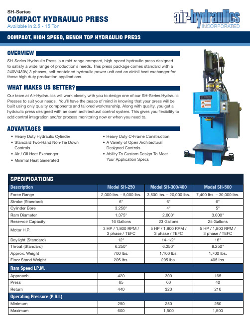
SH-SeriesCompaCt HydrauliC pressAvailable in 2.5 - 15 TonoverviewSH-Series Hydraulic Press is a mid-range compact, high-speed hydraulic press designed to satisfy a wide range of production’s needs. This press package comes standard with a 240V/480V, 3 phases, self-contained hydraulic power unit and an air/oil heat exchanger forthose high duty production applications.DescriptionModel SH-250Model SH-300/400Model SH-500Force Range 2,000 lbs. - 5,000 lbs.3,500 lbs. – 20,000 lbs.7,400 lbs. – 30,000 lbs.Stroke (Standard) 6" 6" 6" Cylinder Bore 3.250" 4" 5" Ram Diameter 1.375" 2.000" 3.000" Reservoir Capacity 16 Gallons 23 Gallons 25 Gallons Motor H.P. 3 HP / 1,800 RPM / 3 phase / TEFC5 HP / 1,800 RPM / 3 phase / TEFC5 HP / 1,800 RPM / 3 phase / TEFCDaylight (Standard) 12" 14-1/2" 16" Throat (Standard) 6.250" 6.250" 8.250" Approx. Weight 700 lbs. 1,100 lbs. 1,700 lbs. Floor Stand Weight205 lbs.205 lbs.405 lbs.Approach 420 300 165 Press 65 60 40 Return440320210Minimum 250 250 250 Maximum6001,5001,500wHat makes us Better?Our team at Air-Hydraulics will work closely with you to design one of our SH-Series Hydraulic Presses to suit your needs. You’ll have the peace of mind in knowing that your press will be built using only quality components and tailored workmanship. Along with quality, you get a hydraulic press designed with an open architectural control system. This gives you flexibility to add control integration and/or process monitoring now or when you need to.advantages• Heavy Duty Hydraulic Cylinder • Standard Two-Hand Non-Tie Down Controls• Air / Oil Heat Exchanger • Minimal Heat Generated• Heavy Duty C-Frame Construction • A Variety of Open Architectural Designed Controls• Ability To Custom Design To Meet Your Application SpecssH-series press dimensionssH-series Features & optionsOur objective is to offer you a solution to your assembly and forming needs. If our standard features or available options do not meet your application requirements, please consult our factory to see about us offering an affordable solution to meet your design needs.• “Opto-Touch” Control Buttons, Non-Tie Down Control Circuit • Rapid Ram Advance Using a Hi-Lo System• Anti-Rotation Ram Guide• 240V/480V, 3 Phase, Self-Contained Power Unit with HeatExchanger• Oil Level Gauge• Nema Enclosure• 120V Control Voltagestandard FeaturesavailaBle options• Matching Floor Stands• Pressure / Dwell / Distance Return Options• Adjustable Downstop• Jog Control Circuit• Fault Circuit Control Package (E-FI)• Increased Stroke Lengths• Press Frame Modifications• Other Voltage OptionsCustom designed options• Light Curtains & Guarding Packages• PLC Control Options• 4-Post and 2-Post Designs• Load Cell & Distance Monitoring Packages• Selectable Modes of Operation• Control Systems Designed for Future Expansion• Custom Tooling and Fixture Packages• Emergency Stop Control Circuit• 24vDC Control Circuit• Linear Position Transducer• Custom Control PackagesModel SH-500 15 TonS6" overall Stroke14.00" daylight opening 8.25" Throat depthsH-series Control paCkage optionsSH-Series Compact Hydraulic Press comes standard with basic two-hand non-tie down electric (110v) relay logic control package. Operator initiates and maintains both actuators at the same time to advance the press stroke. Once the operator releases one or both actuators, the ram returns to home position.Auto Ram Return options:(Add to the above standard control package)SH-PSTd: Pressure with Timer Return:Pressure sensor initiates an adjustable press dwell timer which returns the ram SH-PSdR: Distance ReturnAdjustable distance sensor initiates returns the ram SH-PSRR: Pressure Only Return:Pressure sensor only initiates the return of the ramSH-JCC: Jog Control CircuitOperator initiates and maintains both actuators at the same time to advance the press stroke. If the operator releases one of both actuators during the downward stroke, the ram stops downward motion. The operator can either proceed with the downward cycle by re-initiating the actuators until the auto ram return option is meet (see auto ram return options), or the operator can manually retract the ram to home position by pressing the manual ram return button (Note: includes SH-PSTD Pressure with Timer Return as the standard auto ram return option)other Available options:(please consult factory)• 24vDC Control Circuit • Programmable Logic Controller (PLC) • Emergency Stop Control Circuit • Light Curtains and Guarding • Rod End Load Cell • Linear Position Transducer • Press Force and Distance Monitoring • Custom Designed Control SystemsAir-Hydraulics is committed to delivering quality products on time to achieve customer satisfaction. Air-Hydraulics uses a process approach to achieve this policy in accordance with ISO 9001 and is committed to continually improve at this process.iso 9001 registered (witH design) **********************Phone: 1-800-837-4355Document No.: SH01Revision: Original。
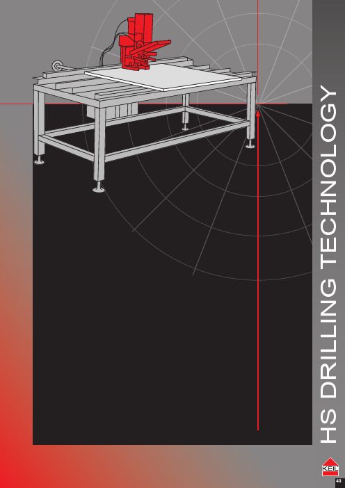
HS钻孔技术 43技术锚固件钻孔工具钻孔技术配件墙锚定器信息说明书
ANCHOR
FASTENERS
DRILLING TOOLS
Portable drilling machine KSHV Blow out nozzle for KSHV
532 Portable drilling machine KSHV
127 265
247
Execution
` Portable undercutting drilling machine with vacuum foot
33 ` Diamond tipped facade drill bit for through
holes 34 ` Roller conveyor drilling table KRT 47 ` Cooling water supply 62 ` Filter cartridge 62 ` Water pressure tank 63 ` Cooling lubricant 63 ` Fastener set 1 65 ` Whetstone 66 ` Wooden case for transportation of KSDV,
Portable drilling machine KRDV
` The portable drilling machines are used for professional mobile drilling and undercutting of small batches, infill and special size panels.
KSHV and KRDV 65 ` Seal for vacuum foot 66 ` Ball bearing 66 ` Carbon brush set 66 ` Cable integrated circuit breaker 67 ` Water locking 67 ` Silencer 67 ` Corrosion inhibitor 68
江钻钻头介绍及应用参数

一、牙轮钻头1、结构1)钻头的结构特点三牙轮钻头是由牙掌、牙轮、轴承、锁紧元件、储油密封系统、切削齿和流道喷嘴水力结构等二十多种零部件组成。
2、工作原理1)钻头的公转钻头的公转速度就是转盘或井下动力钻具的旋转速度。
钻头公转时,牙轮也绕钻头轴线旋转,牙轮上各排牙齿绕钻头轴线旋转的线速度不同,外排齿的线速度最大。
2)钻头的自转钻头旋转时,牙轮绕牙掌轴线作反时针旋转的运动叫自转。
牙轮的自转速度决定于钻头的公转转速,并与牙齿对井底的作用有关,是岩石对牙齿的吃入破碎作用产生阻力作用的结果。
3)钻头的纵振(轴向振动)冲击压碎作用轮心位置的变化使钻头沿轴向作上下往复运动,就是钻头的纵向振动,它与牙齿的齿高、齿距等钻头结构参数及岩性有关。
软地层振幅小,硬地层振幅大。
振动频率与齿数和牙轮转速成正比。
4)钻头的滑动剪切破碎作用破碎不同类型的岩石,要求钻头有不同的滑动量,滑动量由钻头结构参数决定。
软地层钻头滑动量大,硬地层应尽量小或不滑动。
3、江钻牙轮钻头表示方法江钻三牙轮钻头型号由四部分组成:钻头直径代号钻头系列代号钻头分类号钻头附加结构特征代号示例:8 1/2MD517X8 1/2:钻头直径8.5英寸(215.9mm)MD:高速马达钻头系列代号517:适合低抗压强度和高可钻性地层的镶齿钻头X:主切削齿为凸顶楔形齿1)钻头直径代号:用数字(整数或分数)表示,单位一般为英寸。
2)钻头系列代号:对于三牙轮钻头,按其适用功能、轴承及密封结构主要特征等方面,分为13个标准系列。
钻头应用表配套系统——轴承和性能3)三牙轮钻头分类号、江钻牙轮钻头与IADC编码对应表和钻头类型与地层级别对应关系表:分类号采用SPE/IADC 23937的规定,由三位数字组成,首位数为切削结构类别及地层系列号,第二位为地层分级号,末位数为钻头结构特征代号。
4)钻头附加结构特征代号:为了满足钻井及地层的某些特殊需要,钻头需改进或加强时,则在分类号后加附加结构特征。
- 1、下载文档前请自行甄别文档内容的完整性,平台不提供额外的编辑、内容补充、找答案等附加服务。
- 2、"仅部分预览"的文档,不可在线预览部分如存在完整性等问题,可反馈申请退款(可完整预览的文档不适用该条件!)。
- 3、如文档侵犯您的权益,请联系客服反馈,我们会尽快为您处理(人工客服工作时间:9:00-18:30)。
安全注意事项
警告!
在产品使用时,为避免出现安全事故隐患,请注意以下安全条例:
1.在使用本产品前仔细阅读操作说明书。
2.操作时,请穿戴工作服、安全眼镜、安全帽等;严禁穿戴松散的衣服和纱手套,以免发生危险。
3.在高空作业环境下,请确保机器固定并使用保险链再进行作业。
4.在潮湿或下雨天气作业时,请注意漏电安全防范。
5.禁止在易燃易爆区域内使用该产品。
6.如果钻头被卡住,请立即关闭电机。
7.更换、拆卸钻头前,必须在钻机电源插头末插上状态下进行。
8.禁止在钻头旋转时用手触摸。
参数表(回转速)适用HSS类:
使用说明书
二、加工范围:各种材质的钢板、钢管、铸铁、不锈钢、铝、铜及各种非金属材料上钻孔作
业。
三、切削条例:切削液内部冷却加工作业(内喷射型)。
四、操作说明:
1.安装方法,安装前请确认电源插头呈断开状,电机开关呈关闭状态。
根据选定的型号参照[安装示例图]所对应的安装图正确安装。
如图所示:
将合适的定位杆插入产品中心孔内※双扁柄如图1所示:将柄端两平面对准钻机主轴上的两喉噻顶丝孔。
用六角扳手拧紧并稍留0.2-0.3mm的空隙,用手轻轻来回转动确认位置准确后用力拧紧顶丝。
※通用柄如图2所示:将柄端小圆点对准主轴指示线往上推,待听到“咔嚓”声即可;※FEIN快速柄如图3所示:将主轴上保险环顺时针旋转到位,将柄端直接插入并小范围旋转直至发出“咔嚓”声即可。
2.定位,在需要钻孔的位置用中心錾打一定位点或用合金针划上“十”字线,以确保孔位置的精度。
注意,用中心錾打定位点时,中心錾必须确保垂直加工工件,以免影响切削料芯的顺利排出。
3.钻孔开始,调好合适的转速,开机前请确保钻机磁座底部干净,先打开磁座开关再打开电机开关,电机运转同时打开冷却液开关,慢慢进给直至切削稳定(深度大约1-2mm左右),再适当用力加速快进给速度,但不可用力过猛。
4.钻孔结束后,关闭电机开关待主轴停止转动后,用铁钩除去缠绕在本体上的铁屑,才可继续作业。
5.在钻孔工作时,如遇到以下情况应注意:
(1)排屑不通畅或铁屑呈粉末状,要检查是否铁屑缠绕过多影响排屑应及时清除,或检查产品切削刃是否磨损钝化应及时更换新的产品。
(2)如发生主轴停止转动,为避免损伤刀刃,请先关闭电机,逆方向回转1mm 左右后再回升电机。
(3)发现圆形料芯不能排出时,请用非金属棒避开刀刃轻轻敲打本体部直至料芯弹出。
(4)在对多重板材上进行钻孔时,每钻穿一层,要除去圆形料芯和缠绕铁屑后再进行工作。
(5)在难加工材料上作业,因产生热量过大,必须使产品充分冷却,从而延长产品使用寿命。
