3Com SuperStack 3 Switch4200系列交换机配置手册
3COM4228G中文配置手册

3C O M4228G中文配置手册work Information Technology Company.2020YEAR3Com SuperStack 3 Switch4200 系列交换机中文电子手抄本【文档说明】1.本文档为免费文档,请勿用作商业用途。
2.虽然作者企图避免错误的发生,但由于水平及理解能力的影响,文档中还是可能存在错误。
如果发现文档中的错误,请发邮件通知作者,作者的邮箱地址为: Aaron_Zhao@3.先在此向发现问题并通知作者的同仁表示严重感谢,希望大家多交流。
4.欢迎大家将此文档向外发送,发送时请勿对文档内容进行修改。
5.对于使用本文档中的内容,对交换机进行配置时可能引起的故障及错误,作者本人不负任何责任。
6.以上说明条款不具有强制性,目的是为了大家得到更好帮助信息。
对于不遵守以上条款的人,作者每日将鄙视之一至两次或更多。
[参考信息]1.3Com交换机软件及文档页面/products/en_US/downloadsindex.jsp?home1=supportdownloa d2.3Com Knowledgebase主页3.华为3Com热线电话 800-810-05044.3Com技术支持电话 800-810-3033SS3 4200交换机介绍SS3 4200系列交换机是3Com生产的一款可管理的二层交换机,该系列交换机目前包括三个型号,分别是4226T(3C17300)、4250T(3C17302)及4228G(3C17304)。
其中:●4226T 包括24个10Base-T/100Base-Tx自适应口,2个10Base-T/100Base-Tx/1000Base-T自适应口●4250T 包括48个10Base-T/100Base-Tx自适应口,2个10Base-T/100Base-Tx/1000Base-T自适应口●4228G 包括24个10Base-T/100Base-Tx自适应口,2个10Base-T/100Base-Tx/1000Base-T自适应口,2个GBIC口。
3Com_SuperStack_3_Switch4200系列交换机配置手册

3Com SuperStack 3 Switch4200 系列交换机中文电子手抄本【文档说明】1.本文档为免费文档,请勿用作商业用途。
2.虽然作者企图避免错误的发生,但由于水平及理解能力的影响,文档中还是可能存在错误。
如果发现文档中的错误,请发邮件通知作者,作者的邮箱地址为:**************************先在此向发现问题并通知作者的同仁表示严重感谢,希望大家多交流。
3.欢迎大家将此文档向外发送,发送时请勿对文档内容进行修改。
4.对于使用本文档中的内容,对交换机进行配置时可能引起的故障及错误,作者本人不负任何责任。
5.以上说明条款不具有强制性,目的是为了大家得到更好帮助信息。
对于不遵守以上条款的人,作者每日将鄙视之一至两次或更多。
[参考信息]1.3Com交换机软件及文档页面/products/en_US/downloadsindex.jsp?home1=supportdownload2.3Com Knowledgebase主页3.华为3Com热线电话 800-810-05044.3Com技术支持电话 800-810-3033SS3 4200交换机介绍SS3 4200系列交换机是3Com生产的一款可管理的二层交换机,该系列交换机目前包括三个型号,分别是4226T(3C17300)、4250T(3C17302)及4228G(3C17304)。
其中:●4226T 包括24个10Base-T/100Base-Tx自适应口,2个10Base-T/100Base-Tx/1000Base-T自适应口●4250T 包括48个10Base-T/100Base-Tx自适应口,2个10Base-T/100Base-Tx/1000Base-T自适应口●4228G 包括24个10Base-T/100Base-Tx自适应口,2个10Base-T/100Base-Tx/1000Base-T自适应口,2个GBIC口。
3Com StiperStack 3 Switch 4200调试方法探析

对 40 20交 换 机 端 口的 设 置 包 括 将 端 口 b c , 除 b c , l k解 o l k o
改 变 端 口 的 工 作 状 态 等 。 命 令 在 Sl t euotn (hs a e c m n p o pyi l e i c—
It* * *c/t re) 子 菜 单 下 。 下 面 举 例 列 出一 些 可 能 用 n e ee ent: h
3. 口设 置 端
是厂 商 给 出的 技 术 资 料 有 一 定 的 局 限 性 , 面 上 又 没 有 相 应 市
实用 的说 明资 料 , 人 通 过 反 复 实 验 , 出 了对 40 本 得 20系 列 基 本
功能 的调 试 方 法 , 以下 就 它 的 管 理 方 式 ( e e 、 o sl、 b基 T l tC no We n e
通 过 C no 对 交 换 机 进 行 管 理 是 最 基 本 的 一 种 方 式 , os e1 l3 也 是 最 后 一 种 管 理 方 式 , 其 他 管 理 方 式 都 不 能 进 入 交 换 机 当 时 , C no 用 osl 连 到 交 换 机 的 管 理 端 口试 一 试 。 如 果 通 过 e线 Cno osl e口都 不 能 进 入 交 换 机 , 说 明交 换 机 问 题 比较 严 重 , 那 有
A N D M
A R K ET
3 o t eSak3S i h4 0 C r Si rtc wt 2 0调 试 方 法 探 析 n p c
马敬祥
新疆 兵 团高等 专科 学校 鸟鲁木 齐 8 10 33 0
摘 要 : "前 校 园 网 的 维 护 和 应 用 中 ,20 系列 交换 机 属 于 主 流 产 品 , 是 , 商 给 出的 技 术 资料 有 一 定 的 局 限 在- 3 40 但 厂
H3C三层交换机安全配置规范
H3C三层交换机安全配置规范4.1管理平面安全配置4.1.1管理口防护4.1.1.1关闭未使用的管理口项目编号NOMD-2013-SC-H3C(L3SW)-01-01-01-v1配置说明设备应关闭未使用的管理口(AUX、或者没开启业务的端口)。
重要等级高配置指南1、参考配置操作#interface Ten-GigabitEthernet0/1 //进入端口视图shutdown //执行shutdown命令,关闭端口#检测方法及判定依据1、符合性判定依据端口关闭,不能使用。
2、参考检测方法通过网线或光纤(视具体接口不同),将此端口与PC或其他设备未关闭的端口互连,该端口指示灯灭,且PC或其他设备没有网卡UP的提示信息。
备注4.1.1.2配置console口密码保护项目编号NOMD-2013-SC-H3C(L3SW)-01-01-02-v1配置说明设备应配置console口密码保护重要等级高配置指南1、参考配置操作[H3C]user-interface console 0[ H3C-ui-console0] authentication-mode password[ H3C-ui-console0] set authentication password cipher xxxxxxxx检测方法及判定依据1、符合性判定依据通过console口,只有输入正确密码才能进入配置试图2、参考检测方法PC用Console线连接设备Console口,通过超级终端等配置软件,在进入设备配置视图时,提示要求输入密码。
备注4.1.2账号与口令4.1.2.1避免共享账号项目编号NOMD-2013-SC-H3C(L3SW)-01-02-01-v1配置说明应对不同的用户分配不同的账号,避免不同用户间账号共享。
重要等级中配置指南1、参考配置操作local-user user1service-type telnetuser privilede level 2#local-user user2service-type ftpuser privilede level 3#2、补充操作说明1、user1和user2是两个不同的账号名称,可根据不同用户,取不同的名称,建议使用:姓名的简写+手机号码;2、避免使用h3c、admin等简单易猜的账号名称;检测方法及判定依据1、符合性判定依据各账号都可以正常使用,不同用户有不同的账号。
常用2层交换机介绍及配置

3com交换机介绍及配置一、3com交换机介绍:我们常用的3com交换机型号为3824和3848,两款交换机的是最后4个电口和4个光口是不能复用的,也就是说如果最后4个电口被使用那么那4个光口就无法使用。
这个和H3C的交换机基本一样,但不同的是H3C的交换机最后4个光口是49、50、51、52口。
需要使用时需要进入交换机手动启用呗shuodown掉的49、50、51、52口。
咱们所使用的3com交换机的com口速率和Cisco交换机以及H3C交换机不同,速率为19200,而其他两个品牌的速率为9600.这里需要特别注意。
但是不是所有的3com 交换机的速率都是19200,万一碰到其他型号的请先去网上查一下!不过后期的设备基本上都会统一到9600的速率。
3com交换机的配置界面跟其他交换机也有些不同(让人很纠结的配置界面……)。
其他的交换机配置都是全命令式!而3com的配置则是目录式的。
各种不通的配置在不同的目录下,需要用命令进入相应的目录来进行配置。
3com交换机下“tab”键也有补全功能,但是用tab键补全的话会直接进入你所补全的目录下。
你可以一级目录敲一次命令,如果你记的比较熟了也可以把每级的目录用空格隔开,然后直接回车进入你想要去的最终目录。
3com交换机没有保存命令,配置好后会自动保存(根据NPB的前辈们的经验3com 交换机配置好后等半分钟,重启一下。
看看配置有没有丢在使用。
因为有可能会有配置完后断电配置全丢的可能)。
二、3com交换机的常用配置此次配置只涉及到交换机的初配和vlan、trunk的配置。
1,恢复密码:我们拿到交换机最有可能碰到的就是密码不对。
先确认交换机确实没有人使用了在进行此操作。
恢复方法如下:在输入用户名密码的时候用户名以及密码都使用recover。
稍等大约5秒左右,系统会提示你断电重启交换机。
并开始30秒倒计时。
重启后会提示你在次输入新密码,并确认新密码。
输入后使用默认的用户名admin 就可以登录了。
3COM三层交换机3226路由设置
3COM三层交换机3226路由设置3COM SuperStack#3 Switch 3226是一款三层交换机,它有24个10/100M自适应RJ45口,2个10/100/1000M RJ45口或光纤口和1个DB9-M控制台接口。
在端口的默认方式下,3226支持交叉线和直连线两种方式连接。
以下面的案例来说明该交换机的配置过程:一现场系统的网络结构为双网,网络地址段分别为:网段一(称为iese200net1):192.168.1.0,掩码255.255.255.0网段二(称为iese200net2):192.168.2.0,掩码255.255.255.0 现系统需与另一网段(称为ertunet网段)10.131.2.0内的程序通信,即系统的网段一和网段二都要与另一网段连通。
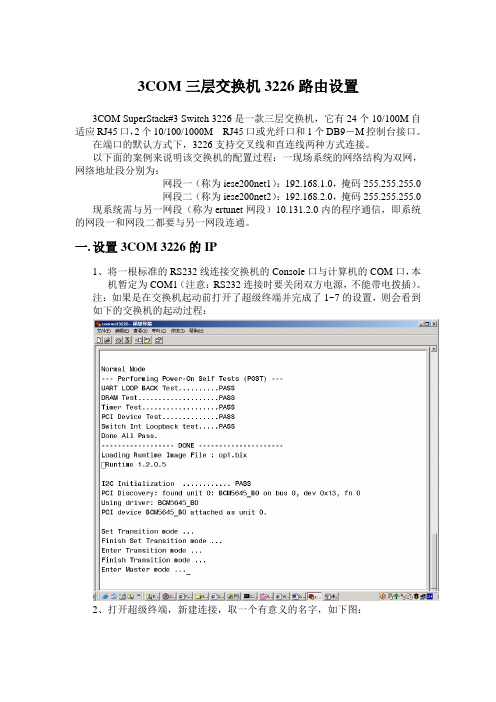
一.设置3COM 3226的IP1、将一根标准的RS232线连接交换机的Console口与计算机的COM口,本机暂定为COM1(注意:RS232连接时要关闭双方电源,不能带电拨插)。
注:如果是在交换机起动前打开了超级终端并完成了1~7的设置,则会看到如下的交换机的起动过程:2、打开超级终端,新建连接,取一个有意义的名字,如下图:3、按确定进入下一对话框4、选择COM1,按确定进入下一对话框在端口设置中一定要选择和交换机默认的数据格式。
3226要求的数据格式为:波特率:19200bp;数据位8;奇偶校验:无;停止位:1;数据流控制:无。
点击“确定”,进入主窗口。
5、选择“文件”、“属性”菜单6、点击“设置”属性框中的“ASCII码设置”框。
7、在出现的对话框中选中“以换行作为发送行末尾”复选框,按确定退出该对话框。
8、在超级终端的客户区按回车键,直至出现如下画面:9、在Login:提示符下输入Admin,回车。
初始密码为空,出现如下内容:interface summary(注:上述命令可单个输入后按回车键或全部输入后再按回车,即出现最后命令列表。
华为3COM交换机配置命令详解
华为3COM交换机配置命令详解1、配置文件相关命令[quidway]displaycurrent-configuration;显示当前生效的配置[quidway]displaysaved-configuration;显示flash中配置文件,即下次上电启动时所用的配置文件resetsaved-configuration;檫Bellary的配置文件reboot;交换机重新启动displayversion;表明系统版本信息2、基本布局[quidway]superpassword;修改特权用户密码[quidway]sysname;交换机命名[quidway]interfaceethernet0/1;步入USB视图[quidway]interfacevlanx;步入USB视图[quidway-vlan-interfacex]ipaddress10.65.1.1255.255.0.0;布局vlan的ip地址[quidway]iproute-static0.0.0.00.0.0.010.65.1.2;静态路由=网关3、telnet布局[quidway]user-interfacevty04;进入虚拟终端[s3026-ui-vty0-4]authentication-modepassword;设置口令模式[s3026-ui-vty0-4]setauthentication-modepasswordsimple222;设置口令[s3026-ui-vty0-4]userprivilegelevel3;用户级别4、端口配置[quidway-ethernet0/1]duplex{half|full|auto};布局端口工作状态[quidway-ethernet0/1]speed{10|100|auto};配置端口工作速率[quidway-ethernet0/1]flow-control;布局端口流控[quidway-ethernet0/1]mdi{across|auto|normal};布局端口平接扭接[quidway-ethernet0/1]portlink-type{trunk|access|hybrid};设置端口工作模式[quidway-ethernet0/1]undoshutdown;转化成端口[quidway-ethernet0/2]quit;选择退出系统视图5、链路生成布局[devicea]link-aggregationgroup1modemanual;创建手工聚合组1[devicea]interfaceethernet1/0/1;将以太网端口ethernet1/0/1重新加入生成组与1[devicea-ethernet1/0/1]portlink-aggregationgroup1[devicea-ethernet1/0/1]interfaceethernet1/0/2;将以太网端口ethernet1/0/1重新加入生成组与1[devicea-ethernet1/0/2]portlink-aggregationgroup1[devicea]link-aggregationgroup1service-typetunnel#在手工生成组的基础上建立tunnel业务Jaguaribe组与。
Juniper Networks EX 4200 系列交换机 说明书
ཥॴڦЪุӻ୕
EX 4200 系列交換器使用與 Juniper 路由器相同之 JUNOS 作業 系統軟體,以支援全球最大型且最複雜之網路運作。
Juniper 全系列產品均使用通用的作業系統,使其能夠一致地 部署並操作控制面板功能。為維持這樣的一致性,JUNOS 軟體 遵循極嚴謹的單一源碼開發流程、每季更新之單一釋出版本的 原則,並採用具高可用性之模組架構,以杜絕單一元件之錯誤 導致整體系統故障的情形。
PAocicnetss
West ClosetFloor N来自East Closet
Single Virtual Chassis System
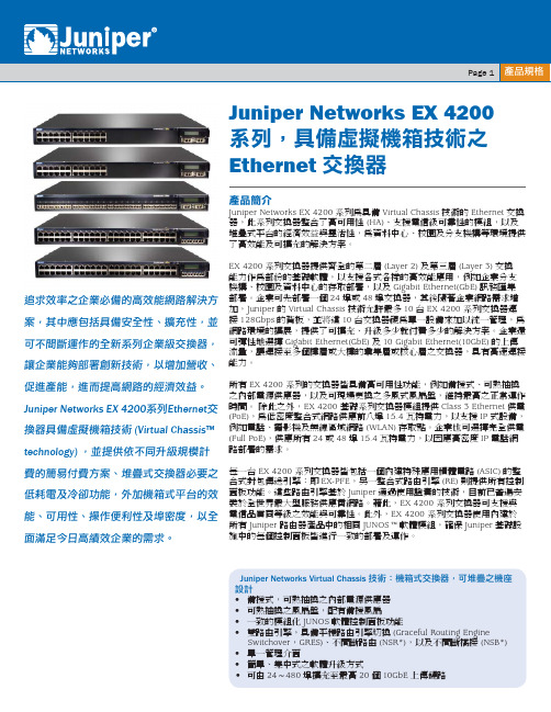
圖一:Virtual Chassis 技術允許最多 10 台 EX 4200 系列交換器相互 連接,以建立橫跨多個連線機櫃、樓層或甚至是多棟大樓的單一邏輯
交換器。
此外,專用的背板 RJ-45 連接埠可用來進行頻外管理,而前面 板 USB 連接埠可輕鬆上傳 JUNOS 軟體及設定檔。
Virtual Chassis Ҧஔ
利用 Virtual Chassis 技術,最多可將 10 台 EX 4200 系列交 換器相互連接,以建立單一邏輯交換器,可支援高達 480 個 10/100/1000BASE-T 埠或 240 個 100BASE-FX/1000BASE-X 埠, 再加上額外的 40 GbE 或 20 個 10GbE 上傳埠。不同機型可納 入同一個虛擬機箱交換器,以提供各種不同的 port 及密集度 選擇。
思科三层交换机配置总结

思科交换机的基本配置命令学习CISCO交换机基本配置:Console端口连接用户模式hostname# ;特权模式hostname(config)# ;全局配置模式hostname(config-if)# ;交换机口令设置:switch>enable ;进入特权模式switch#config terminal ;进入全局配置模式switch(config)#hostname csico ;设置交换机的主机名switch(config)#enable secret csico1 ;设置特权加密口令switch(config)#enable password csico8 ;设置特权非密口令switch(config)#line console 0 ;进入控制台口switch(config-line)#line vty 0 4 ;进入虚拟终端switch(config-line)#login ;虚拟终端允许登录switch(config-line)#password csico6 ;设置虚拟终端登录口令csico6switch#exit ;返回命令交换机VLAN创建,删除,端口属性的设置,配置trunk端口,将某端口加入vlan中,配置VTP:switch#vlan database ;进入VLAN设置switch(vlan)#vlan 2 ;建VLAN 2switch(vlan)#vlan 3 name vlan3 ;建VLAN 3并命名为vlan3switch(vlan)#no vlan 2 ;删vlan 2switch(config)#int f0/1 ;进入端口1switch(config)#speed ? 查看speed命令的子命令switch(config)#speed 100 设置该端口速率为100mb/s (10/auto)switch(config)#duplex ? 查看duplex的子命令switch(config)#duplex full 设置该端口为全双工(auto/half)switch(config)#description TO_PC1 这是该端口描述为TO_PC1switch(config-if)#switchport access vlan 2 ;当前端口加入vlan 2switch(config-if)#switchport mode trunk ;设置为trunk模式(access模式)switch(config-if)#switchport trunk allowed vlan 1,2 ;设置允许的vlanswitch(config-if)#switchport trunk encap dot1q ;设置vlan 中继switch(config)#vtp domain vtpserver ;设置vtp域名相同switch(config)#vtp password ;设置发vtp密码switch(config)#vtp server ;设置vtp服务器模式switch(config)#vtp client ;设置vtp客户机模式交换机设置IP地址,默认网关,域名,域名服务器,配置和查看MAC地址表:switch(config)#interface vlan 1 ;进入vlan 1switch(config-if)#ip address 192.168.1.1 255.255.255.0 ;设置IP地址switch(config)#ip default-gateway 192.168.1.6 ;设置默认网关switch(config)#ip domain-name 设置域名switch(config)#ip name-server 192.168.1.18 设置域名服务器switch(config)#mac-address-table? 查看mac-address-table的子命令switch(config)#mac-address-table aging-time 100 设置超时时间为100msswitch(config)#mac-address-table permanent 0000.0c01.bbcc f0/3 加入永久地址在f0/3端口switch(config)#mac-address-table restricted static 0000.0c02.bbcc f0/6 f0/7 加入静态地址目标端口f0/6源端口f0/7switch(config)#endswitch#show mac-address-table 查看整个MAC地址表switch#clear mac-address-table restricted static 清除限制性静态地址交换机显示命令:switch#write ;保存配置信息switch#show vtp ;查看vtp配置信息switch#show run ;查看当前配置信息switch#show vlan ;查看vlan配置信息switch#show interface ;查看端口信息switch#show int f0/0 ;查看指定端口信息switch#show int f0/0 status;查看指定端口状态switch#dir flash: ;查看闪存Cisco路由器配置命令大全网络 2010-06-26 06:43:44 阅读657 评论0 字号:大中小订阅 .(1)模式转换命令用户模式----特权模式,使用命令"enable"特权模式----全局配置模式,使用命令"config t"全局配置模式----接口模式,使用命令"interface+接口类型+接口号"全局配置模式----线控模式,使用命令"line+接口类型+接口号"注:用户模式:查看初始化的信息.特权模式:查看所有信息、调试、保存配置信息全局模式:配置所有信息、针对整个路由器或交换机的所有接口接口模式:针对某一个接口的配置线控模式:对路由器进行控制的接口配置(2)配置命令show running config 显示所有的配置show versin 显示版本号和寄存器值shut down 关闭接口no shutdown 打开接口ip add +ip地址配置IP地址secondary+IP地址为接口配置第二个IP地址show interface+接口类型+接口号查看接口管理性show controllers interface 查看接口是否有DCE电缆show history 查看历史记录show terminal 查看终端记录大小hostname+主机名配置路由器或交换机的标识config memory 修改保存在NVRAM中的启动配置exec timeout 0 0 设置控制台会话超时为0service password-encryptin 手工加密所有密码enable password +密码配置明文密码ena sec +密码配置密文密码line vty 0 4/15 进入telnet接口password +密码配置telnet密码line aux 0 进入AUX接口password +密码配置密码line con 0 进入CON接口password +密码配置密码bandwidth+数字配置带宽no ip address 删除已配置的IP地址show startup config 查看NVRAM中的配置信息copy run-config atartup config 保存信息到NVRAMwrite 保存信息到NVRAMerase startup-config 清除NVRAM中的配置信息show ip interface brief 查看接口的谪要信息banner motd # +信息 + # 配置路由器或交换机的描素信息description+信息配置接口听描素信息vlan database 进入VLAN数据库模式vlan +vlan号+ 名称创建VLANswitchport access vlan +vlan号为VLAN为配接口interface vlan +vlan号进入VLAN接口模式ip add +ip地址为VLAN配置管理IP地址vtp+service/tracsparent/client 配置SW的VTP工作模式vtp +domain+域名配置SW的VTP域名vtp +password +密码配置SW的密码switchport mode trunk 启用中继no vlan +vlan号删除VLANshow spamming-tree vlan +vlan号查看VLA怕生成树议2. 路由器配置命令ip route+非直连网段+子网掩码+下一跳地址配置静态/默认路由show ip route 查看路由表show protocols 显示出所有的被动路由协议和接口上哪些协议被设置show ip protocols 显示了被配置在路由器上的路由选择协议,同时给出了在路由选择协议中使用的定时器等信息router rip 激活RIP协议network +直连网段发布直连网段interface lookback 0 激活逻辑接口passive-interface +接口类型+接口号配置接口为被动模式debug ip +协议动态查看路由更新信息undebug all 关闭所有DEBUG信息router eigrp +as号激活EIGRP路由协议network +网段+子网掩码发布直连网段show ip eigrp neighbors 查看邻居表show ip eigrp topology 查看拓扑表show ip eigrp traffic 查看发送包数量router ospf +process-ID 激活OSPF协议network+直连网段+area+区域号发布直连网段show ip ospf 显示OSPF的进程号和ROUTER-IDencapsulation+封装格式更改封装格式no ip admain-lookup 关闭路由器的域名查找ip routing 在三层交换机上启用路由功能show user 查看SW的在线用户clear line +线路号清除线路3. 三层交换机配置命令配置一组二层端口configure terminal 进入配置状态nterface range {port-range} 进入组配置状态配置三层端口configure terminal 进入配置状态interface {{fastethernet | gigabitethernet} interface-id} | {vlan vlan-id} | {port-channel port-channel-number} 进入端口配置状态no switchport 把物理端口变成三层口ip address ip_address subnet_mask 配置IP地址和掩码no shutdown 激活端口例:Switch(config)# interface gigabitethernet0/2Switch(config-if)# no switchportSwitch(config-if)# ip address 192.20.135.21 255.255.255.0Switch(config-if)# no shutdown配置VLANconfigure terminal 进入配置状态vlan vlan-id 输入一个VLAN号, 然后进入vlan配态,可以输入一个新的VLAN号或旧的来进行修改。
S4200万兆汇聚型交换机_产品资料
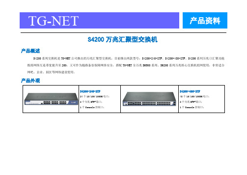
TG-NET 产品资料S4200万兆汇聚型交换机产品概述S4200系列交换机是TG-NET公司推出的万兆汇聚型交换机,目前推出两款型号:S4200-24G-2TF、S4200-48G-2TF。
S4200系列万兆口汇聚功能既将网络互连带宽提升至20G,又可作为链路备份保障网络安全,搭配TG-NET全万兆S6500系列、S6200系列万兆核心交换机组网使用,非常适合网吧、企业、园区等网络建设使用。
产品外观产品特点⏹无阻塞高速转发针对万兆网络大流量数据无阻塞的要求,S4200-24G-2TF提供88Gbps交换容量,全线速过滤转发66Mpps;S4200-48G-2TF提供136Gbps交换容量,全线速过滤转发102Mpps,保证所有端口的无阻塞的数据转发。
⏹完备的可靠性保护机制支持万兆口汇聚功能:链路汇聚,提升网络带宽;链路备份,保障网络安全;支持基于端口的用户IP+MAC地址认证;支持CPU保护策略,对上送CPU的报文进行流分类和流限速,避免非法攻击报文对CPU的攻击和资源消耗;支持风暴控制功能,可对单播、广播、未知单播报文进行风暴抑制;采用电信级的开关电源,具有防雷设计、防过压设计、防浪涌设计,电压可适应110~240V大范围,保证在不良自然天气及电压不稳环境下网络的正常运行;⏹制便捷的管理维护通过简单的可视化WEB界面,可对交换机的各种功能进行简单方便的操作;支持Reset按钮一键恢复出厂设置;支持端口短接恢复出厂设置,使维护更加简单;支持TGCP云平台统一管理,创新的360式网络诊断;⏹全新节能设计,引领低碳通信遵循IEEE 802.3az(Energy Efficient Ethernet 能效以太网),提供端口低耗电闲置模式,根据线缆长度进行相应输出功率调整,并且支持无连接时端口休眠,大幅度降低功耗。
Page 2 of 7 400-088-7500产品规格 Page 3 of 7 400-088-7500业务特性 Page 4 of 7 400-088-7500 Page 5 of 7 400-088-7500订购信息 Page 6 of 7 400-088-7500 Page 7 of 7 400-088-7500。
3com交换机扩展WAN配置教程

Type "quit" to return to the previous menu or ? for help
----------------------------------------- (1)---------------------------
Select menu option (bridge/vlan): cr
Select VLAN ID (2-4094)[3]: 3
Enter VLAN Name [VLAN 3]: vlan 3
nvram set wan15_ifname="eth1.16"
nvram set wan16_ifname="eth1.17"
nvram set wan17_ifname="eth1.18"
nvram set wan18_ifname="eth1.19"
nvram set wan19_ifname="eth1.20"
create - Create a VLAN
delete - Delete a VLAN
detail - Display detailed information
bridge - Administer bridge-wide parameters
gettingStarted - Basic device configuration
modify - Modify a VLAN
summary - Display summary information
Select menu option (bridge/vlan): cr
如何配置三层交换机的详细方法

如何配置三层交换机的详细方法配置三层交换机我们可以通过第三方软件来配置?具体配置方法是怎样呢?下面由店铺为你整理了如何配置三层交换机的相关方法,希望对你有帮助!配置三层交换机的方法步骤如下下载好pack软件后解压,如下图:解压后,安装pack(安装步骤省略),并运行,如下图:进入界面后,建立如下图所示(选择虚拟线:三条直通线,一条交叉线。
选择的虚拟pc:三台。
选择的虚拟交换机:二层交换机一个,三层交换机一个):进入二层交换机的CLI,配置成如下的参数(SW1>enSW1#conf tSW1(config)#interface FastEthernet0/1SW1(config-if)#switchport access vlan 10SW1(config)#interface FastEthernet0/2SW1(config-if)#switchport access vlan 20SW1(config)#interface FastEthernet0/3SW1(config-if)#switchport access vlan 30SW1(config-if)#do wrSW1(config-if)#exitSW1(config)#interface FastEthernet0/24SW1(config-if)#switchport mode trunkSW1(config-if)#exit验证结果:(最后要记得保存)SW1(config)#do show run如下图:)进入三层交换机的CLI,配置成如下的参数(Switch>Switch>enSwitch#Switch#conf tEnter configuration commands, one per line. End with CNTL/Z.Switch(config)#interface FastEthernet0/1Switch(config-if)#switchport trunk encapsulation dot1qSwitch(config-if)#switchport mode trunkSwitch(config)#interface Vlan10Switch(config-if)# ip address 192.168.1.1 255.255.255.0Switch(config)#interface Vlan20Switch(config-if)# ip address 192.168.2.1 255.255.255.0Switch(config)#interface Vlan30Switch(config-if)# ip address 192.168.3.1 255.255.255.0验证结果:(最后要记得保存)Switch#show#show run如下图:)用其中PC机,验证结果:即ping通全网,如下图:。
3COM-简明手册
3com配置快速入门手册3com 服务电话800-810-30333COM产品常见问题手册(内容包括如何软件升级,软件下载,TFTP下载,CONSOLE线缆图等):第一部分3Com交换机基本配置命令1. 1.3Com Switch 4300/4400/4900基本配置●●管理IP设定protocol/ip/basicconfig●●设定端口状态physicalinterface/Ethernet●●恢复出厂值system/control/initialize●●热启动system/control/reboot●●软件升级system/control/software upgrade●●Web管理在IE地址栏中输入管理IP即可(注:终端IP与管理IP需在同一个网段上)2. 2.3Com Switch 3300/1100基本配置●●管理IP设定ip/interface/define●●恢复出厂值system/initialize●●设定端口状态Ethernet●●软件升级system/software upgrade●●Web管理在IE地址栏中输入管理IP即可(注:终端IP与管理IP需在同一个网段上)3. 3.3Com Switch 4200基本配置●●管理IP设定protocol/ip/interface/modify●●恢复出厂值system/control/initialize4. 4.3Com Switch 4007基本配置●●管理IP设定set ip ip_address 192.168.2.1 ethernet_portset ip subnet_mask 255.255.255.0 ethernet_port●●恢复出厂值(需逐个模块恢复)connect 3.1(模块槽位)/module/nvdata/reset/y●●模块后置端口设置connect 7.1(交换引擎槽位)/bridge/trunk/automap/enable●●Web管理在IE地址栏中输入管理IP即可(注:终端IP与管理IP需在同一个网段上)第二部分模拟环境配置案例1. 1.设备准备2. 2.实现功能介绍最终实现VLAN1-----VLAN6之间可以相互访问,VLAN7可以访问VLAN1-----VLAN6,而VLAN1-----VLAN6不能访问VLAN7。
3Com 4200系列Switch介绍及设定

7
WKS 網絡組技術資料
端口设置
对4200交换机端口的设置包括将端口block,解除block,改变端口的工作状态等.命 令在Select menu option (physicalInterface/ethernet): 子菜单下.下面举例列出一些可能用 到的设置:
将端口1到 阻塞 阻塞,端口block后,端口的状态灯会在绿/黄之间交互闪烁, 将端口 到10阻塞 Select menu option (physicalInterface/ethernet): portstate This operation may take a number of seconds Select Ethernet ports (unit:port...,?): 1:1-1:10 Enter new value (enable,disable)[enable]: dis 改变端口2到 的自协商方式 改变端口 到5的自协商方式 Select menu option (physicalInterface/ethernet): portmode This operation may take a number of seconds Select Ethernet ports (unit:port...,?): 1:2-5 Enter auto-negotiation mode (enable,disable)[disable]: en Enter fallback port mode (10half,10full,100half,100full)[10half]: 10full [说明] 端口默认情况下auto-negotiation方式是enable的。Fallback port mode是指当端口自协商方式 失败时,最后到那个工作速率如果要指定端口的工作速率及全双工模式,需要将autonegotiation关闭,再设置速率及双工模式.
NETGEAR ProSAFE Managed Switches M4200 系列安装指南说明书
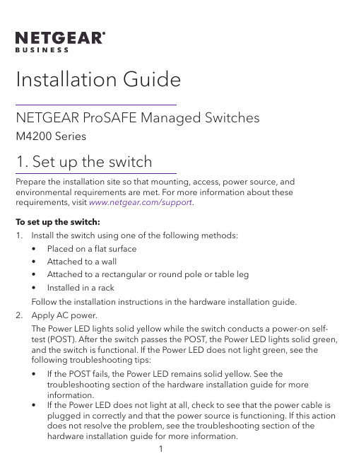
Installation GuideNETGEAR ProSAFE Managed SwitchesM4200 Series1. Set up the switchPrepare the installation site so that mounting, access, power source, and environmental requirements are met. For more information about these requirements, visit /support.To set up the switch:1. Install the switch using one of the following methods:• Placed on a flat surface• Attached to a wall• Attached to a rectangular or round pole or table leg• Installed in a rackFollow the installation instructions in the hardware installation guide.2. Apply AC power.The Power LED lights solid yellow while the switch conducts a power-on self-test (POST). After the switch passes the POST, the Power LED lights solid green, and the switch is functional. If the Power LED does not light green, see thefollowing troubleshooting tips:• If the POST fails, the Power LED remains solid yellow. See thetroubleshooting section of the hardware installation guide for moreinformation.• If the Power LED does not light at all, check to see that the power cable is plugged in correctly and that the power source is functioning. If this actiondoes not resolve the problem, see the troubleshooting section of thehardware installation guide for more information.3. Connect devices to the switch.We recommend using the following cables and SFP modules:• Use a Category 5e (Cat 5e), Category 6 (Cat 6), or Category 6a (Cat 6a) cable a for copper port at 1/2.5/5 Gbps.• Use a NETGEAR AGM731F or AGM732F for a fiber port at 1 Gbps.• Use a NETGEAR AXM761, AXM762, or AXM764 for a fiber port at 10 Gpbs.• Use a NETGEAR AXC761 (1 m) or AXC763 (3 m) cable for a fiber port. Note: If purchased, SFP modules and cables are shipped separately. For more information about installing an SFP module, see the hardware installation guide.2. Configure the IP address of the switchYou can access the switch through the out-of-band (OOB) port (which is also referred to as the service port) through a console port, or through any Ethernet network port. By default, the switch functions as a DHCP client.To configure the IP address of the switch, use one of the following methods:• Local browser–based management interface. Use the local browser interface through the OOB port or any Ethernet network port (see Use the local browser interface to configure the IP address).• CLI. Use the command-line interface (CLI) through the mini USB console port or RJ-45 RS232 console port. You can configure the IP address manually or use the ezconfig utility (see Use the CLI to configure the IP address).• DHCP server. Connect a DHCP server through the OOB port or through any Ethernet network port and find the assigned IP address (see Find the IP address assigned by the DHCP server).After you configure or find the IP address of the switch, you can configure the features of the switch through either the local browser interface or the CLI.Use the local browser interface to configure the IP address Y ou can use a computer on the same subnet as the switch to access the local browser interface over the switch’s default IP address and assign a different static IP address to the switch.1. Configure your computer with a static IP address:• For access over an Ethernet network port, use an IP address in the 169.254.0.0/16 subnet. For example, use 169.254.100.201.• For access over the OOB port, use an IP address in the 192.168.0.0/16 subnet. For example, use 192.168.0.100.2. Connect an Ethernet cable from an Ethernet port on your computer to anEthernet network port on the switch or to the OOB port on the switch.3. Launch a web browser and enter the default IP address of the switch in theaddress field of the browser:• For access over an Ethernet network port, enter 169.254.100.100.• For access over the OOB port, enter 192.168.0.239.A login window displays.4. Enter admin for the user name, leave the password field blank, and click theLOGIN button.The System Information page displays.5. S elect System > Management > Initial Setup.6. Configure the IP address settings of the management interface and OOB port.7. Click the Apply button.Your setting are saved.For information about using the local browser interface, see the user manual, which you can download by visiting /support/download/.Use the CLI to configure the IP addressTo use the CLI for initial configuration and assign a static or dynamic IP addressto the switch, connect a computer or VT100/ANSI terminal to one of the console ports on the switch.1. Depending on the connector type at your computer or terminal, and the portthat you are using on the switch, use one of the following cables, both of which are included in the product package:• USB console cable for use with the mini USB console port.Note: To use the mini USB port, you must install the USB driver on thecomputer. You can download the driver by visiting/support/download/.• Console cable for use with the RJ-45 RS232 console port.2. Connect one end of the cable to the appropriate port on the switch andconnect the other end to your computer or terminal.3. If you connect a computer to a console port on the switch, start a terminalemulation program:• On a computer with a Windows operating system, you can use HyperTerminal or Tera Term.• On a computer with a Mac operating system, you can use ZTerm.• On a computer with a Linux operating system, you can use TIP.4. If you connect a computer to a console port on the switch, configure theterminal emulation program to use the following settings: baud rate,115,200 bps; data bits, 8; parity, none; stop bit, 1; flow control, none.5. At the user prompt, log in to the switch using the user name admin and pressEnter. At the password prompt, do not type a password but press Enter.You can now use the CLI to manually configure the IP address of the switch, or to use the ezconfig utility, continue with the next step.Note: For information about CLI management, see the CLI reference manual.6. At the next command prompt, type ezconfig and press Enter.The ezconfig utility is now running on the switch.Netgear Switch) #ezconfigEZ Configuration Utility7. Using ezconfig, set up the basic switch configuration, including a static IPaddress and subnet mask.8. Use the switch IP address that is assigned by ezconfig to log in to the switch’slocal browser interface.Find the IP address assigned by the DHCP serverBy default, the switch functions as a DHCP client and gets its IP address froma DHCP server in the network. To find the assigned IP address of the switch’s management interface or OOB port, connect a computer or VT100/ANSI terminal to one of the console ports on the switch.1. Make sure that the switch is connected to a DHCP server.2. Set up a console connection with the switch.For information about setting up a console connection, see Steps 1 through 5 in Use the CLI to configure the IP address. After you are logged in and at the CLI command prompt, continue with the next step.3. At the command prompt, type one of the following commands:• To find the IP address of the management interface, type theshow ip management command, and press Enter.• To find the IP address of the OOB port (which is also referred to as the service port), type the show serviceport command, and press Enter.The active IP address displays.4. Use either the management interface IP address or the OOB port IP address tolog in to the switch’s local browser interface.3. Log In to the web management interfaceManage the features of your switch through the web management interface with the appropriate IP address for your configuration.To log in to the switch’s web management interface:1. Enter http://<ipaddress> in the web browser address field.A login window displays.2. Enter admin for the user name, leave the password field blank, and click theLOGIN button.The System Information page displays. You can now navigate from this page to other pages and configure your switch.For information about using the web management interface, visithttps:///support to download the software setup manual and the user manual.安装指南NETGEAR ProSAFE 网管交换机M4200 系列1. 安装交换机准备一处符合安装、接入、电源和环境要求的安装位置。
Dell EMC PowerSwitch S4200-ON系列设置指南说明书
Dell EMC PowerSwitch S4200-ON Series Set-up GuideNotes, cautions, and warningsA NOTE indicates important information that helps you make better use of your product.A CAUTION indicates either potential damage to hardware or loss of data and tells you how to avoidA WARNING indicates a potential for property damage, personal injury, or death.Copyright © 2017 Dell Inc. or its subsidiaries. All rights reserved. Dell, EMC, and other trademarks are trademarks of Dell Inc. or its subsidiaries. Other trademarks may be trademarks of their respective owners.Chapter 1: About this guide (4)Related documents (4)Information Symbols (4)Chapter 2: Site preparations (6)Site selection (6)Cabinet placement (6)Rack mounting (7)Switch ground (7)Fans and airflow (7)Power (7)Storing components (7)Chapter 3: S4200-ON Series Installation (8)Unpack (8)Rack or cabinet installation (9)ReadyRails installation (9)1U Tool-less mount installation (10)Two-post flush-mount installation (11)Two-post center-mount installation (12)Four-post threaded installation (13)S4200-ON Series switch installation (14)1U front-rack installation (14)Optics installation (16)Switch power-up (16)After switch installation (16)Chapter 4: Specifications (17)Chassis physical design (17)Chapter 5: Support (19)Contents3About this guideThis guide provides site preparation recommendations, step-by-step procedures for rack mounting and desk mounting, inserting modules, and connecting to a power source.To avoid electrostatic discharge (ESD) damage, wear grounding wrist straps when handling thisOnly trained and qualified personnel can install this equipment. Read this guide before you install and power up thisThis equipment contains optical transceivers, which comply with the limits of Class 1 laser radiation.When no cable is connected, visible and invisible laser radiation may be emitted from the aperture of the optical Topics:•Related documents •Information SymbolsRelated documentsFor more information about the S4200-ON Series (S4248FB-ON and S4248FBL-ON), see the following documents.●OS10 Enterprise Edition Release Notes●OS10 Enterprise Edition User Guide●S4200-ON Series Installation Guide●Dell Open Networking Hardware Diagnostic GuideFor the most recent documentation, visit the support site: /support.Information SymbolsThe Note icon signals important operational information.The Caution icon signals information about situations that could result in equipment damage or loss The Warning icon signals information about hardware handling that could result in injury.14About this guideThe ESD Warning icon requires that you take electrostatic precautions when handling the device.About this guide52Site preparationsThe S4200-ON Series (S4248FB-ON and S4248FBL-ON) is suitable for installation as part of a common bond network (CBN).You can install the switch in:●Network telecommunication facilities●Data centers●Other locations where the National Electric Code (NEC) appliesFor more information about the S4200-ON Series specifications, see Specifications.Topics:•Site selection•Cabinet placement•Rack mounting•Switch ground•Fans and airflow•Power•Storing componentsSite selectionInstall your equipment in restricted access areas. A restricted access area is one where service personnel can only gain access using a special tool, lock, key, or other means of security. The authority responsible for the location controls access to the restricted area.Ensure that the area where you install your switch meets the following safety requirements:●Near an adequate power source. Connect the switch to the appropriate branch circuit protection according to your localelectrical codes.●Environmental—switch location—continuous temperature range is from 0°C to 45°C (32°F to 113°F).●Operating humidity is from 5 to 85 percent noncondensing, continuous.●In a dry, clean, well-ventilated, and temperature-controlled room, away from heat sources such as hot cooling vents or directsunlight.●Away from sources of severe electromagnetic noise.●Positioned in a rack or cabinet, or on a desktop with adequate space in the front, back, and sides for proper ventilation andaccess.●Install the switch in Information Technology Rooms in accordance with Article 645 of the National Electrical Code and NFPA75.For more information about switch storage and environmental temperatures, see Specifications.Cabinet placementInstall the S4200-ON Series (S4248FB-ON and S4248FBL-ON) switch only in indoor cabinets designed for use in a controlled environment.Do not install the switch in outside cabinets. For cabinet placement requirements, see Site selection.The cabinet must meet minimum size requirements. Airflow must be in accordance with the Electronic Industries Alliance (EIA) standard. Ensure that there is a minimum of 5 inches (12.7 cm) between the intake and exhaust vents and the cabinet wall.6Site preparationsRack mountingWhen you prepare your equipment rack, ensure that the rack is grounded. Ground the equipment rack to the same ground point the power service in your area uses. The ground path must be permanent.Switch groundDell EMC recommends grounding your switch. Use the S4200-ON Series switch in a CBN.Fans and airflowFan installation is done as part of the factory install based on stock keeping unit (SKU) type. The S4200-ON Series has SKUs that support the following configurations:●AC PSU with fan airflow from the I/O to the PSU—normal●AC PSU with fan airflow from the PSU to the I/O—reverse●DC fan unit with airflow from the I/O to the PSU—normal●DC fan unit with fan airflow from the PSU to the I/O—reverseBe sure to order the fans suitable to support your site’s ventilation. Use a single type of airflow fan in your switch. Do not mix reverse and normal airflows in a single switch.For proper ventilation, position the switch in an equipment rack or cabinet with a minimum of 5 inches (12.7 cm) of clearance around the exhaust vents. The fan speed varies based on internal temperature monitoring. The switch never intentionally turns off the fans.PowerTo connect the switch to the applicable power source, use the appropriate power cable. An AC power cable is included with the switch.When installing AC or DC switches, follow the requirements of the National Electrical Code ANSI/NFPA 70, where applicable. The switch is powered-up when the power cable is connected between the switch and the power source.Always disconnect the power cable before you service the power supply slots. The switch hasOn the AC switch, use the power supply cable as the main disconnect device. Ensure that theModule power is software controlled. You do not see module LEDs when the switch powers up in ONIE.Storing componentsIf you do not install your S4200-ON Series switch and components immediately, properly store the switch and all optional components following these guidelines:●Storage location temperature must remain constant. The storage range is from -40°C to 70°C (-40°F to 158°F).●Store on a dry surface or floor, away from direct sunlight, heat, and air conditioning ducts.●Store in a dust-free environment.ESD damage can occur when components are mishandled. Always wear an ESD-preventive wrist or heel groundSite preparations7S4200-ON Series InstallationTo install the S4200-ON Series (S4248FB-ON and S4248FBL-ON), complete the installation procedures in the order presented in this section.ESD damage can occur if components are mishandled. Always wear an ESD-preventive wrist or heel ground strap Topics:•Unpack •Rack or cabinet installation •ReadyRails installation •1U Tool-less mount installation •Two-post flush-mount installation •Two-post center-mount installation •Four-post threaded installation •S4200-ON Series switch installation •1U front-rack installation •Optics installation •Switch power-up •After switch installationUnpackBefore unpacking the switch, inspect the container and immediately report any evidence of damage.When unpacking the S4200-ON Series switch, make sure that the following items are included:●One S4200-ON Series (S4248FB-ON or S4248FBL-ON) switch ●One RJ-45 to DB-9 female cable ●Two sets of rail kits, no tools required ●Two PSUs ●Five fan units ●Two country- and region-specific AC power cords ●S4200-ON Series Set-up Guide ●Safety and Regulatory Information ●Warranty and Support Information 1.Place the container on a clean, flat surface and cut all straps securing the container.2.Open the container or remove the container top.3.Carefully remove the switch from the container and place it on a secure and clean surface.4.Remove all packing material.5.Inspect the product and accessories for damage.38S4200-ON Series InstallationRack or cabinet installationYou may either place the switch on a rack shelf or mount the switch directly into a 19" wide, EIA-310- E-compliant rack.Rack mounting includes four-post, two-post, round threaded holes, or square holes. The ReadyRails system is provided for 1U front-rack and two-post installations.The ReadyRails system includes two separately packaged rail assemblies. To begin installation, separate each rail assembly by sliding the inside rail out of the outside rail.This guide is a condensed reference. Read the safety instructions in your Safety, Environmental, andinformation booklet before you begin.The illustrations in this section are not intended to represent a specific switch.Do not the use the mounted ReadyRails as a shelf or a workplace.Rack mount safety considerations●Rack loading—Overloading or uneven loading of racks may result in shelf or rack failure, possibly damaging the equipmentand causing personal injury. Stabilize racks in a permanent location before loading begins. Mount the components starting at the bottom of the rack, then work to the top. Do not exceed your rack’s load rating.●Power considerations—Connect only to the power source specified on the unit. When you install multiple electricalcomponents in a rack, ensure that the total component power ratings do not exceed the circuit capabilities. Overloaded power sources and extension cords present fire and shock hazards.●Elevated ambient temperature—If you install the switch in a closed rack assembly, the operating temperature of the rackenvironment may be greater than the room ambient temperature. Use care not to exceed the 45°C maximum ambient temperature of the switch.●Reduced air flow—Do not compromise the amount of airflow required for safe operation of the equipment. Install theequipment in the rack so that the equipment constantly has the correct amount of airflow surrounding it.●Reliable earthing—Maintain reliable earthing of rack-mounted equipment. Pay particular attention to the supply connectionsother than the direct connections to the branch circuit, for example: use of power strips.●Do not mount the equipment with the fan panel facing in the downward position.ReadyRails installationTo easily configure your rack for switch installation, use the ReadyRails rack mounting system provided.You can install the ReadyRails system using the 1U tool-less square-hole method or one of three possible 1U threaded round-hole methods. The tooled installation methods include two-post flush mount, two-post center mount, or four-post threaded mount. To begin installation, separate each rail assembly by sliding the inside rail out of the outside rail.For more installation instructions, see the installation labels attached to the rail assembly.S4200-ON Series Installation91U Tool-less mount installation1.Face the ReadyRails flange ears facing outward. Place one rail between the left and right vertical posts. Align and seat theback flange rail pegs in the back vertical post flange.The center extractions show how the pegs appear in both the square and nonthreaded round holes.10S4200-ON Series InstallationFigure 3. 1U tool-less installation2.Align and seat the front flange pegs in the holes on the front side of the vertical post.Be sure that the rails click into place and are secure.3.Repeat this procedure for the second rail.4.To remove each rail, pull on the latch release button on each flange ear and unseat each rail.Two-post flush-mount installationFor more installation instructions, see the installation labels attached to the rail assembly.1.For this configuration, remove the latch castings from the front side of each ReadyRails assembly, item 1.To remove the two screws from each front flange ear on the switch side of the rail and remove each latch casting, usea Torx screwdriver. Retain the latch castings for future rack requirements. It is not necessary to remove the back flangecastings.S4200-ON Series Installation11Figure 4. Two-post flush-mount installation2.Attach one rail to the front post flange with two user-supplied screws, item 2.3.Slide the plunger bracket forward against the vertical post and secure the plunger bracket to the post flange with twouser-supplied screws, item 3.4.Repeat this procedure for the second rail.Two-post center-mount installation1.Slide the plunger bracket rearward until it clicks into place and secure the bracket to the front post flange with twouser-supplied screws, item 1.12S4200-ON Series InstallationFigure 5. Two-post center-mount installation2.Slide the back bracket towards the post. Secure it to the post flange with two user-supplied screws, items 2 and3.3.Repeat this procedure for the second rail.Four-post threaded installation1.Remove the latch castings from each end of the ReadyRails assemblies. To remove the two screws each latch casting, use aTorx driver.Retain the latch castings for future rack requirements.S4200-ON Series Installation13Figure 6. Four-post threaded installation2.For each rail, attach the front and back flanges to the post flanges with two user-supplied screws at each end.S4200-ON Series switch installationFor the 1U two-post configurations, slide the switch into the rails in the same manner as the four-post configurations.1U front-rack installationConfigure the rails that are attached to the switch.1. For more information, see the installation instruction labels on the rail.Attach the inner switch rails to the S4200-ON Series switch.Line up the rail with the mounting heads and attach the rail to the chassis. Slide the rail back until it locks into place. The following shows the detail of the front standoff with the locking tab:14S4200-ON Series InstallationFigure 7. Switch rail attachment2.After you install both rails, line them up on the ReadyRails. Slide the switch in until it is flush with the front of rack.About three inches before you fully insert your switch, the rail locking feature engages to keep the switch from inadvertentlysliding out and falling.S4200-ON Series Installation15Do not the use the mounted Ready-Rails as a shelf or a workplace.3.Tighten the two thumb screws and rack screws.To remove the chassis from the rack or cabinet, press in the two side-release bars on the chassis at the same time and slide the chassis forward.Optics installationWhen working with optical fibers, follow all warning labels and always wear eye protection. Never1.Position the optic so it is in the correct position.The optic has a key that prevents it from being inserted incorrectly.2.Insert the optic into the port until it gently snaps into place.When you cable the ports, be sure not to interfere with the airflow from the small vent holes above and belowSwitch power-upSupply power to the S4200-ON Series (S4248FB-ON and S4248FBL-ON) switch after you mount it in a rack or cabinet.Reinspect your switch before power up. Verify the following:●The equipment is properly secured to the rack. Dell EMC recommends properly grounding the switch.●The ambient temperature around the unit, which may be higher than the room temperature, is within the limits specified forthe S4200-ON Series, see Specifications.●There is sufficient airflow around the unit.●The input circuits are correctly sized for the loads and that you use sufficient overcurrent protection devices.●All protective covers are in place.●Blank panels are installed if you do not install optional modules.Do not power up the switch if you did not install a fan module.A US AC power cable is included for powering up an AC power supply. You must order all other power cablesESD damage can occur if components are mishandled. Always wear an ESD-preventive wrist or heel ground strapPower up sequenceWhen the switch powers up, the fans immediately come on at high speed. The fan speed slows as the switch continues to boot up.After switch installationTo configure your switch, after you have securely installed and powered on the S4200-ON Series (S4248FB-ON andS4248FBL-ON) switch, see your open network installation environment (ONIE)-compatible operating system documentationat . For more information about working with the ONIE environment, see your switch documentation at/support.16S4200-ON Series Installation4Specifications This section lists the S4200-ON Series (S4248FB-ON and S4248FBL-ON) switch specifications.Operate the product at an ambient temperature not higher than 113°F—45°C.Lithium Battery Caution: There is a danger of explosion if the battery is incorrectly replaced.Topics:•Chassis physical designChassis physical designTable 1. Chassis physical designParameter SpecificationsHeight 1.72 inches (44 mm)Width17.1 inches (434 mm)Depth18.2 inches (462 mm)PSU/fan tray handle: 1.57 inches (40 mm)Chassis weight with factory-installed components22 lbs (2* PSUs)9.98 kg (2* PSUs)Rack clearance required Front: 5 inches (12.7 cm)Back: 5 inches (12.7 cm)Table 2. Environmental parametersTable 2. Environmental parameters (continued)Parameter SpecificationsMaximum thermal output600 W = 2047 BTU/HrMaximum operational altitude10,000 feet (3,048 meters)Maximum non-operational altitude39,370 feet (12,000 meters)Shock Dell EMC Spec SV0115Table 3. AC power requirementsParameter SpecificationsPower supply100–240 VAC 50/60 HzMaximum current draw per system6A/5A at 100/120V AC 3A/2.5A at 200/240V AC Maximum power consumption600 WattsTypical power consumption300 WattsTable 4. DC power requirementsParameter SpecificationsMinimum and maximum input voltage range−40.5, –60V DC, 15A MaxMaximum power consumption600 WattsStart up VDC39.0 ± 1.5 VStart off VDC37.5 ±1.5 V18Specifications5Support The support site provides documents and tools to help you effectively use your equipment and mitigate network outages. Through the support site you can obtain technical information, access software upgrades and patches, download available management software, and manage your open cases. The support site provides integrated, secure access to these services.To access the support site, go to /support/. To display information in your language, scroll down to the bottom of the web page and select your country from the drop-down menu.●To obtain product-specific information, enter the 7-character service tag, known as a luggage tag, or 11-digit express servicecode of your switch and click Submit.To view the chassis service tag or express service code, pull out the tag or enter the show chassis command from the CLI.●To receive more technical support, click Contact Us. On the Contact Information web page, click Technical Support.To access switch documentation, go to /manuals/.To search for drivers and downloads, go to /drivers/.To participate in community blogs and forums, go to /community.Support19。
架构便捷高速经济型局域网--3Com SuperStack 3 Switch 4200交换机
架构便捷高速经济型局域网--3Com SuperStack 3 Switch
4200交换机
佚名
【期刊名称】《信息系统工程》
【年(卷),期】2002(000)008
【摘要】@@ 3 Com SuperStack 3 Switch 4200是全新、固定配置为
10/100M的局域网交换机产品系列,该机集优异的性能、丰富的功能和即插即用的简便性于一体,能够以最合理的价格为企业用户提供最新的网络技术.
【总页数】1页(P36)
【正文语种】中文
【相关文献】
1.3Com SuperStack3Baseline10/100交换机 [J],
2.关于3Com SuperStack 3 Switch4400 SE交换机的一些常用设置 [J], 钟梅芳
3.网管贯最喜爱的交换机产品奖:3Com SuperStack 3 Switch 4200系列 [J],
4.3Com SuperStack 3 Switch 4200调试方法探析 [J], 马敬祥
5.3Com SuperStack 3 Switch 4400 FX交换机 [J],
因版权原因,仅展示原文概要,查看原文内容请购买。
- 1、下载文档前请自行甄别文档内容的完整性,平台不提供额外的编辑、内容补充、找答案等附加服务。
- 2、"仅部分预览"的文档,不可在线预览部分如存在完整性等问题,可反馈申请退款(可完整预览的文档不适用该条件!)。
- 3、如文档侵犯您的权益,请联系客服反馈,我们会尽快为您处理(人工客服工作时间:9:00-18:30)。
3Com SuperStack 3 Switch4200 系列交换机中文电子手抄本【文档说明】1.本文档为免费文档,请勿用作商业用途。
2.虽然作者企图避免错误的发生,但由于水平及理解能力的影响,文档中还是可能存在错误。
如果发现文档中的错误,请发邮件通知作者,作者的邮箱地址为:Aaron_Zhao@先在此向发现问题并通知作者的同仁表示严重感谢,希望大家多交流。
3.欢迎大家将此文档向外发送,发送时请勿对文档内容进行修改。
4.对于使用本文档中的内容,对交换机进行配置时可能引起的故障及错误,作者本人不负任何责任。
5.以上说明条款不具有强制性,目的是为了大家得到更好帮助信息。
对于不遵守以上条款的人,作者每日将鄙视之一至两次或更多。
[参考信息]1.3Com交换机软件及文档页面/products/en_US/downloadsindex.jsp?home1=supportdownload2.3Com Knowledgebase主页3.华为3Com热线电话 800-810-05044.3Com技术支持电话 800-810-3033SS3 4200交换机介绍SS3 4200系列交换机是3Com生产的一款可管理的二层交换机,该系列交换机目前包括三个型号,分别是4226T(3C17300)、4250T(3C17302)及4228G(3C17304)。
其中:●4226T 包括24个10Base-T/100Base-Tx自适应口,2个10Base-T/100Base-Tx/1000Base-T自适应口●4250T 包括48个10Base-T/100Base-Tx自适应口,2个10Base-T/100Base-Tx/1000Base-T自适应口●4228G 包括24个10Base-T/100Base-Tx自适应口,2个10Base-T/100Base-Tx/1000Base-T自适应口,2个GBIC口。
GBIC口可以选配3Com的GBIC模块,包括1000Base-SX(3CGBIC91)、1000Base-LX(3CGBIC92)、1000Base-T(3CGBIC93)及1000Base-LH70(3CGBIC97) GBIC4200系列交换机的端口都是固定的,没有扩展槽位,不能增加模块。
只有4228G交换机有2个GBIC口,可以插3Com的GBIC千兆模块。
作为一款二层交换机,4200的定位是边缘接入及桌面交换机。
相对同样定位的4400系列交换机来讲,4200系列的交换机价格比较低,相对功能也比4400系列要少,因此适用于追求端口密度,但对边缘交换机功能要求一般的用户环境。
从功能和性能上讲,4200具有以下特点:●可堆叠。
详细情况后面章节介绍●除通过Console口进行管理外,还可以配置管理地址,远程通过Telnet方式及Web方式来进行管理。
但是,强烈建议用户及代理商不要使用Web方式(因为显得太不专业了)。
支持基于SNMP的网管●基本的二层交换功能,其性能为:4226T交换容量8.8Gbps,包转发率6.6MPPS;4228G交换容量12.8Gbps,包转发率9.5MPPS;4226T交换容量13.6Gbps,包转发率10.1MPPS●所有端口支持自协商Auto-Negotiation及MDI/MDIX自适应●支持VLAN、STP、Multicast Filter、BroadcastControl等功能,详细配置情况,后SS3 4200交换机典型配置【管理方式】4200交换机支持通过Console口(串口)管理、配置管理IP后用Telnet/Web方式管理,以及通过标准的SNMP网管系统进行管理。
建议用户尽量使用命令行方式(CLI-Command Line Interface)对交换机进行配置管理,包括Console口及Telnet方式。
对于Web方式及网管系统,用来观察监控交换机的运行情况可以,用来作为配置的手段,不建议使用。
一、Console口管理方式通过Console口对交换机进行管理是最基本的一种方式,也是最后一种管理方式,当其他管理方式都不能进入交换机时,用Console线连到交换机的管理端口试一试。
如果通过Console口都不能进入交换机,那说明交换机问题比较严重,有可能需要进行硬件返修。
Console口,也可以叫管理口,在4200交换机的机箱后面,是一个9针的串口。
一般通过专用的Console线与计算机的串口(COM1或COM2)相连,在计算机上用超级终端(HyperTerminal)作为工具,即可实现对交换机的管理。
超级终端的串口速率设置为:端口速率9600/数据位8/停止位1/奇偶校验无/流控无。
连接计算机与交换机的控制线又叫空Modem线二、通过设置管理IP方式来管理给4200交换机设置一个管理IP后,就可以通过网络进行远程管理。
管理的方式包括Telnet和Web方式。
三、4200交换机网管的设置4200交换机设置管理IP后,还可以通过网管系统进行管理,如3Com的免费网管软件3Com Network Supervisor。
一般情况下用4200默认的配置就可以,根据情况也可以进行修改。
主要的包括设置网管软件对交换机进行读/写的Community字串,以及交换机向网管软件发送【4200系统信息】【杂项功能】【基本的二层交换功能】4200的基本数据交换功能不需要做任何设置。
这一部分对我们有用的信息是MAC地址【VLAN功能】除了基本的数据交换功能,VLAN是我们在配置交换机中碰到最多的了。
下面举两个严重提醒:3Com交换机VLAN配置中有关端口打Tag(以前叫802.1Q)的三原则1.交换机上的某个端口要属于多个VLAN,则该端口一定要打tag2.交换机的某个端口打了tag,与它相连的对端的交换机端口 (或网卡)也要打tag3.某个端口可以在一个VLAN中是untag方式(收发不带802.1Q的数据包),在其他多个VLAN中是tag方式(收发带802.1Q的数据包)。
这时如果两端设置不当,会使不同VLAN 互通,因此需注意。
[注:有关VLAN,猫腻的东西还是挺多的,如4200支持的是Open VLAN方式,那位大哥闲着没事干,可以琢磨琢磨]【端口设置】对4200交换机端口的设置包括将端口block,解除block,改变端口的工作状态等。
命令在Select menu option (physicalInterface/ethernet): 子菜单下。
下面举例列出一些可能用到的设【堆叠】4200交换机在v2.0版本以后,支持堆叠功能。
堆叠以后的交换机可以作为一个整体来管理,如下图所示:注意点如下:1.4200的堆叠不需要另外配置模块(你想配也没地方插啊)。
只需要用超5类的网线将交换机的UP、DOWN端口如上图所示连接起来即完成,不需要在交换机里作任何配置。
2.一个堆叠最多只能有4台交换机,交换机型号可以不同,但强烈建议其软件版本一致。
最好在堆叠前对其软件版本进行检查,并将没台设备的配置清空到出厂值后再堆叠。
3.UP、DOWN端口在不堆叠时,可以作为普通的10/100/1000Base-T端口来用。
在堆叠时,必须是UP-DOWN相连,不能UP-UP或DOWN-DOWN相连。
也不允许将最上面交换机的UP口与最下面交换机的DOWN端口相连,即不允许形成环。
4.前面在很多地方提到过Unit,Unit就是指在一个堆叠中的计算机。
如果1台计算机没有堆叠,则它只是Unit 1。
如果1个堆叠中有3台计算机,则应该分别是Unit 1、2、3。
具体的Unit号在交换机前面板上有指示灯显示。
5.当登录到交换机上对交换机进行配置时,每次你输入命令前,都有一行虚线的指示行。
该行括号中的数字即是你所配置的交换机在堆叠中的Unit号。
如下面就在配置Unit 2。
----------------------------------------- (2)---------------------------Select menu option:6.在同一个堆叠里,如果你要从一个Unit转到另一个Unit,在以下菜单中选择即可(本例子中只有一台设备,所以只有一个选择):----------------------------------------- (1)---------------------------Select menu option: sys unit selectSelect unit (1):7.当你进行设置时,配置会在整个堆叠内生效,如创建的VLAN。
在向VLAN里加端口时,也可以通过指定不同的Unit号将不同Unit上的端口划到同一个VLAN中。
【生成树-Spanning Tree Protocol】4200支持生成树STP和快速生成树RSTP协议。
RSTP是STP的改进版本,并且向下兼容,即如下情况,当4200交换机上启动RSTP,当端口检测到该端口所连设备只支持STP 时,该端口会自动降到支持STP。
【端口安全PortSecurity】前面在基本的二层交换功能中介绍过,可以把某台设备的MAC地址手工写到4200的某个端口上,这样,这个设备只能连到该端口,如果连到其他端口,则不通。
用户在使用中经常有与其相反的应用,即某个端口只允许某一台或几台设备接入,而【组播过虑-Multicast Filter】4200支持组播过虑功能。
可以通过设置IGMP的Snooping和Querying来实现。
其命令【软件升级】4200的软件可以在3Com的英文网站免费获得,但需要用户先注册,并将4200产品进行注册,当然,产品每种只注册一台即可。
建议用TFTP方式对4200交换机进行升级,升级时,4200作为Client端,存有4200软件的计算机作为TFTP的Server 端。
TFTP的软件在3Com的网站上可以免费下载,在随机的光盘中也有。
====================以上====================。