二分之一砖军用电源模块规格书Z24H28T500NNB
军用电源模块的参数说明及产品特点介绍

跟大家来分享的是军用电源模块、军用雷达电源的相关资料。
首先我们来看河南兵峰电子科技公司所做的军用电源模块、军用雷达电源的产品参数:
环境要求:贮存温度:-30~+90℃(特殊需要可做到-40℃)
工作温度:JI 级:-35~+60℃JII 级:-35~+90℃
产品特点:双路输出,高效率,高可靠性,低温升,低纹波噪声,体积小,功率密度大;
自然冷却,全灌封,防潮、免维护;
具有工作状态及故障指示功能;具有输入过压、输入欠压、输出过压、输出过流、输出短路及过热保护功能
应用:雷达中信号接收与处理电路的供电
技术参数:输入:220Vac±20%,50±3Hz;(可根据顾客的具体需求进行设计)输出:5V10A,15V7.5A;(可根据顾客的具体需求进行设计)
工作效率:90%~98%;
绝缘电阻:普通室内环境下≥100MΩ,湿热环境下≥2MΩ;
可闻噪声:无;
冷却方式:自然冷却;
以上技术参数仅供参考,可根据本客户的具体需求进行调整。
看所定制军用电源模块、军用雷达电源的产品特点:
高效率,高可靠性;
高压,大功率,能满足客户特大功率的需求;
低功耗,降低损耗,节能环保,防潮,防霉菌,免维护;
体积小,低温升,低纹波噪声,响应速度快;
具有输入过压、输入欠压、输出过流、输出短路及过热保护功能。
MCMA120UJ1800ED 电源模块说明书
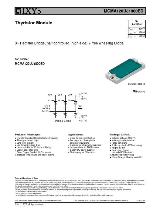
3~ Rectifier Bridge, half-controlled (high-side) + free wheeling DiodeThyristor ModulePart numberMCMA120UJ1800EDBackside: isolatedFeatures / Advantages:Applications:Package:● Thyristor/Standard Rectifier for line frequency ● Planar passivated chips ● Long-term stability● Low forward voltage drop● Leads suitable for PC board soldering ● Copper base plate withDirect Copper Bonded Al2O3-ceramic ● Improved temperature and power cycling● Diode for main rectification ● For single and three phase bridge configurations● Supplies for DC power equipment ● Input rectifiers for PWM inverter ● Battery DC power supplies ● Field supply for DC motorsE2-Pack● Industry standard outline ● RoHS compliant● Soldering pins for PCB mounting ● Height: 17 mm● Base plate: Copper internally DCB isolated ● Advanced power cycling● Phase Change Material available● Isolation Voltage: V~3600The data contained in this product data sheet is exclusively intended for technically trained staff. The user will have to evaluate the suitability of the product for the intended application and the completeness of the product data with respect to his application. The specifications of our components may not be considered as an assurance of component characteristics. Theinformation in the valid application- and assembly notes must be considered. Should you require product information in excess of the data given in this product data sheet or which concerns the specific application of your product, please contact your local sales office.Due to technical requirements our product may contain dangerous substances. For information on the types in question please contact your local sales office.Should you intend to use the product in aviation, in health or life endangering or life support applications, please notify. For any such application we urgently recommend - to perform joint risk and quality assessments;- the conclusion of quality agreements;- to establish joint measures of an ongoing product survey, and that we may make delivery dependent on the realization of any such measures.Terms and Conditions of UsageRRM 1800I 120FSM 500DAV V =V A A==I 3~RectifierRatingsDate Code LocationC M M A 120UJ 1800EDPart descriptionThyristor (SCR)Thyristor(up to 1800V)3~ Rectifier Bridge, half-controlled (high-side) + free wheeling Diode E 2-Pack Module====Current Rating [A]Reverse Voltage [V]==== PackageT op °C M D Nm 6mounting torque3T VJ °C 150virtual junction temperature -40Weight g 176Symbol Definitiontyp.max.min.Conditionsoperation temperature Unit V V t = 1 second Vt = 1 minuteisolation voltagemm mm 6.012.0d Spp/App creepage distance on surface | striking distance through air d Spb/Apb terminal to backsideI RMS RMS current100A per terminal125-40terminal to terminal E2-PackDelivery ModeQuantityCode No.Ordering Number Marking on Product Ordering 50/60 Hz, RMS; I ≤ 1 mAISOL MCMA120UJ1800ED 510125Box 6MCMA120UJ1800ED Standard 3600ISOLT stg °C 125storage temperature-403000m Ω0 max R 0 maxslope resistance *10.5Outlines E2-PackThyristor。
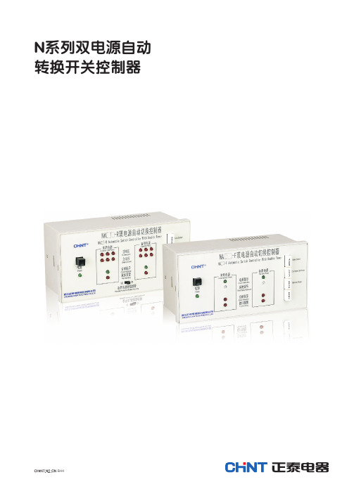
正泰NA1双电源说明书
方框1
42 11
1
3
熔断器
Un Ua Ub Uc
XT 2
4
12 14
30 32
34 38 40 19
23 21 25
智能控制器
F DT SA
DF1
DF2
DF3
DF4
M
XT 1 3 5
13 15
29 31 33 35 39
18 20 22
24 26
F1 公共端 F2 发电机停止信号 F4 发电机启动信号
1.3 正常工作条件和安装条件 1.3.1 周围空气温度:上限值不超过+40℃;下限值不低于-5℃;24h内的平均值不超过+35°。 环境温度低于-5℃时,订货时需要特殊注明。 环境温度超过+40℃时,需按照万能式断路器使用说明书相关的条款要求进行降容使用。 1.3.2 极限大气条件按照N万能式断路器使用说明书相关条款的要求。 1.3.3 安装地点:安装地点的海拔高度不超过2000m。 安装地点海拔高度超过2000m时,需按照N系列万能式断路器使用说明书中相关条款要求进行降容使用。 1.3.4 污染等级为3级。 1.3.5 安装类别为IV类。 1.3.6 安装条件:双电源系统的两台N系列万能式断路器在相邻的两个配电柜中进行水平安装,两台断路 器左侧板之间的最大距离不超过1.5m,两台断路器之间安装钢缆联锁进行联锁。双电源系统的两台N系 列万能式断路器在1个配电柜中进行上下安装,两台断路器底板之间的最大距离不超过0.9m,两台断路 器之间安装钢缆联锁或杠杆联锁。
4.2 NA1-2000~6300产品配双电源自动转换开关电器控制接线图
N系列双电源自动转换开关电器控制器
Modicon ABLM1A24012电源供应设备说明书
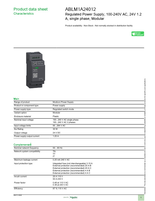
Product data sheetCharacteristicsABLM1A24012Regulated Power Supply, 100-240V AC, 24V 1.2A, single phase, ModularProduct availability : Non-Stock - Not normally stocked in distribution facilityMainRange of productModicon Power Supply Product or component type Power supplyPower supply type Regulated switch mode Variant option Modular Enclosure material PlasticNominal input voltage 100...240 V AC single phase 100...240 V AC 2 phases Input voltage limits 90...264 V AC Kw Rating 30 W Output voltage24 V DC Power supply output current1.25 AComplementaryNominal network frequency 50…60 Hz Network system compatibilityTN TT ITMaximum leakage current 0.25 mA 240 V ACInput protection typeIntegrated fuse (not interchangeable) 3.15 A External protection (recommended) 20 A B External protection (recommended) 20 A C External protection (recommended) 4 A B External protection (recommended) 4 A C Inrush current 25 A 115 V 50 A 230 V Power factor 0.48 at 115 V AC 0.38 at 230 V AC Efficiency87 % 115 V ACi s c l a i m e r : T h i s d o c u m e n t a t i o n i s n o t i n t e n d e d a s a s u b s t i t u t e f o r a n d i s n o t t o b e u s e d f o r d e t e r m i n i n g s u i t a b i l i t y o r r e l i a b i l i t y o f t h e s e p r o d u c t s f o r s p e c i f i c u s e r a p p l i c a t i o n s87 % 230 V ACOutput voltage adjustment24...28 VPower dissipation in W5 WCurrent consumption< 0.8 A 115 V AC< 0.6 A 230 V ACTurn-on time< 2 sHolding time> 20 ms 115 V AC> 60 ms 230 V ACStartup with capacitive loads3000 µFResidual ripple< 100 mVExpected capacitor life time10 year(s)Meantime between failure [MTBF]2500000 h at 77 °F (25 °C), full load1000000 h at 131 °F (55 °C), 80 % loadOutput protection type Against overload and short-circuits automatic resetAgainst over temperature manual resetAgainst overvoltage manual resetConnections - terminals Screw connection 0.5...1.5 mm², AWG 20...AWG 16) without wire end ferrule input/outputScrew connection 0.5...1 mm², AWG 20...AWG 18) with wire end ferrule input/output Line and load regulation< 0.5 %line< 1 %loadStatus LED Output voltage 1 LED Green)Maximum Depth 2.19 in (55.6 mm)Maximum Height 3.58 in (91 mm)Maximum Width 1.42 in (36 mm)Net Weight0.37 lb(US) (0.170 kg)Output coupling SerialParallelMounting support Top hat type TH35-15 rail IEC 60715Top hat type TH35-7.5 rail IEC 60715Double-profile DIN railpanel mountingEnvironmentStandards EN 62368-1EN/IEC 61010-1EN 61010-2-201EN/IEC 61204-3EN 61000-6-1EN 61000-6-2EN 61000-6-3EN 61000-6-4EN 61000-3-2EN 61000-3-3UL 62368-1UL 61010-1UL 61010-2-201CSA C22.2 No 62368-1CSA C22.2 No 61010-1CSA C22.2 No 61010-2-201Product certifications CECUL ListedCUL RecognizedRCMCB SchemeEACKCNEC class 2Operating altitude< 6561.68 ft (2000 m) overvoltage category III2000 m...5000 m overvoltage category IIShock resistance100 m/s² 11 msIP degree of protection IP20Ambient air temperature for operation-13…131 °F (-25…55 °C) without current derating)131…158 °F (55…70 °C) with current derating of 2.67 % per °C)Ambient air temperature for storage-40…185 °F (-40…85 °C)Relative humidity0…95 % without condensationOvervoltage category IIElectrical shock protection class Class II without PE connectionPollution degree2Vibration resistance 3 mm 2…9 Hz)IEC 60721-3-310 m/s² 9…200 Hz)IEC 60721-3-3Electromagnetic immunity Immunity to electrostatic discharge 6 kV contact discharge) EN/IEC 61000-4-2Immunity to electrostatic discharge 9 kV air discharge) EN/IEC 61000-4-2Electromagnetic field immunity test 10 V/m 80 MHz...2 GHz) EN/IEC 61000-4-3Electromagnetic field immunity test 5 V/m 2...2.7 GHz) EN/IEC 61000-4-3Electromagnetic field immunity test 3 V/m 2.7...6 GHz) EN/IEC 61000-4-3Immunity to fast transients 4 kV on input-output) EN/IEC 61000-4-4Surge immunity test 3 kV between power supply and earth) EN/IEC 61000-4-5Surge immunity test 1.5 kV between phases) EN/IEC 61000-4-5Immunity to conducted disturbances 10 Vrms 0.15...80 MHz) EN/IEC 61000-4-6Immunity to magnetic fields 30 A/m 50...60 Hz) EN/IEC 61000-4-8Immunity to voltage dips 100 % 1 cycle) EN/IEC 61000-4-11Immunity to voltage dips 60 % 10 cycles) EN/IEC 61000-4-11Immunity to voltage dips 30 % 25 cycles) EN/IEC 61000-4-11Disturbing field emission EN 55016-2-3Limits for harmonic current emissions EN 61000-3-2Conducted disturbance emission EN 55016-1-2Conducted disturbance emission EN 55016-2-1Electromagnetic emission Conducted emissions EN 61000-6-3Radiated emissions EN 61000-6-4Dielectric strength3000 V AC input/outputOrdering and shipping detailsCategory22525 - ABL8 AND ABL7 POWER SUPPLIEDiscount Schedule CP12GTIN00785901704706Package weight(Lbs)1 lb(US) (0.45 kg)Returnability YesCountry of origin CNOffer SustainabilitySustainable offer status Green Premium productREACh Regulation REACh DeclarationEU RoHS Directive Pro-active compliance (Product out of EU RoHS legal scope)EU RoHS DeclarationMercury free YesRoHS exemption information YesChina RoHS Regulation China RoHS declarationEnvironmental Disclosure Product Environmental ProfileCircularity Profile End of Life InformationWEEE The product must be disposed on European Union markets following specific waste collection andnever end up in rubbish bins.Electrical Safety●If the unit is use in a manner not specified by the manufacturer, the protection provided by the equipment may be impaired.●For means of disconnection a switch or circuit breaker, located near the product, must be included in the installation. A marking as disconnecting device for th ●The device has an internal fuse. The unit is tested and approved with branch circuit protective device up to 20A. This circuit breaker can be used as disconne ●The power supply is only suitable for audio, video, information, communication, industrial and control equipment.DimensionsSide and Rear ViewConnections and SchemaConnections and Schema Correct Parallel Connection(1) :LoadIncorrect Parallel Connection(1) :LoadABLx1Axxxxx-1 = ABLx1Axxxxx-2 max 2 x ABLx1AxxxxxL1 = L2∆V max 25 mVL Load < 90% 2 x L nomOutput Voltage Balancing(1) :R Load1(2) :R Load2R Load1= R Load2I1= I 2= ~ I nomSeries Connection(1) :V out1(2) :V out2(3) : 2 x Diode, V RRM> 2 x V out1/2, I F > 2 x I nom1/2(4) :V Load = 2 x V out(5) :LoadConnections and Schema Connections and Schema(1) :AmbientPerformance Curves Performance CurveX :Ambient Temperature (ºC)Y :Percentage of Max Load (%)1 :Mounting A & B, altitude 2000M2 :Mounting A & B, altitude 5000MMounting and ClearanceMountingMounting Position AMounting Position BIncorrect Mounting。
dr12024开关电源说明书
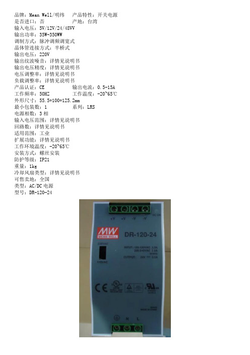
品牌:Mean Well/明纬产品特性:开关电源是否进口:否产地:台湾
输入电压:5V/12V/24/48VV
输出功率:35W-350WW
调制方式:脉冲调频调宽式
晶体管连接方式:半桥式
输出电压:220V
输出纹波噪音:详情见说明书
输出电压精度:详情见说明书
电压调整率:详情见说明书
负载调整率:详情见说明书
产品认证:CE 输出电流:0.5-15A 工作频率:50HZ 工作温度:-20~65℃外形尺寸:55.5*100*125.2mm
最小包装数:1 系列:LRS
电源相数:3相
输入电压范围:详情见说明书
回路数:详情见说明书
适用范围:工业
扩展功能:详情见说明书
工作环境温度:-20~65℃
安装方式:螺丝安装
防护等级:IP21
重量:1kg
冷却风扇类型:详情见说明书
可售卖地:全国
类型:AC/DC电源
型号:DR-120-24。
IAI电缸
0.5 400 500
37.4
ə3 ི Ma உડ ܿনᎳၤȃ!
Ma உડ! ؚ٤নᎳၤə3
49.1 2.3
M.E.
ᄵ!ڋ S.E.
2-φ5H7 ਭ૾ແ 10
60
ኊ!ݞ
50.9 13.5
2.5 M.E.ə2
118.5
80.6 59 50 48.5 32 36
A ؠၤ!
55
58
φ8
4.5
4.5
9
宽 58mm ERC2-RGS6C
11
臂平 杆台
宽 68mm ERC2-RGS7C
13
扁 平
宽 58mm ERC2-RGD6C
15
旋夹
转爪
宽 68mm ERC2-RGD7C
17
型
专无 用尘 型室
防 滴 型
控 制 器
联
C轴 器
直
D接
折
R返
2 控制器内置型
脉冲马达
20P
脉冲马达
28P
脉冲马达
35P
负载伸出长度
3 ERC2-SA6C
Ma
Mb
L
Mc
Ma
Mc
L
尺寸图 CAD 图纸可从主页下载。 www.iai-robot.co.jp
2维 CAD
※ 对于反原点规格,马达侧的尺寸(从 ME 到原点的距离) 与反马达侧的尺寸相反。
60
5
50
5
9 32±0.02 9 4-M5 ແ 10
22 ˄ਭ૾ৱُ࢞_0.02˅! 31
600
(mm)
水平(kg) 垂直(kg)
(mm)
KYN28A-12正泰电气

注:1、电流互感器的短路容量应单独考虑; 2、ZN63A-12技术参数详见本公司相应样本。
P5.
中压开关设备类
5 结构形式
开关设备由柜体和中置可抽了部件 (即手车) 两大部分组成。柜体分四个单独的隔室,外壳防护等级 为IP4X,各小室外间和断路器室门打开时防护等级为IP2X。具有架空进出线、电缆进出线及其它功能方 案,经排列、组合后能成为各种方案形式的配电装置。本开关设备可以从正面进行安装调试和维护,因 此它可以背靠背组成双重排列和靠墙安装,提高了开关设备的安全性、灵活性,减少了占地面积。
钢铁冶金
上海宝钢集团 中国首钢集团 马鞍山钢铁集团 天津钢铁有限公司 江苏南京钢铁集团公司
配电系统
山西阳城电厂 西电东送贵州黔北电厂 西电东送云南滇东电厂 国电河北龙山发电厂
交通运输
首都国际机场 北京地铁 上海、天津铁路局 广州铁路集团公司 京沪、京九、兰新、郑徐、 浙赣铁路电气化工程
广电科研
国家广播电视总局 中央电视台 中央电视塔电力系统 新华社 钓鱼台国宾馆 中国原子能科学院
KYN28A-12(Z)系列
铠装移开式交流金属封闭开关设备
2011-037CN0809
一、质量保证
中压开关设备类
KYN28A-12(Z)系列铠装移开式交流金属封闭开关设备
KYN28A-12(Z)/T1250-31.5 产品认证证书
KYN28A(GZS1)-12(Z)/T3150-40 产品认证证书
1
3
1 2 3
7 产品安装、地基图
7.1 KYN28A-12(Z)(GZS1)开关设备
N
1 23
1 1 3
11 22
3
2
2 4
AC-DC小型隔离开关电源模块12W
■产品特性:●全球通用范围交流/直流输入●高效率、高功率密度●输出内置稳压滤波、低纹波零噪音●体积小:40*32*16mm●保护种类:过载保护/短路保护/过热保护●内置脉冲群衰减器●内置EMC电路符合EN55032Class B●ClassⅡ隔离级别(安规)●待机低功耗,绿色环保●无需外围电路设计、PCB焊接方式●塑料外壳,自然冷却■产品应用:●工业电气设备●机械设备●工业自动化设备●手持电子设备●无线网络●电信/数据通信●仪器仪表●智能化领域■产品描述:电源模块具有交直流两用宽电压输入,内置防雷防浪涌电路,内置脉冲群衰减器,内置差模、共模滤波,效率高达86%(全系列同步整流)和低于0.3W的超低空载功耗等优点。
电源采用真空灌封封装,具有防尘和防潮功能。
本系列电源符合EN55032Class B电磁兼容(EMC)特性和ClassⅡ隔离级别(安规),典型电路即可通过认证测试。
■产品型号说明:AP XX NXX Zero系列特征如:Zero零纹波噪音输出功率如:12-12W24-24W输出电压如:05-5V12-12V系列名如:AP系列内置EMC电路■输入电气规格:■输出电气规格:■纹波与噪音特性:■EMC特性:EMC特性测试项目测试标准传导骚扰(CE)EN55032:2015CLASSBEMI辐射骚扰(RE)EN55032:2015CLASSB电压波动和闪变EN61000-3-3:2013静电放电(ESD)EN61000-4-2:2009Contact±4KV Air±8KV辐射抗扰度EN61000-4-3:2006+A1:2008+A2:2010 EMS脉冲群抗扰度EN61000-4-4:2012浪涌抗扰度EN61000-4-5:2014传导骚扰抗扰度EN61000-4-6:2014电压暂降、跌落和短时中断抗扰度EN61000-4-11:2017■通用特性:项目工作条件@测试结论开关频率65KHz短路保护可长期短路,自恢复过载保护>Load150%,可恢复过热保护模块表面温度在80℃(±4℃),进入过热保护耐压测试Input-Output3000VAC/1min(耐压测试属于极限破坏实验,不可多次测试)工作温度-40~70℃(详细使用情况参考温度&降额曲线)模块重量39g(±2g)外壳尺寸40*3*16mm外壳材质耐高温塑料外壳冷却方式自然冷却安全等级CLASSⅡ备注如未特别说明,所有规格参数均在输入电压为220VAC,环境温度25℃下测试。
ZFZ-812使用说明书(c版) 分相:一套双跳 电压自动切换双位置
0XJ 463 224第 2 页共 33 页旧底图总号底图总号签字日期1概述1.1装置用途装置作为分相断路器操作的辅助控制回路,适用于220kV及以上具有双跳闸线圈的一台断路器控制操作之用。
1.2 装置综述装置共一层箱,包括十三个插件,均采用插件形式,保证了配置的灵活方便,各插件有三个电压切换插件及ZJ备用继电器回路插件,TXJ信号回路插件,HHJ、ZHJ、SHJ合闸继电器回路插件,TBJ防跳继电器回路插件,两个TJR、TJQ、STJ三跳继电器回路插件,两个HWJ合位继电器回路插件,TWJ跳位继电器回路插件, YJJ压力监视回路插件。
装置除能正确反映跳、合情况还设有防止跳跃的防跳闭锁继电器TBJ,利用其本身特点和触点不同的回路连接,能防止断路器多次“跳—合”现象。
同时,可实现电压的自动切换,保证双母线(带旁路)接线系统上所连接的电气元件在运行时,其一次系统和二次系统相对应,以免保护及自动装置发生误动或拒动。
为了防止在运行中由于控制跳闸的气(液)压触点接触不良造成气(液)压闭锁环节失灵,压力监视继电器1YJJ、2YJJ 、3YJJ、4YJJ还设有预告信号。
2 技术参数2.1 基本数据2.1.1 额定数据a.直流电压:220V或110V;b.跳闸保持电流:0.25A~4A;c.合闸保持电流:0.25A~4A。
2.1.2 装置功率消耗在额定直流电压下,直流电压回路功率消耗正常情况下不大于60W。
2.1.3触点性能装置的出口触点,在电压不大于250V,电流不大于0.5A,时间常数为5ms±0.75ms的直流有感负荷电路中,断开容量为50W,长期允许通过电流为5A。
装置的信号触点,在电压不大于250V,电流不大于0.5A,时间常数为5ms±0.75ms的直流有感负荷电路中,断开容量为30W,长期允许通过电流为3A。
2.1.4装置约重20kg。
2.2 绝缘性能装置所有电路对外壳及电气上无联系的各电路之间的绝缘电阻在正常校验的标准大气条件下,不小于100MΩ。
ArmorBlock 2-Port EtherNet IP 16-点数字模块参考手册
Wiring DiagramsArmorBlock 2-Port EtherNet/IP 16-point Digital Module Catalog Number: 1732E-8X8M12DRParts ListYour package contains one 1 732E ArmorBlock® module and these pinout guide wiring instructions.For complete installation instructions, see module publication number table and visit rok.auto/literature. Module Publication NumberModule Publication Number ArmorBlock 2-Port EtherNet/IP™ Module1732E-IN004ATTENTION: Two sets of mounting holes are used to mount the module directly to a panel ormachine. Mounting holes accommodate #8 (M4) pan head screws. The torque specification is1.13 N•m (10 in•lb).ATTENTION: This equipment is considered Group 1, Class A industrial equipment according toIEC/CISPR 11. Without appropriate precautions, there may be difficulties with electromagneticcompatibility in residential and other environments due to conducted and radiateddisturbance.ATTENTION: To comply with UL restrictions, this equipment must be powered from a sourcecompliant with the following: Limited Voltage/Current.2Rockwell Automation Publication 1732E-WD001G-EN-P - April 2020ArmorBlock 2-Port EtherNet/IP 16-point Digital Module Wiring DiagramsI/O Connectors Micro-style 5-Pin Input Female Connector Micro-style 5-Pin Output Female ConnectorEtherNet/IP ConnectorD-Code M12 Network Female ConnectorAuxiliary Power ConnectorMini-style 4-Pin Input Male Receptacle12453(View into connector)Pin 1Sensor source voltagePin 2 Input BPin 3 ReturnPin 4 Input APin 5 PE4480712453(View into connector)Pin 1Not used Pin 2 Output B Pin 3 Return Pin 4 Output A Pin 5 PE44807(View into connector)Pin 1M12_Tx+Pin 2 M12_Rx+Pin 3 M12_Tx-Pin 4 M12_Rx-Pin 5 Connector shell shield FE 4231544808423144809(View into receptacle)Pin 1Output power+Pin 2Sensor/MDL power+Pin 3Sensor/MDL power-Pin 4Output power-ArmorBlock 2-Port EtherNet/IP 16-point Digital Module Wiring DiagramsRockwell Automation Publication 1732E-WD001G-EN-P - April 20203SpecificationsEnvironmental Specifications AttributeValue Temperature, operatingIEC60068-2-1 (Test Ad, Operating Cold),IEC60068-2-2 (Test Bd, Operating Dry Heat),IEC 60068-2-14 (Test Nb, Operating Thermal Shock):-20...+60 °C (-4…+140 °F)Temperature, ambient, max 60 °C (140 °F)Operating voltage 12…30V DC Output current per channel, max0.5 A Output current per module, max4.0 A Enclosure type ratingMeets IP65/66/67/69K (when marked), and Type 4X, 6P with receptacle dust caps or cable termination.CertificationsCertification (when product ismarked)(1)(1)See the Product Certification link at rok.auto/certifications for Declarations of Conformity, Certificates, and other certification details.Value c-UL-us UL Listed Industrial Control Equipment, certified for US and Canada. See UL File E322657.CE European Union 2014/30/EU EMC Directive, compliant with:EN 61326-1; Meas./Control/Lab., Industrial Requirements EN 61000-6-2; Industrial Immunity EN 61000-6-4; Industrial Emissions EN 61131-2; Programmable Controllers (Clause 8, Zone A & B)RCM Australian Radiocommunications Act, compliant with:EN 61000-6-4; Industrial EmissionsKC Korean Registration of Broadcasting and Communications Equipment, compliant with: Article 58-2 of Radio Waves Act, Clause 3EtherNet/IPODVA conformance tested to EtherNet/IP specifications.Publication 1732E-WD001G-EN-P - April 2020 | Supersedes Publication 1732E-WD001F-EN-P - April 2017Copyright © 2020 Rockwell Automation, Inc. All rights reserved. Printed in Singapore.Rockwell Otomasyon Ticaret A.Ş. Kar Plaza İş Merkezi E Blok Kat:6 34752, İçerenköy, İstanbul, Tel:+90(216)5698400 EEE Yönetmeliğine UygundurPN-562273 Allen-Bradley, ArmorBlock, expanding human possibility, FactoryTalk, Rockwell Automation and TechConnect are trademarks of Rockwell Automation,Inc.EtherNet/IP is a trademark of ODVA, Inc.Trademarks not belonging to Rockwell Automation are property of their respective companies.Waste Electrical and Electronic Equipment (WEEE)Rockwell Automation maintains current product environmental compliance information on its website at rok.auto/pec .At the end of life, this equipment should be collected separately from any unsorted municipal waste.Rockwell Automation SupportUse these resources to access support information.Documentation FeedbackYour comments help us serve your documentation needs better. If you have any suggestions on how to improve our content, complete the form at rok.auto/docfeedback .Technical Support CenterFind help with how-to videos, FAQs, chat, user forums, and product notification updates.rok.auto/support KnowledgebaseAccess Knowledgebase articles.rok.auto/knowledgebase Local Technical Support Phone NumbersLocate the telephone number for your country.rok.auto/phonesupport Literature LibraryFind installation instructions, manuals, brochures, and technical data publications.rok.auto/literature Product Compatibility and Download Center (PCDC)Download firmware, associated files (such as AOP, EDS, and DTM), and access product release notes.rok.auto/pcdc。
EPM12V2非隔离直流电源模块说明书
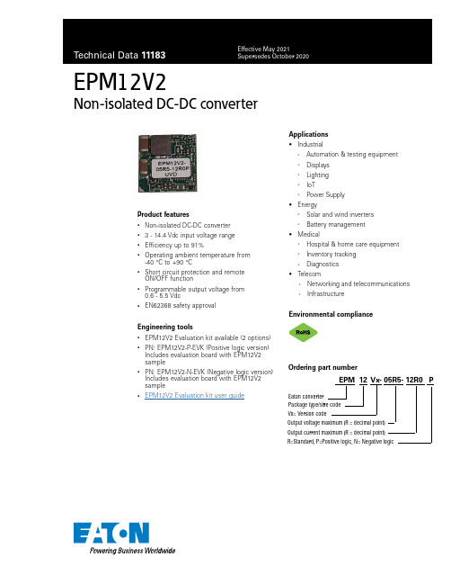
EPM12V2Non-isolated DC-DC converterProduct features• Non-isolated DC-DC converter • 3 - 14.4 Vdc input voltage range • Efficiency up to 91%•Operating ambient temperature from -40 °C to +90 °C•Short circuit protection and remote ON/OFF function•Programmable output voltage from 0.6 - 5.5 Vdc•EN62368 safety approvalEngineering tools• EPM12V2 Evaluation kit available (2 options)•PN: EPM12V2-P-EVK (Positive logic version)Includes evaluation board with EPM12V2 sample•PN: EPM12V2-N-EVK (Negative logic version)Includes evaluation board with EPM12V2 sample•EPM12V2 Evaluation kit user guideEPM 12 Vx- 05R5- 12R0 PEaton converter Package type/size codeVx= Version codeOrdering part numberR=Standard, P=Positive logic, N= Negative logicOutput voltage maximum (R = decimal point)Output current maximum (R = decimal point)Applications• Industrial• Automation & testing equipment • Displays • Lighting • IoT•Power Supply• Energy• Solar and wind inverters •Battery management• Medical• Hospital & home care equipment • Inventory tracking •Diagnostics• Telecom• Networking and telecommunications •InfrastructureEnvironmental compliance2Technical Data 11183Effective May 2021EPM12V2 Non-isolated DC-DC converter/electronicsSpecificationsParameterConditionsMinimumTypicalMaximumUnitInputInput voltage range 31214.4Vdc Start-up voltage0%~100% load3Vdc VULO2.6VRemote ON/OFFPositiveDC-DC ON DC-DC OFF Open or 1.6 V ≤ Von/off ≤ 5.5 V Short to Gnd or 0 V ≤ Von/off ≤ 0.6 V Negative DC-DC ON Short to Gnd or 0 V ≤ Von/off ≤ 0.6 VEMCESDEN61000-4-2Air ± 8 kV Contact ± 8 kV Criteria B Fast transient EN 61000-4-4, ±2 kV Criteria B SurgeEN 61000-4-5, ±2 kV Criteria A1. The output voltage range is limited by Vin. (Vout ≤ Vin – 2 Vdc)2. The ripple & noise are measured with 47 µF + 47 µF + 0.1 µF capacitor at 20 MHz BW.3. SYNC frequency must be greater than operating frequency, externally tie SYNC to GND if synchronization functionality not required.4. All specifications valid at nominal input voltage, full load and +25 ˚C after warm-up time unless otherwise stated.5. The product information and specifications are subject to change without prior notice.3Technical Data 11183Effective May 2021EPM12V2Non-isolated DC-DC converter /electronics Output voltage vs. input voltage16 14 12 10 8 6 42 014.43I n p u t v o l t a g e (V )Output voltage (V)Derating curvePart numberInput voltageOutput voltageOutput current @ full loadInput current @ no loadEfficiency 1 typicalCapacitive load 2maximum ON/OFF LogicEPM12V2-05R5-12R0P 3 - 14.4 Vdc 0.6 - 5.5 Vdc 12 A 30 mA 91%200 μF Positive EPM12V2-05R5-12R0N3 - 14.4 Vdc0.6 - 5.5 Vdc12 A30 mA91%200 μFNegative1. The no load input current is test by 0.6 V output.2. The efficiency is test by nominal input, 5 Vout and full load @ +25 °C.3. The capacitive load is test by minimum input and constant resistive load4. All specifications valid at 12 V input, full load and +25 °C after warm-up time unless otherwise stated.Selection guideMeasure methodDC/DC Converter-Vin-Vout47uF47uF 0.1uFThe derating curve was measured at 12 V input and 5 V output.* The derating curve is at 7 V input and 5 V outputL o a d (%)20 LFM (0.1 m/s)*100 LFM(0.5 m/s)300 LFM (1.5 m/s)500 LFM (2.5 m/s)Temperature (°C)4Technical Data 11183Effective May 2021EPM12V2 Non-isolated DC-DC converter/electronicsApplication informationLogic type active mode Positive LogicDC/DC ON : Q1 OFF DC/DC OFF : Q1 ON Negative Logic DC/DC ON : Q1 ONDC/DC OFF: Q1 OFFOutput voltage trimOutput voltage Calculated Rtrim (kΩ)5.0 V 2.7273.3 V 4.4442.5 V6.3161.8 V 101.5 V 13.31.2 V 200.6 V∞ (Open)Trim resistor equationRtrim (k Ω) = 12K Vo−0.6Power goodPower good monitor output. This open-drain output goes low during overcurrent, short-circuit, UVLO, overvoltage and undervoltage, overtemperature, or when the output is not regulated (such as a pre-bias output). An external pullup resistor to VDD or to an external rail is required. Included is a 20-μs deglitch filter. PGOOD pin can be connected through a pullup resistor suggested value 100 k Ω) to a source of 5 Vdc or lower.SynchronizationThe module switching frequency can be synchronized to a signal with an external frequency within a specified range. Synchronization can be done by using the external signal applied to the SYNC pin of the module, with the converter being synchronized by the rising edge of the external signal. The electrical specifications table specifies the requirements of the external SYNC signal. If the SYNC pin is not used, the module should free run at the default switching frequency. If synchronization is not being used, connect the SYNC pin toGND.Output voltage sequencingThe SEQ pin can be used when master-slave power-supply tracking is required.The voltage applied to the SEQ pin should be scaled down by the same ratio as used to scale the output voltage down to the reference voltage of the module. This is accomplished by an external resistive divider connected across the sequencing voltage before it is fed to the SEQ pin.The minimum recommended delay between the ON/OFF signal and the sequencing signal is 10 ms to ensure that the module output is ramped up according to the sequencing signal. This ensures that the module soft-start routine is completed before the sequencing signal is allowed to ramp up.When an analog voltage is applied to the SEQ pin, theoutput voltage tracks this voltage until the output reaches the set-point voltage. The final value of the SEQ voltage must be set higher than the set-point voltage of the module. The output voltage follows the voltage on the SEQ pin on a one-to-one basis. By connecting multiple modules together, multiple modules can track their output voltages to the volt-age applied on the SEQ pin.To initiate simultaneous shutdown of the modules, the SEQ pin voltage is lowered in a controlled manner. The output voltage of the modules tracks the voltages below theirsetpoint voltages on a one-to-one basis. A valid input voltage must be maintained until the tracking and output voltagesreach ground potential.The SEQ pin can be used when master-slave power-supply tracking is requiredRemote ON/OFF5Technical Data 11183Effective May 2021EPM12V2Non-isolated DC-DC converter /electronics Mechanical dimension and pinning - inchesProjection: Third angle projection Tolerance: ± 0.01Pad 1&5~12 = 0.04 x 0.04Pad 2~4 = 0.07 x 0.157NC = no connectionPad 1 & 5~17 = 0.041” x 0.041” Pad 2&4 = 0.165” x 0.074”Markingxxx= lot codeEMC filtering circuitDC/DC ConverterLoadVinC1L1+VinGNDC2L2C3GVoGL3ClassC1L1C2L2 C3L3Class A 100 µF/ 25 V 8 mH 100 µF/ 25 V 12 mH 470 µF/ 25 V 35 µH ETF and surge circuitDC/DC ConverterLoadTVS C1TVS C1Eaton P4SMA13CA 10000 µF 25 VRecommended pad layoutPinFunctionPinFunction1On/Off 10PGOOD 2Vin 11SYNC 3GND 12VS-4Vout 13SIG_GND 5VS+ (Sense)14NC 6TRIM 15NC 7GND 16NC 8NC 17NC9SEQ6Technical Data 11183Effective May 2021EPM12V2 Non-isolated DC-DC converter/electronicsPackaging- InchesEatonElectronics Division 1000 Eaton Boulevard Cleveland, OH 44122 United States /electronics© 2021 EatonAll Rights Reserved Printed in USA Publication No. 11183 May 2021Technical Data11183Effective May 2021EPM12V2Non-isolated DC-DC converterLife Support Policy: Eaton does not authorize the use of any of its products for use in life support devices or systems without the express writtenapproval of an officer of the Company. Life support systems are devices which support or sustain life, and whose failure to perform, when properly usedin accordance with instructions for use provided in the labeling, can be reasonably expected to result in significant injury to the user.Eaton reserves the right, without notice, to change design or construction of any products and to discontinue or limit distribution of any products. Eaton alsoreserves the right to change or update, without notice, any technical information contained in this bulletin.Eaton is a registered trademark. All other trademarks are property of their respective owners.Follow us on social media to get thelatest product and support information.General informationPick and placeThe 12 A open frame modules use an open frame construction and are designed for a fully automated pick and place assembly process.MSL ratingThe 12 A Open frame modules have a MSL rating of 3.Storage and handlingThe recommended storage environment and handling procedures for moisture-sensitive surface mount packages is detailed in J-STD-033 (Handling, packing, shipping and use of moisture/reflow sensitive surface mount devices). Moisture barrier bags (MBB) with desiccant are required for MSL ratings of 3 or greater. These sealed packages should not be broken until time of use. Once the original packageis broken, the floor life of the product at conditions of 30°C and 60% relative humidity 168 hours varies according to the MSL rating (see J-STD-033). The shelf life for dry packed SMT packages will be a maximum of 12 months from the bag seal date, when stored at the following conditions: < 40 °C, < 90% relative humidity.Post solder cleaning and drying considerationsTo avoid contamination on the soldering pads extra care has to be taken when handling the boards. Clean soldering surfaces do not generate as many gases when the flux reduce the metal oxides or react with contaminants during the soldering process.NozzleThe module weight has been kept to a minimum by using open frame construction. Variables such as nozzle size, tip style, vacuum pressure and placement speed should be considered to optimize this process. Lead-free reflow profilePower systems will comply with J-STD-020 (Moisture/reflow sensitivity classification for nonhermetic solid state surface mount devices) for both Pb-free solder profiles and MSL classification procedures. This standard provides a recommended forced-air-convection reflow profile based on the volume and thickness of the package. The suggested Pb-free solder paste is Sn/Ag/Cu (SAC). The recommended linear reflow profile using Sn/Ag/Cu solder is shown. Soldering outside of the recommended profile requirestesting to verify results and performance.Profile Pb-free assemblyAverage ramp-up rate(Tsmaxto Tp) 3 °C/s max.PreheatTemperature Min. (Tsmin)Temperature Max. (Tsmax)Ts(Tsminto Tsmax)150 °C200 °C60-120 sTemperature (TP)245°CTime maintained aboveTemperature (TL)Time (tI)217°C60-150 sTime within 5°C of the specifiedPeak temperature (TP)20-40 sRamp down rate (TPto TL) 6 °C/s maxTime 25 °C to peak temperature8 minutes max.。
二分之一砖电源模块规格书Z28H24M600NNB

Z28H24M600NNB DC-DC电源模块【产品描述】1. 产品概述Z28H24M600NNB是标准1/2砖单路隔离稳压输出模块,额定输出电压24V,输出电流25A。
峰值效率可达95%,工作温度范围是:-55℃~ +100℃(壳温)。
采用领先预偏值启动同步整流技术提高了电源效率和同步整流的可靠性;采用有源钳位吸收技术降低了功率MOS管的电压应力,提高功率MOS管的可靠性;采用无光耦的电压反馈环提高了环路的响应速度与稳定性;采用主从模块民主均流法,使能模块能共享电流信号完成自动均流并联应用,可应用于高可靠性的冗余备份系统。
采用多层厚铜PCB与平面变压器工艺提高了电源的功率密度;采用铝外壳灌封工艺提高了电源的抗振动冲击,耐盐雾,耐高温能力。
2. 电气特性●工作电压范围: 16V ~ 40V (瞬态工作电压50V/1S)●额定输出功率600W●工作温度范围是:-55℃~ +100℃(壳温)●输入输出之间基本绝缘1500Vdc●模块可并联均流●固定开关频率PWM控制●无最小负载限制3. 控制特性●控制端子特性(负逻辑)●输出电压补偿●输出电压调节范围:50% ~ 110% Vo(Vo为额定输出电压24V)4. 保护功能●输入欠压锁死●输出过流保护●输出短路保护●输出过压保护●过温保护5. 命名规则6. 结构尺寸机械尺寸图单位mm 7. 引脚定义B +SHARE 并联均流正端(B型功能)3 -SHARE 并联均流负端(B型功能)4 -VIN 输入电压负端5 -VOUT 输出电压负端6 -SNS 远端采样负端7 TRIM 输出电压调整端8 +SNS 远端采样正端9 +VOUT 输出电压正端8. 电气特性输入电容Cin=220uF,输入电压28V,输出电容Cout=220uF,输出24V/600W,环境温度25℃(除非特别提及)。
压输入电压保护点14.4 14.7 15.0 V回差 1.0 V输入电容220 470 uF最大输入电流39 44 A 输入16V输入纹波电流168 240 mA 纹波电流峰峰值,如图9 空载输入电流230 300 mA 输入电压28V 禁止输入电流12 20 mA 输入电压28V,使能关机恢复时间200 us输出电压调节范围-50 +10 %输出过压保护28 29.8 31.8 V上升时间28 ms如图5,图7 开机瞬态启动延时时间35 ms输出过冲0 5 %V o9. 典型曲线图图1:效率与输出负载电流曲线图,外壳温度25℃图2:损耗功率与输出负载电流曲线图,外壳温度25℃图3:输出电流与铝基板温度降额曲线图图4:输出电压与输出电流曲线图10. 典型波形测试条件:输入电容Cin=220uF,输入电压28V,输出电容Cout=220uF,输出24V/600W,环境温度25℃图5:使能开机波形(负逻辑),1通道为使能控制电平,2通道为输出电压上升波形图6:使能关机波形(负逻辑),1通道为使能控制电平,2通道为输出电压下降波形图7:输入电压开机波形,1通道输入电压波形,2通道为输出电压上升波形图8:输入电压关机波形,1通道输入电压波形,2通道为输出电压下降波形图9:输入电流纹波,输入28V,输入端电容Cin=220uF,输出24V/600W图10:输出电压纹波,输入28V,输出24V/600W,输出电容Cout=220uF。
ZB1ZB2电器明细表
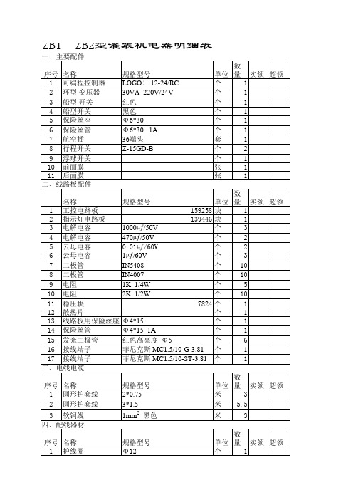
规格型号
单位 数量 实领 超领 159258 块 1 139446 块 1 1000µƒ/50V 个 3 470µƒ/50V 个 2 0.01µƒ/60V 个 2 1µƒ/60V 个 3 IN5408 个 10 IN4007 个 10 1K 1/4W 个 5 2K 1/2W 个 10 7824 个 1 个 1 Φ4*15 个 1 Φ4*15 1A 个 1 红色高亮度 Φ5 个 6 菲尼克斯 MC1.5/10-G-3.81 个 1 菲尼克斯 MC1.5/10-ST-3.81 个 1 规格型号 2*0.75 3*1.5 1mm2 黑色 规格型号 Φ12 Φ4 Φ2.5 Φ2.5 单位 数量 实领 超领 米 3 米 5.5 米 3
DHC3J-6L
个 个
1 1Leabharlann ZB1ZB2型灌装机电器明细表
规格型号 LOGO! 12-24/RC 30VA 220V/24V 红色 黑色 Φ6*30 Φ6*30 1A 36端头 Z-15GD-B 单位 数量 实领 超领 个 1 个 1 个 1 个 1 个 1 个 1 套 1 个 2 个 1 张 1 张 1
一、主要配件 序号 名称 1 可编程控制器 2 环型 变压器 3 船型 开关 4 船型开关 5 保险丝座 6 保险丝管 7 航空插 8 行程开关 9 浮球开关 10 前面膜 11 后面膜 二、线路板配件 名称 1 工控电路板 2 指示灯电路板 3 电解电容 4 电解电容 5 云母电容 6 云母电容 7 二极管 8 二极管 9 电阻 10 电阻 11 稳压块 12 散热片 13 线路板用保险丝座 14 保险丝管 15 发光二极管 16 接线端子 17 接线端子 三、电线电缆 序号 名称 1 圆形护套线 2 圆形护套线 3 软铜线 四、配线器材 序号 名称 1 护线圈 2 热缩管 3 接线管 4 环形线鼻
MCC半导体电源模块说明书
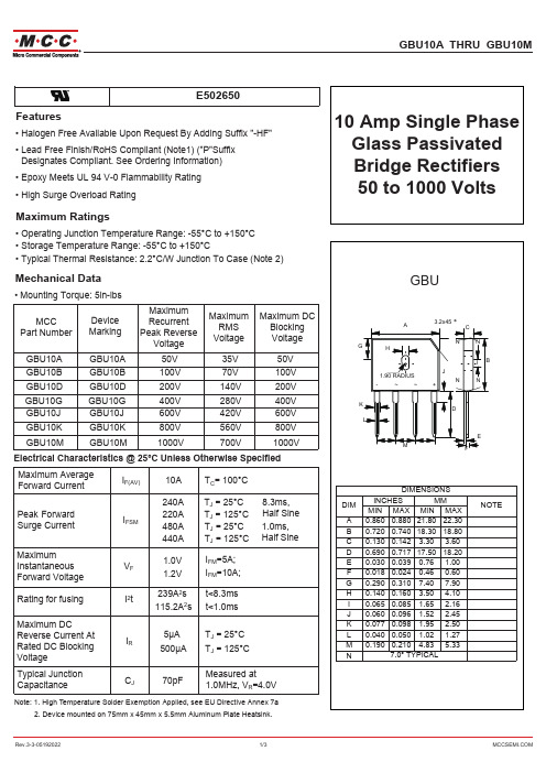
Rev.3-3-05192022
3/3
*%8$ THRU *%80
(
Features
• +DORJHQ)UHH$YDLODEOH8SRQ5HTXHVW%\$GGLQJ6XIIL[+) • Lead Free Finish/Ro+6 Compliant (Note1) ("P"Suffix
'esignatesCompliant. See 2rdering ,nformation) • (SR[\0HHWV8/9)ODPPDELOLW\5DWLQJ • +LJK6XUJH2YHUORDG5DWLQJ
280
240
200
160
120
80
40 8.3 ms Single Half Sine-Wave
0
1
10
100
Number of Cycles at 60 Hz
Fig. 4 - Typical Reverse Leakage Characteristics
10
1
TJ=100°C
0.1
0.01 20
TJ=25°C
A 0.860 0.880 21.80 22.30
B 0.720 0.740 18.30 18.80
C 0.130 0.142 3.30 3.60
D 0.690 0.717 17.50 18.20
E 0.030 0.039 0.76 1.00
F 0.018 0.024 0.46 0.60
G 0.290 0.310 7.40 7.90
GBU10A
GBU10A
50V
35V
50V
GBU10B
二分之一砖国产电源模块规格书Z28H12M600NNB
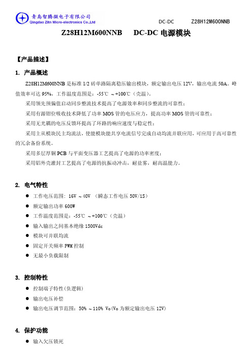
Z28H12M600NNB DC-DC电源模块【产品描述】1. 产品概述Z28H12M600NNB是标准1/2砖单路隔离稳压输出模块,额定输出电压12V,输出电流50A。
峰值效率可达95%,工作温度范围是:-55℃~ +100℃(壳温)。
采用领先预偏值启动同步整流技术提高了电源效率和同步整流的可靠性;采用有源钳位吸收技术降低了功率MOS管的电压应力,提高功率MOS管的可靠性;采用无光耦的电压反馈环提高了环路的响应速度与稳定性;采用主从模块民主均流法,使能模块能共享电流信号完成自动均流并联应用,可应用于高可靠性的冗余备份系统。
采用多层厚铜PCB与平面变压器工艺提高了电源的功率密度;采用铝外壳灌封工艺提高了电源的抗振动冲击,耐盐雾,耐高温能力。
2. 电气特性●工作电压范围: 16V ~ 40V (瞬态工作电压50V/1S)●额定输出功率600W●工作温度范围是:-55℃~ +100℃(壳温)●输入输出之间基本绝缘1500Vdc●模块可并联均流●固定开关频率PWM控制●无最小负载限制3. 控制特性●控制端子特性(负逻辑)●输出电压补偿●输出电压调节范围:50% ~ 110% Vo(Vo为额定输出电压12V)4. 保护功能●输入欠压锁死●输出过流保护●输出短路保护●输出过压保护●过温保护5. 命名规则6. 结构尺寸机械尺寸图单位mm 7. 引脚定义B +SHARE 并联均流正端(B型功能)3 -SHARE 并联均流负端(B型功能)4 -VIN 输入电压负端5 -VOUT 输出电压负端6 -SNS 远端采样负端7 TRIM 输出电压调整端8 +SNS 远端采样正端9 +VOUT 输出电压正端8. 电气特性输入电容Cin=220uF,输入电压28V,输出电容Cout=220uF,输出12V/600W,环境温度25℃(除非特别提及)。
压输入电压保护点14.4 14.7 15.0 V回差 1.0 V输入电容220 470 uF最大输入电流41 45 A 输入16V输入纹波电流200 400 mA 纹波电流峰峰值,如图9 空载输入电流250 330 mA 输入电压28V 禁止输入电流12 20 mA 输入电压28V,使能关机恢复时间200 us输出电压调节范围-50 +10 %输出过压保护14 14.5 16 V上升时间22 ms如图5,图7 开机瞬态启动延时时间28 ms输出过冲0 5 %V o9. 典型曲线图图1:效率与输出负载电流曲线图,外壳温度25℃图2:损耗功率与输出负载电流曲线图,外壳温度25℃图3:输出电流与铝基板温度降额曲线图图4:输出电压与输出电流曲线图10. 典型波形测试条件:输入电容Cin=220uF,输入电压28V,输出电容Cout=220uF,输出12V/600W,环境温度25℃图5:使能开机波形(负逻辑),3通道为使能控制电平,2通道为输出电压上升波形图6:使能关机波形(负逻辑),3通道为使能控制电平,2通道为输出电压下降波形图7:输入电压开机波形,3通道输入电压波形,2通道为输出电压上升波形图8:输入电压关机波形,3通道输入电压波形,2通道为输出电压下降波形图9:输入电流纹波,输入28V,输入端电容Cin=220uF,输出12V/600W图10:输出电压纹波,输入28V,输出12V/600W,输出电容Cout=220uF。
GE双电源ZTG

页码 控制电源 (CPS) .....................................................................21
原理图、标准&延时 ......................................................22 故障排除与诊断 .....................................................................23 维护与试验 ............................................................................. 24
检查与清洁处理 ............................................................ 24 服务................................................................................ 24 试验................................................................................ 24 更换部件 ................................................................................. 25 标准转换 .........................................................................25
GE Zenith Controls
ZTS/ZTSD 系列转换开关 40-4000 A
军用DCDC电源模块
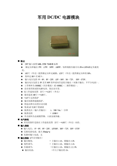
军用DC/DC电源模块■ 特点★ 28V输入按照MIL-STD-704D/E标准★额定功率输出5W,15W,30W,100W。
每种规格负载可从0%~150%额定负载变化。
★ 105℃(外壳)提供额定功率无减额;125℃(外壳)提供额定功率的50%。
★效率达80﹪至92﹪。
★输入电压包括4V~9V,9V~25V,18V~36V,36~72V, 80V~375V。
★输出电压包括2.5V直至90V的单或双任意组合输出(双独立输出,不平分电流)。
★工作频率为300KHZ(同步整流)或400KHZ(二极管整流)。
★没有使用钽或铝电解电容,保证高可靠。
★宽工作温度范围 -55℃∽+125℃(外壳)★储存温度-60℃∽+150℃。
★+137℃过热保护★输出短路和超载保护。
★软起动和自动重启动功能★集成LC电磁干扰滤波★隔离电压(输入至输出)- 1,500 Vdc/一分钟★隔离电阻 - 100MΩ★外壳材料为金属镀黑铜,六面金属屏蔽。
■ 电气特性★ 所有的指针是指在工作温度范围 -55℃~+105℃(外壳)内的。
■ 输入指标★ 输入电压:4V~9V,9V~25V,18V36V,36V~72V,80V~375V★ 反射纹波电流:最大50mAp-p★ 短路时输入电流:无■ 输出指标(单及双输出)★ 输出精度: - 主输出±1%,辅输出±2%★ 线性调节: - 主输出±1%,辅输出±1%★ 负载调节: -主输出±1%,辅输出±2.5%★ 输出纹波: -不大于输出的1%。
■ 环境符合条件★ 蓝欣电子的的VAW-JP系列转换器按照国军标的环境条件,在独立的国防实验室进行了以下所列测试,证明适合航空及国防应用。
工作温度范围 -55℃至+125℃(外壳)-55℃至+85℃(环境)存储温度范围 -60℃至+150℃热冲击 冲击次数:15温度:-55℃至+105℃测试时间:20秒温度循环 循环次数:200温度变化:-55℃至+85℃测试时间:40分钟持续状态时间:20分钟高度 40,000尺,模块运作中每分钟1,000尺至70,000尺,模块工作中 湿度 湿热:88%和93%相对湿度循环1:240小时和56日含盐空气 持续时间:48小时振动 每轴循环10次频率:10至60Hz/60Hz至2KHz增幅/速率:0.7mm/10g冲击 每幅冲击三次尖峰速率:100g持续时间:6毫秒MIL-STD-883环境应力筛选(/S选项):高温测试 125℃(外壳)4小时温度循环 从最低温至+105℃循环10次,变化每分钟4.5℃开机老化 外壳105℃ 72小时最后测试 提供高、低温和环境温度的测试报告 脚位 定义1 输入正(IN+)2 输入负(IN-)3 输出主(OUT1)4 输出地(GND)5 输出辅(OUT2)6 开/关(ON/OFF)■ 机械外形图:★ 5W的外形图:★ 15W的外形图:★ 30W的外形图:★ 100W的外形图:。
Eaton PDG24K0225E2XL电源防御模块式电路保护器说明书

Eaton PDG24K0225E2XLEaton Power Defense molded case circuit breaker, Globally Rated, Frame 2, Four Pole (100% N), 225A, 50kA/480V, PXR20 LSI w/ CAM Link, ZSI and Relays, Standard Terminals Load Only (PDG2X4TA225)General specificationsEaton Power Defense molded case circuit breakerPDG24K0225E2XL 78667993390988.9 mm 152.4 mm 139.5 mm 2.46 kg Eaton Selling Policy 25-000, one (1) year from the date of installation of theProduct or eighteen (18) months from thedate of shipment of the Product,whichever occurs first.RoHS Compliant CCC MarkedUL 489IEC 60947-2CSAProduct NameCatalog Number UPCProduct Length/Depth Product Height Product Width Product Weight WarrantyCompliancesCertifications225 AComplete breaker 2Four-pole (100% N)PD2 Global Class A PXR 20 LSICAM Link600 Vac600 V100% neutral protectionStandard Terminals Load Only50 kAIC at 480 Vac10 kAIC Icu @250 Vdc25 kAIC @600V (UL/CSA)30/25 kAIC Icu/ 15/13 kAIC Ics @525V South Africa (IEC)10 kAIC Icu @125 Vdc50 kAIC Icu/ 50 kAIC Ics/ 105 kAIC Icm @380-415V (IEC)85 kAIC Icu/ 85 kAIC Ics/ 187 kAIC Icm @240V (IEC)85 kAIC @240V (UL)10 kAIC Icu/ 5 kAIC Ics/ 21 kAIC Icm @690V (IEC)50 kAIC @480V (UL)35 kAIC Icu/ 35 kAIC Ics/ 73.5 kAIC Icm @440V (IEC)35 kAIC Icu/ 22.5 kAIC Ics/ 73.5 kAIC Icm @480V Brazil (IEC)Eaton Power Defense PDG24K0225E2XL 3D drawingPower Xpert Protection Manager x32Power Xpert Protection Manager x64Consulting application guide - molded case circuit breakersPower Defense technical selling bookletPower Defense molded case circuit breaker selection poster Power Defense brochurePower Defense molded case circuit breakers - Frame 2 product aidAmperage RatingCircuit breaker frame type FrameNumber of poles Circuit breaker type ClassTrip Type CommunicationVoltage ratingVoltage rating - maxProtectionTerminalsInterrupt rating Interrupt rating range 3D CAD drawing package Application notesBrochuresCatalogs225 A Molded case circuit breakers catalogPower Xpert Release trip units for Power Defense molded case circuit breakersPDG2 CB reportEU Declaration of Conformity - Power Defense molded case circuit breakersPDG4 CB reportPDG4 CCC certificationPower Defense Frame 2/3/4/5/6 voltage neutral sensor module wiring instructions – IL012316ENPower Defense Frame 2 PDG2 and PDC(E)9 breaker instructions -IL012106ENPower Defense Frame 2 multi wire connector kit -PDG2X3(2)(4)TA2256W instructions - IL012242EN H01Power Defense Frame 2 box terminal (aluminum), 225A, 4 pole instructions - IL012235EN H04Power Defense Frame 2 clamp terminal (steel), 20A, 4 pole instructions - IL012246EN H04Power Defense Frame 2 terminal kit - PDG2X3(2)(4)TA225RF instructions - IL012245EN H01Power Defense Frame 2 tunnel terminal kits - PDG2X1TA225K instructions- IL012239EN H01Power Defense Frame 2 screw terminal_end cap kit, 225A, 3 pole instructions - IL012258EN H01Power Defense Frame 2 multi wire connector kit -PDG2X3(2)(4)TA2253W instructions - IL012243EN H01Power Defense Frame 1 IEC and Frame 2 Rotary Mechanism with NFPA Handle Attachment Instructions (IL012260EN).pdfPower Defense Frame 2 locking devices and handle block instructions - IL012149ENPower Defense Frame 2 shunt trip UVR instructions - IL012130EN Power Defense Frame 2 bell alarm switch instructions - IL012154EN Power Defense Frame 2 Bell Alarm Switch Instructions (IL012154EN).pdf Power Defense Frame 2 tunnel terminal (aluminum), 50A, 4 pole instructions - IL012236EN H04Power Defense Frame 2 global terminal shield, 4 pole - IL012330EN Power Defense Frame 2 terminal kit - PDG2X3(2)(4)TA150RF instructions - IL012244EN H01Power Defense Frame 2 box terminal (steel), 100A, 4 pole instructions - IL012234EN H04Trip ratingCertification reportsInstallation instructionsPower Defense Frame 2 tunnel terminal (aluminum), 100A, 4 pole instructions - IL012237EN H04Power Defense Frame 1-2-3-4 IP door barrier assembly instructions -IL012278ENPower Defense Frame 2 tunnel terminal (aluminum), 150A, 4 pole instructions - IL012238EN H04Installation videosPower Defense Frame 2 TMTU Aux, Alarm, ST and UVR Animated Instructions.rhPower Defense Frame 2 Bell Alarm with PXR Animated Instructions.pdf.rh Power Defense Frame 2 withTMTU, Shunt Trip_UVR Animated Instructions.rhMultimediaPower Defense Frame 3 Variable Depth Rotary Handle Mechanism Installation How-To VideoPower Defense Frame 2 Aux, Alarm, Shunt Trip, and UVR How-To Video Power Defense Frame 2 Direct Rotary Handle Mechanism Installation How-To VideoPower Defense Frame 2 Variable Depth Rotary Handle Mechanism Installation How-To VideoPower Defense molded case circuit breakersPower Defense BreakersEaton Power Defense for superior arc flash safetyPower Defense Frame 5 Trip Unit How-To VideoPower Defense Frame 6 Trip Unit How-To VideoSpecifications and datasheetsEaton Specification Sheet - PDG24K0225E2XLTime/current curvesPower Defense time current curve Frame 2 - PD2White papersIntelligent power starts with accurate, actionable dataMaking a better machineIntelligent circuit protection yields space savingsMolded case and low-voltage power circuit breaker healthSingle and double break MCCB performance revisitedMolded case and low-voltage breaker healthSafer by design: arc energy reduction techniquesEaton Corporation plc Eaton House30 Pembroke Road Dublin 4, Ireland © 2023 Eaton. All Rights Reserved. Eaton is a registered trademark.All other trademarks areproperty of their respectiveowners./socialmedia。
标准砖电源模块尺寸
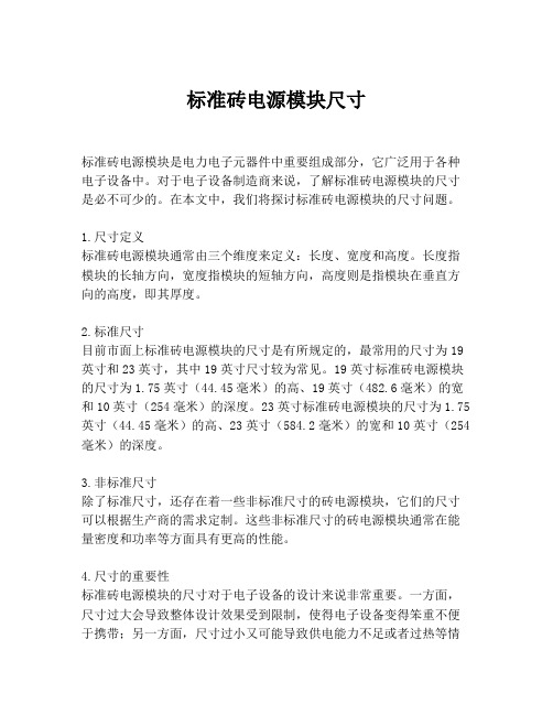
标准砖电源模块尺寸
标准砖电源模块是电力电子元器件中重要组成部分,它广泛用于各种电子设备中。
对于电子设备制造商来说,了解标准砖电源模块的尺寸是必不可少的。
在本文中,我们将探讨标准砖电源模块的尺寸问题。
1.尺寸定义
标准砖电源模块通常由三个维度来定义:长度、宽度和高度。
长度指模块的长轴方向,宽度指模块的短轴方向,高度则是指模块在垂直方向的高度,即其厚度。
2.标准尺寸
目前市面上标准砖电源模块的尺寸是有所规定的,最常用的尺寸为19英寸和23英寸,其中19英寸尺寸较为常见。
19英寸标准砖电源模块的尺寸为1.75英寸(44.45毫米)的高、19英寸(482.6毫米)的宽和10英寸(254毫米)的深度。
23英寸标准砖电源模块的尺寸为1.75英寸(44.45毫米)的高、23英寸(584.2毫米)的宽和10英寸(254毫米)的深度。
3.非标准尺寸
除了标准尺寸,还存在着一些非标准尺寸的砖电源模块,它们的尺寸可以根据生产商的需求定制。
这些非标准尺寸的砖电源模块通常在能量密度和功率等方面具有更高的性能。
4.尺寸的重要性
标准砖电源模块的尺寸对于电子设备的设计来说非常重要。
一方面,尺寸过大会导致整体设计效果受到限制,使得电子设备变得笨重不便于携带;另一方面,尺寸过小又可能导致供电能力不足或者过热等情
况。
5.总结
标准砖电源模块是电子设备制造领域中必不可少的元器件,其尺寸的设计在整个设备的效能和性能上起着重要的作用。
因此,对于电子设备制造商来说,选择合适的标准电源模块尺寸是非常必要的。
- 1、下载文档前请自行甄别文档内容的完整性,平台不提供额外的编辑、内容补充、找答案等附加服务。
- 2、"仅部分预览"的文档,不可在线预览部分如存在完整性等问题,可反馈申请退款(可完整预览的文档不适用该条件!)。
- 3、如文档侵犯您的权益,请联系客服反馈,我们会尽快为您处理(人工客服工作时间:9:00-18:30)。
Z24H28T500NNB DC-DC电源模块
【产品描述】
1. 产品概述
Z24H28T500NNB是标准1/2砖单路隔离稳压输出模块,额定输出电压28V,输出电流17.9A。
峰值效率可达96%,工作温度范围是:-40℃~ +100℃(壳温)。
采用领先预偏值启动同步整流技术提高了电源效率和同步整流的可靠性;
采用有源钳位吸收技术降低了功率MOS管的电压应力,提高功率MOS管的可靠性;
采用无光耦的电压反馈环提高了环路的响应速度与稳定性;
采用主从模块民主均流法,使能模块能共享电流信号完成自动均流并联应用,可应用于高可靠性的冗余备份系统。
采用多层厚铜PCB与平面变压器工艺提高了电源的功率密度;
采用铝外壳灌封工艺提高了电源的抗振动冲击,耐盐雾,耐高温能力。
2. 电气特性
●工作电压范围: 18V ~ 36V (瞬态工作电压50V/1S)
●额定输出功率500W
●工作温度范围是:-40℃~ +100℃(壳温)
●输入输出之间基本绝缘1500Vdc
●模块可并联均流
●固定开关频率PWM控制
●无最小负载限制
3. 控制特性
●控制端子特性(负逻辑)
●输出电压补偿
●输出电压调节范围:50% ~ 110% Vo(Vo为额定输出电压28V)
4. 保护功能
●输入欠压锁死
●输出过流保护
●输出短路保护
●输出过压保护
●过温保护
5. 命名规则
6. 结构尺寸
机械尺寸图单位mm 7. 引脚定义
2 ON/OFF 输出使能端
B +SHARE 并联均流正端(B型功能)
3 -SHARE 并联均流负端(B型功能)
4 -VIN 输入电压负端
5 -VOUT 输出电压负端
6 -SNS 远端采样负端
7 TRIM 输出电压调整端
8 +SNS 远端采样正端
9 +VOUT 输出电压正端
8. 电气特性
输入电容Cin=220uF,输入电压28V,输出电容Cout=220uF,输出28V/500W,环境温度25℃(除非特别提及)。
输入电压恢复点
16.8 17.5 17.8 V 输入电压保护点
15.4 16.0 16.5 V
输入欠压
回差
1.5 V 输入电容 220 470 uF 最大输入电流 30 35 A 输入18V
输入纹波电流 250 300 mA 纹波电流峰峰值,如图9
空载输入电流 220 300 mA 输入电压28V 禁止输入电流
16
20
mA
输入电压28V ,使能关机
50% ~ 75% ~ 50% I o,max,
1A/μs
恢复时间200 us
输出电压调节范围-50 +10 %
输出过压保护33 35.8 38 V
上升时间28 ms
5,图7
如图
启动延时时间35 ms
开机瞬态
输出过冲0 5 %V o
9. 典型曲线图
图1:效率与输出负载电流曲线图,外壳温度25℃
图3:输出电流与铝基板温度降额曲线图
图4:输出电压与输出电流曲线图
10. 典型波形
测试条件:输入电容Cin=220uF,输入电压28V,输出电容Cout=220uF,输出28V/500W,环境温度25℃
图5:使能开机波形(负逻辑),1通道为使能控制电平,2通道为输出电压上升波形
图6:使能关机波形(负逻辑),1通道为使能控制电平,2通道为输出电压下降波形
图7:输入电压开机波形,1通道输入电压波形,2通道为输出电压上升波形
图8:输入电压关机波形,1通道输入电压波形,2通道为输出电压下降波形
图9:输入电流纹波,输入28V,输入端电容Cin=220uF,输出28V/500W
图10:输出电压纹波,输入28V,输出28V/500W,输出电容Cout=220uF。
示波器带宽20MHZ,示波器探头外接0.1uF陶瓷电容与10uF电解电容。
图11: 1通道输出脉冲电流波形,2通道输出电压动态波形
输出电容Cout=220uF,负载25%-50%-25%变化,脉冲负载频率500HZ,di/dt=1A/us.
图12: 1通道输出脉冲电流波形,2通道输出电压动态波形
输出电容Cout=220uF,负载50%-75%-50%变化,脉冲负载频率500HZ,di/dt=1A/us.
图12: 1通道输出脉冲电流波形,2通道输出电压动态波形
输出电容Cout=220uF,负载0%-100%-0%变化,脉冲负载频率500HZ,di/dt=1A/us. 【应用注释】
11. 典型应用
无并联均流功能的单电源接线图
电源输入端需要加入滤波器满足电磁兼容要求
Cin为输入电容,容值等于470uF,耐压不低于50V.推荐使用470UF/100V电容
Cout为输出电容,推荐使用470UF/50V电容
Rtrim-up与Rtrim-down分别为输出电压上调电阻与输出电压下调电阻(具体阻值算法参考10页),不需要调压功能时悬空Trim脚。
电源并联均流接线图
为提高系统电源的可靠性和输出功率,需要多电源并联均流,采用民主的主从均流法,使电源在并联后通过连接Share实现自动均流,输出电流大的电源为主模块,均流精度为±5%,并联电源的输出功率基本相等。
在选用具有并联均流版本电源时,电源可以采用上图接线实现并联均流应用。
Share为并联均流母线脚,U1为光耦,控制并联电源同时启动,也可将使能控制端短接到输入负不做控制,控制线应尽量远离电源的干扰。
在进行调压应用是,模块分别单独进行调压。
L1输出共模电感,电源在并联时,防止互相干扰影响电源正常工作,需要加入输出共模电感,也可以在输出正端和负端都穿入差模电感。
12. 使能控制
Z24H28T500NNB 逻辑电平兼容CMOS和TTL电平。
ON/OFF脚和Vin-脚之间的电压请不要超过“绝对最大值”表中的范围以确保正确的操作。
外部远程开关电路推荐图13所示电路。
光耦隔离式远程开关电路非隔离式远程开关电路
图13 外部远程开关电路
13. 调节输出电压
上调输出电压下调输出电压
Rtrim-up =5.1(Vout-Δ)/(Δ-1.225) ; Δ=1.225Vout/Vo Rtrim-down =5.1Δ/(1.225-Δ); Δ=1.225Vout/Vo
Rtrim-up单位为KΩ, Vout为需要上调到的输出电压Rtrim-down单位为KΩ, Vout为需要下调到的输出电压
Vo=28V
14. 筛选试验
4 外部目检GJB 548B方法2009.1 ●。
