国外原装进口电化学氢气传感器H2-M-4000
Honeywell HIH-4000 系列 湿度 测湿传感器 说明书

湿度/测湿传感器测湿传感器HIH-4000系列特点热固塑料外壳相对于RH%(相对湿度)值的线性电压输出激光调整互换性低功率设计高精度快速响应时间稳定,漂移小抗化学性典型的应用制冷设备采暖、通风空调设备医用设备干燥设备测量设备电池供电系统原始设备制造厂(OEM)组装件HIH-4000系列测湿传感器是专为大量生产的原始设备制造厂(OEM)用户而设计的。
利用这传感器的线性电压输出可直接输入到控制器或其他装置。
一般仅需取出200μA电流,HIH-4000系列测湿传感器就能理想地用于低引出、电池供电系统。
传感器良好的互换性减少或消除了OEM的生产校验成本。
可以提供单个传感器校准数据。
HIH-4000系列测湿传感器作为一个低成本、可软焊的单个直插式组件(SIP)提供仪表测量质量的相对湿度(RH)传感性能。
RH传感器可用在二引线间有间距的配量中,它是一个热固塑料型电容传感元件,其芯片内具有信号处理功能。
传感元件的多层结构对应用环境的不利因素,诸如潮湿、灰尘、污垢、油类和环境中常见的化学品具有最佳的抗力。
表1:性能规格在5.0 VDC供电电压和25°C时,除非另有规定%RH性能规格包括试验系统测量误差(±0.5%的典型值)参数最小值典型值最大值单位互换性(最佳配合直线)%RH0至60%RH-5 5%RH60%至100%-8 8互换性(二阶曲线)%RH±3.5%RH*精度(最佳配合直线)±3.5%RH**精度电压输出(二阶曲线)±2.5%RH 滞后性 3%RH重复精度±0.5整定时间70mSSec响应时间l/e指在缓慢流动的空气中15***稳定性(在1年内50%RH 的条件下)%RH±1.2****稳定性(50%RH条件下 ) %RH供电要求TBDVDC5.8供电电压 4μA供电电流500电压输出(一阶配合) V输出=V供电(0.0062(传感器RH)+0.16)电压输出(二阶曲线配合) V输出= 0.00003 (传感器RH)2 + 0.0281 (传感器RH) +0.820,在25°C时的典型数据温度补偿V输出=(0.0305+0.000044T-0.0000011T2) (传感器RH)+ (0.9237-0.0041T+0.000040T2)T=温度单位为°C工作温度-40 见图1 85 °C°F-40 185工作湿度 0见图1 100 %RH储存温度°C-40 125°F-40 257储存湿度见图2 %RH* 仅对HIH-400-003和-004型号而言。
瑞士猛巴宝大量程氢气传感器H2-CT-40000

ELECTROCHEMICAL GAS SENSORSREV.: 8/2010 Page 1 of 1 SPECIFICATION SHEET FOR H2 SENSOR TYPE H2/CT-40000 PERFORMANCE CHARACTERISTICSCROSS-SENSITIVITY DATAInterfering Gas Cross-Sensitivity (%)CO < 20Performance data conditions:20 °C, 50% RH and 1013 mbarAPPLICATIONSSafety and Environmental ControlPHYSICAL CHARACTERISTICSBOTTOM VIEWSIDE VIEWCompact-Size Outline DimensionsThe data contained in this document is for guidance only. Membrapor AG accepts no liability for any consequential losses, injury or damage resulting from the use of this document or the information contained within it. The data is given for guidance only. Customers should test under their own conditions, to ensure that the sensors are suitable for their own requirements.Nominal Range 0 – 40’000 ppmMaximum Overload 50’000 ppmExpected Operation Life 2 years in airOutput Signal 5.5 ± 2 nA/ppmResolution 10 ppmTemperature Range 0 °C to 55 °CPressure Range Atmospheric ± 10%Pressure Coefficient No dataT90 Response Time < 45 secRelative Humidity Range 50 % to 95 % R.H.non-condensingTypical Baseline Range (pureair, 20°C)-60 to + 60 ppmMaximum Zero Shift (+20°Cto +40°C)70 ppmLong Term Output Drift < 2% signal loss/monthRecommended Load Resistor 10 OhmBias Voltage Not requiredRepeatability 2 % of signalOutput Linearity LinearWeight ~ 13 gPosition Sensitivity NoneStorage Life Six months incontainerRecommended StorageTemperature5 °C – 20 °CWarranty Period 12 months from dateof dispatch深圳市深国安电子科技有限公司地址:广东省深圳市龙华新区牛栏前大厦C507电话:86 755-85258900 网址:www.singoan.com www.singoan.com.cn www.shenguoan.com 。
氢气传感器
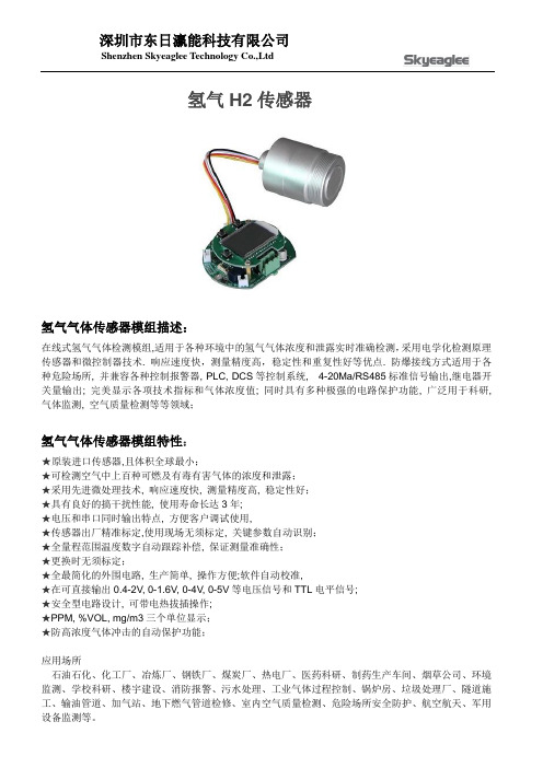
氢气H2传感器氢气气体传感器模组描述:在线式氢气气体检测模组,适用于各种环境中的氢气气体浓度和泄露实时准确检测,采用电学化检测原理传感器和微控制器技术. 响应速度快,测量精度高,稳定性和重复性好等优点. 防爆接线方式适用于各种危险场所, 并兼容各种控制报警器, PLC, DCS等控制系统, 4-20Ma/RS485标准信号输出,继电器开关量输出; 完美显示各项技术指标和气体浓度值; 同时具有多种极强的电路保护功能, 广泛用于科研, 气体监测, 空气质量检测等等领域;氢气气体传感器模组特性:★原装进口传感器,且体积全球最小;★可检测空气中上百种可燃及有毒有害气体的浓度和泄露;★采用先进微处理技术, 响应速度快, 测量精度高, 稳定性好;★具有良好的搞干扰性能, 使用寿命长达3年;★电压和串口同时输出特点, 方便客户调试使用,★传感器出厂精准标定,使用现场无须标定, 关键参数自动识别;★全量程范围温度数字自动跟踪补偿, 保证测量准确性;★更换时无须标定;★全最简化的外围电路, 生产简单, 操作方便;软件自动校准,★在可直接输出0.4-2V, 0-1.6V, 0-4V, 0-5V等电压信号和TTL电平信号;★安全型电路设计, 可带电热拔插操作;★PPM, %VOL, mg/m3三个单位显示;★防高浓度气体冲击的自动保护功能;应用场所石油石化、化工厂、冶炼厂、钢铁厂、煤炭厂、热电厂、医药科研、制药生产车间、烟草公司、环境监测、学校科研、楼宇建设、消防报警、污水处理、工业气体过程控制、锅炉房、垃圾处理厂、隧道施工、输油管道、加气站、地下燃气管道检修、室内空气质量检测、危险场所安全防护、航空航天、军用设备监测等。
注意事项:气体传感器模组设计七只管脚, 采用插拔方式安装在传感器插座上, 为保证连接可靠应当选择使用专插孔.插孔应当按管脚对应方式布置, 插孔应当垂直安装, 焊接牢固.根据用户的特殊要求, 可以不使用管脚拔插方式, 而采用外部引线方式, 引线型号为ZR-BVR0.75, 线长一般不超过150mm. 在非防爆场所, 可以带电热插拔. 在有防爆要求的工作现场, 安装前必须关闭传感器所连接设备的电源.。
美国H2SCAN公司-产品手册
充电时间<4小时 0℃~45℃
存储温度 环境参数
相对湿度
-20℃~45℃ 0%~95% RH
校准环境
空气
重量
975g
长宽厚(cm)
17.3×8.6×3.6
外形尺寸 其它
传感器 长度:19.8cm
可伸缩电缆 缩进长度:66.0cm
探头直径:1.3cm 延伸长度:182.9cm
手柄直径:3.0cm 直径:1.8cm
电镀铬工艺
变压器油
铅酸蓄电池监测
燃料电池技术/汽车行业
半导体和电子制造业
氢气加气站
重要设备制造商
车辆废气分析
工业和消费品制造商
燃料电池车辆
尾气排放装置
科研机构及大学
化工和制药行业
2
Model 500手持式氢气检漏仪
特性
量程:15ppm~100%(体积) 氢气专一性,抗其它气体干扰 快速响应 嵌入式电池;系统可独立操作 LED指示灯,泄漏报警可视化 12毫米小型传感器探头 自动复位功能可避免反复校准 使用寿命:10年 CE认证 可选1500本质安全型(ATEX)
技术优点
1、氢气专一性技术,抗其它气体干扰 2、钯镍(Pd-Ni)合金敏感薄膜保证传感器氢气专一性和高稳定性 3、独特的涂层确保传感器在恶劣的环境(湿Cl2和含S介质等)中连续测量 4、内部温度控制回路为外部气体介质温度波动做补偿 5、独特的氢气敏感原理,可以在N2,O2和其它惰性气体中工作
日本NEMOTO电化学硫化氢气体传感器NE-H2S(中文)
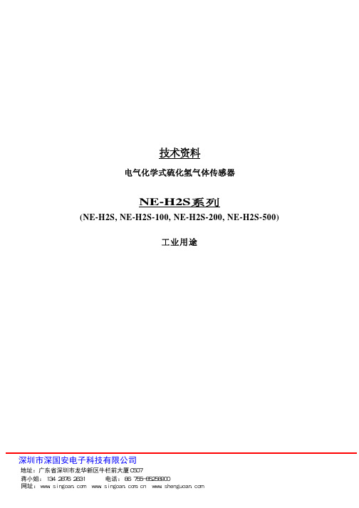
技术资料电气化学式硫化氢气体传感器NE-H2S系列(NE-H2S, NE-H2S-100, NE-H2S-200, NE-H2S-500) 工业用途深圳市深国安电子科技有限公司地址:广东省深圳市龙华新区牛栏前大厦C507 蒋小姐:134 2876 2631 电话:86 755-85258900 网址:www.singoan.com www.singoan.com.cn www.shenguoan.com1. 概述 Nemoto NE 系 列 传 感 器 是 用 于 工 业 用 途 的 传 感 器 .NE-H2S, NE-H2S-100, NE-H2S-200 和 NE-H2S-500 是 用 于 检 测 硫 化 氢 的 气 体 传 感 器 . 外 形 , 脚 位 和 基 本 特 性 与 其 他 型 号 兼 容,尤其是 NE-H2S-100 在基本特性等方面的兼容度非常高。
另外,这些传感器与其他 传感器相比具有更好的稳定性,重复再现性,耐用性和可靠性,而价格具有竞争力。
特性和应用描述如下。
2. 检测原理 电化学式气体传感器由根据发生氧化反应的检知电极,与此同时发生还原反应的对向电极和用 来监视和平衡持续电压的参照电极组成。
下图是电化学式传感器NE-H2S的结构, 硫化氢气体通 过传感器的隔膜扩散进入工作电极,在工作电极端产生氧化。
因此反应产生的质子进入对向电 极,在电解液中与溶解氧发生反应变成水。
整个反应过程如上。
硫化氢气体浓度与通过连续反 应成产生的电流成比率关系。
3. 特性 快速反应 良好选择性和重复性 良好线性输出和稳定性 高可靠性和使用寿命 高温高湿环境下良好的耐用性 4. 检测气体 硫化氢 5. 用途 工业H2S气体浓度显示计 用于工业设备的H2S气体报警器 手持式H2S气体泄露检测仪 环境监测设备 6. 尺寸和外观深圳市深国安电子科技有限公司地址:广东省深圳市龙华新区牛栏前大厦C507 蒋小姐:134 2876 2631 电话:86 755-85258900 网址:www.singoan.com www.singoan.com.cn www.shenguoan.com外壳材枓 壳体颜色 重量PPO 黄色 约5克 图1 NE-H2S的外观和尺寸 (其他H2S系列与上面相同)7. 额定值 1) 使用时周围温湿度 2) 贮存时推荐的周围温湿度 3) 使用时压力范围 4) 检测范围 型号 温度 : -20 - +50 攝氏度 湿度 : 15 – 90%RH 温度 : 0 – 20 攝氏度 湿度 : 15 – 90%RH 0.9 – 1.1 atm 检测范围 最大负荷深圳市深国安电子科技有限公司地址:广东省深圳市龙华新区牛栏前大厦C507 蒋小姐:134 2876 2631 电话:86 755-85258900 网址:www.singoan.com www.singoan.com.cn www.shenguoan.comNE-H2S NE-H2S-100 NE-H2S-200 NE-H2S-500 5) 推荐的载荷电阻0 – 100ppm 0 – 100ppm 0 – 200ppm 0 – 500ppm500ppm 500ppm 1,000ppm 2,000ppm 10 ohm8. 规格参数 1) 输出信号(20 攝氏度时) NE-H2S NE-H2S-100(标准型号) NE-H2S-200 NE-H2S-500 2) 反应时间(T90) 3) 同一天的重复再现性 4) 年零点偏移值 NE-H2S, 100 和 200 NE-H2S-500 500 +/- 100nA/ppm.H2S 700 +/- 150nA/ppm.H2S 500 +/- 100nA/ppm.H2S 200 +/- 50nA/ppm.H2S 小于30秒. 小于+/- 2% 小于1ppm硫化氢 小于2ppm硫化氢 小于1ppm硫化氢 小于3ppm硫化氢 小于10%/年 24个月 小于6个月5) 零点偏移的温度依赖性 NE-H2S, 100 和 200 NE-H2S-500 6) 长期灵敏度衰减性 7) 保证寿命 8) 建议贮存时间 9. 电气特性 9-1. 典型气体灵敏度9-2. 交叉灵敏度图2 : NE-H2S系列的气体灵敏度 表格1 : NE-H2S系列的交叉灵敏度深圳市深国安电子科技有限公司地址:广东省深圳市龙华新区牛栏前大厦C507 蒋小姐:134 2876 2631 电话:86 755-85258900 网址:www.singoan.com www.singoan.com.cn www.shenguoan.com检测气体 硫化氢 一氧化碳 二氧化碳 氢气 氯气 二氧化硫 氧化在氮 甲烷 氨气 二氧化氮 乙烯 *曝光时间 *相应灵敏度 (H2S是100的相应灵敏度) NE-H2S, NE-H2S-200 100 小于2 0 小于1 0 小于13 小于5 0 0 -20 约0 30 秒 NE-H2S-100 100 小于3 0 小于1 0 小于20 小于4 0 0 -30 约0 NE-H2S-500 100 小于5 0 小于2 0 小于23 小于3 0 0 -30 约09-3. 温度依赖性图3 : NE-H2S的的典型温度系数 (100 在20 攝氏度时)深圳市深国安电子科技有限公司地址:广东省深圳市龙华新区牛栏前大厦C507 蒋小姐:134 2876 2631 电话:86 755-85258900 网址:www.singoan.com www.singoan.com.cn www.shenguoan.comTypical图4 : NE-H2S-100, NE-H2S-200的温度依赖性Typical图5 : NE-H2S-500的温度依赖性 9-4. 反应和回复特性图g.6 : NE-H2S的反应和回复特性 (20攝氏度时)深圳市深国安电子科技有限公司地址:广东省深圳市龙华新区牛栏前大厦C507 蒋小姐:134 2876 2631 电话:86 755-85258900 网址:www.singoan.com www.singoan.com.cn www.shenguoan.com9-6. 长期稳定性 常规环境下3年时间内都非常稳定.图7 : 常规环境NE-H2S的长期稳定性 10. 耐用性 NE-H2S在如高温高湿或高温干燥等严格环境下非常耐用. 特性描述如下. 10-1. 高温耐用性图8 : 高温干燥环境下的耐用性(80攝氏度) 10-2. 高温高湿耐用性图9 : 高温高湿环境下的耐用性(60攝氏度 90%RH)深圳市深国安电子科技有限公司地址:广东省深圳市龙华新区牛栏前大厦C507 蒋小姐:134 2876 2631 电话:86 755-85258900 网址:www.singoan.com www.singoan.com.cn www.shenguoan.com10-3. 低温耐用性图10 : 低温耐用性(-20攝氏度) 10-4. 热冲击实验 测试条件 传感器分別在零下-20攝氏度的环境下和50攝氏度的环境下贮存30分钟, 重复循环10次. 表格3. 热冲击实验 测试后(micro A)空气中零点漂移100ppm H2S的灵敏度测试前(micro A) No. 1 2 3 4 5空气中零点漂移灵敏度变化比率100ppm H2S的灵敏度(%) 100.0 99.8 99.8 99.6 100.20.01 0.01 0.01 0.01 0.0156.2 54.1 56.9 54.3 55.80.02 0.03 0.03 0.03 0.0256.2 54.0 56.8 54.1 55.910-5. 落地实验 测试条件 传感器从1米高处自由落体跌落至混凝土地板5次. 表格4. 落地实验 测试后(micro A)空气中零点漂移100ppm H2S的灵敏度测试前(micro A) No. 1 2 3空气中零点漂移灵敏度变化比率100ppm H2S的灵敏度(%) 100.2 99.8 100.40.03 0.03 0.0255.4 56.5 54.70.03 0.03 0.0455.5 56.4 54.910-6. 干扰气体下的暴露实验 A. SO2气体暴露实验 测试条件 常温常湿环境中在500ppm的二氧化硫下传感器暴露2小时。
氢气传感器现状分析报告
氢气传感器现状分析报告1. 引言氢气是一种常见的工业气体,在许多行业中被广泛使用。
然而,氢气的易燃性和爆炸性使其在生产和使用过程中存在一定的安全隐患。
为了保障人员和设备的安全,氢气传感器被广泛应用于氢气检测和监测中。
本报告将对氢气传感器的现状进行分析。
2. 氢气传感器的原理氢气传感器通常基于电化学和热导传感原理进行工作。
电化学传感器通过测量氢气与电极之间的电流变化来检测氢气的浓度。
热导传感器则通过测量氢气导热性能的变化来实现氢气浓度的检测。
3. 氢气传感器的类型氢气传感器按照工作原理可以分为电化学传感器、热导传感器和半导体传感器等几种类型。
其中,电化学传感器具有灵敏度高、精度高的特点,但需要定期更换电极,经常校准以保持准确性。
热导传感器具有响应速度快和抗干扰能力强的特点,但对温度变化敏感。
半导体传感器则以其成本低、结构简单等优点在特定应用领域得到广泛应用。
4. 氢气传感器的市场应用氢气传感器在许多行业中得到广泛应用。
主要应用领域包括氢气发电、燃料电池车辆、氢气储存和输送等。
在氢气发电中,氢气传感器用于监测氢气浓度,以确保燃烧过程的安全性。
在燃料电池车辆中,氢气传感器用于监测氢气泄漏,保障乘客的安全。
此外,氢气传感器也在氢气储存和输送领域有重要应用,以对氢气泄漏进行及时检测。
5. 氢气传感器的发展趋势随着氢能技术的不断发展,氢气传感器正面临着许多挑战和机遇。
传感器的灵敏度、准确性和稳定性是发展的重中之重。
同时,还需要提高传感器的响应速度和抗干扰能力。
未来的氢气传感器可能会更加智能化,并具备无线通讯功能,方便与其他设备进行实时数据交互。
6. 结论氢气传感器在氢能行业中发挥着重要的作用。
不同类型的氢气传感器适用于不同的应用场景。
目前,传感器的性能仍有待提高,但随着氢能技术的进一步发展,信任和重视传感器的作用将会更加突出。
我们对氢气传感器有信心,相信它将在氢能领域的安全监测和控制中发挥越来越重要的作用。
氢气检测仪 原理
氢气检测仪原理氢气检测仪是一种用于检测环境中氢气浓度的仪器。
它的原理主要基于氢气的特性和传感器技术。
下面我将详细介绍氢气检测仪的原理。
首先,氢气是一种无色、无味、无毒的气体,在环境中常以分子形式存在。
而高浓度的氢气可导致爆炸和火灾等危险情况,因此对氢气浓度的检测非常重要。
氢气检测仪一般采用氢气传感器来感知氢气浓度。
常见的氢气传感器有氢气敏感电化学传感器、催化燃烧传感器和半导体传感器等。
不同的传感器原理略有不同,下面将依次介绍。
首先,氢气敏感电化学传感器是一种基于电化学反应原理的传感器。
它由电极、电解质和敏感层组成。
当氢气进入传感器后,氢气与电解质反应产生电荷,进而引发电化学反应。
传感器测量电极上的电流变化,由此判断氢气浓度的变化。
其次,催化燃烧传感器是一种基于氢气催化燃烧原理的传感器。
它由催化剂和热电偶组成。
当氢气进入传感器时,氢气与催化剂发生催化燃烧反应,产生热量。
传感器测量热电偶的温度变化,由此判断氢气浓度的变化。
再次,半导体传感器是一种基于半导体材料电导率变化原理的传感器。
它由半导体材料和电路组成。
当氢气进入传感器后,氢气与半导体材料发生化学反应,改变半导体材料的电导率。
传感器测量电路上的电压变化,由此判断氢气浓度的变化。
不同类型的氢气检测仪适用于不同的场景和要求。
例如,氢气敏感电化学传感器的优点是响应速度快、灵敏度高,适用于氢气浓度较低的环境下;催化燃烧传感器的优点是结构简单、使用寿命长,适用于氢气浓度较高的环境下;半导体传感器的优点是价格低廉、体积小巧,适用于氢气浓度一般的环境下。
除了传感器,氢气检测仪还包括数据处理部分和显示部分。
数据处理部分通常由微处理器、ADC(模数转换器)和存储器组成。
它负责对传感器采集到的原始信号进行处理和分析,得到准确的氢气浓度值。
显示部分通常由液晶显示屏、报警灯和声音报警器组成。
它负责将检测结果进行显示和报警,以便用户及时采取安全措施。
总的来说,氢气检测仪的原理主要基于氢气传感器和数据处理技术。
氢气浓度传感器是什么?
氢气浓度传感器是什么?氢气浓度传感器在常温下对氢气非常敏感且具有很好的选择性,可以作为检测环境中氢气浓度的传感器,出于生产生活中对安全的要求,快速、灵敏的氢气传感器是十分必要的,能够及时避免爆炸的可能性。
下面随小编去了解下氢气浓度传感器。
一、氢气浓度传感器分类1、半导体型传感器以电阻型半导体传感器为例:主要以sno2,zno,wo3等金属氧化物为气敏材料,例如:国产qm系列氢气传感器就是以sno2作为氢气敏感材料,故也称金属氧化物半导体氢气传感器。
其工作原理是:当吸附氢气后,氢气作为施主释放出电子,与化学吸附层中的氧离子结合,于是载流子浓度发生变化,该变化值与氢气体积分数存在一定的函数关系。
2、热电型传感器首先,在基片上沉积一层热电材料,然后,在热电材料表面的某一部分沉积一层催化金属,如,pt,pd等,最后,分别在催化金属层、热电薄膜层(表面上无催化金属)引出电极,即获得最为简单的热电型氢气敏感元件。
当此敏感元件暴露在含氢气的环境中在催化金属的,作用下,氢气与氧气反应生成水蒸汽并放出热量,于是,沉积有催化金属的一端温度高,为热端,无催化金属的一端温度低,为冷端,由于热电材料的热电发电效应(seebeck效应),将这种热端与冷端之间的温差转换为温差电势,以电信号的形势输出,从而实现对氢气的检测。
3、光纤传感器由于多种固态氢气传感器使用的都是电信号,一个共同的弊端就是可能产生电火花,对于氢气体积分数较高的环境来说存在极大的安全隐患。
而光纤传感器使用的是光信号,所以,适用于易爆炸的危险环境。
二、氢气浓度传感器应用钢厂电池系统变压器维护氢气报警器氢气的探测领域三、氢气浓度传感器地位氢气由于其燃烧效率高、产物无污染等优点,与太阳能、核能一起被称为三大新能源。
作为一种新能源,氢气在航空、动力等领域得到广泛的应用;同时,氢气作为一种还原性气体和载气,在化工、电子、医疗、金属冶炼,特别在军事国防领域有着极为重要的应用价值。
美国英思科MX4多种气体检测仪
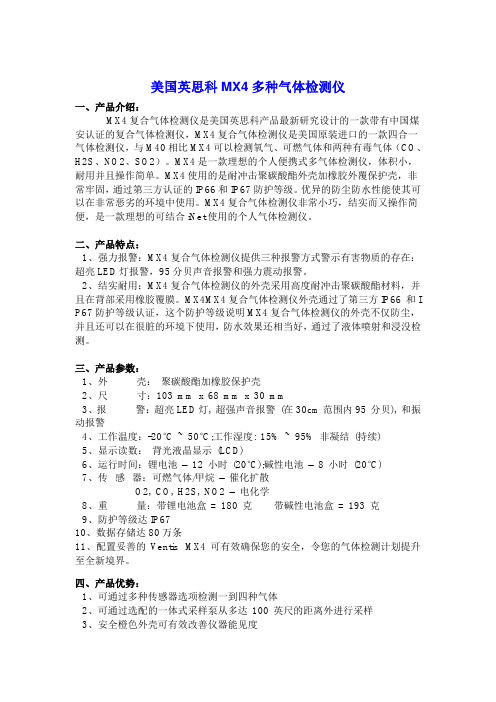
美国英思科MX4多种气体检测仪一、产品介绍:MX4复合气体检测仪是美国英思科产品最新研究设计的一款带有中国煤安认证的复合气体检测仪,MX4复合气体检测仪是美国原装进口的一款四合一气体检测仪,与M40相比MX4可以检测氧气、可燃气体和两种有毒气体(CO、H2S、NO2、SO2)。
MX4是一款理想的个人便携式多气体检测仪,体积小,耐用并且操作简单。
MX4使用的是耐冲击聚碳酸酯外壳加橡胶外覆保护壳,非常牢固,通过第三方认证的IP66和IP67防护等级。
优异的防尘防水性能使其可以在非常恶劣的环境中使用。
MX4复合气体检测仪非常小巧,结实而又操作简便,是一款理想的可结合iNet使用的个人气体检测仪。
二、产品特点:1、强力报警:MX4复合气体检测仪提供三种报警方式警示有害物质的存在:超亮LED灯报警,95分贝声音报警和强力震动报警。
2、结实耐用:MX4复合气体检测仪的外壳采用高度耐冲击聚碳酸酯材料,并且在背部采用橡胶覆膜。
MX4MX4复合气体检测仪外壳通过了第三方IP66 和I P67防护等级认证,这个防护等级说明MX4复合气体检测仪的外壳不仅防尘,并且还可以在很脏的环境下使用,防水效果还相当好,通过了液体喷射和浸没检测。
三、产品参数:1、外壳:聚碳酸酯加橡胶保护壳2、尺寸:103 mm x 68 mm x 30 mm3、报警:超亮LED灯, 超强声音报警(在30cm范围内95 分贝), 和振动报警4、工作温度:-20°C ~ 50°C;工作湿度: 15% ~ 95% 非凝结(持续)5、显示读数:背光液晶显示(LCD)6、运行时间:锂电池–12 小时(20°C);碱性电池–8 小时(20°C)7、传感器:可燃气体/甲烷–催化扩散O2, CO, H2S, NO2 –电化学8、重量:带锂电池盒= 180 克带碱性电池盒= 193 克9、防护等级达IP6710、数据存储达80万条11、配置妥善的Ventis MX4 可有效确保您的安全,令您的气体检测计划提升至全新境界。
氢气检测仪工作原理

氢气检测仪工作原理
氢气检测仪的工作原理是基于氢气的化学反应或物理特性进行测量。
以下是几种常见的氢气检测仪的工作原理:
1. 火焰离子化检测器(FID):FID使用氢气的可燃性来检测
其浓度。
当氢气进入FID时,通过与空气中的氧气混合并点燃,产生一个火焰。
氢气在火焰中燃烧时会产生离子,这些离子在电场的作用下会产生电流。
测量电流的强度可以用来确定氢气的浓度。
2. 电化学传感器:电化学传感器使用化学反应来检测氢气。
这种传感器通常包含一个阳极和一个阴极,它们之间通过电解质或电解池分隔。
当氢气进入传感器时,氢气会通过一系列化学反应与阴极反应产生电流。
测量电流的变化可以确定氢气的浓度。
3. 热导检测器:热导检测器使用氢气的热导率差异来检测浓度。
当氢气进入热导检测器时,氢气会带走热量,导致环境温度下降。
热导检测器通过测量温度的变化来确定氢气浓度。
4. 金属氢感应器:金属氢感应器使用氢气与金属之间的化学反应来检测其浓度。
当氢气接触金属时,氢气会渗透到金属晶格中。
这会导致金属的电阻发生变化,从而可以通过测量金属电阻的变化来确定氢气浓度。
这些是常见的氢气检测仪的工作原理,每种检测仪的具体原理
和结构可能略有不同,但都是基于测量氢气的化学或物理性质来检测其浓度。
氢气检测仪原理

氢气检测仪原理氢气检测仪是一种用于检测氢气浓度的仪器,广泛应用于石化、电力、煤矿等行业中。
它能够检测到氢气浓度并发出警报,以保障现场工作人员的安全。
本文将介绍氢气检测仪的原理及其工作过程。
一、氢气检测仪的原理氢气检测仪的原理是基于氢气与某些化学物质发生反应,产生电化学反应的特性。
当氢气进入检测仪内部时,它会与检测仪中的化学物质发生反应,产生电化学反应,从而生成电流信号。
根据电流信号的大小,可以计算出氢气的浓度。
氢气检测仪通常采用半导体传感器或电化学传感器作为检测元件。
半导体传感器是一种基于电阻变化的传感器,当氢气浓度变化时,它的电阻值也会随之变化。
电化学传感器则是一种基于电化学反应的传感器,当氢气进入传感器时,会与传感器中的电解液发生反应,从而产生电流信号。
二、氢气检测仪的工作过程氢气检测仪的工作过程可以分为三个步骤:检测、处理和显示。
检测:当氢气进入检测仪时,它会与检测仪中的传感器发生反应,产生电流信号。
传感器将电流信号转换为电压信号,并将其发送到处理器。
处理:处理器会对电压信号进行处理,并将其转换为氢气的浓度。
处理器还会根据设定的警报阈值,判断氢气浓度是否超过了安全范围。
如果超过了安全范围,处理器会发出警报信号。
显示:处理器将氢气浓度和警报状态显示在仪器屏幕上。
同时,它还会将警报信号发送给外部设备,如声光报警器或控制系统,以便采取相应的措施。
三、氢气检测仪的应用氢气检测仪广泛应用于石化、电力、煤矿等行业中,以保障现场工作人员的安全。
在石化行业中,氢气检测仪常用于氢气压缩机、氢气储罐等设备的监测。
在电力行业中,氢气检测仪常用于发电机组的氢冷却系统监测。
在煤矿行业中,氢气检测仪常用于瓦斯抽采系统的监测。
总之,氢气检测仪是一种非常重要的安全设备,能够及时检测到氢气浓度并发出警报,保障现场工作人员的安全。
本文介绍了氢气检测仪的原理及其工作过程,以及应用场景。
希望能够对读者有所帮助。
湿度传感器 HIH-4000 系列产品说明书

HIH-4000 Series Humidity SensorsDESCRIPTIONThe HIH-4000 Series Humidity Sensors are designed specifically for high volume OEM (Original Equipment Manufacturer) users.Direct input to a controller or other device is made possible by this sensor’s near linear voltage output. With a typical current draw of only 200 μA, the HIH-4000 Series is often ideally suited for low drain, battery operated systems.Tight sensor interchangeability reduces or eliminates OEM production calibration costs. Individual sensor calibration data is available. The HIH-4000 Series delivers instrumentation-quality RH (Relative Humidity) sensing performance in a competitively priced, solderable SIP (Single In-line Package).Available in two lead spacing configurations, the RH sensor is a laser trimmed, thermoset polymer capacitive sensing element with on-chip integrated signal conditioning.The sensing element's multilayer construction provides excellent resistance to most application hazards such as wetting, dust, dirt, oils and common environmental chemicals.FEATURES•Molded thermoset plastic housing •Near linear voltage output vs % RH •Laser trimmed interchangeability •Low power design •Enhanced accuracy•Fast response time•Stable, low drift performance •Chemically resistant POTENTIAL APPLICATIONS•Refrigeration equipment•HVAC (Heating, Ventilation and Air Conditioning) equipment•Medical equipment•Drying•Metrology•Battery-powered systems•OEM assembliesHIH-4000 Series2 /sensingTABLE 1. PERFORMANCE SPECIFICATIONS (At 5 Vdc supply and 25 ºC [77 ºF] unless otherwise noted.)Parameter Minimum Typical Maximum Unit Specific Note Interchangeability (first order curve) – – – – – 0% RH to 59% RH -5 – 5 % RH – 60% RH to 100% RH -8 – 8 % RH – Accuracy (best fit straight line) -3.5 – +3.5 % RH 1 Hysterisis – 3 – % RH – Repeatability – ±0.5 – % RH – Settling time – – 70 ms – Response time (1/e in slow moving air) – 15 – s – Stability (at 50% RH) – 1.2 – % RH – Voltage supply 4 – 5.8 Vdc 2 Current supply – 200 500 μA –Voltage output (1storder curve fit) V OUT =(V SUPPLY )(0.0062(sensor RH) + 0.16), typical at 25 ºC Temperature compensation True RH = (Sensor RH)/(1.0546 – 0.00216T), T in ºC Output voltage temperature, coefficient at 50% RH, 5 V– -4 – mV/ºC Operating temperature -40[-40] See Figure 1. 85[185] ºC[ºF] – Operating humidity 0 See Figure 1. 100 % RH 3 Storage temperature -50[-58] – 125[257] ºC[ºF] – Storage humidity See Figure 2. % RH 3 Specific Notes:1. Can only be achieved with the supplied slope and offset. For HIH-4000-003 and HIH-4000-004 catalog listings only.2. Device is calibrated at 5 Vdc and 25 ºC.3. Non-condensing environment.General Notes:• Sensor is ratiometric to supply voltage.• Extended exposure to >90% RH causes a reversible shift of 3% RH.• Sensor is light sensitive. For best performance, shield sensor from bright light.FACTORY CALIBRATION DATAHIH-4000 Sensors may be ordered with a calibration and data printout. See Table 2 and the order guide on the back page.TABLE 2. EXAMPLE DATA PRINTOUTModel HIH-4000-003 Channel 92Wafer 030996M MRP 337313 Calculated values at 5 V V OUT at 0% RH V OUT at 75.3% RH0.826 V 3.198 VLinear output for 3.5% RH accuracy at 25 °C Zero offset Slope RH0.826 V31.483 mV/%RH(V OUT - zero offset)/slope (V OUT - 0.826)/0.0315 Ratiometric response for 0% RH to 100% RH V OUTV SUPPLY (0.1652 to 0.7952)Humidity SensorsFIGURE 2. STORAGE ENVIRONMENT (Non-condensing environment.)100%90%Honeywell Sensing and Control 3HIH-4000 Series4 /sensingHumidity SensorsHoneywell Sensing and Control 5HIH-4000 Series6 /sensingORDER GUIDECatalog Listing DescriptionHIH-4000-001 Integrated circuit humidity sensor, 2,54 mm [0.100 in] lead pitch SIPHIH-4000-002 Integrated circuit humidity sensor, 1,27 mm [0.050 in] lead pitch SIPHIH-4000-003 Integrated circuit humidity sensor, 2,54 mm [0.100 in] lead pitch SIP, calibration and data printout HIH-4000-004 Integrated circuit humidity sensor, 1,27 mm [0.050 in] lead pitch SIP, calibration and data printout HIH-4000-005 Equivalent to HIH-4000-001FURTHER HUMIDITY SENSOR INFORMATIONSee the following associated literature at /sensing:•Product installation instructions•Application sheets:– Humidity Sensor Performance Characteristics– Humidity Sensor Theory and Behavior– Humidity Sensor Moisture and Psychrometrics– Thermoset Polymer-based Capacitive SensorsHumidity Sensors THIS PAGE INTENTIONALLY LEFT BLANK.Honeywell Sensing and Control 7Sensing and Control Honeywell1985 Douglas Drive North Minneapolis, MN 55422 /sensing 009017-4-EN IL50 GLO Printed in USA May 2008© 2008 Honeywell International Inc. All rights reserved.WARNINGMISUSE OF DOCUMENTATION• The information presented in this product sheet is forreference only. Do not use this document as a product installation guide.• Complete installation, operation, and maintenanceinformation is provided in the instructions supplied with each product.Failure to comply with these instructions could result in death or serious injury.WARRANTY/REMEDYHoneywell warrants goods of its manufacture as being free of defective materials and faulty workmanship. Honeywell’sstandard product warranty applies unless agreed to otherwise by Honeywell in writing; please refer to your orderacknowledgement or consult your local sales office for specificwarranty details. If warranted goods are returned to Honeywell during the period of coverage, Honeywell will repair or replace, at its option, without charge those items it finds defective. The foregoing is buyer’s sole remedy and is in lieu of all other warranties, expressed or implied, including those ofmerchantability and fitness for a particular purpose. In no event shall Honeywell be liable for consequential, special, or indirect damages.While we provide application assistance personally, through our literature and the Honeywell web site, it is up to the customer to determine the suitability of the product in the application.Specifications may change without notice. The information we supply is believed to be accurate and reliable as of this printing. However, we assume no responsibility for its use.WARNINGPERSONAL INJURYDO NOT USE these products as safety or emergency stop devices or in any other application where failure of the product could result in personal injury.Failure to comply with these instructions could result in death or serious injury.SALES AND SERVICEHoneywell serves its customers through a worldwide network of sales offices, representatives and distributors. Forapplication assistance, current specifications, pricing or name of the nearest Authorized Distributor, contact your local sales office or:E-mail:*********************Internet: /sensingPhone and Fax: Asia Pacific +65 6355-2828 +65 6445-3033 Fax Europe +44 (0) 1698 481481 +44 (0) 1698 481676 Fax Latin America +1-305-805-8188 +1-305-883-8257 Fax USA/Canada +1-800-537-6945 +1-815-235-6847 +1-815-235-6545 Fax。
2024年氢气传感器市场分析报告
2024年氢气传感器市场分析报告1. 引言氢气传感器是一种用于检测和测量氢气浓度的设备。
它在各个领域中广泛应用,包括化工、能源、环境保护等。
本报告旨在对氢气传感器市场进行全面的分析,包括市场规模、市场趋势、竞争格局等。
2. 市场规模根据市场调研数据,氢气传感器市场在过去几年中呈现稳步增长的趋势。
预计到2025年,全球氢气传感器市场规模将达到XX亿美元。
这主要受到节能减排政策的推动以及氢能源产业的快速发展的影响。
3. 市场趋势3.1 氢能源的兴起氢能源作为一种清洁能源的替代方案正在受到越来越多的关注。
随着氢能源产业的快速发展,对氢气传感器的需求也在增加。
氢气传感器在氢能源生产、储存和使用过程中起着关键的监测作用,因此其市场需求将随着氢能源的兴起而不断增长。
3.2 技术创新随着技术的不断进步,氢气传感器的性能和稳定性也在不断提升。
新一代氢气传感器采用了先进的材料和制造工艺,具有更高的精度、更长的寿命和更强的抗干扰能力。
这些技术创新将推动氢气传感器市场的发展。
3.3 市场竞争格局氢气传感器市场的竞争格局相对较为分散,但主要的厂商集中在欧美地区。
这些厂商在技术研发、产品质量和市场渗透方面具有较大优势。
随着市场的不断扩大,新的竞争者也会进入市场,加剧市场竞争。
4. 市场机遇与挑战4.1 市场机遇随着新能源汽车市场的迅速发展,氢能源汽车作为一种潜力巨大的替代方案受到了政府和消费者的重视。
氢能源汽车的普及将带动对氢气传感器的需求增长,为市场带来巨大机遇。
4.2 市场挑战目前,氢气传感器市场还存在一些挑战。
首先,氢气传感器的制造成本较高,需要进一步降低成本才能推广应用。
其次,技术标准尚未统一,需要建立统一的测试方法和标准,保证产品质量和性能的稳定。
5. 市场前景综上所述,氢气传感器市场具有广阔的发展前景。
随着氢能源产业的快速发展,氢气传感器市场需求将持续增长。
未来几年,市场竞争将更加激烈,厂商需要加大研发投入,提升产品性能和质量,以获得竞争优势。
Oxymitter-4000(氧化锆)

Emerson Process Management在烟气氧量分析仪技术方面,一直处于领先地位。Hagan罗斯蒙特分析公司燃 烧产品的设计前身,很早以来就在该领域设立了其工业标准。罗斯蒙特分析公司将Hagan的专家检测技术与罗斯蒙 特的变送器技术有机地结合在一起,开发了具有突破性变革的新产品Oxymitter 4000。 Oxymitter 4000 将氧化锆锆头和电子变送单元集成到一个独立的、结构紧凑的外壳内。在实际应用中,锆头 可以直接插入烟道,测量烟气中的氧含量,无需另配采样系统。
型号:Oxymitter 4000
订货信息 OXT4A 代码 1 2 3 4 5 6 7 8 9 代码 0 1 2 3 4 5 6 7 8 9 A B 代码 0 1 2 3 4 5 代码 0 1 2 4 5 7 8 代码 11 12 13 Oxymitter4000 直插式氧化锆氧量分析变送器 氧化锆氧量变送器订货说明 1.测量传感器类型 陶瓷扩散元件(美国 ANSI 标准) 带阻火器,陶瓷扩散元件(美国 ANSI 标准) 粉末合金扩散元件(美国 ANSI 标准) 陶瓷扩散元件(欧洲 DIN 标准) 带阻火器,陶瓷扩散元件(欧洲 DIN 标准) 粉末合金扩散元件(欧洲 DIN 标准) 陶瓷扩散元件(日本 JIS 标准) 带阻火器,陶瓷扩散元件(日本 JIS 标准) 粉末合金扩散元件(日本 JIS 标准) 2.锆头插入深度 18 英寸(457 毫米) 18 英寸(457 毫米),带耐磨护套 1 3 英尺(0.91 米) 3 英尺(0.91 米),带耐磨护套 1 6 英尺(1.83 米) 6 英尺(1.83 米),带耐磨护套 1 9 英尺(2.74 米) 9 英尺(2.74 米),带耐磨护套 1 12 英尺(3.66 米) 12 英尺(3.66 米),带耐磨护套 1 15 英尺(4.57 米),带耐磨护套 1 18 英尺(5.49 米),带耐磨护套 1 3.配对法兰规格 不需要配对法兰 初次安装,方形焊接法兰,带螺栓 Model 218 规格的配对法兰 现存 Model 218 支撑挡板 其它规格法兰 2 Model 132 规格的配对法兰 4.氧化锆本体法兰规格 不需要配对法兰 只带锆头法兰(美国 ANSI 标准) 新装旁路管或新装耐磨护套(美国 ANSI 标准) 只带锆头法兰(欧洲 DIN 标准) 新装旁路管或新装耐磨护套(欧洲 DIN 标准) 只带锆头法兰(日本 JIS 标准) 新装旁路管或新装耐磨护套(日本 JIS 标准) 5.电子单元外壳和电气滤波终端 - NEMA 4X,IP66 一体化安装,标准电气滤波终端的 HART 电子板 一体化安装,带瞬时保护电气滤波终端的 HART 电子板 分体安装,标准电气滤波终端的 HART 电子板,需要确定电缆长度 8
氢气传感器NBN40-L2-E2-V1-3G-3D说明书

12R e l e a s e d a t e : 2 0 1 6 -11 -0 7 1 0 : 0 9 Da t e o f i s s u e : 2 0 1 6 -1 1 -0 7 1 9 6 2 6 1 _ e n g . x m lPinoutL+L-13421 BN2 WH3 B U4 BKWire colors in accordance with EN 60947-5-2(brown)(white)(blue)(black)3R e l e a s e d a t e : 2016-11-07 10:09D a t e o f i s s u e : 2016-11-07196261_e n g .x m lInstructionManual electrical apparatus for hazardous areas Device category 3G (nA) for use in hazardous areas with gas, vapour and mist Certificate of ComplianceCE marking ATEX marking ¬ II 3G Ex nA IIC T6 GcThe Ex-related marking can also be printed on the enclosed label.Standards EN 60079-0:2012+A11:2013, EN 60079-15:2010 Ignition protection category "n"Use is restricted to the following stated conditionsG eneralThe apparatus has to be operated according to the appropriate data in the data sheet and in this instruction manual. The data stated in the data sheet are restricted by this operating instruction! The special conditions must be observed!Installation, commissioningLaws and/or regulations and standards governing the use or intended usage goal must be observed. If the Ex-related marking is printed only on the supplied label, then this must be attached in the immediate vicinity of the sensor. The sticking surface for the label must be clean and free from grease. The attached label must be legible and indel-ible, including in the event of possible chemical corrosion.MaintenanceNo changes can be made to apparatus, which are operated in hazardous areas.Repairs to these apparatus are not possible.Special conditionsMaximum operating current I L The maximum permissible load current must be restricted to the values given in the fol-lowing list. High load currents and load short-circuits are not permitted.Maximum operating voltage U BmaxThe maximum permissible operating voltage UB max is restricted to the values in the following list. T olerances are not permissible.Maximum permissible ambient temperature T Umax dependant of the load current I L and the max. operating voltage U Bmax Information can be taken from the following list. at U Bmax =30 V , I L =200 mA 48 °C (118.4 °F) at U Bmax =30 V , I L =100 mA 50 °C (122 °F) at U Bmax =30 V , I L =50 mA 51 °C (123.8 °F) at U Bmax =30 V , I L =25 mA52 °C (125.6 °F)Protection from mechanical danger The sensor must not be exposed to ANY FORM of mechanical danger.Protection from UV light The sensor and the connection cable must be protected from damaging UV-radiation. This can be achieved when the sensor is used in internal areas.Protection against transients Ensure transient protection is provided and that the maximum value of the transient pro-tection (140% of 85 V) is not exceeded.Electrostatic chargeElectrostatic charges must be avoided on the mechanical housing components. Dan-gerous electrostatic charges on the mechanical housing components can be avoided by incorporating these in the equipotential bonding.Material selection accessories When selecting accessories, ensure that the material allows the temperature of the enclosure to rise to up to 70 °C.Plug connectorThe plug connector must not be withdrawn under voltage. The proximity switch is identi-fied as follows: "WARNING - DO NOT SEPARATE WHEN ENERGIZED". With the plug connector disconnected, soiling of the internal area must be prevented.(i.e. the area that is inaccessible when the connector is inserted)4Releasedate:216-11-71:9Dateofissue:216-11-7196261_eng.xml Note This instruction is only valid for products according to EN50281-1-1, valid until 30-September-2008Note the ex-marking on the sensor or on the enclosed adhesive labelInstruction Manual electrical apparatus for hazardous areasDevice category 3DCE markingATEX marking ¬ II 3D IP69K T 107 °C (224.6 °F) XThe Ex-significant identification is on the enclosed adhesive labelStandards EN50281-1-1Protection via housingUse is restricted to the following stated conditionsG eneral The apparatus has to be operated according to the appropriate data in the data sheet and in this instruction manual.The data stated in the data sheet are restricted by this operating instruction! The special conditions must be adhered to! Installation, commissioning Laws and/or regulations and standards governing the use or intended usage goal must be observed.The adhesive label provided must be affixed in the immediate vicinity of the sensor! The surface to which the label is appliedmust be clean, flat and free from grease! The affixed adhesive label must be readable and durable, taking account of the possi-bility of chemical corrosion!Maintenance No changes can be made to apparatus, which are operated in hazardous areas.Repairs to these apparatus are not possible.Special conditionsMaximum operating voltage U Bmax The maximum permissible operating voltage UBmax must be restricted to the values given in the following list. T olerances arenot permitted.Maximum operating current I L The maximum permissible load current must be restricted to the values given in the following list.High load currents and load short-circuits are not permitted.Maximum heating (T emperature rise) dependant of the load current I L and the max. operating voltage U BmaxInformation can be taken from the following list. The maximum surface temperature at maximum ambient temperature is givenin the Ex identification of the apparatus.at U Bmax=30 V, I L=200 mA 22 Kat U Bmax=30 V, I L=100 mA 19 Kat U Bmax=30 V, I L=50 mA 18 Kat U Bmax=30 V, I L=25 mA 17 KProtection from mechanical danger The sensor must not be mechanically damaged.Electrostatic charge Electrostatic charges on the metal housing components must be avoided. Dangerous electrostatic charges on the metal hous-ing components can be avoided by incorporating these components in the equipotential bonding.Sliding contact discharges must be avoided.Plug connector The plug connector must not be disconnected under voltage. The proximity switch is marked as follows: "DO NOT DISCON-NECT UNDER VOLTAGE!" When the plug connector is disconnected the ingress of dirt into the inner areas (i.e. the areas,which are not accessible in the plugged-in condition) must be prevented.The plug connection can only be separated using a tool. This is achieved by using the locking protection V1-Clip (Mountingaccessory from Pepperl + Fuchs).5R e l e a s e d a t e : 2016-11-07 10:09D a t e o f i s s u e : 2016-11-07196261_e n g .x m lNote This instruction is only valid for products according to EN 61241-0:2006 and EN 61241-1:2004 Note the ex-marking on the sensor or on the enclosed adhesive label InstructionManual electrical apparatus for hazardous areas Device category 3DCE marking ATEX marking ¬ II 3D Ex tD A22 IP67 T80°C XThe Ex-relevant identification may also be printed on the accompanying adhesive label.Standards EN 61241-0:2006, EN 61241-1:2004 Protection via housing "tD"Use is restricted to the following stated conditionsG eneralThe apparatus has to be operated according to the appropriate data in the data sheet and in this instruction manual.The maximum surface temperature has been determined in accordance with method A without a dust layer on the equipment.The data stated in the data sheet are restricted by this operating instruction!The special conditions must be adhered to!Installation, commissioningThe statutory requirements, directives and standards applicable to the intended use and application must be observed.The adhesive label provided must be affixed in the immediate vicinity of the sensor! The surface to which the label is applied must be clean, flat and free from grease! The affixed adhesive label must be readable and durable, taking account of the possi-bility of chemical corrosion!MaintenanceNo changes can be made to apparatus, which are operated in hazardous areas.Repairs to these apparatus are not possible.Special conditionsMaximum operating current I L The maximum permissible load current must be restricted to the values given in the following list.High load currents and load short-circuits are not permitted.Maximum operating voltage U Bmax The maximum permissible operating voltage UBmax must be restricted to the values given in the following list. T olerances are not permitted.Maximum permissible ambient tempera-ture T Umaxdependant of the load current I L and the max. operating voltage U Bmax Information can be taken from the following list. at U Bmax =30 V , I L =200 mA 48 °C (118.4 °F) at U Bmax =30 V , I L =100 mA 50 °C (122 °F) at U Bmax =30 V , I L =50 mA 51 °C (123.8 °F) at U Bmax =30 V , I L =25 mA52 °C (125.6 °F)Protection from mechanical danger The sensor must not be exposed to ANY FORM of mechanical danger.Protection from UV light The sensor and the connection cable must be protected from damaging UV-radiation. This can be achieved when the sensor is used in internal areas.Electrostatic chargeElectrostatic charges on the metal housing components must be avoided. Dangerous electrostatic charges on the metal hous-ing components can be avoided by incorporating these components in the equipotential bonding.Sliding contact discharges must be avoided.Plug connectorThe plug connector must not be withdrawn under voltage. The proximity switch is identified as follows: "WARNING - DO NOT SEPARATE WHEN ENERGIZED". With the plug connector disconnected, soiling of the internal area must be prevented.(i.e. the area that is inaccessible when the connector is inserted) The plug connection can only be separated using a tool.This is achieved by using the locking protection V1-Clip (Mounting accessory from Pepperl + Fuchs).6Releasedate:216-11-71:9Dateofissue:216-11-7196261_eng.xml Instruction Manual electrical apparatus for hazardous areasDevice category 3D for use in hazardous areas with combustible dustCertificate of ComplianceCE markingATEX marking ¬ II 3D Ex tc IIIC T80°C DcThe Ex-related marking can also be printed on the enclosed label.Standards EN 60079-0:2012+A11:2013, EN 60079-31:2014Protection by enclosure "tc" Some of the information in this instruction manual is morespecific than the information provided in the datasheet.G eneral The corresponding datasheets, declarations of conformity, EC-type examination certifi-cates, certifications, and control drawings, where applicable (see datasheets), form anintegral part of this document. These documents can be found at www.pepperl-. The maximum surface temperature of the device was determined without alayer of dust on the apparatus. Some of the information in this instruction manual is morespecific than the information provided in the datasheet.Installation, commissioning Laws and/or regulations and standards governing the use or intended usage goal mustbe observed. If the Ex-relevant identification is printed exclusively on the adhesive labelprovided, this label must be affixed in the immediate vicinity of the sensor! The back-ground surface to which the adhesivelabel is to be applied must be clean and free fromgrease! The applied label must be durable and remain legible, with due consideration ofthe possibility of chemical corrosion!Maintenance No changes can be made to apparatus, which are operated in hazardous areas.Repairs to these apparatus are not possible.Special conditionsMaximum operating current I L The maximum permissible load current must be restricted to the values given in the fol-lowing list.High load currents and load short-circuits are not permitted.Maximum operating voltage U Bmax The maximum permissible operating voltage UBmax must be restricted to the valuesgiven in the following list. T olerances are not permitted.Maximum permissible ambient temperature T Umax dependant of the load current I L and the max. operating voltage U BmaxInformation can be taken from the following list.at U Bmax=30 V, I L=200 mA 48 °C (118.4 °F)at U Bmax=30 V, I L=100 mA 50 °C (122 °F)at U Bmax=30 V, I L=50 mA 51 °C (123.8 °F)at U Bmax=30 V, I L=25 mA 52 °C (125.6 °F)Protection from mechanical danger The sensor must not be exposed to ANY FORM of mechanical danger.Protection from UV light The sensor and the connection cable must be protected from damaging UV-radiation.This can be achieved when the sensor is used in internal areas.Electrostatic charge Electrostatic charges must be avoided on the mechanical housing components. Dan-gerous electrostatic charges on the mechanical housing components can be avoided byincorporating these in the equipotential bonding. Avoid electrostatic charges that cancause electrostatic discharge when installing or operating the device. Information onelectrostatic hazards can be found in the technical specification IEC/TS60079-32-1. Donot attach the nameplate provided in areas where electrostatic charge can build up. Plug connector The plug connector must not be withdrawn under voltage. The proximity switch is identi-fied as follows: "WARNING - DO NOT SEPARATE WHEN ENERGIZED". With the plugconnector disconnected, soiling of the internal area must be prevented.(i.e. the area thatis inaccessible when the connector is inserted)。
氢气检测仪

当今世界,氢能源是公认的清洁能源,作为低碳和零碳能源正在脱颖而出。
而氢燃料电池更是当今最被看好的新能源之一。
燃料电池的应用也及其广泛,可以用于汽车、航天、楼宇供电系统、消费类电子产品等。
但在生产、存储、应用等环节,燃料电池都存在一定的H2泄漏风险,H2的泄漏会导致燃料电池性能下降,同时H2又是可燃气体,积累过多会带来较大的安全隐患,因此,通常我们会采检测H2的泄漏。
便携式手持氢气检测仪是为氢气环境中工作人员研发生产的一种可连续检测作业环境中氢气浓度的仪器,菜单操作简单,功能齐全,可靠性高。
适用于各种工业环境和特殊环境中的氢气浓度连续在线检测。
推出的氢气检测仪,采用进口电化学传感器和微控制器技术,输出线性特性好,具有信号稳定,精度高、良好的灵敏度和出色的重复性等优点,防爆接线方式适用于各种危险场所,采用液晶显示,具备声光报警,对酒精等有机气体干扰小,应用简单、成熟等特点,广泛应用于燃料电池监测H2泄漏,是氢燃料电池H2泄漏检测的好帮手。
武汉优斯特致力于氢气安全检测,其中氢气检漏仪PRUFER广泛应用于氢能源各行业。
氢能发电厂专用瑞士进口Membrapor氢气H2传感器
氢能发电厂专用瑞士进口Membrapor氢气H2传感器氢能发电厂瑞士Membrapor 氢气H2传感器一、产品介绍富安达带来的Membrapor 氢气传感器是玻璃行业氢气检测仪器的主要核心部件,产品性能精度高、一致性好、重复性好、高稳定性、高分辨率、抗干扰能力强,可在低温下使用,是全球知名企业信赖的传感器,也是国家安全生产总局主要推荐的传性好,同时量程选择多,最高量程可以达到10000ppm 以上,同时可根据客户需求定制不同量程的传感器。
Membra感器,主要应用于氢能发电厂氢气泄露检测场合,传感器的输出性能稳定,线por以其无可匹敌的实力和压倒性的技术优势雄居电化学气体传感器世界之首。
二、传感器工作原理瑞士进口Membrapor 氢气传感器其工作原理是根据电化学的原理工作,利用待测气体在电解池中工作电极上的电化学氧化过程,通过电子线路将电解池的工作电极和参比电极恒定在一个适当的电位,在该电位下可以发生待测气体的电化学氧化,由于氧在氧化和还原反应时所产生的法拉第电流很小,可以忽略不计,于是待测气体电化学反应所产生的电流与其浓度成正比,通过测定电流的大小就可以确定待测气体的浓度。
三、产品概述氢是通过一定的方法利用其它能源制取的一种不依赖化石燃料的储量丰富的可再生能源。
它的主要优点有:燃烧热值高,每千克氢燃烧后的热量,约为汽油的3倍,酒精的3.9倍,焦炭的4.5倍;燃烧的产物除水和少量氮化氢外不会有其它有害物质,少量的氮化氢经过适当处理也不会污染环境。
氢能发电,指利用氢气和氧气燃烧,组成氢氧发电机组。
氢气发电用为一种新洁能源的优点a •氢气的来源广泛,可以由水制得。
b •氢气燃烧的热值比化石燃料高(如下图)•大约是汽油热值的二倍。
c•最突出的优点是燃烧产物是水,不污染环境因此氢能源具有广阔的开发前景。
②氢气的性质a•氢气的物理性质:通常情况下,氢气是无色、无味的气体,难溶于水,密度是0.089g/L,比空气密度小,是最轻的气体。
氢气传感器工作原理
氢气传感器工作原理
氢气传感器是一种可用于检测氢气浓度的传感器,其工作原理基于电
化学反应。
该传感器通常由两个电极组成,一个是阳极,另一个是阴极。
阳极通
常由铂制成,而阴极则由银制成。
两个电极之间有一层电解质,通常
是硫酸铅或硫酸钾。
当氢气进入传感器时,它会与阳极上的铂发生反应,并产生电子和质子。
这些电子会流向阴极,并在那里与质子结合形成氢气分子。
在这个过程中,产生了一个电流,可以通过测量这个电流来确定氢气
的浓度。
当氢气浓度较高时,产生的电流也较大;当氢气浓度较低时,则产生的电流也较小。
需要注意的是,在使用这种传感器时需要保持环境干燥和稳定。
因为
如果环境潮湿或温度变化较大,则可能会影响到传感器的准确性和灵
敏度。
除此之外,还需要定期对传感器进行校准和维护,以确保其正常工作
和准确性。
总之,氢气传感器的工作原理基于电化学反应,通过测量反应产生的电流来确定氢气的浓度。
在使用时需要保持环境干燥和稳定,并定期进行校准和维护。
- 1、下载文档前请自行甄别文档内容的完整性,平台不提供额外的编辑、内容补充、找答案等附加服务。
- 2、"仅部分预览"的文档,不可在线预览部分如存在完整性等问题,可反馈申请退款(可完整预览的文档不适用该条件!)。
- 3、如文档侵犯您的权益,请联系客服反馈,我们会尽快为您处理(人工客服工作时间:9:00-18:30)。
ELECTROCHEMICAL GAS SENSORS
REV.: 8/2010 Page 1 of 1 SPECIFICATION SHEET FOR H2 SENSOR TYPE H2/M-4000
PERFORMANCE CHARACTERISTICS
CROSS-SENSITIVITY DATA
Interfering Gas Concentration Reading
CO 100 ppm < 20 ppm
Performance data conditions:
20 °C, 50% RH and 1013 mbar
APPLICATIONS
Safety and Environmental Control
For Portable Gas Detectors
PHYSICAL CHARACTERISTICS
BOTTOM VIEW
Miniature-Size Outline Dimensions
SIDE VIEW
The data contained in this document is for guidance only. Membrapor AG accepts no liability for any consequential losses, injury or damage resulting from the use of this document or the information contained within it. The data is given for guidance only. Customers should test under their own conditions, to ensure that the sensors are suitable for their own requirements.
Nominal Range 0 – 4’000 ppm
Maximum Overload 0 – 8’000 ppm
Expected Operation Life 2 years in air
Output Signal 10 ± 6 nA/ppm
Resolution 2 ppm
Temperature Range - 20 °C to + 50 °C
Pressure Range Atmospheric ± 10 %
Pressure Coefficient No data
t90 Response Time < 60 sec
Relative Humidity Range 15 % to 90 % R.H.
non-condensing
Typical Baseline Range (pure
air, 20°C)
- 20 ppm to 20 ppm
Maximum Zero Shift (+20°C
to +40 °C)
40 ppm equivalent
Expected Long Term Output
Drift
< 2 % signal
loss/month
Recommended Load Resistor 10 Ohm
Bias Voltage Not required
Repeatability < 5 % of signal
Output Linearity Linear
Weight ~ 5.4 g
Position Sensitivity None
Storage Life Six months in
container
Recommended Storage
Temperature
5 °C – 20 °C
Warranty Period 12 months from date
of dispatch
深圳市深国安电子科技有限公司
地址:广东省深圳市龙华新区牛栏前大厦C507电话:86 755-85258900
网址:www.singoan.com www.singoan.com.cn www.shenguoan.com 。
