真圆度测量教材
真圆度的精密测量MIC_MCC_LSC
Precision Metrology Lab .度 精 量Precision Metrology Lab .度‧‧ 輪廓 狀 理 狀 量‧ 輪廓 狀 異Precision Metrology Lab .• ( L east S quares C ircle )• ( M inimum Z one C ircle )• 切 ( M aximum I nscribed C ircle )• ( M inimum C ircumscribed C ircle )度 (ANSI B89.3.1)Precision Metrology Lab .‧ 輪廓 狀 離 ‧切切Precision Metrology LabPrecision Metrology LabPrecision Metrology Lab .Minimum Zone Circle by LI Xiumingand SHI ZhaoyaoPrecision Metrology Lab.Precision Metrology Lab .Home WorkFind the Minimum Zone Solution of the following circular dataReference paper on the homepagePrecision Metrology Lab .度 量‧‧ 量‧兩‧‧‧Precision Metrology Lab .‧ 量不‧ 度Precision Metrology Lab .‧量不‧‧量 精度‧ 數量 量 不Precision Metrology Lab .量‧ 量 來 度‧ 量度 度‧量 數狀量Precision Metrology Lab .兩‧ 精‧數 率 不 ‧ 量兩Precision Metrology Lab .‧‧ 度‧ 度 量 數度 數‧若 量 靈 度‧ 易 不量 量‧ ‧量 不 狀‧ 量 120Precision Metrology Lab.Precision Metrology Lab .‧ 量 數 量Precision Metrology Lab .‧量 度‧ 錄錄Precision Metrology Lab .錄‧ 量‧精 錄 精度‧ 不 量 量不Precision Metrology Lab .‧ 量‧ 兩 錄 量‧ 錄 不 易量‧ 更 錄 不‧ 量‧ 不 易Precision Metrology Lab .度量‧ 錄例‧ 量參度量Precision Metrology Lab .度量度量Precision Metrology Lab .度量 ‧度‧ 錄‧ 錄兩 錄 省Precision Metrology Lab .度量 ‧錄來 濾 濾 率 數Precision Metrology Lab .度量‧ 度量 度 度 度 度 行度 度 度 量‧ 塞 行 度 量‧ 量 度 度 度 度 度度量Precision Metrology Lab .度Reversed Part ProbeHousing Probe ShaftPart Shaft HousingP: Part ProfileS: Spindle Run-out Error T1(Ө) = P(Ө)+S(Ө)T2(Ө) = P(Ө) -S(Ө)P(Ө) = [T1(Ө)+T2(Ө)]/2Precision Metrology Lab .度量 ‧ 度量Precision Metrology Lab .度量Precision Metrology Lab.Telecentric LensPrecision Metrology Lab .• 數 行 理 例 數11121121f v e u d v c uv b u a X +++++=22222222f v e u d v c uv b u a Y +++++= 參數 念Precision Metrology Lab.Ferrule量 Guide Holes Pitch 度量 Ferrule Holes Pitch 度 Positions( Ferrule Holes Guide Holes 連 )Precision Metrology Lab.Edge DetectionPrecision Metrology Lab.Edge DetectionPrecision Metrology Lab.FerruleSpherical Surface Measurement ISO 3290, JIS B 1501Sphere Profile 1 Detector Profile 1 Profile 1 Profile 2Rotating Table (a) First measurement Profile 2 (b) Second measurement Profile 3 (c) Third measurementPrecision Metrology Lab.Precision Metrology Lab.Stereo MicroscopePrecision Metrology Lab.Principle of Spherical Surface Measurement (Hiroyuki Kawa, Precision Eng. 2003)Precision Metrology Lab.Spherical Measurement EquipmentPrecision Metrology Lab.ANALYSIS OF MINIMUM ZONE SPHERICITY ERROR USING MINIMUM POTENTIAL ENERGY THEORYOuter Spherical Surface Fictitious Spring Inner Spherical SurfaceSupport Fixed at Position of Data PointK.C Fan and J.C. Lee, Precision Engineering, 1999Precision Metrology Lab.。
真 圆 度 测 定
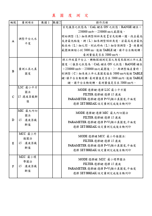
真圓度測定
二: 問題研討
1項目所使用的量測程序是否能量測出符合其定義之量測值?
2.使用真圓度機量測真圓度,與其他方法所得之量測值結果,有何不同?
3.請說明真圓度量測知意義級量測時需注意事項。
儀器:真圓度測定使用動力:空氣壓力
問題研討
1.LSC MIC MCC MZC 這四種真圓度量測法,實際上以何種方法
作為量測依據
2.真圓度使用的量測程序是否能量測出符合其定義之量測值
3.你使用真圓度機量測真圓度,與其他方法之量測結果有何不同
真圓度量測
二:問題研討
1:你認為你所測得的工件真圓度是否準確?為甚麼?
2:真圓度機器的應用性量測包含了平面度、同軸度、直角度、同心度及平行度等,請問你量測了哪些項目?
3:LSC、MIC、MCC、MZC這四種真圓度量測之方法,實際上是以哪種作為依據。
圆度、圆柱度测量仪ppt课件
二级 0.5
三级 0.8
四级 1.0
➢室内周围应无影响测量的灰尘、振动、噪音、较强的磁场 等
➢受检仪器在室内连续恒温时间应不小于24小时,标准器具 在室内恒温时间应不小于4小时
整理版课件
5
三、主要计量性能要求
整理版课件
6
整理版课件
7
四、仪器示值误差
测量 方法
圆度仪
超精密微动台法
椭圆标准器法
圆柱度仪 标准圆柱体
圆度、圆柱度测量仪
Measurement Standard Instrument of Roundness and
Cylindricity
整理版课件
1
一、概述
基准:
圆度仪
圆柱度仪
回转测量基准
直线测量基准
精密回转中心
精密直线运动导轨
整理版课件
2
一、概述
原理:
圆度仪:通过传感器测量被测件不同转角位置上的实际轮 廓到回转中心半径的变化量。
8
四、仪器重复性
测量方法
圆度仪
圆柱度仪
在椭圆标准器的同一截面上连 续测量5次,得到5个测量结果
用截面法在100mm高度内取至 少5个截面进行圆柱度测量,重
复5次
五、检定结果的处理
➢检定合格的圆度、圆柱度测量仪发给检定证书; ➢检定不合格的发给检定结果通知书,并注明不合格项 目
内容
用驱动器驱动工作台使传
感器在量程范围内等间距 移动10个位置
圆度标称值分别为 0.5μm,1μm,2μm,
4μm,5μm
用截面法在100mm高度 内取至少5个截面进行圆 柱度测量,重复5次,其
平均值作为测得值
圆度测量
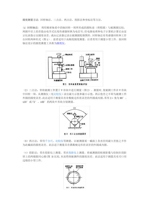
圆度测量方法: 回转轴法、三点法、两点法、投影法和坐标法等方法。
(1)回转轴法: 利用精密轴系中的轴回转一周所形成的圆轨迹(理想圆)与被测圆比较,两圆半径上的差值由电学式长度传感器转换为电信号,经电路处理和电子计算机计算后由显示仪表指示出圆度误差,或由记录器记录出被测圆轮廓图形。
回转轴法有传感器回转和工作台回转两种形式(图1)。
前者适用于高精度圆度测量,后者常用于测量小型工件。
按回转轴法设计的圆度测量工具称为圆度仪。
(2)三点法:常将被测工件置于V形块中进行测量(图2)。
测量时,使被测工件在V形块中回转一周,从测微仪(见比较仪)读出最大示值和最小示值,两示值差之半即为被测工件外圆的圆度误差。
此法适用于测量具有奇数棱边形状误差的外圆或内圆,常用2α角为90°、120°或72°、108°的两块V形块分别测量。
(3)两点法:常用千分尺、比较仪等测量,以被测圆某一截面上各直径间最大差值之半作为此截面的圆度误差。
此法适于测量具有偶数棱边形状误差的外圆或内圆。
(4)投影法:常在投影仪上测量,常在投影仪上测量,将被测圆的轮廓影像与绘制在投影屏上的两极限同心圆(图3)比较,从而得到被测件的圆度误差。
此法适用于测量具有刃口形边缘的小型工件。
(5)坐标法:一般在带有电子计算机的三坐标测量机上测量。
按预先选择的直角坐标系统测量出被测圆上若干点的坐标值x、y,通过电子计算机按所选择的圆度误差评定方法计算出被测圆的圆度误差。
圆度误差评定就是将双绞线导线横截面的实际轮廓与理想圆比较的过程。
圆度误差评定方法:①最小区域法:以包容被测圆轮廓的半径差为最小的两同心圆的半径差作为圆度误差。
②最小二乘圆法:以被测圆轮廓上相应各点至圆周距离的平方和为最小的圆的圆心为圆心,所作包容被测圆轮廓的两同心圆的半径差即为圆度误差。
③最小外接圆法:只适用于外圆。
以包容被测圆轮廓且半径为最小的外接圆圆心为圆心,所作包容被测圆轮廓的两同心圆半径差即为圆度误差。
《圆度误差的测量》课件
球面测量法
使用具有球面曲率的测量仪器 进行测量,适用于小批量生产。
运动轮廓法
通过测量运动轮廓的变化来推 断工件的圆度误差。
测量工具
星形指示仪
通过接触工件表面并检测变形 以测量圆度误差。
光学环形投影仪
利用光学原理进行投影和测量, 精度更高。
三点法测量仪
使用三个测量点来确定工备
确保测量仪器的准确性和稳定性,以及工件表面的清洁度。
2 测量步骤及方法
按照测量方法的步骤进行操作,注意测量点的选择和测量顺序。
3 实验注意事项
注意避免外界干扰因素对测量结果的影响,进行多次测量以提高准确性。
结论与应用
圆度误差的测量结果处理
根据测量结果进行数据分析和处理,以确定工件的圆度误差。
圆度误差的应用场景
圆度误差的准确测量对于精密零件制造、机械装配和精密仪器具有重要意义。
《圆度误差的测量》PPT 课件
本课程将介绍圆度误差的测量方法和工具使用,以及相关注意事项和应用场 景。
简介
圆度误差的概念
圆度误差是指实际圆形与理论圆形之间的偏差。
圆度误差的影响
圆度误差会影响零件的机械性能、运动平稳度 和密封性能。
测量方法
机床测量法
使用机床上的测量装置对工件 进行测量,适用于大批量生产。
真圆度仪培训内容
真圆度仪培训内容当时为了解决圆度测量滤波问题,希望通过培训来达到,为此联系福州力丰(曾向其购买测头),向其询问售后问题由谁负责,福州力丰告知东莞力丰,致电东莞力丰,东莞力丰只提供售后故障处理,并告知培训业务由上海力丰负责,因此与上海力丰联系培训事宜。
并告知圆度仪型号,由于双方均未考虑到软件问题,所用软件在台湾被翻译,许多功能未翻译不全,导致不可使用,但滤波设定范围只有15-500,没有更小值,英文版也是如此。
本次圆度仪的培训目的是为了解决滤波的处理问题,当时一、维护保养:1.气压:在0.4MPa以上2.排水排油:当发现油水过滤器有水或油时,应及时排掉。
若发现气管出现油水应更换过滤器滤芯。
二、调水平:更改LX、L Y值1.于量测菜单下点击“水平状态”,弹开窗口后选择如下:○多点●标准要素形式:●螺旋要素+半径量测方向:●上端、○下端2.于量测菜单下点击“水平调整”,注意测针不撞到量测倍率:从大往水调转盘从中心外圈75mm,半径输入点击“下一步”→“下一步”显示水平调整值LX、L Y,更改后并归零。
并重复以上步骤直至LX、L Y值为0。
然后点击“停止水平调整”。
三、调中心:更改CX、CY值1.于量测菜单下点击“中心状态”,弹开窗口后选择如下:○多点●标准量测方向:●外侧、○内侧2.于量测菜单下点击“中心调整”,点击“下一步”→“下一步”显示中心调整值CX、CY,更改后并归零。
并重复以上步骤直至CX、CY值为0。
然后点击“停止中心调整”。
四、校正:更换测针时均要进行测针校正:1.水平调整:专用橡胶片(无),以两块相差约22um的块规紧压在平晶上替代。
2.校正状态:标准:块规断差,X轴移到近似零位确定:测针放到高的块规,点击“下一步”,显示X值,再移到另一块,点击“下一步”,3.静态校正“下一步”,显示X=0.00,手动移到另一块量块,“下一步”登记校正值:量测资讯,名称:可输入→登记→确定。
五、呼叫校正值:可调出历史校正资料六、整机校正:要求0.07+6H/10000um,即0.086um,滤波选择2CR PL75%,扣除标准求误差,即测得值-标差。
真圆度

Precision Metrology Lab.
真圓度量測儀的構造
Precision Metrology Lab.
真圓度量測儀的種類
• 旋轉收錄器 • 旋轉工作臺
Precision Metrology Lab.
Precision Metrology Lab.
旋轉工作臺式 二
Precision Metrology Lab.
真圓度量測儀的主要組成
• 工作台(Worktable)
可做逕向移動及傾斜角度等調整,依廠牌而不同。
• 收錄器(Pick-up)
使用線性差動變壓器(LVDT) ,探針使用硬鋼而針尖使 用寶石製成
旋轉收錄器式
• Rotating Pick-up type • 工件固定,主軸及量錶繞 工件旋轉 • 精密的儀器主軸只承受一 定轉速即固定負荷的收錄 器,可達高精度 • 工作台不屬於量測系統, 故工件重量不受限制
Precision Metrology Lab.
旋轉工作臺式 一
• • • • Rotating Table type 工件旋轉,量錶固定 使用兩支收錄器可縮短量測時間 收錄器和主軸不相關,容易量測其他性質,如: 同心度、平行度等 • 有更多方式決定收錄器位置,不需用長型或曲 型的探針臂 • 旋轉工作台及工件重量由轉軸支持,受限制 • 轉軸與工件軸心不同時需調整,否則易有誤差
三點探針法
• 為具有120° 間隔的三點探針 • 常用於量測不規則形狀
Precision Metrology Lab.
準確主軸(量測主軸)法
• 使用準確主軸法,才是量測真圓度的唯一準確 方法 • 分 a. 旋轉收錄器式 b. 旋轉工作臺式
工程测量(2)圆曲线测量指导书5
工程测量实验教学指导书(圆曲线放样)课程名称:工程测量学(2)课程编码:66121548学时数;4学时开课单位:资建学院适用专业:测绘BG1、实验课的性质与任务本课程是测绘工程、工程测量的专业课。
本课程的任务是通过教学使学生获得工程测量方面的基本知识、基本理论和基本技能,培养学生分析问题和解决问题的能力,为以后走向工作岗位从事测绘工程奠定重要基础。
2、实验目的与要求2.1工程放样目的;通过放样掌握放样数据计算,放样方法选择,放样精度分析预计以及放样工作设计。
2.2放样数据计算。
要求计算准确,并进行精度预计,写出设计内容。
2.3实地放样。
要求操做认真,培养学生动手能力和分析问题,解决问题能力。
2.4在JD点立仪器,放出T距离,定点ZY。
在曲线起点放样出各点,一直到QZ点重合,并量出闭合差。
2.5每20米一点放样。
3、实验项目及内容提要在实训基地进行。
采用极坐标法放养点位,在两个实训基地进行。
坐标值如下;实验课;曲线放样各组根据自己的选好的已知点可以在操场上放样标出。
放样圆曲线,65人分为12个组,指导教师;顾德元周洪华赵琴霞4、实验报告的格式按学校统一格式5、本课程考核方式、方法及实验成绩评定方法考核方式采取现场考核检查与编写报告相结合方式。
各占50%。
成绩为;优,良,中,及格,不及格:不及格者不允许参加期末考试。
6、实验应配套的主要仪器设备及台(套)数(以一个实验教学班为标准)经纬仪一台,花杆两只,测钎10个,皮尺一个。
以上为每5人一组确定。
7、大纲有关说明实验报告要根据内容调整,不统一。
一个项目一样。
大纲撰写人:顾德元大纲审阅人:负责人:2012年 08月27日。
圆度,圆柱度及球度的测量及评价方法讲解
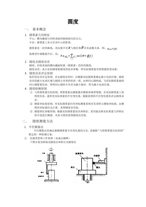
圆度一. 基本概念1. 圆要素几何特征中心:横向截面与回转表面的轴线相交的交点; 半径:圆要素上各点至该中心的距离。
圆要素是一封闭曲线,其向量半径R 与相位角θ具有函数关系,即:()R F θ=按傅里叶级数展开后,有:()001cos mk k R k k a c θθ==++∑2. 圆度及圆度误差圆度:回转表面的横向截面轮廓(圆要素)的形状精度;圆度误差:表示实际圆要素精度的技术参数,即实际圆要素对理想圆的变动量。
3. 圆度误差评定原则按形状误差评定原则,评定圆度误差时,应根据实际圆要素确定最小包容区域。
圆度误差的最小包容区域与圆度公差带的形状一致,由两同心圆构成,当实际圆要素被两同心圆紧紧包容,即两同心圆的半径差为最小值时,即为最小包容区域。
4. 圆度检测原则① 与理想要素比较原则:理想要素由测量器具模拟体现理想圆。
在实际圆要素上获得的信息,通常是实际要素的半径变化量,根据获得的半径变化量再评定圆度误差。
② 测量坐标值原则:对实际圆要素应用坐标测量系统对其采样点测取坐标值,由测得的坐标值经过计算,求得圆度误差值。
③ 测量特征参数原则:根据实际圆要素的具体特征,采用能反映实际要素几何特征的手段进行测量,从而方便的获得圆度误差值。
二. 圆度测量方法1. 半径测量法半径测量法是确定被测圆要素半径变化量的方法,是根据“与理想要素比较原则”拟定的一种检测方案。
① 仪器类型和工作原理(加备注解释)下图分别为转轴式圆度仪和转台式圆度仪圆度仪可运用测得信号的输出特性,将被测轮廓的半径变化量放大后同步自动记录下来,获得轮廓误差的放大图形,可按放大图形评定圆度误差。
② 用圆度仪测量注意事项(加备注择项解释)选择适当的侧头类型;静态测量力选择;测量平面和测量方向确定;频率响应选择;选择适当的放大倍率;正确安装被测件,径向偏心和轴向倾斜;主轴误差的影响2. 坐标测量法坐标测量法是根据测量坐标值原则提出的一种检测方案。
数学人教版六年级下册圆的认识与测量

圆的认识教学设计授课教师:陈蕊教学内容人教版六年级下册第五单元教材P57——P58。
教学目标1、使学生认识圆,知道圆的各部分名称。
2、使学生掌握圆的特征,理解和掌握在同一个圆里半径和直径的关系。
3、初步学会用圆规画圆,培养学生的作图能力。
4、培养学生观察、分析、抽象、概括等思维能力和动手操作能力。
教学重点圆的认识,通过动手操作,理解直径与半径的关系,认识圆的特征。
教学难点画圆的方法,认识圆的特征。
教学用具课件、大小不同的圆、圆规教学课时一课时教学过程一、师生谈话,导入新课师:同学们这节课老师给大家带来一些美丽的图案,你们想看吗?生:想看。
师:看时请同学们认真观察这些图案有什么共同特征?生:这些图案都是由圆形组成的。
师:对!这么美的图案你们能画出来吗?(不能)这节课我们就一起研究有关圆的知识,相信大家不但学会圆的许多知识,还能画出比老师还要美的图案。
二、自主学习,合作探究。
1、课件出示圆的图片提问:这是什么图形?在我们的生活周围你还知道哪些物体的形状是圆形的?2、圆是用什么线围成的?学生举例说。
(硬币、茶杯盖的形状、玻璃器皿的外形等等)那么,什么叫圆呢?它与我们以前学过的平面图形有什么不同?学生回答后,教师进行小结:圆是平面上的一种曲线图形。
3、动手操作,研究特征。
通过具体操作,来认识一下圆的各部分名称和圆的特征。
(1)先把圆对折、打开,换个方向,再对折,再打开……这样反复折几次。
教师提问:折过若干次后,你发现了什么?(在圆内出现了许多折痕)仔细观察一下,这些折痕总在圆的什么地方相交?(圆的中心一点)教师指出:我们把圆中心的这一点叫做圆心。
圆心一般用字母O表示。
教师板书:圆心(2)用尺子量一量圆心到圆上任意一点的距离,看一看,可以发现什么?(圆心到圆上任意一点的距离都相等)我们把连接圆心和圆上任意一点的线段叫做半径,半径一般用字母r 表示。
(教师在圆内画出一条半径,并板书:半径)(3)同学继续观察:刚才把圆对折时,每条折痕都从圆的什么地方通过?两端都在圆的什么地方?我们把通过圆心并且两端都在圆上的线段叫做直径。
工程制图之圆的正等测图教学课件
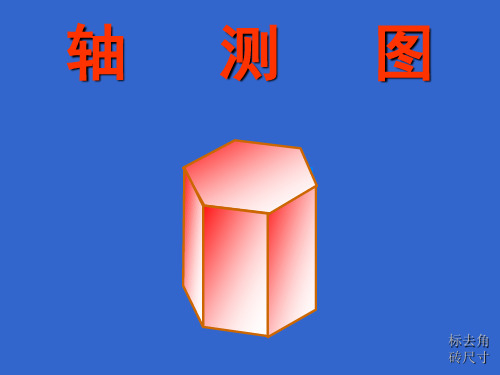
标去角 砖尺寸
➢曲面体
圆的轴测图为椭圆,椭圆的画法:
1、坐标法:一般找八(四)点并光滑连接, 适用于包括平面体在内的任何情况。
2、四心法:由四段圆弧近似组成椭圆,只适 用正等测且圆平行于投影面的情况。
平行于各坐标面的圆的正等测投影图均为 椭圆, 但长、短轴的方向不同。
Z
O
X
Y
练习找四点画椭圆
4
2、四心法
1
2xo源自O24 2y3
O3
O4
x1
3y
O1
练习四心法
回转体的正等测画法:画出回转体上平行于坐
标面的圆的轴测椭圆,然后作椭圆的切线。
o o
h
h
h
圆锥
学生练习:圆台(坐标法找四点)
真圆度之定义与量测 (1)
真圓度之定義與量測
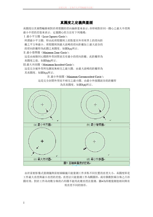
真圓度以其實際輪廓相對於理想圓的徑向偏移量來表示,亦即相對於同一圓心之最大半徑與最小半徑的差值來表示。
定義圓心的方法有下列幾種:
Ⅰ.最小平方圓(Least Squares Circle):
所謂最小平方圓,即由此理想圓周上的點量至外形周界上的徑向距
離之平方和最小。
理想圓周到最大波峰的徑向距離加上最大波谷的
的徑向距離即為此圓之真圓度。
如圖3(a)所示。
Ⅱ.最小環帶圓(Minimum Zone Circle):
這是由兩個同心圓將外型封閉並且有最小的徑向距離,此距離即為
真圓度之值。
如圖3(b)所示。
Ⅲ.最大內切圓(Maximum Inscribed Circle):
這是完全被外型所包圍而無相交之最大圓。
由最大波峰的距離即為
其真圓度。
如圖3(c)所示。
Ⅳ.最小外接圓(Minimum Circumscribed Circle):
這是完全封閉外型而不相交之最小圓。
由最小外接圓波谷的距離即
為其真圓度。
如圖3(d)所示。
由於雷射影像式量測儀與雷射掃瞄儀只能量測工件多點不同位置的直徑大小,真圓度即是工件最大直徑與最小直徑的差值,直徑法只能量測工件為橢圓形,或有偶數對稱分佈之凸形圓有效,對於工件為奇數分佈的凸形圓不能用此種直徑法量測。
圖4為四種量測值相同與有
效直徑不同的情形。
圖4 四種量測值相同與有效直徑不同的情形。
真圆度测定
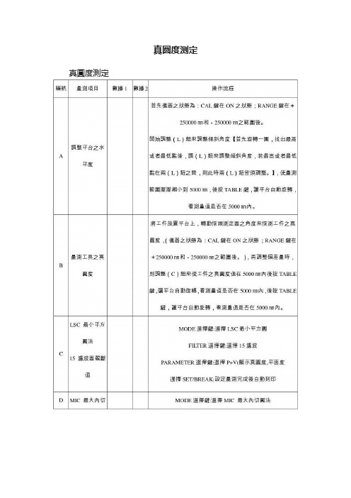
真圆度测定真圓度測定
二: 問題研討
1項目所使用的量測程序是否能量測出符合其定義之量測值?
2.使用真圓度機量測真圓度,與其他方法所得之量測值結果,有何不同?
3.請說明真圓度量測知意義級量測時需注意事項。
儀器:真圓度測定使用動力:空氣壓力
問題研討
1.LSC MIC MCC MZC 這四種真圓度量測法,實際上以何種方法作為量測依據
2.真圓度使用的量測程序是否能量測出符合其定義之量測值
3.你使用真圓度機量測真圓度,與其他方法之量測結果有何不同
真圓度量測二:問題研討
1:你認為你所測得的工件真圓度是否準確?為甚麼?
2:真圓度機器的應用性量測包含了平面度、同軸度、直角度、同心度及平行度等,請問你量測了哪些項目?
3:LSC、MIC、MCC、MZC這四種真圓度量測之方法,實際上是以哪種作為依據。
圆度的测量方法
圆度的测量方法圆度是衡量圆形几何性质的重要指标之一,指圆的外形是否对称、完美。
在实际应用中,为了确保产品的质量,需要对圆的圆度进行测量。
本文将介绍圆度的测量方法。
一、工具准备圆度测量需要使用精密量具,下面是其中两种:1.万能三角板:通常用于平面内角度测量,可以通过计算圆的内角得出圆度。
2.圆度指示仪:圆度指示仪用于测量零件的圆度误差、偏心度等参数。
二、圆度测量方法1.使用万能三角板圆度测量方法:(1)将三角板中间的刻度盘装置嵌入由旋转的小圆心支撑的待测零件内。
(2)让该圆料以很小的转速旋转。
(3)读取三角板上的内角数据,并根据内角计算出圆度值。
计算方法为可以通过圆度公式进行计算,公式如下:圆度= (180°/π - θ)× (d/2)。
2.使用圆度指示仪圆度测量方法:(1)将圆度指示仪的圆柱形探头移至待测零件的中心位置。
(2)打开圆度指示仪的电源,开始测量。
(3)通过观察圆度指示仪的指针指向刻度,测量被测零件的圆度值。
三、测量注意事项1.测量时需要注意测量环境的温度湿度和震动情况,以保证测量结果的准确性。
2.测量前需认真清洁测量工具和被测零件,以防止灰尘等杂质影响测量结果。
3.不同的测量方法适用于不同类型的零件,需要根据实际情况选择最适合的测量方法。
4.测量后要及时清理和保养测量工具,避免影响下次的测量。
综上所述,圆度是衡量圆形几何性质稳定性的重要参数之一。
通过万能三角板和圆度指示仪等工具的使用可以准确测量圆度,提高产品的质量。
同时,在测量过程中需要注意各种细节,确保测量结果的准确性。
真圆度测量方法
真圆度测量方法真圆度是指物体表面的轮廓与理想圆的偏差程度,是衡量物体圆形度的重要指标。
在工程领域中,真圆度的测量对于保证零件的精度和质量至关重要。
因此,掌握真圆度的测量方法对于工程技术人员来说是非常重要的。
本文将介绍几种常用的真圆度测量方法,以供参考。
首先,最常见的真圆度测量方法是使用测微计。
测微计是一种精密测量仪器,可以用来测量物体表面的高度差。
在测量真圆度时,可以将测微计沿着物体的周边轻轻滑动,记录下不同位置的高度值,然后通过计算得出真圆度的偏差值。
测微计测量的优点是精度高,结果可靠,适用于对真圆度要求较高的场合。
其次,光学投影仪也是一种常用的真圆度测量方法。
光学投影仪可以将物体的轮廓投影到屏幕上,通过对投影图像的测量来得出真圆度的偏差值。
使用光学投影仪测量真圆度的优点是快速、直观,适用于对真圆度要求较低的场合。
另外,三坐标测量机也可以用来测量真圆度。
三坐标测量机是一种精密测量设备,可以通过探针对物体表面进行三维坐标的测量。
在测量真圆度时,可以通过三坐标测量机得到物体表面各点的坐标值,然后通过计算得出真圆度的偏差值。
三坐标测量机测量的优点是精度高,适用于对真圆度要求非常高的场合。
最后,还有一种常用的真圆度测量方法是使用投影仪。
投影仪可以将物体的轮廓投影到屏幕上,通过对投影图像的测量来得出真圆度的偏差值。
使用投影仪测量真圆度的优点是简单、快速,适用于对真圆度要求较低的场合。
总之,真圆度的测量方法有很多种,每种方法都有其适用的场合和特点。
工程技术人员在选择真圆度测量方法时,需要根据具体的要求和条件来进行选择,以保证测量结果的准确性和可靠性。
希望本文介绍的真圆度测量方法能够对工程技术人员有所帮助。
真圆度测量方法

真圆度测量方法
真圆度测量是一种精密测量,主要用于确定零件表面是否符合真圆度要求。
传
统的真圆度测试技术是以坐标测量机和单点测量技术为主要工具,但由于传统测试技术设备昂贵、操作繁琐,定位不精确,测量结果可信度下降,使得真圆度测量技术受到限制。
随着国家对汽车、航空航天等一系列高要求的产品的需求不断增加,真圆度测
量技术也受到了极大的关注。
为了满足生产需求,相应的先进设备和技术也在各大公司中被广泛使用,比如三维扫描测量系统,这种系统拥有一套完善的先进算法,可以准确定义零时低量元圆度等精密数据,并将其显示出来,使操作的可视性更强,测量的准确性也更好,大大提高了测量效率和可信度。
此外,经过坐标测量机,管束视觉等多种测量技术的发展,传统的真圆度测试
也从“三维档案”发展为“二维扫描”,大大提高了测量的准确性。
同时,互联网技术的发展使得真圆度测量技术变得越来越丰富,采用在线云端计算等技术,可以实现实时数据监控和测试诊断,令整个真圆度测量技术变得更加完善。
因此,真圆度测量技术日趋完善和成熟,对获得准确测量结果有莫大的帮助。
未来,随着科学技术的发展,真圆度测量技术发展势头不减,三次元立体断层测量技术、X射线技术等新技术将会得到更加广泛地应用,为改善测量准确性、提高可
信性和减少测量成本提供重要的参考。
圆度 圆柱度测量 ROUNDTEST RA-2200系列 形状测量说明书
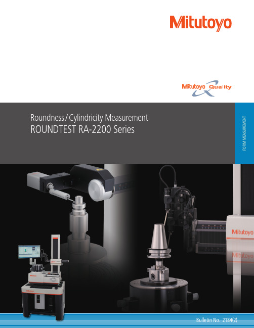
R A-2200AS/AH models are supplied as standard with an automatic centering and leveling turntable, freeing the operator from the centering and leveling task.RA-2200DS/DH models are supplied as standard with a navigation function that quickly and simply guides the operator through the centering and leveling task, as though the task were being performed by an expert.All models are equipped with a highly accurate turntable that enables simple and accurate centering and leveling of the workpiece, which account for the majority of the essential setup work for measuring roundness/cylindricity.The table provides high rotational accuracy (radial 0.02+3.5H/10000 μm; axial 0.02+3.5X/10000 μm), enabling the system to measure flatness and other characteristics, in addition to roundness/cylindricity, at a level that suits any application.For centering and leveling support, you can select either the A.A.T. (Automatic Adjustment Table) or D.A.T. (Digimatic Adjustment Table).Centering and leveling using an A.A.T. or D.A.T.* can be integrated in the measurement procedure (part program). This can prevent mistakes such as forgetting to center and level during measurement and is intended to standardize measuring work through part-program measurement.*Models equipped with a D.A.T. require manual adjustment of centering and leveling misalignments.Equipped with a highly accurate turntable that enables simple and accurate centering and leveling of the workpieceThe photo showsRA-2200 + vibration isolator with monitor arm.The photo showsRA-2200 +vibration isolator with side table.Display of misalignmentsROUNDTEST RA-22003211), 2) : External diameter measurement 3) : Internal diameter measurement : Displacement3) = inner diameter: Up to ø50 mmThe spiral-mode measurement function combines table rotation and rectilinear action allowing cylindricity, coaxiality, and other data to be loaded as a continuous data set.Spiral Measurement/AnalysisRetrofit kits are available for the RA-2200AS and RA-2200AH to add the automatic measurement functionality found in their PLUS counterparts.*See page 4 for details.Retrofit kits can be used with models equipped with motorized detector-unit holdersMeasurement while tracing is possible through a built-in linear scale in the X-axis. This type of measurement is useful when displacement due to form variation exceeds the measuring range of the sensor, and X-axis motion i s n e c e s s a r y t o maintain contact with the workpiece surface.Measurement through X-axis tracking Even if a workpiece cannot be measured by physically rotating it by a full turn due to some obstruction (projection), segments of the circumference can be measured.Partial circle measurement function A safety mechanism is incorporated into the detector unit area. A collision-sensing function has been added to the detector unit (when it is in the vertical orientation) to prevent collision in the Z-axis direction. Additionally, an accidental collision prevention function, which stops the system when the detector unit displacement exceeds its range, has been added. When an accidental touch is detected, the dedicated analysis software (ROUNDPAK) senses the error and automatically stops the system.Safety mechanism provided as a standard feature Highly accurate repeat measurements Continuous internal/external diameter measurement is possible without changing the detector position.Continuous OD/ID measurement function The detector-unit holder is equipped with a sliding mechanism, enabling one-touch measurement of a workpiece with a deep hole having a thick wall, which has been difficult with the conventional standard arm.Sliding detector-unit holder provided as a standard feature The detector-unit holder can be stopped at a position sufficiently higher than the workpiece along the Z-axis, and then lowered and positioned to make measurements.Furthermore, internal/external diameters can be easily measured with the continuous internal/external diameter measurement function.High accuracy even at high positioning speeds Continual development has resulted in the highest drive speed within the class.• Vertical direction (Z-axis column): Max. 50 mm/s • Radial direction: Max. 30 mm/sMitutoyo’s linear scales are incorporated into the X-axis positioning sensor, directly sensing the displacement of the drive unit to achieve highly accurate positioning, which is essential for repeat measurements.When an optional roughness detector unit is incorporated into the system it can measure workpiece surface roughness in the circumferential direction around the θ-axis, as well as roughness in the direct-drive directions along the X- and Z-axes with the table stopped.Roughness detector unit supportThis function controls the orientation of the arm holding the detector unit (between vertical and horizontal) and the detector unit rotation mechanism (between 0 and 270 degrees in 1-degree increments), making it possible to continuously and automatically measure internal/external diameters as well as top/bottom surfaces. Additionally, a full-featured offline teaching function simplifies the creation of part programs.Detector unit orientation programmable for CNC measurementROUNDTEST RA-2200 PLUSThe photo showsRA-2200 PLUS + vibration isolator with side table.The photo showsRA-2200 PLUS+ vibration isolator with monitor arm.**Printer table is a special Accessory.The system comes standard with the A.A.T. (Automatic Adjustment Table) positioning and leveling function, freeing the operator from the task of centering and leveling the workpiece.Simple and accurate centering and leveling of the workpiece Even if a workpiece cannot be measured by physically rotating it by a full turn due to some obstruction (projection), segments of the circumference can be measured.High accuracy even at high positioning speeds Partial circle measurement function Continual development has resulted in the highest drive speed withinthe class.• Vertical direction (Z-axis column): Max. 50 mm/s • Radial direction: Max. 30 mm/sA Mitutoyo linear scale is incorporated into the X-axis positioning sensor, directly sensing the displacement of the drive unit to achieve highly accurate positioning, which is essential for repeat measurements. Furthermore, continual development has resulted in the highest drive speed within the class while achieving high accuracy even at high positioning speeds.Highly accurate positioning sensorThe table provides high rotational accuracy (radial 0.02+3.5 H/10000 μm; axial 0.02+3.5X/10000 μm), enabling the system to measure flatness and other characteristics, in addition to roundness/cylindricity, at a level that suits any application.Highly accurate turntable When an optional roughness detector unit is incorporated into the system it can measure workpiece surface roughness in the circumferential direction around the -axis, as well as roughness in the direct-drive directions along the X- and Z-axes with the table stopped.Roughness detector unit support This highly adjustable detector unit is for installation on motorized detector-unit holders.Features of this detector unit include the ability to use alternative styli for the RA-2200* and freely change the angle of the stylus.*See page 7 for alternative styli.Detector unit II (option)Measurement while tracing is possible through a built-in linear scale in the X-axis. This type of measurement is useful when displacement due to form variation exceeds the measuring range of the sensor, and X-axis motion is necessary to maintain contact with the workpiece surface.Measurement through X-axis tracking Continuous internal/external diametermeasurement is possible without changing the detector position.Continuous OD/ID measurement functionHighly accurate repeat measurements Mitutoyo’s linear scales are incorporated into the X-axis positioning sensor, directly sensing the displacement of the drive unit to achieve highly accurate positioning, which is essential for repeat measurements.The spiral-mode measurement function combines table rotation and rectilinear action allowing cylindricity, coaxiality, and other data to be loaded as a continuous data set.Spiral Measurement/Analysis 3211), 2) : External diameter measurement 3) : Internal diameter measurement : Displacement3) = inner diameter: Up to ø50 mmA wide variety of parameters including those for roundness/cylindricity, as well as flatness and parallelism, are provided as standard features. You can visually select these parameters using icons.ROUNDPAK also comes with specialized functions, such as the design value best-fit analysis function, the harmonic analysis function, and a function for recording the peak or trough points on a circumference. Data that has already been collected can be easily used for re-calculation, or deleted.Roundness/Cylindricity measurement/Analysis softwareROUNDPAKROUNDPAK provides simple manipulation using a mouse and iconsSimple operations even with a full set of parameters and analysis functionsFreedom in laying out the graphics and data obtained from measurementsThe customer can create reports in custom formats by specifying how the analysis results will be displayed, as well as the sizes and positions of graphics. The analysis result window can be directly utilized as a layout window. Since the measurement procedure, including the layout information, is saved, the entire process, from measurement start, calculation, result saving, and finally to printing, can be automatically executed.RecalculationData deletionPatent registered in Japan, USA Patent pending in EuropeAn offline teaching function is provided to create a part program (measurement p r o c e d u r e) w i t h o u t a n a c t u a l measurement target, enabling the user to virtually execute the measurement operation in a 3D simulation window. You can also display warnings * about the risk of collision on the simulation window.* T his function is for R A-2200 PLUS only.Off-line measurement procedure programming functionQuick Launcher is provided as a standard feature. This enables simple and intuitive operation, so part programs can be run easily. Part programs can also be run by scanning barcodes or QR codes.MitutoyoLauncher support Analysis results such as cylindricity and coaxiality can be visuallyexpressed in 3D graphics.A wide variety of graphics functions Normal display Wire-frame display Surface-map display Shading displayRemote machine monitoringStatusMonitor Analysis of bearing sliding surfaces is provided as a standard feature.Harmonic tolerance verification / Velocity analysis*2: Customized special interchangeable styli are available on request. Please contact any Mitutoyo office for more information.Styli for RA-2200 (Option)Optional AccessoriesUnit: mmM agnificationcalibration gage211-045Used for normalizing detectormagnification by calibrating detector travel againstdisplacement of a micrometer spindle.•Maximum calibration range:400 μm•Graduation: 0.2 μm•External dimensions (WxDxH):235 (max) x 185 x 70 mm •Mass: 4 kgCylindrical square350850•Straightness: 1 μm •Cylindricity: 2 μm•External dimensions (DxH):ø70 x 250 mm•Mass: 7.5 kgStyli for RA-2200 PLUSOptions common to the RA-2200 and RA-2200 PLUSC entering chuck(ring operated)211-032Suitable for holding small parts with easy-to-operate knurled-ring clamping.•Holding capacity:Internal jaws: OD = ø1 - ø36 mm, ID = ø16 - ø69 mm External jaws: OD = ø25 - ø79 mm •External dimensions (DxH):ø118 x 41 mm•Mass: 1.2 kgC entering chuck(key operated)211-014Suitable for holding longer parts and those requiring a relatively powerful clamp.•Holding capacity:Internal jaws: OD = ø2 - ø35 mm, ID = ø25 - ø68 mm External jaws: OD = ø35 - ø78 mm •External dimensions (DxH):ø157 x 70.6 mm•Mass: 3.8 kgMicro-chuck211-031Used for clamping a workpiece (less than ø1 mm dia.) that the centering chuck cannot handle.•Holding capacity: ø0.2 - ø1.5 mm •External dimensions (DxH):ø107 x 48.5 mm•Mass: 0.6 kg•Vibration isolator178-025 / 178-188•Monitor arm12AAK120•Side table178-181•Surface RoughnessDetector Holder for non-CNC12AAY644•RA-2200AS/AH,retrofit to RA-2200A PLUS12AAX863Unit: mm 25.4mm=1”SpecificationsUnit: mm25.4mm=1”DimensionsDimensionsRA-2200RA-2200 PLUSwith vibration isolator and side tablewith monitor arm ** Printer table is a special accessory.Unit: mm 25.4mm=1”Sensor SystemsTest EquipmentDigital Scale and DRO SystemsSmall Tool Instruments and Data Managementbasis.Mitutoyo America Corporation One Number to Serve You Better 1-888-MITUTOYO (1-888-648-8869)M 3Solution Centers:Aurora, Illinois (Headquarters)Boston, Massachusetts Charlotte, North Carolina Cincinnati, Ohio Detroit, Michigan Los Angeles, California Seattle, Washington Houston, Texas© 2023 M i t u t o y o A m e r i c a C o r p o r a t i o nFind additional product literature and our product catalogNote: All inform ation regarding our products, and in particular the illustrations, drawings, dim ensional and perform ance data contained in this printed matter as well as other technical data are to be regarded as approximate average values. We therefore reserve the right to make changes to the corresponding designs. The stated standards, similar technical regulations, descriptions and illustrations of the products were valid at the time of printing. In addition, the latest applicable version of our General Trading Conditions will apply. Only quotations submitted by ourselves may be regarded as definitive. Specifications are subject to change without notice.Mitutoyo products are subject to US Export Administration Regulations (EAR). Re-export or relocation of our products may require prior approval by an appropriate governing authority.Trademarks and RegistrationsDesignations used by companies to distinguish their products are often claimed as trademarks. In all instances where Mitutoyo Am erica Corporation is aware of a claim, the product nam es appear in initial capital or all capital letters. The appropriate companies should be contacted for more complete trademark and registration information.0423 • FOR WEB ONLY • April 2023Mitutoyo End User Portalputs everything Mitutoyo Search for products, request a product quote, take online metrology courses, and much more. directly in front of you.。
- 1、下载文档前请自行甄别文档内容的完整性,平台不提供额外的编辑、内容补充、找答案等附加服务。
- 2、"仅部分预览"的文档,不可在线预览部分如存在完整性等问题,可反馈申请退款(可完整预览的文档不适用该条件!)。
- 3、如文档侵犯您的权益,请联系客服反馈,我们会尽快为您处理(人工客服工作时间:9:00-18:30)。
精密量測
真圓度量測
真圓度定義
圓形工件偏移幾何圓程度大小 實際輪廓相對於理想圓徑向偏移量
真圓度表示方法
最小平方圓法(LSC) 最小環帶圓法(MZC) 最大內切圓法(MIC) 最小外接圓法(MCC)
精密量測
真圓度量測
軸及軸承
精密量測
真圓度量測
真圓度誤差原因
精密量測
真圓度量測
真圓度表示方法(最小平方圓法)
精密量測
真圓度量測
真圓度量測儀操作(水平調整)
精密量測
真圓度量測
真圓度量測儀操作(中心調整)
精密量測
真圓度量測
真圓度量測儀放大顯示器
精密量測
真圓度量測
真圓度量測儀各部名稱
精密量測
真圓度量測
真圓度量測儀用途
平面度(―) 同心度(◎) 同軸度(○) 垂直度(⊥) 平行度(//)
真圓度量測儀比較
真圓度量測
真圓度量測法(直徑法)
精密量測
真圓度量測
真圓度量測法(周緣限制量規法)
精密量測
真圓度量測
真圓度量測法(兩頂心間)
精密量測
真圓度量測
真圓度量測法(V形枕量測法)
精密量測
真圓度量測
真圓度量測法(V形枕量測原理)
精密量測
真圓度量測
真圓度量測儀構造
轉軸 測頭
收錄器 探針
放大器 濾波器 記錄器 校正標準半圓球
最大圓
輪廓曲線 真圓度值 最小圓
精密量測
真圓度量測
真圓度表示方法
精密量測
真圓度量測
真圓度表示方法
精密量測
真圓度量測
真圓與偏差圓
精密量測
真圓度量測
真圓度量測方法
直徑法 V型枕量測法 兩頂心間旋轉法 周緣限制量規法 真圓度量測儀 轉軸式 轉盤式
測砧
精密量測
真圓度量測
真圓度量測法(直徑法)
精密量測
精密量測
真圓度量測 (Roundness Testing)
真圓度偏差原因 真圓度定義 真圓度表示方法 真圓度量測方法 真圓度量測儀構造 使用方法 用途
精密量測
真圓度量測
圓形形狀精度影響
振動、噪音、磨耗 其他品質
軸承
真圓度偏差原因
機器主軸抗磨性 夾持工件撓曲變形 抽(擠)製模具形狀 刀具缺陷
主軸 油膜
轉軸式 轉盤式
精密量測
真圓度量測
真圓度量測儀用途 (真圓度) (同心度) (圓偏轉度)
精密量測
真圓度量測
真圓度量測儀用途(真直度)(真平度)
精密量測
真圓度量測
真圓度量測儀用途(平行度)(垂直度)
精密量測
真圓度量測
真圓度量測儀量測方式(真圓度)
精密量測
真圓度量測
真圓度量測儀量測方式(平面度)
精密量測
真圓度量測
真圓度量測儀量測方式(圓柱體偏心度)
精密量測
真圓度量測
真圓度量測儀量測方式(垂直度)
精密量測
真圓度量測
真圓度量測儀量測方式(平行度)
精密量測
真圓度量測
真圓度量測誤差分析 儀器轉軸誤差 量測角度誤差 轉盤軸心與工件中心軸線不重疊 探針針尖形狀誤差 量測人員取值誤差
精密量測
真圓度量測
真圓度量測誤差(量測角度)
精密量測
真圓度量測
真圓度量測誤差(探針量測角度)
精密量測
真圓度量測
真圓度量測誤差(轉軸誤差)
精密量測
真圓度量測
真圓度量測誤差(軸線不對準)
精密量測
真圓度量測
真圓度量測誤差(探針針尖形狀)
精密量測
真圓度量測
真圓度量測儀系統
精密量測
真圓度量測
真圓度量測儀原理
精密量測
真圓度量測
真圓度量測儀原理
精密量測
真圓度量測
真圓度量測儀附件
精密量測
真圓度真圓度量測
真圓度量測儀電子放大系統
精密量測
真圓度量測
真圓度量測儀量測方式
精密量測
真圓度量測
濾波後真圓度圖形
