BL-YX18智能压力控制器标准型说明书
Omega PSW18H Series 液压, 杆式压力开关用户指南说明书
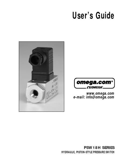
User’s Guide e-mail:**************PSW18H SERIES HYDRAULIC, PISTON-STYLE PRESSURE SWITCHOMEGAnet®On-Line Service Internet e-mail**************Servicing North America:USA:One Omega Drive, P.O. Box 4047ISO 9001 Certified Stamford, CT 06907-0047TEL: (203) 359-1660FAX: (203) 359-7700e-mail:**************Canada:976 BergarLaval (Quebec) H7L5A1TEL: (514) 856-6928FAX: (514) 856-6886e-mail:*************For immediate technical or application assistance:USA and Canada:Sales Service: 1-800-826-6342 / 1-800-TC-OMEGA®Customer Service: 1-800-622-2378 / 1-800-622-BEST®Engineering Service: 1-800-872-9436 / 1-800-USA-WHEN®TELEX: 996404 EASYLINK: 62968934 CABLE: OMEGAMexico:(001) 800-826-6342FAX: (001) 203-359-7807En Espanol: (001) 203-359-7803e-mail:*******************************.mxServicing Europe:Benelux:Postbus 8034, 1180 LA Amstelveen, The NetherlandsTEL: +31 (0)20 6418405FAX: +31 (0)20 6434643Toll Free in Benelux: 0800 0993344e-mail:************Czech Republic:Rudé armády 1868, 733 01 KarvináTEL: +420 (0)69 6311899FAX: +420 (0)69 6311114Toll Free in Czech Rep.: 0800-1-66342e-mail:***************France:9, rue Denis Papin, 78190 TrappesTel: +33 (0)130 621 400FAX: +33 (0)130 699 120Toll Free in France: 0800-4-06342e-mail:****************Germany/Austria:Daimlerstrasse 26, D-75392 Deckenpfronn, GermanyTel: +49 (0)7056 3017FAX: +49 (0)7056 8540Toll Free in Germany: 0800-TC-OMEGAe-mail:*****************United Kingdom:One Omega Drive, River Bend Technology CentreISO 9002 Certified Northbank, Irlam, ManchesterM44 5EX, United KingdomTel: +44 (0)161 777 6611FAX: +44 (0)161 777 6622Toll Free in the United Kingdom: 0800 488 488e-mail:*************.ukIt is the policy of OMEGA to comply with all worldwide safety and EMC/EMI regulations that apply. OMEGA is constantly pursuing certification of its products to the European New Approach Directives. OMEGA will add the CE mark to every appropriate device upon certification.The information contained in this document is believed to be correct, but OMEGA Engineering, Inc. accepts no liability for any errors it contains, and reserves the right to alter specifications without notice.WARNING: These products are not designed for use in, and should not be used for, patient-connected applications.Numbers in parentheses indicate measurement in bar.*Note: Hysteresis is not adjustable. Maximum values are shown.MATERIALS OF CONSTRUCTION Housing Aluminum / Steel Seal Dynamic PTFE Static Buna-N SPECIFICATIONSPorts1/4" NPT or 7/16-20 UNF (SAE-4)Adjustment Range 70 to 1015 PSI (5 to 70 bar) and 150 to 2320 PSI (10 to 160 bar)Proof Pressure*5800 PSI (400 bar)Temperature RatingAmbient-13°to 175°F (-25°to 80°C)Media-13°to 175°F (-25°to 80°C)Max. Viscosity450 SSU (1000 mm 2/s)Switching ElementSPDT Microswitch Max. Switching Rate100 cycles/minute Repeatability±3%Electrical Connector DIN Style Plug with RemovableCable Plug Adapter *Note:Do not subject switch to proof pressure during normal operation. Even short pressure peeks must not exceed proof pressure.FEATURESRugged Compact DesignConvenient Setpoint AdjustmentsHigh Cycle LifeVibration Resistant to 15gUL and CSA Approved MicroswitchGold Plated ContactsAPPLICATIONIdeal for Control of Hydraulic, Lubricating and Light Fuel OilsTerminals 1 - 2: Contacts open on rising pressure.Terminals 1 - 3: Contacts close on rising pressure.All dimensions in inches (mm)7/16-20 UNF430 SS PART NUMBER IDENTIFICATIONPSW18H SeriesMAKING AND BREAKING CAPACITYSWITCH SELECTION AND MOUNTING INSTRUCTIONS•Select a switch such that the desired switching point falls roughlyin the middle of the adjustment range.•Do not exceed switch electrical ratings. Use an appropriately sized relay whenswitching larger electrical loads.•pressure snubber.•For outdoor applications, sufficient protection must be provided.ADJUSTMENT OF SWITCHING POINTEither the upper or the lower switching point may be adjusted.The opposite one is then fixed by the hysteresis characteristics of the switch.Use a pressure gauge for exact adjustment. Proceed as follows:1.Loosen locking screw.2.Adjust the switching point using a 5-mm hexagon wrench.Clockwise rotation increases switching pressure andcounter-clockwise rotation decreases switching pressure.Low-end of adjustment range is reached when top ofadjustment barrel is approximately level with top of switchhousing. High-end of adjustment range is reached whenadjustment barrel is fully CW.3.Re-tighten locking screw.*Load Level ExplanationPSW18H Series pressure switches have microswitchcontacts with gold plating over silver base metal. The goldplating remains intact when “low level” voltage / currentlevels are observed. This feature assures highly reliableswitching in low-level electronic circuits.Standard applications do not require the gold plating – whichwill decay naturally when switching larger electrical loads.Notes:1.Reference conditions:30 cycles per min and 86°F (30°C) ambient.2.Reducing load current to 50% of Imax approximately doubles contact life.WARRANTY/DISCLAIMEROMEGA ENGINEERING, INC. warrants this unit to be free of defects in materials and workmanship for a period of 13 months from date of purchase. OMEGA’s Warranty adds an additional one (1) month grace period to the normal one (1) year product warranty to cover handling and shipping time. This ensures that OMEGA’s customers receive maximum coverage on each product.If the unit malfunctions, it must be returned to the factory for evaluation. OMEGA’s Customer Service Department will issue an Authorized Return (AR) number immediately upon phone or written request. Upon examination by OMEGA, if the unit is found to be defective, it will be repaired or replaced at no charge. OMEGA’s WARRANTY does not apply to defects resulting from any action of the purchaser, including but not limited to mishandling,improper interfacing, operation outside of design limits, improper repair, or unauthorized modification. This WAR-RANTY is VOID if the unit shows evidence of having been tampered with or shows evidence of having been dam-aged as a result of excessive corrosion; or current, heat, moisture or vibration; improper specification; misappli-cation; misuse or other operating conditions outside of OMEGA’s control. Components, which wear, are not war-ranted, including but not limited to contact points, fuses, and triacs.OMEGA is pleased to offer suggestions on the use of its various products. However, OMEGA neither assumes responsibility for any omissions or errors nor assumes liability for any damages that result from the use of its products in accordance with information provided by OMEGA, either verbal or written. OMEGA warrants only that the parts manufactured by it will be as specified and free of defects. OMEGA MAKES NO OTHER WARRANTIES OR REPRESENTATIONS OF ANY KIND WHATSO-EVER, EXPRESS OR IMPLIED, EXCEPT THAT OF TITLE, AND ALL IMPLIED WARRANTIES INCLUDING ANY WARRANTY OF MERCHANTABILITY AND FITNESS FOR A PARTICULAR PURPOSE ARE HERE-BY DISCLAIMED. LIMITATION OF LIABILITY : The remedies of purchaser set forth herein are exclu-sive, and the total liability of OMEGA with respect to this order, whether based on contract, war-ranty, negligence, indemnification, strict liability or otherwise, shall not exceed the purchase price of the component upon which liability is based. In no event shall OMEGA be liable for consequen-tial, incidental or special damages.CONDITIONS: Equipment sold by OMEGA is not intended to be used, nor shall it be used: (1) as a “Basic Component” under 10 CFR 21 (NRC), used in or with any nuclear installation or activity; or (2) in medical appli-cations or used on humans. Should any Product(s) be used in or with any nuclear installation or activity, medical application, used on humans, or misused in any way, OMEGA assumes no responsibility as set forth in our basic WARRANTY / DISCLAIMER language, and, additionally, purchaser will indemnify OMEGA and hold OMEGA harmless from any liability or damage whatsoever arising out of the use of the Product(s) in such a manner.RETURN REQUESTS / INQUIRIESDirect all warranty and repair requests/inquiries to the OMEGA Customer Service Department. BEFORE RETURN-ING ANY PRODUCT(S) TO OMEGA, PURCHASER MUST OBTAIN AN AUTHORIZED RETURN (AR) NUMBER FROM OMEGA’S CUSTOMER SERVICE DEPARTMENT (IN ORDER TO AVOID PROCESSING DELAYS). The assigned AR number should then be marked on the outside of the return package and on any correspondence.The purchaser is responsible for shipping charges, freight, insurance and proper packaging to prevent breakage in transit.OMEGA’s policy is to make running changes, not model changes, whenever an improvement is possible.This affords our customers the latest in technology and engineering.OMEGA is a registered trademark of OMEGA ENGINEERING, INC.©Copyright 1999 OMEGA ENGINEERING, INC. All rights reserved. This document may not be copied, photocopied,reproduced, translated, or reduced to any electronic medium or machine-readable form, in whole or in part, without the prior written consent of OMEGA ENGINEERING, INC.FOR WARRANTY RETURNS,please have the following information availableBEFORE contacting OMEGA:1.Purchase Order number under which theproduct was PURCHASED,2.Model and serial number of the productunder warranty, and3.Repair instructions and/or specific problems relative to the product.FOR NON-WARRANTY REPAIRS, consult OMEGA for current repair charges. Have the following information available BEFORE contacting OMEGA.1.Purchase Order number to cover the COST of the repair,2.Model and serial number of the product, and 3.Repair instructions and/or specific problems relative to the product.Where Do I Find Everything I Need for Process Measurement and Control?OMEGA...Of Course!TEMPERATURE✔Thermocouple, RTD & Thermistor Probes, Connectors, Panels & Assemblies ✔Wire: Thermocouple, RTD & Thermistor✔Calibrators & Ice Point References✔Recorders, Controllers & Process Monitors✔Infrared PyrometersPRESSURE, STRAIN AND FORCE✔Transducers & Strain Gages✔Load Cells & Pressure Gages✔Displacement Transducers✔Instrumentation & AccessoriesFLOW/LEVEL✔Rotameters, Gas Mass Flow Meters & Flow Computers✔Air V elocity Indicators✔Turbine/Paddlewheel Systems✔Totalizers & Batch ControllerspH/CONDUCTIVITY✔pH Electrodes, Testers & Accessories✔Benchtop/Laboratory Meters✔Controllers, Calibrators, Simulators & Pumps✔Industrial pH & Conductivity EquipmentDATA ACQUISITION✔Data Acquisition & Engineering Software✔Communications-Based Acquisition Systems✔Plug-in Cards for Apple, IBM & Compatibles✔Datalogging Systems✔Recorders, Printers & PlottersHEATERS✔Heating Cable✔Cartridge & Strip Heaters✔Immersion & Band Heaters✔Flexible Heaters✔Laboratory HeatersENVIRONMENTALMONITORING AND CONTROL✔Metering & Control Instrumentation✔Refractometers✔Pumps & Tubing✔Air, Soil & Water Monitors✔Industrial Water & Wastewater Treatment✔pH, Conductivity & Dissolved Oxygen InstrumentsM-3348/0700。
智能压力控制器使用说明书
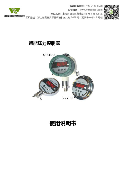
智能压力控制器使用说明书一、概述智能压力控制器是集压力测量,显示,输出、控制于一体的智能数显压力测控产品。
该产品为全电子结构,前端采用带隔离膜充油压阻式压力传感器,由高精度的A/D转换,经微处理器运算处理,现场显示,并输出一路模拟量和两路开关量。
该智能数字压力控制器使用灵活,操作简单,安全可靠。
广泛应用于水电,石油,化工,机械,液压等行业,对流体介质的压力进行现场测量显示和控制。
二、特点◆100标准仪表安装◆4位LED显示,无视值误差.◆控制点现场设定。
◆两路控制点继电器输出◆4~20mA标准信号输出(可选)三、技术参数:量程范围0~100MPa精度等级0.2%F.S.过载能力200%压力类型表压稳定性≤0.1%/年电源电压24VDC/220VAC显示方式0.56"数码管显示范围-1999~9999响应时间<30ms环境温度-20℃~70℃相对湿度≤80%接口材质304不锈钢四、外形尺寸五、安装5.1机械连接:可以通过压力管接头(M20*1.5)(其他尺寸接头可在订货时说明)直接装在液压管路上。
在关键应用场合(如剧烈震动或冲击),压力管接头可以通过微型软管进行机械解耦。
注:量程小于100KPa时必须垂直安装.5.2电气连接为了防止电磁干扰的影响应注意以下事项:●线路连接尽量短●采用屏蔽线●尽量避免直接接近引起干扰的用户装置或电器和电子装置的接线●若用微型软管安装,壳体必须单独接地六、接线红V+黄V-橙OUT+白OUT-蓝ON1绿COM1棕ON2灰COM2七、设置功能AL1H 此值为开关1吸合值AL1F 此值为开关1释放值AL2H 此值为开关2吸合值AL2F 此值为开关2释放值FILt 此值为显示滤波系数,防止因压力波动导致显示跳动。
滤波系数越大,显示越稳定,但越滞后。
3~10可选END 保存退出注:开关点由吸合值和释放值组态决定,吸合值大于释放值时为上限报警输出(常开功能),吸合值小于释放值时为下限报警输出(常闭功能)吸合值与释放值的差值为开关点的回差。
NAMCO 18型杠杆开关控制器说明书
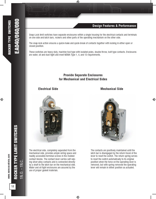
• 1 No. EA080-11100 Snap-Lock Switch • 1 No. EL010-53420 Operating Lever Assembly
Operational Data
CCW
D
CW
D
C
C
AA
BB
Can be furnished with standard and style 1 mountings.
A. Pre-Travel ....................................... 10° B. Differential Travel ............................. 8° C. Recommended Travel .................... 13° D. Total Travel .................................... 38° E. Max. Torque During Pre-Travel 14 Lb-In F. Max. Torque at Total Travel ..… 38 Lb-In G. Weight: ...................... Approx. 2.3 Lbs.
Provide Separate Enclosures for Mechanical and Electrical Sides
Electrical Side
消防泵控制器使用说明书
电动消防泵控制器使用说明书一、概述:电动消防泵控制器是依据国标GB21208-2007、针对国消防泵使用的实际情况开发的一种专用、智能型控制器。
二、功能特点:1.功能描述1.1 系统状态的实时显示:当前使用的电源类型、泵状态、电压状态、电流状态以及后备电源类型;1.2 参数可设置:过压、欠压、系统密码、消防泵参数、ATSE自复延时时间、消防泵自动停止时间、消防泵类型、后备电源类型、时间日期、周测试时间等可以同过面板上的按键进行设置;1.3 系统故障报警:当出现过压、欠压、断相、错相、堵转、ATS切换失败、通信失败、泵状态异常等故障时,通过显示屏界面实时提示、蜂鸣器鸣叫、声光报警器以及led灯点亮的方式进行报警;1.4 周测试功能:设定好测试时间后,系统自动每周测试一次消防泵,并可自动判别消防泵能否正常启动;1.5 电源切换功能:当一路电源出现故障时,自动切换到另一路电源;1.6 实时采集、显示常用和备用电源的三相电压及干路电流;1.7 泵异常情况处理:能自动识别泵异常启动、异常停止;1.8 泵的紧急启动和紧急停止功能:出现紧急情况时,可对消防泵进行紧急启动和停止;1.9 泵的启动互锁:泵手动启动或紧急启动时,系统在软件和硬件上采用了互锁控制,保证任何时候只有一个泵运行;1.10当发生过载、堵转或短路情况时,系统会按照标准要求进行保护;1.11日历功能:显示当前的时间,并可随时修改;1.12 具有远程启动和远程报警功能。
1.13 具有软件复位功能;1.13 带有485通信接口,可通过该通信接口对各参数进行设定和修改,也可进行远程监测和控制(此功能有待完善)。
2.特点2.1通过高亮的LED灯显示故障,保证火灾发生时,人能在烟雾中清楚识别;2.2系统操作有A、B两种操作级别,手动和外部操作等A操作级别高于自动操作等B操作级别;2.3控制发电机的继电器与常用电源联锁,保证常用电源出现故障后,系统自动启动发电机;2.4控制器外部装有手柄和按钮,操作人员可以很方便的进行柜外操作;2.5自动定期检测消防泵和线路的好坏,可有效保证火灾发生时不出现泵不能启动的情况;2.6清晰迷离的人机界面,采用192*64大屏幕液晶中文显示,设置参数可以很方便的通过按键进行操作;2.7采用AC23级别的隔离开关,可在柜外进行带电操作;2.8各继电器的输出和开关的接线进行了互锁设计,保证不会同时启动两台消防泵;2.9控制器采用特种电线进行接线,使控制柜具有体积小、结构紧凑、安装方便、电线使用寿命长等特点;2.10采用电机保护型的断路器,对泵出现的短路故障能进行实时保护;2.11时间日期的设置能自动判断是否越界;2.12柜外装有模拟开关,可方便地演示控制器的电源切换功能;2.13火灾发生时,自动退出测试模式,保证了“消防优先”的原则;2.14大功率消防泵可以采用降压启动的方式,减小泵启动时对电网的冲击;2.15只需简单地更换直接启动或降压启动装置,就可实现消防泵控制器两种启动方式的转换三、主要技术指标:1.符合标准GB16806-2006 消防联动控制系统GB21208-2007 低压开关设备和控制设备-固定式消防泵驱动器的控制器2.设定技术参数说明:ATSE切换延时时间:两路电源均正常时,从备用电源切换到常用电源的延时时间;泵自动停止时间:泵自动运行后,自动停止所需的延时时间;3.主要器件参数4.其他参数工作电源:三相四线制,相电压AC220V MCU控制部分电源功耗:<1W工作温度/存储温度:-5℃~45℃液晶分辨率:192*64防护等级:IP31二次电流输入:5A/2mA四、安装接线:1、安装注意事项1.1电气环境■外部接线时,注意强电信号与弱电信号分开走线;■输入电源的电压波动围必须小于仪表的容限,尤其是在用户定制电源的情况下;1.2气候环境■周围环境没有滴水,气温不超过-5℃~45℃,且24h平均温度不超过+35℃;■安装地点海拔不超过2000米;■当水压驱动控制器用于户外时,管道中的水温不低于+4℃;■相对湿度<90%;1.3运输与存储环境■本产品运输时,需在包装条件下进行,运输和拆封过程中不应收到剧烈震动和冲击。
消防调试---FC18调试手册V02.0
FS18 火灾报警系统调试维护手册FS18火灾报警系统调试维护手册FD18 现场设备FC18火灾报警控制器(联动型)JB-TGZL-FC18R火灾报警控制器(联动型)版本:V02.0FS18 火灾报警系统调试维护手册西门子西伯乐斯电子有限公司保留此手册最终解释权。
任何单位和个人未经授权不得发布或者传播此手册内容。
本调试维护手册适用于西门子FS18火灾报警系统的调试和维护。
本手册中的常规条款也可在线或致电索取。
西门子西伯乐斯电子有限公司将尽力避免文中的印刷及图片错误,但并不对可能出现的疏忽承担责任。
文中提到的产品参数以及适用说明如有更新,恕不另行通知。
西门子西伯乐斯电子有限公司版权所有,Copyright © 2006-2009FS18 火灾报警系统调试维护手册目录1概述 (1)2安全 (3)2.1安全提示 (3)2.2安全操作规程 (3)3系统设计 (4)3.1FS18系统示意图 (4)3.2探测回路拓扑结构 (5)3.3隔离模块应用规则 (6)3.4负载因子计算 (8)3.5传输距离 ····································································································································错误!未定义书签。
(完整word)变压器风冷智能控制柜操作说明书
ZH-BFKM18/6QJ 型变压器风冷智能控制柜操作说明书保定中恒电气有限公司Bao Ding Zhong Heng Electric CO。
, LTD目录一、型号说明∙∙∙∙∙∙∙∙∙∙∙∙∙∙∙∙∙∙∙∙∙∙∙∙∙∙∙∙∙∙∙∙∙∙∙∙∙∙∙∙∙∙∙∙∙∙∙∙∙∙∙∙∙∙∙∙∙∙∙∙∙∙∙∙∙∙∙∙∙∙∙∙∙∙∙∙∙∙∙∙∙∙∙∙∙∙∙∙∙∙∙∙∙∙∙∙ 2二、使用条件∙∙∙∙∙∙∙∙∙∙∙∙∙∙∙∙∙∙∙∙∙∙∙∙∙∙∙∙∙∙∙∙∙∙∙∙∙∙∙∙∙∙∙∙∙∙∙∙∙∙∙∙∙∙∙∙∙∙∙∙∙∙∙∙∙∙∙∙∙∙∙∙∙∙∙∙∙∙∙∙∙∙∙∙∙∙∙∙∙∙∙∙∙∙∙∙ 2三、技术参数∙∙∙∙∙∙∙∙∙∙∙∙∙∙∙∙∙∙∙∙∙∙∙∙∙∙∙∙∙∙∙∙∙∙∙∙∙∙∙∙∙∙∙∙∙∙∙∙∙∙∙∙∙∙∙∙∙∙∙∙∙∙∙∙∙∙∙∙∙∙∙∙∙∙∙∙∙∙∙∙∙∙∙∙∙∙∙∙∙∙∙∙∙∙∙∙ 3四、功能特点∙∙∙∙∙∙∙∙∙∙∙∙∙∙∙∙∙∙∙∙∙∙∙∙∙∙∙∙∙∙∙∙∙∙∙∙∙∙∙∙∙∙∙∙∙∙∙∙∙∙∙∙∙∙∙∙∙∙∙∙∙∙∙∙∙∙∙∙∙∙∙∙∙∙∙∙∙∙∙∙∙∙∙∙∙∙∙∙∙∙∙∙∙∙∙∙ 3五、控制操作程序∙∙∙∙∙∙∙∙∙∙∙∙∙∙∙∙∙∙∙∙∙∙∙∙∙∙∙∙∙∙∙∙∙∙∙∙∙∙∙∙∙∙∙∙∙∙∙∙∙∙∙∙∙∙∙∙∙∙∙∙∙∙∙∙∙∙∙∙∙∙∙∙∙∙∙∙∙∙∙∙∙∙∙∙∙∙∙∙∙∙ 4六、故障报警及冗余控制程序∙∙∙∙∙∙∙∙∙∙∙∙∙∙∙∙∙∙∙∙∙∙∙∙∙∙∙∙∙∙∙∙∙∙∙∙∙∙∙∙∙∙∙∙∙∙∙∙∙∙∙∙∙∙∙∙∙∙∙∙∙∙∙∙∙∙∙∙∙∙ 6七、检修操作注意事项∙∙∙∙∙∙∙∙∙∙∙∙∙∙∙∙∙∙∙∙∙∙∙∙∙∙∙∙∙∙∙∙∙∙∙∙∙∙∙∙∙∙∙∙∙∙∙∙∙∙∙∙∙∙∙∙∙∙∙∙∙∙∙∙∙∙∙∙∙∙∙∙∙∙∙∙∙∙∙∙∙∙9注:在使用风冷控制柜前,检修操作注意事项一定要认真阅读!一、型号说明二、使用条件2。
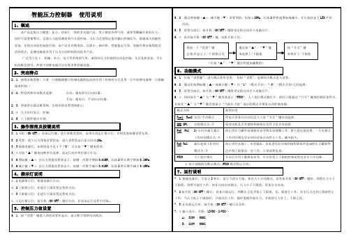
智能压力控制器使用说明
8、电气原理图9、故障排除说明当出现以下显示字符,会直接关闭智能压力控制器的自动控制功能,运行指示灯灭,同时关闭设备。
显示字符出现的原因解决方法ER0表示所配的接触器损坏更换接触器ER1/ER2表示表自身元器件有损坏在保修期内可到经销商以旧换新ER 3“自检模式”开启状态下,设备运行后,原因①:在设定的检测时间后,没有增加压力所出现的保护字符。
原因②:在设定的检测时间内,检测到设备出现问题,比如:电机的堵转和缺相以及管子崩裂。
①同时按住“▲”与“▼”键恢复,继续增加压力便可正常工作②检查设备是否坏了ER 4“24小时内最大累计工作时间模式”开启状态下,可能①:所设的时间数<实际用水次数的累计时间所出现的保护字符。
可能②:设备出现问题,比如:压力罐单向阀长时间使用后出现损坏。
①只要同时按住“▲”与“▼”键便可恢复控制功能,可重新增加一下此模式所设的时间数,设备会照常正常工作②检查设备是否坏了ER 5“设备最大连续工作时间模式”开启状态下,可能①:所设的时间数<实际工作连续时间所出现的保护字符。
可能②:设备出现问题,比如:因井水抽干、水管漏水、水泵老化而导致的扬程降低所造成的压力罐始终达不到上限值。
①只要同时按住“▲”与“▼”键便可恢复控制功能,可重新增加一下此模式所设的时间数,设备会照常正常工作②检查设备是否坏了10、使用注意事项10.1严禁超量程使用,特殊过载请于订货前确认;10.2注意连线方法,错误的连接有可能损坏内部电路;10.3严禁用硬物深入感压孔,接触压力膜片;10.4用户不得自行拆卸;10.5如工作异常,请联系我公司售后技术人员指导调试。
智能压力控制器使用说明书。
JB-TGZL-FC18R型火灾报警控制器(联动型)操作说明书c_zh

Building Technologies
JB-TGZL-FC18R 型火灾报警控制器(联动型)操作说明书
目录ቤተ መጻሕፍቲ ባይዱ
第一章 系统简介······································································································································································3 1. 特点 ·················································································································································································· 3 2. 性能参数··········································································································································································· 4 3. 外形尺寸··········································································································································································· 5 4. 兼容设备目录···································································································································································· 5 5. 系统结构··········································································································································································· 6
智能压力控制器使用说明

智能压力控制器使用说明
一、产品概述
二、产品特点
1.精确测量:智能压力控制器采用高精度的传感器技术,测量结果准确可靠。
2.显示直观:采用液晶屏显示结果,数字显示清晰,便于操作人员查看。
3.控制灵活:可以根据需求设置控制范围和控制方式,实现自动控制或手动控制。
4.报警功能:当压力超出设定范围时,智能压力控制器会发出声音或闪灯报警,提醒操作人员采取相应措施。
三、使用步骤
1.安装:将智能压力控制器固定在所需控制的设备或管道上,并连接好电源和传感器。
2.设置参数:根据实际需求,设置合适的测量范围、控制范围和控制方式。
3.校准:在开始使用前需要对智能压力控制器进行校准。
校准方法可以根据用户手册进行操作。
4.启动:打开电源开关,智能压力控制器即可开始工作。
液晶屏上会显示当前压力数值。
5.监测:通过观察液晶屏上的压力数值,可以实时监测压力的变化情况。
6.控制:如果需要对压力进行控制,可以根据设定的范围和方式进行
调整。
如果超出设定范围,控制器会自动发出警报。
7.关机:使用结束后,将压力控制器的电源开关关闭。
四、注意事项
1.使用前请仔细阅读产品说明书,了解产品的特点、功能和操作方法。
2.在安装和使用过程中,请确保设备和管道的连接牢固,以免发生泄
漏和其他意外事故。
3.在校准时,请参考产品说明书中的操作步骤,严格按照要求进行。
5.请勿随意拆卸或改装压力控制器,以免损坏设备或影响正常使用。
智能正压型防爆控制柜使用说明书

目录序言 (1)一产品选型说明 (2)二产品结构概述 (3)三产品的工作原理 (3)四产品的安装 (3)五产品的调试 (5)六产品的维护 (7)序言为了能让用户正确选型、安装、使用本设备,特编写本《说明书》供用户参阅。
本《说明书》是我公司结合产品的实际情况,对其结构、工作原理、安装、调试、操作、维护等作了详细介绍。
用户在安装使用前,请务必认真阅读本《说明书》,严格按《说明书》要求进行操作,否则,因此而造成的质量事故,我公司概不负责。
一产品选型说明型号含义PXK□□/□/□T特殊要求(无要求可不注)外形尺寸:宽X高X厚(mm)S:联锁(用户配电与正压自控系统低压联锁)(不要求可不注)t:通风型b:补偿型X:箱式Q:琴台式G1:柜式1(上下结构)G2:柜式2(左右结构)正压型防爆配电柜二产品结构概述本产品适用于石油化工、海上钻井平台、冶金、医药、轻工、纺织、食品、生物工程、航天航空工程以及军事设施等工厂,具有ⅡA、ⅡB、ⅡC级,温度组别为T1~T4的爆炸性气体或蒸气环境中;海拔高度不超过2000米;25℃时,相对湿度95%以下;工作环境温度-20℃~+40℃之间。
可根据用户要求安装各种普通的检测仪表、分析仪表、显示仪表、微电脑触摸屏以及普通电器元件,对用户内装电器元件基本不受限制。
配电柜由柜体、自控系统、布气系统、报警系统、用户配电系统组成;柜体由正压腔和副腔组成,正压腔内装用户配电系统元件及部分自控系统的防爆元件;副腔内装自控系统、报警系统及用户的进出电缆。
本配电柜采用Q235钢板或不锈钢焊接而成,对其各接合面都经过了特殊的密封处理。
本配电柜进气方式为通风型,即不间断连续供气,正压腔内装元件的工作热量可随气路带走,具有很好的散热效果。
三产品的工作原理配电柜在自动控制系统的控制下,通入保护气体,正压腔内压力高于正压腔外的压力,形成微正压的安全小环境,从而阻止了可燃性危险气体进入正压腔内,保证内装普通仪表和电器元件的安全运行。
AI-518518P型人工智能温度控制器使用说明书(V7[1].1)
![AI-518518P型人工智能温度控制器使用说明书(V7[1].1)](https://img.taocdn.com/s3/m/f36d46c305087632311212e2.png)
使用说明书 (V7.1)一、概叙 (3)(一)主要特点 (3)(二)型号定义 (4)(三)模块功能的进一步说明 (7)(四)仪表维护 (9)二、技术规格 (10)三、仪表接线 (12)四、面板说明及操作说明 (16)(一)显示状态 (17)(二)基本使用操作 (19)(三)AI人工智能调节及自整定(AT)操作 (20)(四)程序操作(仅适用AI-518P型) (22)五、功能及设置 (23)(一)参数功能说明 (23)(二)部分功能的补充说明 (38)六、常用工作方式 (41)(一)位式调节/报警仪表 (41)(二)温度变送器/程序给定发生器 (42)(三)AI人工智能调节器 (43)七、AI-518P程序型仪表补充说明 (44)(一)功能及概念 (44)(二)程序编排 (46)一、概叙(一)主要特点●输入采用数字校正系统,内置常用热电偶和热电阻非线性校正表格,测量精确稳定。
●采用先进的AI人工智能调节算法,无超调,具备自整定(AT)功能。
●采用先进的模块化结构,提供丰富的输出规格,能广泛满足各种应用场合的需要,交货迅速且维护方便。
●人性化设计的操作方法,易学易用。
●全球通用的100~240VAC输入范围开关电源或24VDC电源供电,并具备多种外型尺寸供客户选择。
●通过新的2000版ISO9001质量认证,品质可靠。
●产品经第三方权威机构检测获得CE认证标志,抗干扰性能符合在严酷工业条件下电磁兼容(EMC)的要求。
注意事项●本说明书介绍的是V7.1的AI-518/518P型人工智能温度控制器,本说明书介绍的功能有部分可能不适合其他版本仪表。
仪表的型号及软件版本号在仪表上电时会在显示器上显示出来,用户使用时应注意不同型号和版本仪表之间的区别。
务请用户仔细阅读本说明书,以正确使用及充分发挥本仪表的功能。
●AI仪表在使用前应对其输入、输出规格及功能要求来正确设置参数,只有配置好参数的仪表才能投入使用。
Xyle 水泵控制器说明书

FEATURES ArrayQuickly and easily calibrates any submersible or centrifugal pump to jobsite conditions (voltage and current).Available installed in new QD style, NEMA 3R Rainproof (outside) enclosures or shipped loose for installation in existing control panels. Single phase units work with the hand held Informer for simple, fast troubleshooting and system diagnostics.Available in single and three phase models.Insider Plus models fit in Goulds Water Technology, Pentair and Franklin Electric Quick Disconnect type control boxes from ½ - 1 HP. Insider Plus units include a Fiber Optic Kit as standard. It is used to signal the optional Informer.Protect against dry wells, low and high voltage, over and under current, rapid cycling, jammed pump, dead heading (flow restriction).Automatic reset selectable, 2-225 minutes or can be set on manualreset.Adjustable underload sensitivity on Plus models.PAGE 2APPLICATIONS – SINGLE PHASE ONLY• All submersible pumps, regardless of motor manufacturer• Centrifugal pumps • Circulating pumps • Cooling pumps• Environmental pumps • Residential water wells • Commercial water wells • Irrigation wells• Golf course systemsProtects From:• Dry well (run dry condition)• Flow restrictions (dead head)• Over current (jammed impeller)• Over voltage • Under voltage • Rapid cyclingPUMPSAVER PLUS 111 / 233, 23315 AND 235PLUS MODEL FEATURES• Can be calibrated to specific pump / motor combi-nations and various conditions• Will work with destaged pump models ending in 05R• Infrared LED communication with the INFORMER makes diagnostics simple• “Run Light” indicates the unit is functioning• “Run Light” and “Cal. Light” used as diagnostic indi-cators• Restart delay can be set up to 225 minutes or placed in manual reset mode• Micro-controller provides better accuracy and higher reliability than analog designs• Plus units feature more data storage memory which is viewable using an Informer• Sensitivity adjustment for dry well trip point• Installing PumpSaver Plus equipment on all your installations allows fast, simple troubleshooting with an Informer, eliminate guesswork, get all the data within minutes of arriving at a jobsite.• 5-year warrantyPAGE 3ORDER NUMBERS AND SPECIFICATIONSEnclosure ProvidedOrder No. SymComPhaseNotes HP RangeVoltageYes / NoTypeNew Part Numbers ** 111Insider 111-Insider-P 1115 N/A N/A231Insider 231-Insider-P 1 1/3 - 1 230 N/A N/A 111 111P — 115 No — 1113RL 111P-ENCL 2115 Yes QD – ENCL23315 233P-1.5 — 1/3 - 1½ 230 No — 233153R L 233P-1.5-ENC L 12230 Yes QD – ENCL 233 233P — 1/3 - 3 230 No — 2333RL 233P-ENCL 2 230 Yes QD – ENCL 2353RL50 235P-ENCL + CT0050D10 2, 3 5 - 7½ 230 Yes QD – ENCL 2353RL75 235P-ENCL + CT0075D10 2, 3 10 230 Yes QD – ENCL 2353RL100 235P-ENCL + CT0100D10 2, 3 15 230 Yes QD – ENCL 235 235P 4 5 - 15 230 No — 777KWHP 3—1/3 - 150 200-480 No —** – P signifies the Plus version which has enhanced electronic features and memory.** – ENCL denotes the new, N3R QD Enclosure effective July/August 2009.NOTES:1 – The Insiders install in submersible single phase quick d isconnect control boxes and require no enclosure.2 – Models with a ...3RL suffix are installed in a NEMA 3R enclosure which has both Run and Calibrate lights.3 – Models contain a current transformer.4 – The 235 always requires a Current Transformer, use this model for repairs. Order the 2353RL- _ _ units which contain current transformers for new applications.ACCESSORY ORDER NUMBERSCT0050D10 Model 235, 5 - 7.5 HP , 50 Amp Current Transformer CT0075D10 Model 235, 10 HP , 75 Amp Current Transformer CT0100D10 Model 235, 15 HP , 100 Amp Current TransformerINFORMERHand Held Diagnostic ToolOUTSIDE OF NEW N3R - ENCL INSIDE OF NEW N3R- ENCL WITH A 233P INSTALLEDDimensions: 3.5” deep, 5.4” wide, 8” high Knockouts: ½” (1 each side, 2 bottom)¾” (1 each side, 1 bottom)PAGE 4PUMPSAVER 111INSIDER (115V) AND 231INSIDER (230V)APPLICATION• Submersible pump with a quick disconnect style control boxProtects From:• Dry well (run dry condition)• Flow restrictions (dead head)• Over current (jammed impeller)• Over voltage • Under voltageFEATURES• Fits inside a 3 wire quick disconnect style control box• Can be calibrated to specific pump / motor combi-nations and various conditions• Will work with destaged pump models ending in 05R• Infrared LED communication with the INFORMER makes diagnostics simple• Quick and easy installation – less than 30 seconds • “Run Light” indicates the unit is functioning• “Run Light” and “Cal. Light” used as diagnostic indi-cators• Restart delay can be set up to 225 minutes or placed in manual reset mode• 5-year warrantyINFORMERFEATURES• The Informer is a handheld diagnstic tool designed for use with single-phase PumpSaver models.• The Informer uses an infrared receiver to access data sent from the PumpSaver, which can be helpful for troubleshooting the system.The Informer displays parameters including:• Real-time voltage, current and power • Dry-well and overload trip points • Calibration voltage • Last 20 fault conditions• Voltage, current and power at last fault condition • Highest/lowest voltage and current since last calibration• Line power and dry well trip point • Total pump run time • Number of pump starts• Restart delay setting and time maining (if tripped)• Pump amperageGOULDS WATER TECHNOLOGY CONTROL BOX WITH INSIDER INSTALLEDTo install in CP, QD control box:• Remove the cover from the front of the 3-wire Goulds Water Technology control box.• Remove the yellow wire from the terminal strip at L2.• Remove the black wire between L1 and the capaci-tor.• Press the PumpSaver onto the L1 and L2 terminals.• Reconnect the yellow wire to L2 on the PumpSaver.• Connect the blue wire attached to the PumpSaver to the dual-lug terminal (with the black wire) of the capacitor.INSIDER MOUNTED IN FE, Q-D SUBMERSIBLE CONTROL BOXTo install in FE, QD control box:• Remove blue wire from terminal strip and solid state switch (blue relay) and set aside.• Remove yellow jumper wire from terminal L2.• Install Insider by aligning tabs with upper L2 and L1 tabs and pushing onto tabs.• Connect yellow wire onto L2 terminal on Insider.• Connect blue wire attached to Insider to L1 on solid state switch (blue relay).PAGE 5PUMPSAVER 777KWHPAPPLICATIONSThe Model 777-KW/HP can be used on ANY 3-phase motor. Some examples include: Can Pumps, Mag Drive Pumps, Fractional Horsepower Pumps and Motors, Submersible Pumps and Coal Bed Methane Wells.DESCRIPTIONThe Model 777-KW/HP is a fully-programmable motor and pump protection relay with power-monitoring capability. Voltage, current and power measurements are displayed on the three-digit display, as well as fault information and setpoints. The display simplifies troubleshooting and allows the user to easily and pre-cisely configure setpoints. The Model 777-KW/HP has the following adjustable protection features: STANDARD FEATURES OF 777KWHP• UL Listed as an overload device• Digitally programmable for precise customization • 15 parameters can be programmed for maximum protection• Alphanumeric LED diagnostic display• Last fault memory provides instant troubleshoot-ing diagnostics• Recordable voltage, current, last four faults, KWhusage, and power factor with communicationspackage.• Compact design saves panel space• Agency Listings: UL, cUL, CSA, CE• RS485 communication port• Tamper guard• Remote reset• Surface and DIN rail mount• 5-year warranty• Made in U.S.A.ADJUSTABLE PROTECTION FEATURES OF777KWHP:• Low voltage• High voltage• Voltage unbalance• UL Listed/CSA approved overload• Trip class (5, 10, 15, 20, 30)• Current unbalance• Ground fault• Low power• High power (via network only)• Rapid-cycle timer• Fault/overload restart delay• Underload restart delay• Underpower/overpower trip delayOther user adjustable features include:• CT/loop multiplier so overcurrent and power setpoints can be made in actual amps, kW or HP.• Number of restarts after faults - manual, automatic and semiautomatic options.• Number of restarts after underload - manual, automatic and semiautomatic options• Network addressAdding the optional RS485MS-2W communications module activates the built-in Modbus RTU bus capabilities.PAGE 6PAGE 7WIRING CONFIGURATION BASED ON MOTOR AMPSTYPICAL WIRING DIAGRAM FOR MODEL 777-KW/HP (20-90 AMPS) AND 777-LR-KW/HP (2-9 AMPS)CURRENT TRANSFORMER WIRING DIAGRAM FOR MODEL 777-KW/HP (80-800 AMPS)PUMPSAVER 777KWHP (continued)Dimensions for All 777-KW/HP UnitsSYMCOM RECOMMENDS USING CTs WITH TERMINALS TO SIMPLIFY INSTALLATION.Note: All CTs must be faced the same direction and all CT secondaries must be wired identically, i.e. all X1 terminals enter the main (round) window and returns to H1 terminal after exiting the loop conductor window (rectangle).Every CT secondary must make five passes through the corresponding main conductor window on the Model 777-KW/HP .12-18 AWG Stranded WireCONTACTORCONTACTORCOILCONTROLPOWERSTARTSTOPAUTOTO MOTOR3 ØMOTORPUMPSAVER 111 / 233 TYPICAL WIRING DIAGRAMPUMPSAVER 235 TYPICAL WIRINGDIAGRAM WITH DELUXE CONTROL BOX Xylem, Inc.2881 East Bayard Street Ext., Suite A Seneca Falls, NY 13148Phone: (866) 325-4210 Fax: (888) /gouldsXylem is a registered trademark of Xylem Inc. or one of its subsidiaries. Goulds is a registered trademark of ITT Manufacturing Enterprises LLC and is used under license. All other trademarks or registered trademarks are property of their respective owners.© 2023 Xylem Inc. BCPSAVER R2 March 2023。
FC18风扇控制器用户手册说明书
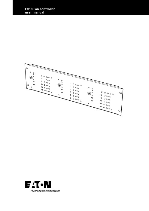
Contents1.INTRODUCTION (1)2.OVERVIEW (1)3.PC SOFTWARE OPERATION (SITE INSTALLER) (2)4.FAN CONTROLLER OPERATION (4)4.1 OPERATION PROCESS (4)4.1.1. MANUAL/AUTO KEY SWITCH (4)4.1.2. KEY SWITCH IN “MANUAL” (4)4.1.3. KEY SWITCH IN “AUTO” (4)4.1.4. FAULT MONITORING (4)4.1.5. RESET (4)4.1.6. TEST LED (4)5.BASIC SYSTEM LA YOUT (5)5.1. FC18 AND CFC301 ON SAME PANEL AND LOOP (5)5.2. FC18 AND CFC301 ON SAME PANEL BUT DIFFERENT LOOPS (5)5.3. FC18 AND CFC301 ON DIFFERENT NETWORKED PANELS (5)5.4. FC18 AND MCOM/MCIM ON SAME PANEL AND LOOP (5)5.5. FC18 AND MCOM/MCIM ON SAME PANEL BUT DIFFERENT LOOPS (6)5.6. FC18 AND MCOM/MCIM ON DIFFERENT NETWORKED PANELS (6)6.FC6 SPECIFICATION (7)6.1. ELECTRICAL SPECIFICATIONS (7)6.2. MECHANICAL SPECIFICATIONS (7)ii FC18 FAN CONTROLLER PR209-166-505-08January 2018 1FC18 Fan controller user manualFC18 FAN CONTROLLER 1.Introduction•The FC18 Fan Controller can be connected to a Cooper analogue addressable fire alarm control panel by means of the comms Loop utilizing only one address.•There are 6 channels per Fan Controller capable of controlling & indicating 6 individual Fans.•All FC18 Fan Controllers are programmed individually by means of the unique easy to use Cooper Site Installer PC software.•Each channel is programmed to an output device and feedback input device that can reside on any loop on any panel on the network to control & monitor the status of the Fan.•The CFC301 which takes 2 addresses on the loop,one for the control output which appears as a ZMU and one for the feedback input which appears as a technical input.•The MCIM can also be used as the feedback input.•The MCOM can also be used as the control output but is limited to 20 per loop.•The MCOM-S can also be used as the control output and is limited to 60 per loop but as it auto-learns and behaves like a sounder it will activate during an evacuation.•The MCOM-FC can also be used as the control output and is limited to 60 per loop but even though it auto-learns as a sounder it will not react to evacuations.Status LED•Power LED (Green) when Fan Control is working normally, the LED on•Fire Activation LED (Red) Operates when fire alarm is received from main panel Controls:Key switch •Auto/Manual key switch: used to select auto or manual control •Select Auto Mode: Green LED. The Fan Control operation is initiated by the state of the Fire Panel •Select Manual Mode: Red LED, The Fan Control operation is controlled by the “Stop/Start” buttons on the individual channels Reset button •Press the button to reset Fan Control. Reset from the main panel will not reset the fan controllerT est LED •Pressing the test LED button will start the control panelself-test Channel 1-6:Start/stop buttons•Start button: press the button, start one device.(Requires to start two channels of the one device)•Stop button: press the button to stop one device.(Requires to stop two channels of the one device)LED indication •ON LED (Red) Activated when the device receives feedback and the Start button has been pressed,otherwise, off.•Fault LED (Amber) Activated when No Feedback has been received after Start has been pressed or Stop button has been pressed but feedback has been received and/or Open Circuit/Short circuit has been reported, otherwise off.•OFF LED (Green) Activated when the stop button has been pressed and No Feedback has been received or no feedback is being received, otherwise off.2.OverviewPR209-166-505-08 January 20182FC18 FAN CONTROLLER 1.Start “Site Installer” program.Figure 1.2.Right click Fan Controller icon (Figure 2).Figure 2.3.Select “Edit Fan Controller” to go into the configuration screen.Figure 3.4.Once in the configuration screen Select “Add Master”.Figure 4.Figure 5.3.PC software operation (Site installer)PR209-166-505-08 January 20183FC18 Fan controller user manualFC18 FAN CONTROLLER 5.Select the output channel, one to six in the configuration screenSelect the “Enabled” in the configuration screen Select the “Loop Mode” in the configuration screen Select the “Confirm” in the configuration screenFigure 6. In the Panel, Loop and Address icons (drop down boxes) across from the Loop Mode, select where the control device you are going to use (CFC301 ZMU, MCOM,MCOM-S, MCOM-FC) is located on the system.In the Panel, Loop and Address icons (drop down boxes) across from the Confirm, select where the feedback device you are going to use (CFC301 Technical Input, MCIM) is located on the system. This only needs to beset if there is feedback from the fan itself.If you use 6 channels, you need to open the 6 channels which will allow you to write 6 rules.6.Select in the configuration screen which cause and effect is needed for the output to activate.Figure 7.GlobalBy addressBy zone groupSelect up to 3 stages to have a combination of different cause and effect results.Figure 8.PR209-166-505-08 January 20184.Fan controller operation 4.1. Operation process4.1.1. Manual/auto key switchA key switch is provided on the front of the Fan Controller to enable/disable the buttons on the front fascia. Thiskey switch must be kept secure and only accessible by authorised personnel who have been trained to use itor by the Fire Brigade. The purpose of this key switch is to prevent unauthorised activations of fans (i.e. by the general public).If the system enters a fire condition that effects the cause and effect rules of the fan controller while it is in manual mode it will not activate the fan control outputs but will remember the fire condition. Once the fan controlleris back in the auto mode it will activate the fan control outputs as per the fire condition and the cause and effect rules.4.1.2. Key switch in “manual”When the fan controller key switch is set in manual mode it enables the Start/Stop buttons for all 6 channels. The fan controller can be placed into manual mode even when the system is in a fire condition. This allows the Customer or the Fire Brigade to manually activate or deactivate the fan associated with each channel of the fan controller. Pressing the “Start” button will cause the control device for that channel to activate which will turn the fan on.If the fan has no feedback mechanism then the “On” LED will turn on automatically when the “Start” buttonis pressed. If the fan does have a feedback mechanism then the fan controller will expect to see the on signal from the feedback device within 25s. If the on signal is received within the time limit the “On” LED will turn on and the “Off” LED will turn off, but if the on signal isn’t received then the “Fault” LED will turn on. If the feedback signal arrives after the 25s it will result in the “Fault” LED to turn off, the “On” LED to be turned on and the “Off” LED to turn off to show the current status of the fan. Pressing the “Stop” button will cause the control device for that channel to deactivate which will turn the fan off. The fan controller expects to see the off signal from the feedback device within 25s. If the off signal is received within the time limit the “Off” LED will turn on and the “On” LED will turn off, but if the off signal isn’t received then the “Fault” LED will turn on. If the feedback signal arrives after the 25s it will result in the “Fault” LED to turn off, the “Off” LED to be turned on and the “On” LED to turn off to show the current status of the fan.4.1.3. Key switch in “auto”When the fan controller key switch is set in automatic mode it disables the Start/Stop buttons for all 6 channels will only allow the channels to be activated by the cause and effect programming of the Fire system.When the Fire system receives a fire alarm signal that effects the cause and effect rules of the Fan Controllerit will turn on the “Fire Activation” LED and activate the associated fan as if someone had pressed the start button for that channel (see manual Key Switch in “manual”for more details).4.1.4. Fault monitoringIf the fan controller receives a fault condition from either the control device or the feedback device (if the fan has feedback) it will result in the “Fault” LED turning on. This also includes short circuit and open circuit conditions between the feedback device and the fan itself.4.1.5. ResetA reset from any panel in the Fire system will not reset the Fan Controller itself but may result in the control and feedback devices being reset. This will require the Fan Controller to be manually reset using the “Reset” button. The key switch must be in the manual position in order for the reset button to work.Pressing the “Reset” button will reset the Fan Control back to its quiescent condition and all output devices will turn off.4.1.6. Test LEDPressing the “Test LED” button in auto or manualmode will cause all of the LEDs to flash 3 times and then return to showing the current state of the fan controller channels.PR209-166-505-08January 20184FC18 FAN CONTROLLER 5FC18 Fan controller user manualFC18 FAN CONTROLLER 5.Basic system layout5.1. FC 18 and CFC301 on same panel and loopFigure 9. 5.2. FC6 and CFC301 on same panel but di erent loopsFigure 10. 5.3. FC 18 and CFC301 on di erent n etworked panelsFigure 11.5.4. FC6 and MCOM/MCIM on same panel and loopFigure 12.PR209-166-505-08 January 20186FC18 FAN CONTROLLER FC18 Fan controller user manual5.5. FC 18 and MCOM/MCIM on same panel but di erent loopsFigure 13. 5.6. FC 18 and MCOM/MCIM on di erent networked p anelsFigure 14. PR209-166-505-08 January 20187FC18 Fan controller user manualFC18 FAN CONTROLLER 6.FC 18 6.1. ElectricalLoop load Minimum Nominal Maximum Quiescent current 310μA EnvironmentalOperating temperature -10°C +60°C Humidity (Non condensing)95%rh External 24 volt supply 18v 24v 28v External current 150mA CompatibilitySuitable for use with Cooper analogue addressable re systems 6.2. MechanicalPR209-166-505-08 January 2018Eaton is a registered trademark.All trademarks are property of their respective owners.Eaton EMEA Headquarters Route de la Longeraie 71110 Morges, Switzerland Eaton.euEaton Eaton Electrical Systems Ltd. Wheatley Hall Road Doncaster South Yorkshire DN2 4NB United Kingdom© 2017 Eaton All Rights Reserved Printed in UK Publication No. PR209-166-505-08 / CSSC-510 Article No.January 2018。
智能压力控制器使用说明
智能压力控制器使用说明智能压力控制器使用说明引言:本文档提供了智能压力控制器的详细使用说明。
智能压力控制器是一种先进的设备,用于监测和控制压力。
通过本文档,您将了解到如何正确操作和配置智能压力控制器,并有效地使用它来控制压力。
1、安装1.1 设备准备在安装智能压力控制器前,确保您已准备好以下设备:智能压力控制器、电源线、压力传感器、连接线缆等。
请仔细检查这些设备是否齐全并且安装正确。
1.2 设备安装1.2.1 将智能压力控制器安装到指定的位置。
确保设备与管道连接牢固,并且无泄露现象。
1.2.2 安装压力传感器,确保传感器的位置靠近需要监测压力的区域。
2、配置与连接2.1 连接电源线将电源线正确连接到智能压力控制器,并确保电源线连接到稳定的电源。
接下来,检查电源线是否安全稳固地连接到设备上。
2.2 连接压力传感器将压力传感器正确连接到智能压力控制器的压力传感器接口上。
请注意,连接线缆应牢固并且无损坏现象。
2.3 配置参数按照设备说明书的指导,正确配置智能压力控制器的相关参数。
这些参数将决定控制器如何工作,并且可以进行个性化的调整。
3、操作与使用3.1 启动设备一旦完成了安装和配置步骤,就可以启动智能压力控制器。
通过按下电源按钮,设备将开始运行。
3.2 数据监测智能压力控制器将实时监测管道中的压力,并通过显示屏显示相关数据。
通过查看这些数据,您可以了解当前管道的压力状况。
3.3 压力控制通过操作智能压力控制器上的按钮,您可以设定所需的压力范围。
一旦达到设定的压力范围,控制器将采取相应的操作来调整压力,并保持在设定范围内。
4、维护与保养4.1 定期检查定期检查智能压力控制器的各个部件,确保其正常运行。
特别注意检查压力传感器和连接线缆的状态,如有损坏或老化,及时更换。
4.2 清洁定期对智能压力控制器进行清洁,确保设备表面无尘或污渍,并保持通风良好。
4.3 注意事项在操作和维护智能压力控制器时,请务必遵循以下注意事项:- 请勿将设备暴露在过温、潮湿或腐蚀性环境中。
WM-18A型系列智能调压器使用手册.PDF

WM-18A型系列智能调压器使用手册一,概述WM-T系列智能调压器,双路可控电压电流输出,可对每路负载上的电压进行独立调节,对每路的负载电压电流通信反馈。
控制器对可控硅采用移相触发方式,改变负载上每个作功波形的有效值,用连续缓慢调压的方式调节加热功率,由于深度电压负反馈的作用,有良好的调整线性,电网波动的影响也减之最小,用精密电流电压互感器作负载电流电压检测。
控制器设计新颖,具有精度高、抗震性强、可靠性好、抗干扰能力强、外形尺寸小、重量轻。
WM-T系列智能调压控制器,采用了国际先进的专用控制双微处理器,集中控制的RS485通信机制,故障自诊断功能使得操控更加方便简洁快速,性价比极高,可广泛应用于吹塑(吹瓶)、吸塑、模具加热、包装机械等机械等设备。
二,主要技术指标1、输出脉冲:幅值不小于3V,宽度不小于50us(20Ω负载时);移相触发最大导通角:不小于150°;2、电压设定范围:0-200V(或指定量程);3、工作环境:温度0-50℃相对湿度不超过85%的无腐蚀性气体场合;4、电源:交流200V±15% 50Hz 。
5、电阻型负载:最大单面电流输出25.0A(例如01号调压器的A面输出电流<=25.0A)6、智能调压器有负载短路或者过流保护功能,负载开路通信提示功能。
三,电器安装1、将输出、电源及电阻负载连线按以下《智能调压器电器系统安装示意图》接妥。
2、智能调压器必须安装在金属的底板上或者散热器上,并注意通风散热良好,以保证智能调压器外壳在任何情况下的温度不超过80℃。
四,使用注意事项1,输入MAX485全隔离通信,通讯协议见《WM-18A型系列智能调压器通信协议》。
2, D3 D2 D1 D0 4个指示灯为该智能调压器的地址指示灯(A面地址 B面是A面加20),上电会显示本机的地址;3, TX为通讯状态指示,有通信时闪烁,没有时熄灭。
ERR接受数据校验指示,如果ERR常亮,表示一直没有接受到正确的数据;4,不得驱动感应炉、升/降压变压器等电感性负载,以防损坏可控硅和控制器;5, 控制器保管时应放在干燥、通风、无腐蚀性气体的地方,而且环境温度和相对湿度符合技术要求;6,控制器在按规定的条件下使用和保管,自出厂日起一年内出现因制造质量而导致的故障,由本公司负责修理。
萨尔曼电子接触压力控制器说明书
CONTROLLERSDesigned and manufactured by Sauermann, the ECM electric contact pressure controller to combine the inherent reliability and accuracy of the liquid column manometer with electronic switching. The operating principle gives unrivalled performance when compared to traditional pressure controllers.The Sauermann ECM electric contact pressure controllers excel where it is necessary to monitor small variations in low pressures of air or gas and where accurate and reliable monitoring is essential. The ECM is widely used in pharmaceutical laboratories, clean rooms and other area’s where good performance is essential.Positive, negative and differential pressure measurement, with the option of 1 or 2 electric contacts on the same scale Electric contacts from 0.5 mm H 2O (5 Pa)Contact rating: 3 A at 230 V - 50 Hz Delay adjustable from 0 to 45 seconds Operation of the contact on rising or falling pressure, by using the inverter functionSimple pressure setting by cursor on graduated scaleVisualization of the pressure on the liquid column and the set pointFEATURES AVAILABLEDelivered empty in cardboard packing with appropriate manometer liquid flask, 2 screws, fixing bolts and Quick Start Guide.TECHNICAL SPECIFICATIONSUF 313-1 AMPLIFIERPHOTO-ELECTRICAL CURSORNot sensitive to other light sources.Red mark on the altuglass cursor , for adjustment of the switching point or of reset point.HOUSINGACCESSORIES• ECM electronic card: power supply 24, 48 or 230 V• Detection cursor for ECM• Connections with security valve type 509SERVICEThe ECM do as not need any particular service.We simply recommend that the indicator liquid is changed every year, to ensure the photo electric cell work properly.F T _E N – E C M – 03/03/21 – N o n -c o n t r a c t u a l d o c u m e n t – W e r e s e r v e t h e r i g h t t o m o d i f y t h e c h a r a c t e r i s t i c s o f o u r p r o d u c t s w i t h o u t p r i o r n o t i c e.。
亚龙YL-218液压说明书

使用说明书浙江亚龙教仪有限公司实验注意事项:1、油泵为三相交流电有正反转,接线时必须注意L1、L2、L3的顺序。
2、油泵的进油压力最好在3MPa以内的范围。
3、一个实验做完后,请先关掉电源,再拔掉快速接头。
4、在做压力继电器实验时,一般将压力继电器调到25档位。
5、按钮模块、电磁阀模块、中间继电器模块为24VDC直流供电。
一、采用节流阀的节流调速回路1.定压节流调速回路本实验装置中进油压力由溢流阀确定,调节节流阀的开口可以方便地改变油缸的运动速度,实验时按图示接好油路、电路,按按钮"SB2"时,油缸伸出,按按钮"SB1"时,油缸缩回。
本实验所涉及到的液压装置有:油缸、单电控二位四通阀、溢流阀、节流阀。
进油调速回油调速SB1KZ11DT油缸SB2KZ1KZ12、变压节流调速回路本试验装置中溢流阀作安全阀使用,系统无溢流损失. 本试验装置中调节节流阀的开口可以方便地改变油缸的运动速度;实验时按图示接好油路、电路,按按钮“SB2”时,油缸伸出,按按钮“SB1”时,油缸缩回。
KZ1KZ1SB21DTKZ1SB1二、采用调速阀的节流调速回路1、定压节流调速回路本实验装置中油缸的速度波动性较节流阀小,实验时按图示接好油路、电路,按按钮“SB2”时,油缸伸出,按按钮“SB1”时,油缸缩回。
本实验的液压装置有:油缸、单电控二位四通阀、溢流阀、调速阀。
该实验与定压节流阀调速的差别在于调速阀调节油缸的速度波动性比节流阀小。
油缸回油调速进油调速油缸SB1KZ11DTSB2KZ1KZ12、变压节流调速回路本实验装置中油缸的速度波动性较节流阀小,实验时按图示接好油路、电路,按按钮“SB2”时,油缸伸出,按按钮“SB1”时,油缸缩回。
KZ1KZ1SB21DTKZ1SB1三、简单的压力调节回路程实验时按图示接好油路、电路,按按钮“SB2”时,油缸伸出,按按钮“SB1”时,油缸缩回,调节溢流阀,压力表可以明显的显示系统压力的变化。
ph18系列说明书新

质量保证本公司提供自销售日起一年内的本机售后保证,但不包括不当使用所造成之损坏,若需要维修或调整,请寄回,但运费需自付,寄回时需确定包装良好以避免运送途中损坏,本公司将免费维修仪器内部的损坏。
(注:电极、标准液属于易耗品,不在保证范围内,本公司将保证电极交付使用时的品质。
)南京宝威仪器仪表有限公司使用说明书工业PH计型号:PH-18用户须知●使用时请遵守本说明书之操作规程及注意事项。
●在使用过程中若发现仪器工作异常或损坏请联系经销商,切勿自行修理。
●为使测量更精确,仪器须经常配合电极进行标定;若您的电极购买时间已近一年或电极存在质量问题,请注意更换。
●执行标定工作之前请将仪器通电预热三十分钟。
●因产品更新换代,本说明书如有变动恕不另行通知。
注意:因PH电极线为特殊专用线,请勿剪接。
若因剪接造成仪表无法标定等其他问题,生产厂家概不负责。
标准缓冲液pH 值对照参考表TEMP℃ 4.00 4.01 6.86 7.00 9.18 10.010 4.00 4.00 6.98 7.12 9.46 10.325 4.00 4.00 6.95 7.09 9.39 10.2510 4.00 4.00 6.92 7.06 9.33 10.1815 4.00 4.00 6.90 7.04 9.28 10.1220 4.00 4.00 6.88 7.02 9.23 10.0625 4.00 4.01 6.86 7.00 9.18 10.0130 4.01 4.02 6.85 6.99 9.14 9.9735 4.02 4.02 6.84 6.98 9.17 9.9340 4.03 4.04 6.84 6.97 9.07 9.8945 4.04 4.05 6.83 6.97 9.04 9.8650 4.06 4.06 6.83 6.97 9.02 9.83仪器实际读值与标准有时会有±1个字的误差-21-pH 电极使用保养PH电极在测量时,应先在正蒸馏水中(或去离子水中)清洗干净,并用滤纸吸干水分,防止杂质带进被测液中,电极的1/3应插入被测溶液中。
AGE说明书
功率因素控制器BLR_CX使用说明书目录1 安装2 参数设定3 调试步骤4 报警功能5 通讯6 OPTION “L”:配置风扇控制和2个目标功率转换功能7 OPTION “LT”:风扇控制和2个由温度控制的目标功率转换8 OPTION “M”:测量值显示功能9 OPTION “K”:两用可编程控制开关10 出厂设置11 接线1 安装同所有的电力设备一样,在安装功率因素控制器时须遵守一定的规范。
当移开面板上的AEG 标牌来调节功能开关和切换开关时,要确保你身上没有带任何的静电电荷。
去除这些电荷可以通过触摸接地的物品,比如通过触摸配电盘的金属外壳。
1)检查控制器的工作电压和测量电压,电源频率以及电流互感器等级满足控制器背面提供的参数等级要求。
2)用两个装配夹子将控制器安装在配电盘中。
3)按照提供的接线图接线。
要注意电流互感器连接线的截面尺寸大小。
我们建议采用长达10米,2.5平方毫米截面的连接线。
一个具备BLR_CX控制器工作电压的集成电压监控器能够确保电路中电容器在主电压降低70%后安全断开。
必须保证控制器的工作电压和接触器的控制电压取自同一相电压。
请使用特定的工具用来连接导线与控制器背部的弹簧接线端。
控制器的金属外壳必须接地。
4)电流采样通道一般是针对电流互感器二次线圈为5A或1A而设置的。
可选择的CT变比适用于”M”模式(增加了数据的显示)2 参数设定在可移动标志牌后面有一个多功能开关H3和两个按钮+,-。
OPTION “L”(风扇控制)有两个额外的切换开关(S1,S2),用来选择四个不同温度门限。
OPTION M(万用表功功能)控制器面板有两个键用来选择切换数据。
通过+/- 按钮来调整控制器参数的大小,通过多功能开关(H3)来选择功能配置。
控制器的出厂参数设置能够简化参数设置。
多功能开关(H3)0 控制器关闭正在运行的程序会在20秒后自动停止。
根据参照投入每个电容器的记录数值来从10-60%选择一个合适值。
- 1、下载文档前请自行甄别文档内容的完整性,平台不提供额外的编辑、内容补充、找答案等附加服务。
- 2、"仅部分预览"的文档,不可在线预览部分如存在完整性等问题,可反馈申请退款(可完整预览的文档不适用该条件!)。
- 3、如文档侵犯您的权益,请联系客服反馈,我们会尽快为您处理(人工客服工作时间:9:00-18:30)。
产品用途:
Tianjin Bily Science and Technology Development Co., Ltd.
广泛应用于水电,自来水,石油,化工,机械,液压等行业,对流体介质的压力进行现
场测量显示和控制。
一、概 述
YX18 智能压力控制器是集压力测量,显示,输出、控制于一体的智能数显压力测控 产品。
该产品为全电子结构,前端采用带隔离膜充油压阻式压力传感器,输出信号由高精度,
低温漂的放大器放大处理,送入高精度的 A/D 转换器,转换成微处理器可以处理的数字信号,
经过运算处理的信号控制两路开关,对控制系统压力进行测控。
该智能压力控制器使用灵活,
操作简单,调试容易,安全可靠。
二、产品特点
■多路开关量(带载能力 1.2A),模拟信号 4~20mA 可选;
■压力控制开关点调节无死区,可在量程范围内任意设定;延滞切换输出时间可自行设定;
■按键调校及现场设置各种参数,操作方便,.更加灵活。
三、仪表参数
3.1 基本参数 工作参数 仪表类型
连接方式 输出功能
YX18-B M20*1.5(可订制) 两路开关量+一路模拟量
电源电压 外电源:24VDC±15%,纹波≤±5%; 220VAC±15%(可选) 触点容量 DC 24V—1A(阻性);AC 250V—3A(阻性) 控制精度 ≤±0.5%FS 控制范围 -0.1~0~0.003~60MPa 过载能力 150% 开关次数 1×10¬7 防护等级 IP65 使用条件 介质温度:-30℃~85℃;
四、仪表选型
型号 BL-YX18 -□ /□ /□ /□ /□ /□
说明
X
小巧型
仪表类型 B
标准型
F
防爆型
测量范围
***
请参考【3.1 基本参数】表格中参数→控制范围
输出类型
**
请参考【3.1 基本参数】表格中参数→输出功能
D 供电形式
A
DC 24V AC 220V
1
螺纹连接 M20×1.5
连接方式
2
螺纹连接 M27×2(需订制)
3
螺纹连接 G1/2
4
法兰连接(需订制)
Tianjin Bily Science and Technology Development Co., Ltd.
防爆等级
N 不防爆 E Exia II CT5(Exd II BT5)
五、外形尺寸
5.1 外形尺寸图(外形尺寸图 1-3)
智能压力控制器
kPa MPa
AL1
AL2
SET
1、小巧型
智能压力控制器 MPa
SET
2、标准型
S32
3、防爆型
六、 设置功能
6.1 开关量输出 智能压力开关有两路开关量输出。
每路开关量输出可以设定 1 个压力开关点和一组开启关 闭延时值。
相应的输出会在开关点的吸合值到达时切换并在压力下降到低于释放值时回复。
6.2 模拟输出 据型号规格: A 系列两路开关量+一路模拟量,带一路模拟 6.3 设置开关点 ●按下“mode”键 ●显示“LOCK” (提示输入密码)
Tianjin Bily Science and Technology Development Co., Ltd. ●按▲或▼键输入密码“1”, ●按下“mode”键确认 ●按▲或▼键上翻或下翻进行菜单选择(AL1H、AL1F、AL1D、AL2H、AL2F、AL2D、END) ●按下“mode”键进入所选菜单。
●按▲或▼键更改设置 ●按下“mode”键确认,若需要,再用▲或▼键选择其他菜单进行修改。
●修改完成后选择“END”菜单,按“mode”键确认保存退出 ●若 30 秒无键按下,则自动退出设置状态,但是不保存所修改的数据。
注:在测量状态下按压 mode 键,显示“LOCK”提示输入模式密码,按▲或▼键输入密码 “1”,按 mode 键确认进入菜单,切换使用▲或▼切换。
菜单为循环结构,可以向上、向 下翻。
在 “END” 菜单下按 mode 键保存退出。
数据查看通过 mode 键,修改通过▲或▼键实 现,确认请再次按下 mode 键。
6.4、错误代码 EEoo------EEPROM 数据校验出错,主要是在开机读取数据时检测。
需要人工查看,重新设 置即可恢复错误。
EEo1------开关输出短路。
出现错误输出关闭且再不控制。
措施:排除短路,重新上电
七、 质保
用户在遵守使用和保护规则条件下,仪表自出厂日期起保修一年.一年后的维修在本公司进 行。
本公司随时欢迎用户来函、来电咨询及提出建议。
。
