车载无线传感器网络监测系统设计(外文原文+中文翻译)
基于无线传感器网络的智能交通监控系统设计
基于无线传感器网络的智能交通监控系统设计1. 引言智能交通系统是信息技术与交通管理相结合的典型应用范例之一。
而无线传感器网络(Wireless Sensor Network,WSN)作为一种新兴的通信网络技术,为智能交通系统的监控与管理提供了更加便捷、高效的解决方案。
本文将针对基于无线传感器网络的智能交通监控系统的设计进行探讨。
2. 无线传感器网络的特点无线传感器网络是由大量分布式传感器节点组成的,这些节点可以采集并处理环境中的信息。
无线传感器网络具有以下特点:2.1 无线通信:传感器节点之间通过无线通信进行数据传输,避免了布线成本高昂的问题。
2.2 分布式处理:传感器节点具备一定的数据处理能力,在传感器节点上完成数据处理,减轻中心节点的负担。
2.3 节能设计:传感器节点通常采用低功耗设计,以延长其使用寿命。
2.4 自组织网络:传感器节点可以自主决策,自组织成网络,实现信息的自动采集与传输。
2.5 地理位置敏感:传感器节点通常具备位置感知能力,可以进行地理位置相关的信息处理。
3. 智能交通监控系统设计的基本架构基于无线传感器网络的智能交通监控系统主要由传感器节点、路由节点和监控中心组成。
传感器节点负责采集路况信息,并通过无线传感器网络传输给路由节点。
路由节点将采集到的数据进行处理和过滤,并将有用的信息传输到监控中心。
监控中心负责数据的接收、处理和显示。
该系统的基本架构如图1所示。
(图1:智能交通监控系统的基本架构)4. 传感器节点设计传感器节点是智能交通监控系统中最基本的组成单元。
传感器节点通常由传感器、嵌入式处理器、无线通信模块和电源模块构成。
4.1 传感器:传感器节点根据交通监控系统的需求选择合适的传感器,如光强传感器、声音传感器、温度传感器等,实时采集路况信息。
4.2 嵌入式处理器:传感器节点中的嵌入式处理器负责传感器数据的处理和分析,将处理后的数据发送给路由节点。
4.3 无线通信模块:传感器节点通过无线通信模块将采集到的数据发送给路由节点,可以选择 ZigBee、Wi-Fi、LoRa等通信协议。
机械毕业设计英文外文翻译51采煤工作面无线传感器网络物理层设计UWB技术
翻译部分英文原文Coal Face Wireless Sensor Network Physical Layer Design BasedOn UWB TechnologyAbstractIn order to guarantee the safety of coal face production, it is necessary to monitor and surveillance face Shearer, scraper transport planes, hydraulic support, transport machines, broken machines etc . At present, it is difficult for the cable transmission mode to adapt to changes in the work site of the coal face. Transmission lines are often damaged and snapped for various factors, we use wireless sensor network (WSN), which is flexible to be placed and extensible, to resolve this problem. This paper discuss the design of the WSN transceiver for coal face with UWB technology. This kind of transceiver has some useful advantage such as low cost, low power consumption, simple structure, easy to implement the design of the hardware, no need to estimate the coal face Channel characteristics. However, detection efficiency is slightly lower, but the error rate can meet the requirement.1.IntroductionCoal face must face the complicated geological conditions and poor working conditions. In order to ensure the safety of production in the coal face, it is necessary to monitor real-time the face Shearer, scraper transport machine, hydraulic support, reprint machine, broken machines and other large equipments. In addition, we must monitor the ground pressure, gas, carbon monoxide, dust and other environmental parameters. At the same time, mobile voice and image communications is required. At present, the signal monitored and derived from the coal face is transmitted by cable. As the face is moving constantly and the going of the coal mining process, all kinds of large-scale iron and steel equipments in the coal face need to be boosted circularly and continually. The shape of the space is constantly changing with the change of the relative position of the equipments. Correspondingly, communication in cable is difficult to be applicable with the working scene changing, so transmission lines is damaged or snapped frequently ,and the coal face mobile voice and image communication is impossible .All these issues cause many latent trouble to the Safety of theproduction. We think wireless sensor network (WSN) is feasible to implement monitoring and surveillance to the coal face, for it has some useful characters of placing flexibly, expanding simply, moving easily and self-organization.2.WSN architecture in the coal faceThe sensor network system structure of the mining Coal face is shown in Figure 1. In this Figure, the sensor nodes send the information of acquistion through one or more jumps to the cluster node, the base station (sink node) is responsible for the collection of data, and transmit them to task management node through up-slot network, task management Node is responsible for the integrated process the data and also issued instruction to sensor networks. The tunnel of coal face is a limited space. Bracket, shearer, transport and other large metal equipments are layout and coal, rocks and other media is a non-uniform restricted space, which all make the transmission channel more complex, fading and multi-path phenomena more serious in the transmission of wireless sensor nodes signal. These are different from sensor networks on the ground. Therefore,the design of transceiver node of it isparticularly important. At present,there are three main technologies ofthe physical layer in wireless sensornetworks: narrow-band modulationtechnology, spread spectrumtechnology and ultra-wideband(UWB) technology. While UWB technology possesses some attractive advantages such as low power spectrum density, low-complexity system, Low sensitivity to the channel fading, better security and so on. Considering the advantages and the characteristics of coal face naturally, we have adopted Impulse radio ultra-wide band (IR-UWB) technology, and the reasons are followed: 1) UWB technology consumes lower power and has lower power spectrum. Low power consumption, low-cost and small size are the most important feature of wireless sensor network nodes. Narrow-band modulation technology, spread spectrum modulation technology generally use sine carrier , IF and RF circuits exist in the systems, so consuming more power than the UWB technology with no carrier.Transmission medium in the coal face is non-uniform, which leading to more transmission loss than wireless communications systems on the ground. Therefore low power consumption becomes particularly important. In the coal face, as WSN node presents zonal distribution, nodes just need to communicate with neighbor-nodes. The WSN system based on UWB, consuming lower transmission power, can meet the requirements and avoid the interference with each other in the narrow-band communications node. In addition, the low power consumption and high penetrating power help to design safe equipment and transmit disaster relief signal. 2) Strong anti-interference ability. In the coal face, electrical and mechanical equipment has narrow distribution. When equipment starts or stop, electrical sparkle may cause a lot of electromagnetic interference. So good anti-interference capability is strongly required in the wireless communication. 3) Good Anti-interference to multi-path ability. Coal face has some inherent characters, such as narrow space, more types of media, a multi-path intensive channel, while IR-UWB can be applied to this complicated environment with its advantages: narrow Pulse width, small pulse duration ratio, high multi-path resolution, strong anti-multi-path and fading Capacity. 4) Simple structure. The characters of IR-UWB, such as no modulation and up/down conversing frequency, simple transmitter structure, lower power consumption, make it more acceptable. According to the complexity of the node and power consumption into considerations, IR-UWB technology is very applicable to the design of the wireless sensor network physical layer. Therefore, compared to narrow-band modulation technology, spread spectrum technology, the wireless communication system based on the UWB technology present a good performance on the energy consumption, robustness, anti-multi-path and anti-noise, and so on.The modulation of IR-UWB are mainly PAM (OOK), PPM and BPM (Bi-Phase Modulation), but the presence of lines spectrum in PAM and PPM not only make ultra-wideband pulse signal difficult to meet a certain spectrum Requirements, but also reduce the power utilization, thereby it increases energy consumption. Several IR-UWB signals in the frequency spectrum are shown in Figure 2 and Figure 3 . As WSN system requires low power consumption, PAM modulation often use OOK method, which has simple structure. But OOK has poor performance on the BER(Bit Error Rate), anti-noise performance of BPMmodulation such as anti-Jitter noise is better. ISI would be intensified if we adopted PPM under the conditions of intensive multi-path environment in the coal face. Therefore, we use BPM forms in the transceiver system of the coal face.A. The design of transmitting systemThe transmitter which adopts BPM forms is shown in Figure 4. The signal distortion, interference and noise brought by the special environment in coal face need encoded protection through channel coding interweave module. Data rate of the original information is lower, which make it difficult to meet the requirements of FCC in the absence of modulation. We need to use spread spectrum code transform the original information which has a larger duration ratio into a smaller duration ratio (nanosecond). Then we can generate BPM pulse signal through the pulse formation circuit, which can meet the requirement of FCC. Finally use filters to optimize BPM signal further to enlarge the spectrum and send it out from the antenna.The system uses Gaussian pulse to be the form of UWB signal. If a wave transmitted is the first order derivative Rayleigh pulse, the signal after sending out through the antenna is transformed to be the second order derivative of the Gaussian pulse in ideal circumstances. In addition, the lower the order of the Gaussian pulse is, the farther the signal can be sent under the same data rate. Here we select the Gaussian doublet, whose hardware circuit is relatively easy to implement and consume lower energy. Although interference of narrow-band communication system is exist in the ground wireless communications, the higher order of the Gaussian is , the better Gaussian narrow pulse shape. But we do not need to consider interference to the other narrow-band communications in the coal face, for so far, wireless communications systems is basically non-existent in the mine's coal face. A second Gaussian pulse shape can be expressed as:()()222222214t t d t t P e dt παπα-⎛⎫==- ⎪⎝⎭ Here,α is used to express the pulse width, Suppose that the input signal is {}k α , each bit is expressed by i a and its cycle is f T .After the channel encoder, every bit of the sequence {}k α kare repeated by N times. The code durationtime is s T , so each bit is composed by N pulse width. If we suppose thepseudo-random sequence of sensors node k is (){}k j C , the length of thesequence is N, the duration of the code slice is The sequence of (){}k j C can bereplaced by ()()()(){}12,,,,k k k k m N C C C C Λ and the ()1k j C =±.The time coordinate of i-th bit in the frame date stream sent by sensor node k is i t .()f k i s c t =t -i T -j T -τ()()()()()()()()()N *k k k m j s c i =-j =1N k k m j s c i=-j=1St =p t d C δt-iT -jT -τ=d C p t-iT -jT -τ∞∞∞∞∑∑∑∑ 21,m i d a =- when 0,1,i m a d ==-when 1,1i m a d ==.We can thinks f c f T =NT ,T =T in practical application.When N=1, the UWB waves and waveform sent are shown in the Figure 5. Waveform in the Figure from the top to the end is the UWB waveform (the waveform of code “0” and the waveform “1”); the waveform generated whenseveral code are send out; UWB waveform when get through band-pass filter.B. The design of receiver systemThe recerver structure is shown in figure 6. The signal received through the receiving antenna will go through the low noise amplifier and filter. Then the amplitude of the signal will be detected using tunnel diodes peak detector. Then we can get a pulse waveform which own longer code duration time when the signal detected after passing through high-pass filter and pulse stretch circuit. The last step is sample and judge.In this design, we make use of the characters of the negative resistance region of tunnel diode. In this region, the current decreases as the voltage is increased. This negative resistance results in a very fast switching time. After detected by the tunnel and passed through high-pass filter and comparator, the signal can be stretched and delayed by RS latch. We can directly sampling and judge the signal, for the width of the signal we get is wider than we first received .The kind of the receiver is different from the method we previously used. Such as, literature 555 tell the technology about relevant receiver. As we know, the general complexity of the relevant receiver, which own integrator circuit and need precision clock, is much higher. Sometimes, general relevant receiver need matching filter according to channel model parameters, which can be required by channel estimation. Because channel characteristics under the mine well are extremely complex, the possibility to use channel estimation is small. In addition, the receiver does not need ADC conversion devices, for the comparator has fixed the position of the code “0”and”1”.Furthermore, the code stretched has a relative longer duration time, which do not need higher judgment pulse precision. Therefore, in the whole, the receiver does not need complicated channel estimation and ADC conversion devices, which make the energy-consumption and complexity much lower. But we can not ignore the disadvantage of this kindof receiver; it has bigger signal fading, lower detection efficiency.C. Anti-noise performance of BPMThe propagation environment of the coal face belongs to dense multi-path. And the theoretical channel model we referred to is proposed by combining Saleh-Valenzu channel model, which is the foundation, and the characteristic of the coal face under the mine. Suppose the discrete pulse response is()h t, r(t) isir t=s t*h t.the signal received by one node. Then , ()()()iThe distance between receiver and transmitter is about 5-8 meters, which can satisfy the requirement of the distribution of the nodes in the coal face. The code duration time is 25ns, the duration time of GASSION waves is80ps. Under this conditions , we can get the curve, just as shown in the Figure 8.In fact, when we carried out the experiment of BER test, the performance shown in Figure 8 is not easy to be seen because of the complexity of the channel character. According to the research result, the performance of anti-noise became abnormal, such as the fading of the signal is not in proportion to the distance and the amount of the path increase and decrease in a large scale. Because the relevant coefficient of transmitted waves of the BPM is passive relevance when we adopted relevant receiver, the performance of anti-noise ofBPM in relevant receiver is superior to PPM and OOK. Take the structure simplification of the receiver and the special character of the coal face into consideration, BPM is preferable in the whole,ever if the receiver we discussed in this paper is not superior to the relevant receiver on the anti-noise performance.3.ConclusionBecause of the limited space of a non-uniform medium and the complicated channel character in the coal face, the choice of the model we send and receive the signal is extremely important. Taking into account that BPM do not have discrete spectrum when “0” and ”1” emerged in a same probability, if not, the amount of discrete spectrum is small, which is attractive to WSN system, for the low energy consumption is strongly required. Therefore, the communication mode can be used in the coal face. The Gaussian doublet, which can meet the requirement of FCC, is used to send the source signal. Take the complexity of the transmission channels, the receiver use non-coherent receiving method, use tunnel diode to detect signal, execute sampling and judgment after the signal go through the comparator and stretch circuit. This Method does not need channel estimation and ADC circuits, higher pulse sampling accuracy, which together decides the probability to simplify the structure of the receiver greatly. However, the method of receiving has a greater attenuation and bad anti-noise performance than the traditional relevant receiver. But let’s takes every important fac tor into consideration, the receiving method is suitable for the special environment of the coal face.中文译文采煤工作面无线传感器网络物理层设计UWB技术摘要为了保证安全生产的工作面,监测和监视采煤机,刮板运输机,液压支架,运输机械,破碎机等是必要的。
Connecting Wireless Sensornets with TCPIP Networks 翻译

基于TCP/IP网络的无线传感网连接Adam Dunkels1, Juan Alonso1, Thiemo Voigt1, Hartmut Ritter, Jochen SchillerSICS Technical Report T2003: 20ISSN 1100-3154ISRN:SICS-T--2003/20-SE摘要:无线传感器网络是由许多小的无线传感器节点共同组成的,该网络内的各个小节点共同收集信息。
通常这样的网络不能完全孤立地运作,必须连接到外部网络,进行监测和控制连接。
在TCP/IP协议中,该互联网协议组合,已用于标准的大型网络,而且传感器网络能够连接到TCP/IP 网络中。
在本文中,我们讨论三种方式用于连接TCP/IP网络的传感器网络:代理服务器体系结构、容迟网络和TCP/IP传感器网络。
最后我们得出结论,该方法在某种程度上的正交和组合是可行的。
但对于TCP / IP传感器网络,除了目前有些问题仍需要进一步研究之外,TCP/IP网络是一个可行的协议传感器网络。
一. 引言无线传感器网络是一种基于多个小型无线传感器节点共同组成的信息采集模式。
这种传感器节点,体积小而且价格低廉,通常由一个或多个传感器、短程无线电收发器和一个小的微控制器组成,在电池供电的情况下就可以工作。
传感器网络部署设计方案都比较大,其中每个网络由数百甚至数千个传感器节点组成。
在这种部署方案中,每个传感器单独配置节点通常是不可行的,因此节点的自身配置是很重要的。
节能也很关键,尤其是在几乎很难更换传感器电池的情况下。
因此电池的保养也很重要,应该尽量避免更换电池。
大多数传感器网络程序的目标是监测或检测异常现象。
比如建筑环境控制、野生生物栖息地监测[17]和森林火灾监测[ 24 ]。
对于这样的应用,传感器网络不能在完全隔离的环境中工作,必须有一个监测实体的方式,以获得所产生的数据的传感器网络。
通过连接传感器网络现有的网络基础设施,如全球互联网,局域网,或私人网络,远程访问的传感器网络可以实现。
智能小车无线环境监测系统设计
智能小车无线环境监测系统设计彭倩;吴祎【摘要】Temperature and humidity,light intensity and smoke data playsan important role in industrial production workshop and warehouse cargo maintenance,aiming at the high operating costs and information feedback lag of traditional wired monitoring method,this paper designs a intelligent car wireless environment monitoring system based on LabVIEW.TheSTM32F103RCT6 controller can upload the multi-channel environmental data and transfer the data via the wireless communication moduleNRF24L01,the system switches automatic tracking and manual control mode of intelligent car in the host computer through virtual instrument software,the intelligent car system can be autonomous and high efficiency forward,backward,left and right and obstacle avoidance,While the host computer monitoring interface collects sensor data through the wireless communication module,it also has function for each datadisplay,storage,alarm and so on.Test results show that,the system can effectively and accurately reflect the change in environmental data,which can facilitate a long data collection,transmission and analysis,at the same time can effectively improve the level of real-time monitoring on workshop and warehouse,and has a certain practical and promotional value.%温湿度、光强及烟雾数据的监测在工业生产车间、仓库货物维护中尤为重要,针对传统有线监测方式运行成本高及信息反馈滞后等不足,设计一种基于LabVIEW的智能小车无线监测系统;由下位机STM32F103RCT6控制器对多路环境参数进行数据采集,通过NRF24L01无线通信模块对数据进行传输,利用LabVIEW虚拟仪器软件在上位机对智能小车进行自动寻迹和手动控制模式切换,可实现智能小车高效率的前进、后退、左转及右转,自主避障等动作,同时通过无线通信模块将小车上的各个传感器数据采集到上位机监测界面,实现显示、存储、报警等功能.测试结果表明,系统能有效准确地反映环境数据变化,便于长时间实时的对环境数据进行采集、传输与分析,可有效提高对车间、仓库的实时监测水平,具有一定的实用推广价值.【期刊名称】《计算机测量与控制》【年(卷),期】2018(026)006【总页数】4页(P35-37,116)【关键词】智能小车;环境监测;虚拟仪器;无线通信【作者】彭倩;吴祎【作者单位】西安科技大学电气与控制工程学院,西安710054;中国移动通信集团设计院有限公司陕西分公司,西安710065【正文语种】中文【中图分类】TP2420 引言近几年我国工业的迅速发展对工业生产车间和仓库中的环境信息监测提出了更高的要求。
传感器外文翻译
毕业设计(论文)外文文献翻译院系:光电与通信工程年级专业:12电子信息工程姓名:刘燊学号:1106012133附件:Advances in Sensor Technology Development指导老师评语:指导教师签名:年月日——摘自夏伟强,樊尚春传感器技术的的新发展仪器仪表学报传感器技术的新进展传感器技术是新技术革命和信息社会的重要技术基础,是一门多学科交叉的科学技术,被公认为现代信息技术的源头。
近些年,传感器技术发展很快,取得了许多新进展,尤其在气体传感器、生物传感器、视觉传感器等方面取得了很多进展。
美国麻省理工学院华人科学家张曙光领导的研究小组借助一种特殊溶液,成功地找到了大规模制造嗅觉感受器的办法;同样是麻省理工学院的研究人员利用气相色谱-质谱技术感受识别气体分子,研制出一种能对微量有毒气体做出强烈反应的微型传感器;俄罗斯科学家以从一种普通蘑菇中提取的混合物为原料,与压电石英晶振构成谐振式传感器,能够探测空气中含量极低的酚成分;日本科学家研制出能快速识别流感病毒纳米传感器,有望以纳米技术为快速识别流感病毒、乙型肝炎病毒、疯牛病病原体和残留农药等物质提供新手段;西班牙巴塞罗那自治大学研制出新型缩微DNA分析传感器,这种传感器能将分析 DNA链的时间缩短到几分钟或几小时,智能仪器与传感器技术、空间生物智能传感技术。
可以在亲子鉴定到检测遗传修饰食物的一系列化验中应用,此外还能确定新药的遗传毒性;美国国家标准与技术研究院研发出一种超灵敏微型核磁共振(NMR)传感器,该微型传感器与微流体通道并列置于一个硅芯片之上,这项技术将核磁共振的探测灵敏度提升到一个新的台阶,将在化学分析中具有广泛的应用前景。
我国传感器技术虽然与国外相比还有很大差距,但近两年也取得了一些进展和突破,诞生了一些新产品,有些在国家重大型号工程中获得应用。
如资源环境技术领域中的环境监测及环境风险评价技术、大气复合污染关键气态污染物的快速在线监测技术和大气细粒子和超细粒子的快速在线监测技术,海洋技术领域中的海洋水质污染综合参数在线监测技术和海洋金属污染物现场和在线监测技术等。
车载导航监控终端无线上网的设计与实现
Abstract:This paper presents Nuvoton Technology M0516processor as the core and the general packet radio service (GPRS)module SIM900composed of wireless Internet access systems.With controlling SIM900 module complete car navigation monitor terminal with an Internet connection through AT commands,the vehicle terminal exchange informa- tion with the server.Users can be conveniently and smoothly check vehicle location and condition information,the server can also monitor improper driving behavior of the vehicle and the alarm information,realizing the vehicle navigation and surveillance services. Keywords:vehicle terminal;M0516;GPRS;AT command
— 44 —
中国科技核心期刊
TCP/IP 协议,使得 无 线 数 据 的 传 输 变 得 更 加 轻 松,更 容 易扩展功能。
1 车 载 导 航 监 控 系 统 总 体 及 通 信 通 道
车 载 导 航 监 控 管 理 系 统 包 括 监 控 中 心 服 务 器 、用 户 查 询命令终端、车载 终 端 组 成。 各 个 部 分 以 服 务 器 为 中 心, 通过 GSM/GPRS网络以及Internet网络组织起来配合工 作,完成车辆实时导航监控管理等功能。系统 总 体 结构框 图如图1所示。
面向智能城市的无线传感器网络监测与管理系统设计
面向智能城市的无线传感器网络监测与管理系统设计智能城市是指通过信息技术与物联网技术的应用,使城市基础设施更加智能化、高效化和可持续发展的一种城市发展模式。
无线传感器网络(Wireless Sensor Networks,WSN)作为智能城市中的重要组成部分,具有广阔的应用前景和市场潜力。
因此,设计一套面向智能城市的无线传感器网络监测与管理系统是非常必要和重要的任务。
一、系统概述无线传感器网络监测与管理系统(Wireless Sensor Network Monitoring and Management System)的设计旨在实现对智能城市中的无线传感器网络的监测、管理和优化。
该系统主要包括传感器节点、网络通信系统、监测与管理中心以及数据分析与处理模块。
传感器节点是系统的基本组成单元,负责感知环境信息、采集和处理数据,并通过无线通信技术将数据传输给监测与管理中心。
传感器节点需要具备较低的功耗、高的传输距离和稳定的通信信号,以适应复杂多变的城市环境。
网络通信系统是传感器节点之间和节点与监测与管理中心之间数据传输的桥梁。
对于智能城市来说,网络通信系统需要具备宽带、高速和安全的特点,以保证传感器网络的实时性和可靠性。
监测与管理中心是整个系统的控制中枢,负责对传感器网络进行实时监测、管理和控制。
监测与管理中心需要具备大数据处理和分析能力,以及自动化控制和决策的能力,为智能城市的运行提供有力支持。
数据分析与处理模块使用先进的数据挖掘和人工智能算法,对传感器节点采集到的大量数据进行分析和处理。
通过数据分析与处理模块的应用,可以实现对智能城市环境的预测、评估和优化,为城市发展提供科学依据。
二、系统设计要点1. 传感器网络布局和部署无线传感器网络的布局和部署是系统设计的关键环节。
根据智能城市的特点和需求,需要合理规划传感器节点的数量、分布密度和布放位置。
同时还需要考虑传感器节点的能耗和通信距离,合理设计网络拓扑结构,以实现全面、高效的城市环境监测。
无线传感器网络中的监测与控制系统设计
无线传感器网络中的监测与控制系统设计一、概述无线传感器网络(Wireless Sensor Network, WSN)是由大量分布式、自治、无线互联的节点组成的,被广泛应用于环境监测、智能家居、车联网、工业自动化等领域。
监测与控制系统是WSN的一个重要应用,主要用于采集环境信息,并根据信息反馈进行相关控制操作。
本文将从监测与控制系统的设计入手,介绍WSN中监测与控制系统的原理、组成结构以及设计要点。
二、监测与控制系统原理1. 工作原理WSN的监测与控制系统由若干个节点组成,每个节点都具有自己的处理器和传感器,主要工作流程如下:首先,传感器采集环境信息,并将数据传输到本地节点;其次,本地节点将数据传输给监测中心,监测中心进行数据处理并反馈控制命令;最后,控制命令被传递给本地节点,从而实现对环境进行控制操作。
2. 监测与控制系统组成WSN的监测与控制系统主要由三个部分组成:传感器节点、本地节点和监测中心。
其中,传感器节点是WSN中最基本的组成部分,用于采集环境信息;本地节点是传感器节点的控制中心,用于对采集到的信息进行处理和分析,并将数据传递到监测中心;监测中心是WSN的数据管理中心,用于接收和处理传感器节点上传的信息,并生成控制命令。
三、监测与控制系统设计要点1. 传感器选择与部署传感器的选择和部署是WSN中监测与控制系统设计的关键环节。
在选择传感器时,需考虑传感器的精度、准确度、稳定性和耐用性等因素,并根据实际需求进行选择。
在部署传感器时,应考虑传感器节点的密度、分布范围、通讯距离等因素,以达到最佳监测效果。
2. 网络拓扑网络拓扑是指节点之间的布局方式,主要包括星型、树型、网状等拓扑结构。
在WSN中,星型拓扑结构是最常见的拓扑结构,功能简单、易于维护,适用于小规模网络。
网状拓扑结构适用于大规模网络,但节点间通讯路径比较复杂。
3. 通讯协议通讯协议是WSN中监测与控制系统设计的另一个重要环节。
通讯协议应根据应用需求进行选择,一般包括物理层、MAC层和网络层。
基于无线传感器网络的智能停车管理与导航系统设计与实现
基于无线传感器网络的智能停车管理与导航系统设计与实现随着城市化进程的加速,停车难愈发成为人们生活中的一大困扰。
传统的停车场管理方式已经无法满足日益增长的停车需求。
为了解决停车难题,无线传感器网络(Wireless Sensor Network,WSN)成为了一个有潜力的解决方案。
本文将讨论基于无线传感器网络的智能停车管理与导航系统的设计与实现。
一、系统架构设计智能停车管理与导航系统的设计需要考虑到多个方面,包括传感器网络的部署、数据的采集与处理、信息的存储与分析等。
系统的整体架构如下所示。
1. 传感器节点部署在停车场内部,需要选择合适的位置来部署传感器节点。
传感器节点主要负责感知停车位的状态,并将信息发送给中心服务器进行处理。
合理的节点部署能够准确地获取停车位的状态信息,为停车导航提供精确的数据支持。
2. 数据采集与处理传感器节点采集到的数据需要经过预处理和筛选,去除可能存在的噪声和干扰。
数据的处理可以采用现代信号处理的技术,如滤波、降噪、特征提取等。
通过有效的数据处理,可以提高系统对停车位状态的判断准确性。
3. 信息存储与分析传感器网络采集到的数据需要进行存储和分析。
系统可以采用数据库来存储停车位的状态信息,并通过数据分析技术提供有关停车位使用率、停车位空闲情况等相关统计信息。
这些信息对于停车管理和导航是非常重要的。
4. 系统交互与导航智能停车管理与导航系统可以通过用户界面与用户进行交互,提供实时停车位查询、预约停车位、导航至停车位等功能。
用户可以通过手机APP、网页端等方式,使用系统提供的服务,方便地进行停车。
二、系统功能实现一个完善的基于无线传感器网络的智能停车管理与导航系统应具备以下功能。
1. 实时停车位查询用户可以通过系统界面查询停车场内每个停车位的实时使用情况,包括停车位是否空闲、停车位所在位置等信息。
这可以帮助用户快速找到空闲的停车位,省去了在停车场内搜索的时间和精力。
2. 停车位预约用户可以选择需要的停车位,并进行预约。
ZigBee 中文翻译译文 含外文原文 免费下载
毕业设计(论文)译文及原稿免费下载,免费分享。
让论文写得更简单,更舒适。
更容易……译文题目ZigBee:无线技术,低功耗传感器网络原稿题目ZigBee: Wireless Technology for Low-Power Sensor Networks原稿出处电子文献ZigBee:无线技术,低功耗传感器网络加里莱格美国东部时间2004年5月6日上午12:00技师(工程师)们在发掘无线传感器的潜在应用方面从未感到任何困难。
例如,在家庭安全系统方面,无线传感器相对于有线传感器更易安装。
而在有线传感器的装置通常占无线传感器安装的费用80%的工业环境方面同样正确(适用)。
而且相比于有线传感器的不切实际甚至是不肯能而言,无线传感器更具应用性。
虽然,无线传感器需要消耗更多能量,也就是说所需电池的数量会随之增加或改变过于频繁。
再加上对无线传感器由空气传送的数据可靠性的怀疑论,所以无线传感器看起来并不是那么吸引人。
一个低功率无线技术被称为ZigBee,它是无线传感器方程重写,但是。
一个安全的网络技术,对最近通过的IEEE 802.15.4无线标准(图1)的顶部游戏机,ZigBee的承诺,把无线传感器的一切从工厂自动化系统到家庭安全系统,消费电子产品。
与802.15.4的合作下,ZigBee提供具有电池寿命可比普通小型电池的长几年。
ZigBee设备预计也便宜,有人估计销售价格最终不到3美元每节点,。
由于价格低,他们应该是一个自然适应于在光线如无线交换机,无线自动调温器,烟雾探测器和家用产品。
(图1)虽然还没有正式的规范的ZigBee存在(由ZigBee联盟是一个贸易集团,批准应该在今年年底),但ZigBee的前景似乎一片光明。
技术研究公司In-Stat/MDR在它所谓的“谨慎进取”的预测中预测,802.15.4节点和芯片销售将从今天基本上为零,增加到2010年的165万台。
不是所有这些单位都将与ZigBee结合,但大多数可能会。
基于无线传感器网络的车辆监测系统
基于无线传感器网络的车辆监测系统基于无线传感器网络的车辆监测系统易淑友;周美娇【期刊名称】《通信技术》【年(卷),期】2013(000)009【摘要】针对车辆在运行过程中可能出现异常情况,设计了一种将车体振动加速度作为车辆运行状态信号的混合式实时监测系统。
通过部署在车体内的传感器节点组成一个实时无线监测网络,采用虚拟化编程软件LABVIEW,对采集的信号进行实时分析和显示,并通过模拟实验对该监测网络予以测试验证。
实验结果表明:该无线实时监测网络,具有较高的测试精度和稳定性,能有效的对车辆运行状态进行检测。
%For the vehicle’s ocassional appearance of abnormal situation during running, the hybrid real-time detection system with vibration acceleration of the vehicle body as the vehicle running condition signal is designed. This system, with real-time wireless monitoring network composed of sensor nodes in the car body and the virtual programming software LABVIEW, analyzes and displays the acquired signal in real time. In order to verify the detection network, a simulation experiment is done and the experimental results indicate that this real-time wireless monitoring network, with high test accuracy and stability, could effectively detect the running state of vehicle.【总页数】4页(75-78)【关键词】无线传感器网络;车辆监测;振动加速度;LABVIEW【作者】易淑友;周美娇。
外文翻译-基于GPS的动物跟踪系统
中文5790字基于GPS的动物跟踪系统1摘要:野外感知系统是一种用于监测沼泽鹿行为和迁徙模式的无线传感网。
该系统将收集微气候以及动物的位置信息,并将这些信息以数据流的方式使用点对点网络传达到基站。
基站使用网关,将收集到的所有数据上传到互联网上的一个数据库和用基于可视化软件的浏览器将这些信息描绘出来。
每一个点将显示五个信息,即:位置(用GPS),温度,湿度,前进方向和环境亮度。
此外,该节点将有一个实时时钟同步网络和保持时间信息。
一个外部数据闪存空间将会用于记录从传感器和网络节点上获取的数据。
无线电收发机通过点对点的通信协议将数据传送到基站。
一个太阳能接受系统为电池提供节点能量,用于延长节点的寿命。
这个系统将会被做成项圈的形式,这样能比较容易的套在动物的脖子上。
关键词:GPS跟踪;野外感知系统;无线传感网,野生动物跟踪,微型气候感知器I.前言无线传感器网络(WSN)总是使用从分布式自治节点空间获得的感知。
把微型传感器、微控制器、无线电收发机和一种带有电源,低功耗和廉价的传感器节点(我们将简单地称之为节点)结合可以用于监视物理或环境的条件,如不同位置上的温度、声音、振动、压力、运动等。
对于正在移动的节点这个任务将变得更具挑战性。
工程所要进一步研究的问题是如何使节点的电力供应足够维持到最后一年。
这篇文章的重点就是如何通过对数据的处理,改善无限传感网的设计来突破无限传感网在能量方面的束缚。
过去已经见过各种各样的无线传感器网络应用于栖息地监控、地震检测,环境监测、健康系统监统等,这些领域很少会遇到移动节点,动态网络拓扑,通信失败,电力供应有限,恶劣的环境条件变化等情况。
为了从对野生动物监测中寻到解决问题的方法和了解动物与其周围环境的复杂的关系,科学家必须亲自到现场去收集所需要的数据。
在某些情况下将无线电发射机安置动物身上能让研究变得更加容易,但是图像的大部分仍然不能被标记出来,因为缺少有效的数据收集。
有许多理由去解释为什么频繁的到现场去做调查是困难和不明智的。
车载无线传感器网络监测系统设计
( . S fwa eS h o ,Be igUnv r i fAeo a tc n to a t s 1 o t r c o l in ie st o r n uisa dAsr n ui ,Be ig 1 0 3 Chn ; j y c in 0 0 7, ia j
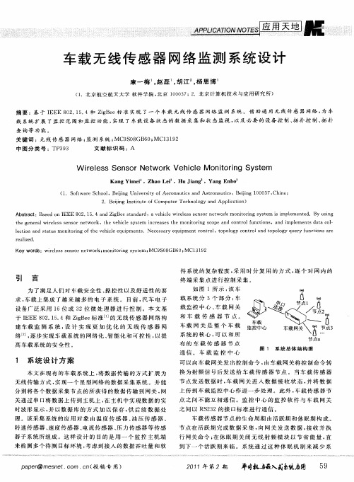
换 为射 频 信 号 后 发 送 给 车 载 传 感 器 节 点 。 当 车 载 传 感 器 节 点 发送 数 据 时 , 载 网 关 进 入 数 据 接 收 状 态 , 将 数 据 车 并
上 传 到 车 载 监 控 中 心 作 进 一 步 处 理 。此 外 , 载 传感 器 节 车
引 言
为 了 满 足 人 们 对 车 载 安 全 性 、 控 性 以及 舒 适 性 的 要 操
终端 采集点进行控制采集 。
如 图 1所 示 , 车 该
求 , 载 上 集 成 了 越 来 越 多 的 电子 系 统 。 目前 , 车 电 子 车 汽
载 系统 分 3个 部 分 : 车
设备广泛采用 1 或 3 6位 2位 微 处 理 器 进 行 控 制 。本 文 基
摘 要 :基 于 I EE 8 2 1 . E 0 . 5 4和 Zg e iB e标 准 实现 了一 个 车 载 无 线 传 感 器 网络 监 测 系统 。 借 助 通 用 无 线 传 感 器 网络 , 车 为 载 系统 扩 展 了监 控 范 围和 监 控 功 能 , 实现 了车 载 设 备 状 态 的数 据 采 集 和 状 态 监 视 , 以及 必要 的设 备 控 制 、 扑 控 制 、 扑 拓 拓 查询等功能 。
载 监 控 中心 、 载 网 关 车 和车 载 传 感 器 节 点。
传感器技术外文文献及中文翻译
传感器技术外文文献及中文翻译引言传感器是现代检测技术的重要组成部分,它能将物理量、化学量等非电信号转换为电信号,从而实现检测和控制。
传感器广泛应用于工业、医疗、军事等领域中,如温度、湿度、气压、光强度等参数检测。
随着科技的发展,传感器不断新型化、微型化和智能化,已经涵盖了人体所有的感官,开启了大规模的物联网与智能化时代。
本文将介绍几篇与传感器技术相关的外文文献,并对其中较为重要的内容进行中文翻译。
外文文献1标题“Flexible Sensors for Wearable Health: Why Materials Matter”作者Sarah O’Brien, Michal P. Mielczarek, and Fergal J. O’Brien文献概述本文主要介绍了柔性传感器在可穿戴健康监测中的应用,以及传感材料的选择对柔性传感器性能的影响。
文章先介绍了柔性传感器的基本工作原理和常见的柔性传感材料,然后重点探讨了传感材料对柔性传感器灵敏度、稳定性、响应速度等性能的影响。
最后,文章提出未来柔性传感器材料需满足的性能要求,并对可能的研究方向和应用进行了展望。
翻译摘要柔性传感器是可穿戴健康监测中重要的成分,通过将身体状态转化为电信号进行检测。
选择合适的传感材料对柔性传感器产品的成本、性能及标准化有着面向未来的影响。
本文对柔性材料的常见种类 (如: 聚合物、金属、碳复合材料等) 进行了介绍,并重点探讨了传感材料选择的影响因素,如对柔性传感器的灵敏度、特异性和响应时间等。
此外,文章还探讨了柔性传感器的性能要求和建议未来的技术方向。
外文文献2标题“Smart sensing system for precision agriculture”作者Olivier Strauss, Lucas van der Meer, and Benoit Figliuzzi文献概述本文主要介绍智能传感系统在精准农业中的应用。
基于无线传感器网的车内环境监测系统研究-电子信息
毕业设计(论文)题目基于无线传感器网的车内环境监测系统研究学生毕业设计(论文)原创性声明本人以信誉声明:所呈交的毕业设计(论文)是在导师的指导下进行的设计(研究)工作及取得的成果,设计(论文)中引用他(她)人的文献、数据、图件、资料均已明确标注出,论文中的结论和结果为本人独立完成,不包含他人成果及为获得重庆工程学院或其它教育机构的学位或证书而使用其材料。
与我一同工作的同志对本设计(研究)所做的任何贡献均已在论文中作了明确的说明并表示了谢意。
毕业设计(论文)作者(签字):年月日摘要近年来,随着社会飞速的发展,汽车作为最亲民的消费产品,深受广大人民的喜爱,而车内空气环境的监测技术及标准化比较匮乏,车内空气质量问题日益显著。
车内污染气体如甲醛、一氧化碳等,对人们身体健康造成诸多伤害,因此对车内环境进行实时监测显得异常重要。
针对上述问题,本课题设计了一款车内空气监测系统,该系统由硬件和软件设计两部分构成,其原理是利用气敏传感器来监测车内一氧化碳、甲醛、酒精等气体浓度。
该监测系统以STC12C单片机为核心,由一氧化碳传感器、甲醛传感器、蓝牙模块、报警电路等模块组成。
系统由传感器模块采集数据,传输到主控制器中,来显示车内环境参数浓度值以及超阈值声光报警。
监测结果表明,本文设计的基于无线传感器网车内环境监测系统研究,实现了车内环境的监测,具有一定的实用价值。
关键词:无线传感器监测单片机系统设计ABSTRACTWith the rapid development of society and the continuous improvement of people's living standards, the original horses, carriages and other means of transportation have developed into the current vehicles, trains and airplanes as the main means of transportation. As a consumer-friendly product, the car has been loved by the people. It has now become a major means of transportation, greatly facilitating people's lives. However, cars also pose a hazard to people's health. Many drivers are driving vehicles. When it is easy to get sleepy, this is partly because of the air quality inside the car and the temperature and humidity of the car's environment. In addition, the materials used in the car structure will be released under certain circumstances. The health of the people inside the car. Therefore, monitoring the internal gas quality of the car is very important.This paper proposes a more effective, timely and low-cost method for on-line real-time monitoring of vehicle gas quality than traditional methods, and designs a gas quality monitoring system based on wireless sensor network. The current air quality detectors in the vehicle were analyzed and studied, and the overall scheme and hardware and software design of the newly developed detectors were carried out. After debugging, the parameter concentration state such as temperature, relative humidity, CO2 and formaldehyde content in the vehicle can be detected, and the air quality information in the vehicle can be displayed in real time by using the LCD, and different thresholds can be set according to different environments. The threshold is audible and visual to alert the hazard. The innovation is: the control of the sensor power supply through the keyboard, to achieve the purpose of reducing power consumption and enhancing flexibility; the wireless detector and the wireless display controller are independent of each other, flexible to place, and convenient to use.This topic is divided into two parts: the hardware design part and the software design part.The hardware part uses the SSC811 gas sensor to measure the carbon dioxide CO2 sensor module board in the air, temperature and humidity, VOCs, air quality, and converts it into a voltage signal, which is converted into a digital signal by the A/D converter and then transmitted to the single-chip system, by the single-chip microcomputer and The corresponding peripheral circuit performs signal processing, and displays air monitoring parameter concentration values and super-threshold sound and light alarms. The program adopts the modular design idea, and the functions of each subroutine are relatively independent, which is convenient for debugging and modification. The hardware circuit canbe roughly divided into single-chip small system circuit, A/D conversion circuit, sound and light alarm circuit, LCD liquid crystal display circuit, button circuit, and the design and principle of each part of the circuit will be introduced in detail in the hardware circuit design part.The measurement results show that the wireless sensor network in-vehicle gas monitoring system designed in this paper can respond well, the measurement accuracy is accurate, and it has high practicability.Keywords: wireless sensor network; measurement;interior air; system design目录摘要 (I)ABSTRACT (II)1 绪论 (1)1.1 课题研究背景及意义 (1)1.2 国内外研究现状 (1)1.3本文主要研究内容 (2)1.4 气体检测方法介绍 (2)1.4.1 电化学传感器检测方法 (2)1.4.2 金属半导体检测方法 (3)1.4.3 红外吸收传感器检测方法 (3)1.5 车内环境监测总体方案设计 (3)1.5.1 车内环境监测研究要求分析 (3)1.5.2 车内环境监测设计方案 (4)1.6 本章小结 (4)2 硬件设计 (5)2.1 传感器的选择 (5)2.1.1 MQ-3酒精传感器电路 (5)2.1.2 MQ-7一氧化碳传感器电路 (6)2.2 A/D转换电路 (6)2.3 STC12C5A60S2单片机系统 (7)2.3.1 STC12C5A60S2单片机片简介 (7)2.3.2 最小系统 (8)2.3.3 STC12C中断技术 (9)2.4 LCD1602液晶显示电路 (10)2.5 报警电路 (12)2.5.1 灯光提示电路 (12)2.5.2 声音报警电路 (13)3 软件设计 (14)3.1 编程语言选择 (14)3.2 软件功能需求 (15)3.3 软件设计 (15)3.3.1 主程序设计 (15)3.3.2 A/D转换程序设计 (16)3.3.3 液晶显示程序设计 (17)3.3.4 声光报警程序设计 (17)4 调试及测试结果 (19)4.1 硬件调试方法 (19)4.2 系统硬件调试 (19)4.3 系统软件调试 (19)4.4 调试 (19)4.4.1 晶振电路和复位电路 (20)4.4.2 蜂鸣器驱动电路和去耦电路 (20)4.4.3 MQ3酒精传感模块和MQ7甲醛传感模块 (21)4.4.4 LCD显示模块和蓝牙模块 (22)4.4.5 单片机接口 (22)4.5 软件实现 (23)4.5.1 延时程序 (23)4.5.2 STC12C5A60S2 ADC程序 (23)5 总结 (25)参考文献 (26)致谢 (27)附录 (28)1 绪论1.1 课题研究背景及意义随着中国汽车工业的蓬勃发展,在不久的将来,中国的汽车保有量将超过美国,真正成为世界上最大的汽车生产国,而中国对汽车污染物的关注还远远落后于发达国家。
- 1、下载文档前请自行甄别文档内容的完整性,平台不提供额外的编辑、内容补充、找答案等附加服务。
- 2、"仅部分预览"的文档,不可在线预览部分如存在完整性等问题,可反馈申请退款(可完整预览的文档不适用该条件!)。
- 3、如文档侵犯您的权益,请联系客服反馈,我们会尽快为您处理(人工客服工作时间:9:00-18:30)。
Wireless sensor network monitoring system designKang yi-mei,Zhao lei,Hu jiang,Yang en-bo(Study on Beijing University of Aeronautics and Astronautics)Summary: A car wireless sensor network monitoring system based on IEEE 802.15.4 and ZigBee standards. With universal wireless sensor networks, expansion of the scope of monitoring and monitoring functions for in-car system, car data acquisition and condition monitoring of equipment status and the necessary equipment control, topology control, topology query functions. Keywords: wireless sensor networks; monitoring systemIntroductionIn order to satisfy the people to car safety, handling and comfort requirements, vehicle integrated with more and more electronic system .At present, car electronic equipment is widely used 16 or 32-bit microprocessor control. Creating in-vehicle monitoring system based on IEEE 802.15.4 and ZigBee standard for wireless sensor networks, designed to achieve a more optimized wireless sensor networks, the progressive realization of the network of automotive systems, intelligent and controllable to provide high-Car System security.System designIn this paper, the existing vehicle system, the data transmission mode is extended to the wireless transmission mode, the realization of a star network data acquisition system. And can place each data acquisition node of the acquired data is transmitted to the gateway, the gateway through the serial port to upload data to the host computer, in the host data real-time waveform display, and method of database to preserve, for the follow-up data processing. The application of system object is composed of a temperature sensor, pressure sensor, speed sensor, speed sensor, a current sensor, pressure sensor, sensor subsystem. The purpose of this design is to use a monitoring host machine end to the detection of multiple target environment, taking into account the access data throughput and software system complexity, using time-division multiplexing way, one by one on the net terminal collecting point of control and data acquisition.As shown in Figure 1, the system is divided into 3 parts: Vehicle Monitoring Center, gateway and mobile sensor node. Gateway is the whole vehicle system core, and all vehicular sensor node communication. Vehicle monitoring center to the gateway sends a control command by the gateway, the control command is converted to an RF signal and sent to the vehicle sensor node. When the vehicle sensor nodes to transmit data, gateway into the data reception state, and upload data to the monitoring center for further processing. In addition, car between sensor nodes cannot communicate with each other. The monitoring center of the monitoring software and gateway in RS232standard interface for communication.Vehicle sensor node life cycle is active and dormant periods. Nodes in the active phase of the completion of data acquisition, data sent to the gateway, receiving andexecuting gateway command; in the dormant period off the wireless RF module in order to save energy, until the next active period. System through this mechanism of dormancy to reduce energy consumption, extend the time span of the system as a whole.The system used PC as the control center, PC machine monitoring software in VB development environment, is a dialog based application software. In order to improve the communication module of the intelligent level, in the design, its function is not limited to the real-time data display, all of the data collection by the monitoring software by sending a request signal to the trigger. Considering the original data for subsequent processing and in-depth analysis of the vehicle system, can accurately judge, software has also added data preservation of the document and data file display function.Generally speaking, the whole network are controlled by the host monitoring software, the working process of every node of the network is the need of human participation.2 hardware system design2.1application chip introductionMC13192with IEEE802.15.4 standard, the operating frequency is2.405~2.480 GHz, data transmission rate of 250kbps, using 0-QPSK debugging mode. This feature-rich two-way 2.4GHz transceiver with a data modem which can be in the ZigBee technology application. It also has an optimized digital core, helps to reduce the MCU processing power, shorten the cycle of execution.The main control MCU choose HCS08series of low power, high performance microprocessor MC9S08GB60. The processor has a 60Application of KB programmable Flash、4 KB RAM,10 ADC,8 channel2 asynchronous serial communication interface ( SCI ),1 synchronous serial interface ( SPI ) and I2C bus module, can fully meet the requirement of vehicle gateway and node processor requirements.2.2 MCl3192and MC9S08GB60hardware connectionMC13192and MC9S08GB60 hardware connection diagram as shown in figure 2. The MC13192control and data transmission on 4 wire serial peripheral interface ( SPI ) is completed, the4interface signals were MOS-I, MISO,, SPICLK. The main control MCU through the control signal exiting sleep mode or hibernation mode, through to reset the transceiver, through the RXTXEN to control the data sending and receiving, or force the transceiver into idle mode. The sensor output analog signal through MCU 8 Channel10 bit ADC conversion input to MCU. MCU via SPI MC13192to read and write operation, and the sensor to collect the signal processed by MC13192launch out. The MC13192 interrupt IRQ interrupt register through the pins and to judge the type of interrupt. MC908GB60 pin to control the MC13192 into a different mode of operation .Control of the sensor signal from the MC13192receiving antenna in, transmitted via SPI to MCU, after MCU judgment after processingthrough the GPIO port is transmitted to the sensor, complete control of the sensor. At the same time, MCU MC13192transceiver control and the MAC layer operation. The 3system software design3.1of overall software designThe software design is the design of the core, the key lies in the overall framework of software and data structure design. An important factor to consider is a efficiency, another is to design the clarity.System software consists of the gateway node and the sensor node is composed of two parts, the two parts are needed to complete the SMAC protocol transplantation, and according to the different needs for the upper communication applications with API interface function. Because the SMAC protocol stack programming model using hierarchical design, only the underlying PHY and MAC program level and related hardware, and network layer and application layer procedures is not affected by hardware effects. SMAC in different hardware platform transplantation only need to modify the PHY and MAC layer, each layer can shield the hardware differences directly run.As shown in Figure 3, the design of the software for system platform layer, protocol layer and application layer 3layer. At the same time, defines 3API interface: system layer interface, protocol layer and application layer interface. System level interface defines a hardware register mapping, so C language to be able to directly access the hardware registers to control hardware. System platform based on real-time operating system μC/II protocol layer, to provide system services Hardware driving module provides the hardware driver, all of the hardware control through the module to provide services. Platform layer protocol layer interface protocol layer to provide services. Protocol layer is based on the IEEE 802.15.4 physical layer and link layer based on the ZigBee network layer protocol. Application layer through the application layer interface to invoke services provided by the protocol layer, network management and data transfer tasks. Application of configuration module can call protocol layer to provide network services, will direct the system configuration and query, it is mainly through the AT commands to achieve, so the module calls the application layer interface and protocol layer interface to provide services.3.2sensor node software designBased on the long-term use of the functional requirements, sensor nodes in the software design is the key to achieve the required functions, and can minimize the energy consumption of the sensor nodes.It was found, ZigBee module and the energy consumption is much larger than the central processor and the energy consumption of sensor module. Therefore, the sensor node design of application software to try to make each module in a dormant state, and minimizing wakes ZigBee module number. Therefore, the sensor nodes, power of each functional module initialization is completed, and joined the network, enter the Sleep state, the central processor cycles to be timed wake-up to send data tothe gateway, and receives the gateway command. Sensor nodes of the workflow are shown in Figure 4.The 3.3 gateway node software designGateway downward management sensor node, to complete and PC monitoring center of interaction, the need for a complicated task management and scheduling, therefore, based on the uC / OS kernel of embedded operating system to manage the gateway, the application task efficiently provide good software support. According to gateway function demand, the μC / OS-II, SMAC protocol organic union, form a network operating environment, the user can conveniently on the basis of its development and application. Based on μC / OS-II extended gateway software platform structure is shown in figure 5. Based on μC / OS-II operating system, were used to build the system task SYS_task ( ), START_task ( SMAC star network task ), gateway and a sensor node interaction task COMM_task ( ), PC monitoring center port monitoring mission ( SER_task ) applications such as a series of tasks, thus realizing the gateway software application function.The 3.4 host monitoring software designThis system is the ultimate goal of the collected vehicle sensor data is transmitted in real-time to the host, and the host of display and preservation. Display is designed to get on-board sensor node monitoring environment of the initial situation, preservation is designed as an in-depth analysis of the data samples. In addition, the system as a whole the main prosecution and the data acquisition request initiator, need to be able to send the data request signal in accordance with the requirements of. According to the above requirements, VB environment in the development of a dialog based application. This application includes a 4 module:①data waveform display module. The role of the module is a form of waveform data of the node to be displayed in real-time, it is the use of MS Chart and Timer control.②topology display module. When the user wants to know the wireless sensor network topology construction situation, you can view the topological information, understanding of network nodes join and loss.The historical data display module. In vehicle network system to a certain period of the past, may need a certain period of time the original data for subsequent processing and in-depth analysis, so that the vehicle system of accurate judgement. With the aid of historical data display module, the control center from the gateway of the data obtained, according to the different attributes of the nodes, address and time are saved to the database of the corresponding field, and may be will displayed by waveform of historical data, for the user analysis.The controlling module :In vehicle during system operation may be concerned about a vehicle sensor value node, or to a sensor threshold settings, for monitoring environmental exceptions can be promptly reported to the system. These are available through the control module of the system are corresponding to the set, the control module can also be on the system in which one does not need to delete the node.In short, through the host monitoring software users can visually and many aspects ofgeneral wireless sensor network systems to understand and use.4 test and verification4.1 testingTesting equipment:4 MCl3192ZigBee chip node,1as a gateway node, the remaining 3as sensor nodes.Test method: the gateway node power,4 LED and light, scanning channel if the search to the idle channel, the LED goes out and join the free channel for. The sensor node power,4 LED scanning in the channel at the same time, polling light. LED1 flashes once when the sensor nodes receive the allocation address of the gateway node, So far, networking process and address binding process is complete.4.2 Zigbee RF communication testTesting equipment: ZigBee node 4, a computer terminal stationTest method: according to the ZigBee transmission frame format, the actual transmission total bytes for ( n 6), namely ( n 6) bytes for a data packet. According to the set parameters of the software, such as packet loss is the loss number plus 1. If the received data packet, receives the data packet number plus 1, and then sends the data were compared with data, if the data is correct, the number of packets plus 1, and error packets number plus 1. The last statistic results, can know the data packet loss and packet error rate. The 4 node to form a ZigBee network,1 of them as the gateway, the remaining 3 nodes for sensor node. Write a program to set:3nodes and gateway communications, computer terminal and the gateway is connected through RS232, terminal equipment software records from the 3node to receive data, nodes work at 2.4 GHz frequencies, transmission of a byte of data, circular send 100 times. To obtain the final3 node test average as a result of the data analysis. Star network radio frequency communication BER test results as shown in table 1.Experimental analysis of: in a star network for data transmission, the test results significantly worse on a single point to single point transmission mode. This is mainly because, in the transmission process node must exist between the frequency interference and other interference.4.3power testSystem status and hibernation, respectively, using a multimeter to test the gateway node and the power consumption of sensor nodes, the test results listed in Table 2.ConclusionThis paper analyzes the IEEE 802.15.4 and ZigBee protocol, combined with the general development principles of communication systems and embedded systems, IEEE802.15.4 protocol on the μC / OS-II operating system, select the appropriate hardware and software platform, focusing on software support for the platform, the software design of the overall structure of the communication protocol stack, andultimately to achieve a compliant with the ZigBee specification car star wireless data acquisition network. The system has the following advantages:①system easy to install. Wireless interconnection makes the equipment installation location is flexible to meet the requirements of the automation system is installed. It is simply that the power can take equipment. The network system can automatically complete the network configuration.②scalability. Equipment within the coverage of the vehicle gateway, turn on the device, the node will automatically join the network.③network self-healing ability. If the network is a device fails, the vehicle gateway can automatically monitor, issue the command the device reset and re-network.车载无线传感器网络监测系统设计康一梅,赵磊,胡江,杨恩博(就读于北京航天航空大学)摘要:基于IEEE 802.15.4和ZigBee标准实现了一个车载无线传感器网络监测系统。