DHDAS2013版使用手册V1.3
数字监控系统DSS管理员端使用手册
目录目录1 概述...........................................................................................................................................1-11.1 术语..............................................................................................................................................................1-21.2 简介..............................................................................................................................................................1-22 系统登陆.......................................................................................................................................2-12.1 登陆准备......................................................................................................................................................2-22.2 系统登陆......................................................................................................................................................2-23 页面说明.......................................................................................................................................3-14 系统配置.......................................................................................................................................4-14.1 简介..............................................................................................................................................................4-24.2 业务设置......................................................................................................................................................4-44.2.1 组织结构管理.....................................................................................................................................4-44.2.2 设备管理............................................................................................................................................4-54.2.3 权限组管理........................................................................................................................................4-74.2.4 用户管理..........................................................................................................................................4-134.2.5 存储计划管理...................................................................................................................................4-164.2.6 报警联动管理...................................................................................................................................4-194.3 系统设置....................................................................................................................................................4-224.3.1 常规设置..........................................................................................................................................4-224.3.2 服务设置..........................................................................................................................................4-234.4 运行状态....................................................................................................................................................4-274.4.1 系统日志..........................................................................................................................................4-274.4.2 设备状态列表...................................................................................................................................4-274.4.3 用户状态列表...................................................................................................................................4-284.5 注销系统....................................................................................................................................................4-29插图目录图1-1 数字监控系统DSS组网结构示意图...................................................................................................1-3图2-1 系统登陆界面示意图.............................................................................................................................2-2图2-2 视频监视界面示意图.............................................................................................................................2-3图2-3 控件下载提示框示意图.........................................................................................................................2-3图3-1 视频监视界面介绍图.............................................................................................................................3-1图3-2 菜单项伸缩示意图.................................................................................................................................3-1图4-1 系统配置流程图:.................................................................................................................................4-3图4-2 组织结构管理界面示意图.....................................................................................................................4-4图4-3 组织结构编辑界面示意图.....................................................................................................................4-4图4-4 组织结构添加界面示意图.....................................................................................................................4-5图4-5 组织结构删除节点提示框示意图.........................................................................................................4-5图4-6 设备管理界面示意图.............................................................................................................................4-6图4-7 添加设备配置界面示意图.....................................................................................................................4-6图4-8 权限组管理界面示意图.........................................................................................................................4-8图4-9 添加单位管理组界面示意图.................................................................................................................4-8图4-10 编辑单位管理组界面示意图...............................................................................................................4-9图4-11 删除单位管理组提示框示意图...........................................................................................................4-9图4-12 添加单位操作组界面示意图.............................................................................................................4-10图4-13 设置单位操作组界面示意图.............................................................................................................4-11图4-14 设备对应IP地址显示示意图...........................................................................................................4-11图4-15 编辑单位操作组界面示意图.............................................................................................................4-12图4-16 修改设备权限或添加未选设备界面示意图.....................................................................................4-12图4-17 删除单位操作组提示框示意图.........................................................................................................4-13图4-18 用户管理界面示意图.........................................................................................................................4-13图4-19 添加管理员界面示意图.....................................................................................................................4-14图4-20 修改管理员界面示意图.....................................................................................................................4-14图4-21 删除用户组提示框示意图.................................................................................................................4-15图4-22 添加操作员界面示意图.....................................................................................................................4-15图4-23 修改操作员界面示意图.....................................................................................................................4-16图4-24 删除用户组提示框示意图.................................................................................................................4-16图4-25 存储计划界面示意图.........................................................................................................................4-17图4-26 存储计划设置界面示意图.................................................................................................................4-17图4-27 修改周期循环存储计划界面示意图.................................................................................................4-18图4-28 存储计划管理编辑界面示意图.........................................................................................................4-18图4-29 时间重叠提示框示意图.....................................................................................................................4-19图4-30 报警联动管理界面示意图.................................................................................................................4-19图4-31 添加报警联动策略界面示意图.........................................................................................................4-20图4-32 报警联动策略编辑界面示意图.........................................................................................................4-21图4-33 删除报警联动策略提示框示意图.....................................................................................................4-21图4-34 常规设置模块界面示意图.................................................................................................................4-22图4-35 设备编号设置界面示意图.................................................................................................................4-23图4-36 服务设置模块界面示意图.................................................................................................................4-23图4-37 添加服务设置模块界面示意图.........................................................................................................4-24图4-38 服务设备显示界面示意图.................................................................................................................4-24图4-39 IP地址格式填写错误提示框示意图.................................................................................................4-25图4-40 服务器详细信息编辑界面示意图.....................................................................................................4-26图4-41 删除服务信息提示框示意图.............................................................................................................4-26图4-42 系统日志界面示意图.........................................................................................................................4-27图4-43 设备状态列表界面示意图.................................................................................................................4-28图4-44 用户状态列表界面示意图.................................................................................................................4-28图4-45 退出系统提示框示意图.....................................................................................................................4-29表格目录表格目录表1-1 相关术语介绍表....................................................................................................................................1-21 概述关于本章本章描述内容如下表所示。
DS-1T13xA-B探测器说明书
杭州海康威视系统技术股份有限公司| 版权所有(C) 7
六、接线示例
接线示例一:
DS-1T133A-B 三光束主动红外探测器.用户手册
12VDC 报警输入
控制主机
接线示例二:
Ch1
12VDC
报警图输示入
控制主机
Ch1
发射器
接收器
Ch3 Ch3
1 组安装:发射器与接收器电源并接在一起, 使用控制主机 12VDC 供电,报警输出端使 用常闭,如上图:
(1)调整射束频率拨码开关,必需使发射器 与接收器的频率保持一致。如发射器频 率为 CH1,接收器的频率也必需是 CH1。
(2)调整上下角调整螺钉及水平内托架,在 发射器的瞄准镜内,看到接收器,并将 其定位于视线中心。
(3)调整上下角调整螺钉及水平内托架,在 接收器的瞄准镜内,看到发射器,并将 其定位于视线中心。此时数码管读数为 0 到 9 之间的变化。0 表示无信号,此时 处于报警状态,继电器报警输出,报警 指示灯点亮。光轴校正时,数码管的读 数应为 9。
接线示例三:
发射器
接收器
2 组堆叠安装:发射器与接收器电源并接在
一起,使用控制主机 12VDC 供电,报警输 出串接安装:发射器与接收器电源并接在一起,使用控制主机 12VDC 供电.报 警输出端 NC 串接,如下图:
12VDC
图示
报警输入
控制主机
发射器
接收器
接收器
2、常规安装
◆探测距离
型号 DS-1T133A-B DS-1T136A-B DS-1T137A-B DS-1T138A-B DS-1T139A-B
⑤ 需避免空中架线
警戒距离 50m 100m 150m 200m 250m
宝利通信息发布系统dss系统操作手册

睿景系统管理软件系统操作手册南京南方电讯有限公司1引言1.1编写目的本文通过详细描述睿景系统管理软件系统的整体功能、操作流程和操作步骤说明,为操作人员,维护人员和最终用户提供基本的使用说明。
1.2预期的读者和阅读建议2系统综述2.1运行环境表2 运行环境2.2用户类及其要求表3 用户类及其要求3操作说明本系统主要分为五大块:系统管理、终端管理、节目管理、会议指引、视频直播。
各模块具体功能及详细操作步骤如下:3.0 系统概述系统登录页面登录后的整体结构:3.1系统管理模块系统管理模块用来处理睿景系统管理软件系统的系统参数、登录用户权限控制等与整体运行相关的功能. 具体包括部门管理、终端群组管理、用户管理、ftp配置和系统操作日志系统安装完成后需要先完善部门、群组,添加用户,配置ftp信息之后才能正常使用。
3.1.1部门管理部门主要用于来标记系统登录用户的归属。
在系统中不作为进行权限控制的依据。
整体结构:添加部门:选择一个部门作为上级部门,点击“添加”按钮,输入部门名称和部门描述,点击“确定”按钮,新添加的部门就会作为选中部门的子部门添加到系统中。
(如果不选择部门,默认为选中根目录部门)修改部门:删除部门:如果选中的部门内有员工,则不能直接删除。
查看部门内员工:3.1.2终端群组终端群组用于标记接入服务器的终端的群组信息。
在终端群组模块中可以对群组进行添加、修改、删除,查看群组中的终端信息等操作。
整体结构添加群组选择一个终端群组作为上级群组,点击“添加”按钮,输入群组名称和群组描述,点击“确定”按钮,新添加的群组就会作为选中群组的子群组添加到系统中。
(如果不选择群组,默认为选中根目录群组)修改群组。
如果没有选中群组,则默认选中根目录。
删除群组如果群组中有终端,则不能直接删除群组。
查看群组中的终端3.1.3用户管理用户管理用于新增、修改系统登录用户,管理用户权限等。
整体结构添加用户:修改用户:删除用户:3.1.4ftp配置睿景系统管理软件系统的ftp服务器用于保存节目、模板等资源文件。
大华DSS系列客户端操作手册精选V

DSS7000系列客户端操作手册V1.2.0浙江大华科技有限公司前言概述本文档详细描述了DSS7000系列客户端的安装、配置和使用。
符号约定符号说明表示有高度潜在危险,如果不能避免,会导致人员伤亡或严重伤害。
表示有中度或低度潜在危险,如果不能避免,可能导致人员轻微或中等伤害。
表示有潜在风险,如果忽视这些文本,可能导致设备损坏、数据丢失、设备性能降低或不可预知的结果。
表示静电敏感的设备。
防静电表示高压危险。
电击防护表示强激光辐射。
激光辐射表示能帮助您解决某个问题或节省您的时间。
表示是正文的附加信息,是对正文的强调和补充。
目录前言错误!未指定书签。
目录错误!未指定书签。
1概述错误!未指定书签。
1.1产品简介错误!未指定书签。
1.2配置要求错误!未指定书签。
2安装与卸载错误!未指定书签。
2.1安装错误!未指定书签。
2.2卸载错误!未指定书签。
3登录C/S客户端错误!未指定书签。
4配置错误!未指定书签。
4.1本地配置错误!未指定书签。
4.2配置报警预案错误!未指定书签。
4.3配置轮巡任务错误!未指定书签。
5基本操作错误!未指定书签。
5.1实时预览错误!未指定书签。
5.1.1预览............................................................................................................. 错误!未指定书签。
5.1.2录像............................................................................................................. 错误!未指定书签。
5.1.3抓图............................................................................................................. 错误!未指定书签。
汉尚存储转发管理服务器软件用户手册
目录第一章系统概述 (3)第二章使用说明 (3)1登录 (3)2通道列表 (4)3集中存储控制 (5)4集中存储查询 (6)5录像完整性 (6)6补录列表 (8)7集中存储配置 (8)8任务列表 (9)9日志列表 (11)10磁盘信息 (11)11修改密码 (12)12LDAP配置 (13)第一章系统概述欢迎使用汉尚网络监控平台存储转发管理服务器软件!汉尚存储转发管理服务器软件是用于SIP应用平台中,对所属通道进行录像集中管理的平台。
平台主要作用有:对所属通道,分别进行录像存储控制、建立录像计划任务、录像集中查询和下载等。
本手册可能包含技术上不准确的地方。
我们随时会改进或更新本手册中描述的产品或程序。
第二章使用说明1登录在IE地址栏输入:http://服务器IP/jzcc,回车后,出现用户登录界面。
输入用户名和密码(默认为admin/123456),点击登录,进入系统界面。
如图:注意:在第一次使用此系统时,需要安装控件。
控件可以在登录页面,点击“控件下载”进行下载。
登录成功后进入系统首页(默认是通道列表页面):2通道列表在左侧列表中选择“通道列表”选项进入通道列表界面。
此页面显示平台所有可管理通道列表信息。
如图:在搜索框输入视频源名称包含的关键字,点击“搜索”按键即可搜索视频源。
如在搜索框中输入名称为“cha02”的视频源,点击“搜索”后,出现如下图所示页面:点击某条记录右侧的“开始”即可对此通道进行录像(可在集中存储控制中看到已开始的录像)。
“开始”旁边的蓝色盾牌按钮可以设置和取消保护状态。
3集中存储控制在左侧列表中选择“集中存储控制”选项进入集中存储控制界面。
这里显示的是所有正在进行录像的通道列表详细信息,可以在此处单独针对某个通道任务进行停止录像的操作。
如图:搜索:输入关键词,点击“搜索”按键即可搜索指定列表(如果选定了右上角的“自动更新”,无需点击“搜索”就可以自动搜索)。
以在搜索框中输入“cha07”为例,点击“搜索”,如图:停止:点击“停止”按键即可停止此通道的录像任务。
数字监控系统DSS安装手册
数字监控系统DSS安装手册1.最低系统配置要求服务器:z CPU 酷睿2双核2.2z内存 1Gz硬盘 5G剩余空间(不带存储)z Microsoft Windows 2003 Serverz Internet Explorer 6.0z100M以太网卡客户端:z CPU P4 2.4Gz内存 512Mz硬盘 100M剩余空间z DirectX 8z1024*768分辨率显示器及显卡z Internet Explorer 6.02.安装说明服务器安装1)运行“DSSServer_V1.0_build_20090116_CHS.exe”进行数字监控系统程序的安装,首先进入安装界面2)单击按键进入选择安装路径界面在此步骤可点击按键更改默认安装路径(默认为“C:\Program Files\数字监控系统”)。
3)确认安装路径后,单击按键继续安装操作4)单击按键继续安装5)安装完成后,自动进入配置向导界面此步骤中可选择按键直接完成安装,但建议按照下述介绍逐步进行配置后再完成安装。
配置向导介绍表配置项说明开机自动运行选择此项则后续服务器开机时程序将自动运行 服务器地址 服务器使用的本机IP ,如192.168.0.1普通设置外网映射地址服务器在内网,并且使用了路由器DMZ 映射供外网用户使用时,需要设置外网的DMZ 映射IPCMS 设置 CMS 监听端口 CMS 工作端口,默认9000 DMS 设置 DMS 监听端口 DMS 工作端口,默认9200MTS 的RTSP 端口 MTS 工作的RTSP 端口,默认9100 MTS 的RTP 端口范围MTS 的RTP 端口,默认10000到30000,端口数必须大于等于2000MTS 设置UDP 包长UDP 数据分组长度,默认1400BYTE ,局域网下推荐1400,窄带带宽下需要设置小些的数值,一般设置为500SS 的RTSP 端口 SS 的RTSP 端口,默认9320 SS 的RTP 起始端口范围默认30000,必须大于MTS 的RTP 端口 RTP 传输协议UDP/TCP 可选。
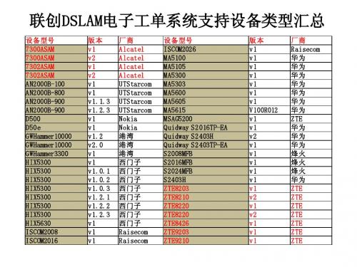
联创DSLAM网管电子工单系统操作说明
如更新设备较多,可选择更新所有设备后台配置
如果一次开通设备数量较少,尽量不要使用更新所有设备后台配置,短时间内会占用一 定系统资源造成不便
更新成功,开通完毕
节点开通电子工单步骤
资源管理中修改 节点信息
业务开通中开通 该节点电子工单
更新后台配置
ADSL工单管理主要使用模块 • 错单处理:可以查看所有失败工单并重新激活或人工处理。 • 工单视图:主要使用的工单维护界面,可以看到所有的工 单,包括执行成功、执行失败、手工标成功、手工标失败、 激活中等。 • 工单查询:可以根据指定条件查询某个工单。
• 手工回单:电子工单由于某些原因始终无法自动处理时, 就需要人工处理,处理后选择手工回单有两种方式,标成 功和标失败。标成功后电子工单会认为无需人工处理,工 单会直接进入下一环节,比如宽带装机;标失败后电子工 单会认为需要人工处理,工单会被返送97系统DSLAM网管部分可以指定过滤的条件,如时间、地区、成功失败等等,同时工单状态用不 同颜色区分
• 红色代表未处理的失败工单。此类工单由于某些原因电子 工单没有处理成功,需要人工操作选择重新激活、手工回 单标成功还是手工回单标失败,日常维护主要查看红色工 单。 • 绿色代表已处理并手工回单的工单。此类失败工单已被人 工标成功或标失败,如果标成功则无需再看,如果标失败 则需到97中DSLAM网管工位中提单。 • 白色代表电子工单系统执行成功的工单,一般无需查看。
联创DSLAM电子工单系统(城域网管系统)登录界面
系统登录网址 http://60.215.133.8:8080/ldims/login.jsp
登陆后系统主界面
日常工单维护主要使用的主菜单有资源管理和业务开通两项
资源管理界面
资源管理主要相关DSLAM节点信息的维护,包括添加、删除、修改,而资源管理里面主 要用到设备资源列表和添加设备资源两个界面
DSS系统使用手册(中文版)最详细

数字媒体发布系统使用手册目录DSS系统名词解释...................................................................................................................................... - 3 -一.软件的安装......................................................................................................................................... - 5 -二.视频播出功能软件和插件的安装....................................................................................................... - 8 -2.1M ICROSOFT M EDIA P LAYER 10插件的安装(必须W INDOW XP及以上版本) (8)2.2M ICROSOFT P OWER P OINT VIEWER 97插件的安装 (9)2.3A DOBE FLASH PLAYER 9A CTIVE X插件的安装 (10)2.4 FFDSHOW插件的安装 (10)2.6Q UICK T IME A LTERNATIVE插件的安装 (11)2.7R EAL A LTERNATIVE插件的安装 (11)三.MICROSOFT补丁包的安装 ............................................................................................................... - 12 -3.1M ICROSOFT D IRECT X插件的安装: (12)3.2M F RAMEWORK 1.1安装步骤 (13)四.DSS 2.5版本系统软件的设置 ........................................................................................................... - 13 -4.1DSS2.5版本系统软件介绍 (13)4.1.1 DSS Editor的介绍.................................................................................................................... - 13 -4.1.2 DSS Server Daemon的介绍 ...................................................................................................... - 14 -4.1.3 DSS Network Manager的介绍 .................................................................................................. - 14 -4.2DSS系统软件的设置 (14)4.2.1设置DSS Server Daemon........................................................................................................... - 14 -4.2.2设置DSS Editor......................................................................................................................... - 15 -4.2.3设置DSS Network Manager ....................................................................................................... - 18 -五.应用软件使用说明 ........................................................................................................................... - 20 -5.1DSS E DITOR的使用说明 (20)5.1.1 文本制作单元............................................................................................................................. - 22 -5.1.2 RSS导入单元.............................................................................................................................. - 25 -5.1.3 Alpha和Alpha序列导入单元(透明图片及透明序列) ...................................................... - 26 -5.1.4 网页导入单元............................................................................................................................. - 27 -5.1.5 视频,音频导入单元................................................................................................................... - 27 -5.1.6 图片导入单元............................................................................................................................. - 28 -5.1.7 数据导入单元............................................................................................................................. - 29 -5.1.8 流媒体导入单元......................................................................................................................... - 30 -5.1.9 复合区域导入单元..................................................................................................................... - 31 -5.1.10 FTP更新目录导入单元............................................................................................................ - 32 -5.1.11设置播放顺序............................................................................................................................ - 33 -5.1.14添加页面序列............................................................................................................................ - 34 -5.1.15 发布项目................................................................................................................................... - 35 -5.2DSS N ETWORK M ANAGER的使用说明 (36)5.2.1界面说明...................................................................................................................................... - 36 -5.2.2针对整个网络的操作.................................................................................................................. - 37 -5.2.3编辑播放器/播放器组................................................................................................................ - 38 -5.2.4查看和编辑播放器及播放器组的信息 ...................................................................................... - 39 -5.2.5右侧状态信息界面的说明及操作 .............................................................................................. - 40 -5.2.6针对播放器组的操作(图5-52) ............................................................................................. - 43 -5.2.7课表管理的使用.......................................................................................................................... - 44 -5.2.8服务信息的查看.......................................................................................................................... - 48 -5.2.9节目管理的使用.......................................................................................................................... - 49 -5.2.10 DataFlow功能的使用.............................................................................................................. - 50 -六.播放器的使用(WS-20HD) .................................................................................................................. - 51 -6.1播放器配置 (51)6.2注意事项 (55)6.3故障处理 (56)七.软件注册........................................................................................................................................... - 57 -7.1DSS E DITOR(编辑制作端)注册流程 (57)7.2DSS N ETWORK M ANGER注册流程 (58)7.3DSS S ERVER D AEMON注册过程 (60)7.4DSS P LAYER注册过程 (60)7.4.1单个DSS Player注册(一) .................................................................................................... - 60 -7.4.2单个DSS Player注册(二) .................................................................................................... - 62 -7.4.3多个DSS player和DSS Server Daemon批量注册 ................................................................ - 63 -八.应用实例- 编辑发布和播放一个节目.............................................................................................. - 64 -8.1启动Q OVISION S ERVER D AEMON (64)8.2制作节目 (65)8.3管理和指派节目 (73)九.扩展功能介绍 ................................................................................................................................... - 76 -9.1D ATAFLOW功能说明 (76)9.2连接LED显示屏 (79)9.3连接医院/银行排队叫号系统 (80)十.DSS 售后服务......................................................................................................... 错误!未定义书签。
DHDAS2013版使用手册V1.3

DHDAS软件使用说明书V1.3江苏东华测试技术股份有限公司DHDAS使用手册V1.2Dong-Hua TestReal Time Data Measurement and AnalysisSoftware SystemUser’s ManualV1.2目录一、软件安装 (1)1.1安装前的准备 (1)1.2安装软件 (2)1.3硬件配置要求 (3)1.4系统要求 (3)二、接口设置 (4)2.11394接口 (4)2.2NET接口 (7)2.3PCI接口 (9)2.4Z IG B EE接口 (11)2.5USB接口 (12)三、快速入门 (14)3.1工程管理 (14)3.2设置测量通道 (14)3.3设置存储规则 (15)3.4实时信号处理 (15)3.5实时测量 (16)3.6数据显示 (17)3.6.1 记录仪 (18)3.6.2 2D图谱 (18)3.6.3 FFT视图 (18)3.7数据回放 (19)3.8分析报告 (19)四、软件界面介绍 (20)4.1工程管理界面 (20)4.2测量模式界面介绍 (20)4.2.1 参数管理界面 (20)4.2.2 参数设置界面 (21)4.2.3 信号处理界面 (22)4.2.4 测量界面 (22)4.2.5 图形区设计 (23)4.2.5.2 2D图谱 (24)4.2.5.3 FFT视图 (25)4.2.5.4 XY记录仪 (25)4.2.5.5 倍频程 (26)4.2.5.6 数字表 (26)4.2.5.7 棒图 (26)4.2.5.8 3D图谱 (27)4.2.5.9 表格 (27)4.2.5.10 动平衡 (28)4.2.5.11 极坐标 (28)4.2.5.12 视频 (29)4.2.5.13 冲击波型检测 (29)4.2.5.14 模型视图 (29)4.2.5.15 阻尼比计算 (30)4.2.5.16 时域阻尼比计算 (30)4.2.5.17 冲击系数 (31)4.2.5.18 桩基检测 (31)4.2.5.19 材料特性计算 (32)4.2.5.20 标定视图 (32)4.3分析模式界面介绍 (33)4.3.1 通道界面 (33)4.3.2 事件界面 (33)4.3.3 信号处理界面(分析模式) (34)4.3.4 分析界面 (34)4.2.5 输出 (35)4.2.6 打印 (35)五、工程管理 (36)5.1新建工程文件 (36)5.2打开工程文件 (36)六、测量模式 (38)6.1参数管理 (38)6.2参数设置 (38)6.2.1 模拟通道设置 (38)6.2.1.1 设置采样频率 (39)6.2.1.2 打开/关闭通道 (39)6.2.1.3 通道分组 (40)6.2.1.4 平衡清零 (40)6.2.1.7 设置通道参数 (41)6.2.1.8 通道设定窗口 (43)6.2.2 信号源通道设置 (47)6.2.2.1 正弦定频 (47)6.2.2.2 定频三角波 (48)6.2.2.3 正弦扫频 (48)6.2.2.4 半正弦 (49)6.1.2.5 猝发随机 (49)6.1.2.6 方波 (50)6.1.2.7 随机 (50)6.2.3 转速通道 (51)6.2.4 计数器通道 (52)6.2.5GPS通道 (54)6.2.6CAN通道 (55)6.2.7视频通道 (57)6.3存储规则设置 (58)6.3.1 数据命名 (58)6.3.2 存储方式 (59)6.4信号处理 (61)6.4.1 新建/删除算法 (61)6.4.2 算法间的连线 (61)6.4.3 频谱分析 (63)6.4.4 幅值分析 (64)6.4.5 倍频程分析 (64)6.4.6 虚拟通道 (65)6.4.7 滤波器 (66)6.4.8 积分微分 (67)6.4.9 统计信息 (68)6.4.10 应变花计算 (69)6.10.1 两片直角形 (69)6.10.2 三片直角形 (70)6.10.3 等腰三角形 (70)6.10.4 伞形 (71)6.10.5 扇形 (71)6.4.11 相关分析 (72)6.4.12 扫频分析 (72)6.4.15 扭矩测量 (74)6.4.16 轴功率测量 (75)6.4.17 频响分析 (76)6.4.17.1 连续 (76)6.4.17.2 触发 (76)6.4.17.3 新建测点 (77)6.4.18 索力测试 (77)6.4.19 阶次分析 (78)6.4.20 现场动平衡 (79)6.5标定 (82)6.5.1 界面参数介绍 (82)6.5.2 操作步骤 (84)6.6测量 (85)6.6.1 启动、停止存储 (85)6.6.2 布局设计 (85)6.6.3 选择信号 (86)6.6.4 视图操作 (86)6.6.4.1 曲线显示 (86)6.6.4.2 光标读数 (88)6.6.5 统计信息 (91)七、分析模式 (92)7.1通道参数修改 (92)7.2查看存储事件 (92)7.3事后信号处理 (93)7.3.1 修改算法参数 (93)7.3.2 材料特性计算 (93)7.3.3 雨流分析 (93)7.4事后分析 (94)7.4.1 更改数据范围 (95)7.4.2 激活测试 (95)7.5数据输出 (96)7.5.1 快速输出 (96)7.5.2 输出管理 (96)7.5.3 输出excel、txt、Matlab、UFF (97)7.5.4 输出word (97)7.5.6 输出报告 (98)7.5.6.1 PCB板测试报告输出 (98)7.6打印 (102)八、试验模态分析 (103)8.1模态简介 (103)8.2模型 (104)8.2.1 新建/删除模型文件 (104)8.2.2 导入模型 (104)8.2.3 自动建模 (105)8.2.4 手动建模 (109)8.2.4.1 添加子结构 (109)8.2.4.2 添加点 (110)8.2.4.3 添加线 (111)8.2.4.4 添加面 (112)8.2.4.5 撤销/恢复 (113)8.2.4.6 选择对象 (113)8.2.4.7 复制对象 (114)8.2.4.8 镜像对象 (114)8.2.4.9 拉伸对象 (115)8.2.4.10 旋转对象 (115)8.2.4.11 扩展对象 (116)8.2.4.12 分割线段 (116)8.2.5 编辑测点号 (117)8.3数据管理 (118)8.3.1 采集数据 (118)8.3.2 测力法数据 (119)8.3.3 不测力法数据 (120)8.4参数识别 (121)8.4.1 测力法 (121)8.4.1.1 Polylscf (121)8.4.1.2 导纳圆 (124)8.4.1.3 峰值拾取 (124)8.4.1.4 复指数拟合 (125)8.4.1.5 整体多项式拟合法 (126)8.4.2不测力法 (127)8.5振型 (130)8.5.3 改变动画速度 (131)8.5.4 改变动画幅度 (131)8.5.5 按帧显示 (131)8.5.6 动静对比 (131)8.5.7 矢量图显示 (131)8.5.8 彩色云图显示 (131)8.5.9 输出A VI (132)8.6模态验证 (132)8.6.1 MAC (132)8.6.2 MSF (132)8.6.3 MOV (132)九、声学分析 (133)9.1声压 (133)9.1.1 参数设置 (133)9.1.2 声压测量及结果显示 (134)9.2声强 (134)9.2.1 参数设置 (134)9.2.2 声强测量及结果显示 (135)9.3声阵列 (136)9.3.1 参数设置 (136)9.3.2 结果显示 (137)9.4声功率 (138)9.4.1 参数设置 (138)9.4.2 结果显示 (139)十、其他功能 (140)10.1数据回收管理 (140)10.2风格设置 (140)10.3导入DHDAS2003软件数据 (141)10.4应力云图 (143)10.5多客户端设置 (145)十一、附录 (146)附录一霍布金森杆实验模块 (146)附录二版本说明 (152)重要说明:本使用手册中所写均为完全版软件的功能介绍及描述,具体开放的功能以实际购买、发货为准。
GRED HD-2013说明书
1.说明1.1目的GRED HD是由IDS公司开发的适用于Window 7 操作平台的处理软件,主要用于对IDS 地质雷达系统所有型号天线采集的雷达数据进行显示、处理和分析的软件。
特别是可以通过所有能用的3D算法对雷达数据进行处理、分析,并以二维模式和三维模式显示。
我们编写这个手册的目的在于给客户介绍地质雷达数据一般情况下的处理步骤:本手册会让你一步步了解从用软件读取原始数据开始到最后将你的结果导入到Auto CAD软件中三维显示的过程。
1.2缩写和定义说明1.2.1缩写GRED:地质雷达数据解释(Georadar Data Elaboration)HD:高密度(High Density)1.2.2定义下面是IDS地质雷达和GRED HD软件共有的一些名词解释:ŸAntenna:频率范围为25MHz到2GHz的电磁波探头。
ŸDETECTOR DUO:包含一个双频(250-700MHz)天线探头主要用于市政管线现场勘测用的雷达系统。
ŸHi-MOD:主要用于市政和考古领域测绘的包含#1 、#2、#3或#4双频(200-600MHz和/或400-900MHz)天线探头的雷达系统。
ŸALADDIN BIPOLAR:用于市政工程领域包含2GHz垂直交叉极化双通道的雷达系统。
ŸHI-PAVE:由喇叭口天线模块(1GHz 和/或2GHz)加上一个中频天线(900MHz 和/或600MHz)或一个Hi-Mod天线(200-600或400-900MHz)组成的雷达系统。
主要用于交通工程检测领域。
ŸHI-BRIGHT:由16x2000MHz天线组成的雷达系统,用于市政工程检测领域,特别是桥梁和桥面板检测。
ŸSTREAM-X:由16x200MH(或16x600MH)天线组成,通过车辆牵引对大型考古场地进行检测的雷达系统。
也能用于管线测绘领域。
ŸSTREAM-EM:由2x16x200MH和4个Hi-Mod天线组成,通过车辆牵引对大型市政场地进行检测的雷达系统。
DSS软件操作指南
DSS软件操作指南附:设备配置及相关配置手册 DSS服务器推荐配置中心管理服务器Dell PowerEdge 2950 IIIDell PowerEdge 2950 III是一款基于英特尔核心双插槽2U机架式服务器,它能够提供内部扩展能力与机架密度的最佳组合。
基本规格设备类型主板芯片组软盘驱动器光盘驱动器 2U机架式服务器英特尔5000X,1066 MHz和1333 MHz前端总线(FSB) 外置USB软驱可选,CD-ROM,DVD-ROM3或CD-RW/DVD-ROM组合光驱主板扩展插槽(个) 3 后部:4个USB 2.0端口,1个串行接口,1个视频接口,1个用于DRAC 5/i的RJ45接口前部:2个USB 2.0端口、1个视频端口内置USB端口 Microsoft? Windows? Server 2003 R2 处理器端口操作系统处理器配置内存配置2颗主频为3.0GHz的英特尔至强5300系列四核 2个2GB DIMM,总计达到4GB RAM 存储硬盘类型热插拔硬盘 SCSI控制器外部储存 3.5英寸硬盘选项:最多4个SAS(7.2K/10K/15K)或SATA (7200)硬盘支持 4端口SAS控制器,含ARM966处理器。
支持网络网卡类型/数量 IIntel PRO/1000VT 四端口 GbE 电气性能电源类型电源数量额定电压(V)额定功率(W)热插拔冗余电源 1 110/220 750 环境参数工作温度(℃)工作湿度工作高度(米)存储温度(℃)存储湿度存储高度(米)10 - 35 20%至80% (无冷凝) 3048 -40 - 65 5% 至 95% (无冷凝) 10600 数字监控系统DSS2.0分布式服务安装说明1. 安装说明服务器安装1)运行“DSSServer_Distribute_V2.00.1_build_20091109_CHS.exe”进行数字监控系统分布式程序的安装,首先进入安装界面1/ 22)单击按键进入选择安装路径界面在此步骤可点击Files\\DSS”)。
DSA2013安装及升级说明

6、根据以上的说明将参数设置好,再将文件复制到存储卡里,一般手持式导航仪在“设置”菜单里有“路径设置(或导航路径、GPS路径等)”,将路径设置为优先运行DSA,DSA文件名为\DSA\DSA.exe\,设置完保存路径即可!回到主界面点“导航”就可以运行DSA软件了
comport=1
baundrate=4800
virtualport=8,9
3、RFConfig.Dat,此文件主要是配置雷达通信端口,一般默认为COM4:9600,此处配置不正确将会出现雷达与软件无法连接,无法实现移动测速功能,看软件右界面是否有“正常”提示图标即可判断了。
4、config.ini,此文件主要是软件的个性化设置,如最大限速值、速度补偿值、播放声音方式等。
DSA2013安装及升级说明
1、TF卡)或内置的FLASH内,软件文件名为DSA,执行文件名为DSA.exe。
2、PortConfig.txt,此文件主要是配置GPS端口和波特率及DSA虚拟出的端口。安装时需根据导航仪实际的端口参数进行修改,虚拟端口默认为COM8和COM9!如下:
DH-IVS-B用户手册V1.0-20120626
2 使用说明 ...............................................................................................................................................................10
大型仪器网络管理系统用户手册
普通用户 仪器操作员 样品接受员 系统管理员
2.1 普通用户
普通用户是享有权限最低的用户类型,享有的功能模块为: 信息查阅 预约、收费 系统介绍
登陆后进入普通用户页面,如下图所示:
2.1.1 信息查阅
信息查阅分为仪器浏览和分析项目浏览。
仪器浏览
点击信息浏览栏的仪器浏览,进入仪器浏览界面。界面将显示中心所管理的全部 仪器信息,内容有仪器名称、所能进行的分析项目、仪器的预约类型即按时间预约还 是按分析项目预约。当鼠标移动到仪器的名称上时,会显示该仪器的所属单位、仪器 的功能介绍、收费情况、操作员联系等信息。界面上还提供仪器名称、分析项目、单 位名称和预约类型四个检索选择条件,您可以设置检索条件后,点击搜索,界面将显 示符合条件的仪器项。
按分析项目预约
点击预约栏的分析项目预约,进入分析项目预约界面。界面将显示您帐户上以 前所有的分析项目预约。您可以看到您帐户上已经提交的预约的分析项目、委托人、 预约日期、状态即是否同意或未审批、结果既是在过程中或已经完成分析。如果是未
审批,您可以点击该预约的修改栏,弹出您的委托单进行修改,也可以点击该预约的 删除栏取消您的预约。如果状态是同意,请点击该预约单,查阅审核人员安排给您的 送样时间和完成时间以及答复。
大型仪器网络管理系统用户手册
(普通用户)
V1.1
使用说明..................................................................................................................................................2 1 系统登陆..........................................................................................................................................2 1.1 用户登录...................................................................................................................................3 1.2 注册普通用户...........................................................................................................................3 1.3 信息查阅...................................................................................................................................4 2 注册用户使用说明..........................................................................................................................6 2.1 普通用户...................................................................................................................................6 2.1.1 信息查阅................................................................................................................................7 2.1.2 预约、收费............................................................................................................................8
创智DRMS操作手册系统攻略三层构架-30页精选文档

苏州创智科技有限公司|深圳中科创智科技有限公司软件应用操作手册集团化管理-三层构架实施方案创智科技2019/02/22集团化管理、三层结构相关手册三层构架实施方案系统攻略1、管理目标 (5)2、总体落地思路 (5)3、硬件方面 (5)3.1、硬件需求清单 (5)3.2、硬件网络T O P图 (6)3.3、F T P文件交换示意图 (7)4、软件方面 (7)4.1、总部与区域的系统建立 (7)4.2、机构的组织结构层次设定 (8)5、系统资料的建立 (8)5.1、00机构-集团总部 (9)5.2、总部管理 (9)5.3、区域管理 (9)5.4、区域直营机构 (10)6、日常作业清单 (10)6.1、总部每天作业 (10)6.2、区域每天作业 (10)6.3、门店每天作业 (11)7、总部与区域的基础数据同步 (11)7.1、总部数据的下发准备 (11)7.2、区域进行数据自动接收与处理 (12)7.3、总部与区域的自动数据交换 (12)7.4、商品成本数据下发控制 (12)7.5、商品特征码数据下发控制 (13)8、总部日常作业数据分发 (13)8.1、总部帐套实施 (14)8.2、启动程序 (15)8.3、功能操作 (15)8.4、具体数据同步控制 (15)9、三层构架下的单据数据通讯模式 (15)9.1、P T R模式 (16)9.2、D V D模式 (16)10、总部单据同步到区域 (16)10.1、总部生成待同步单据清单 (17)10.2、区域环境配置 (18)10.3、区域与总部商品单位转换 (20)10.4、区域同步数据 (21)10.5、区域数据定时自动同步 (21)10.6、区域单据号控制 (22)10.7、区域出货价控制 (22)10.8、区域数据同步结果 (23)11、具体业务实操流程 (24)11.1、门店退货或区域退总部 (24)12、日常维护 (29)12.1、数据对照追溯 (29)12.2、D V D数据状态位改变过程 (29)12.3、处理环节规则 (29)三层构架实施方案系统攻略1、管理目标企业集团化区域连锁,所有门店由总部进行集中控制,所有的采购和配送都由总部来统一完成,但是各个区域也可以独立的采购和配送,各区域的营销、价格及品种结构均可由总部来调控。
HD2013 中文操作手册
目录附录1 控制卡型录 (3)附录1.1控制卡选型 (3)附录1.2三代卡特色 (3)第一章概述 (3)1.1功能特点 (3)1.2运行环境 (4)第二章安装与卸载 (4)2.1安装 (4)2.2卸载 (5)第三章工具使用详解 (6)3.1软件主界面 (6)3.2标题栏 (6)3.3菜单栏 (6)3.3.1文件菜单 (6)3.3.2设置菜单 (7)3.3.3操作菜单 (9)3.3.4语言菜单: (9)3.3.5关于菜单: (10)3.4快捷方式栏 (10)3.5模拟显示屏 (11)3.6显示屏属性栏 (11)第四章显示屏节目创建流程 (12)4.1第一步:新建显示屏文件 (12)4.2第二步:新建节目 (14)4.3第三步:新建分区 (14)4.4第四步:节目制作完成 (15)第五章怎样显示不同内容 (16)5.1字幕显示 (16)5.2表格显示 (17)5.3图文显示 (18)5.4时间显示(万年历时间) (18)5.5表盘显示(模拟时钟) (19)5.5顺/倒时计显示 (20)5.6温度显示(需另购感应器) (21)第六章通信设置 (22)6.1串口线的做法 (22)6.2通信设置(串口) (23)6.3网线的做法 (24)6.4通信设置(网口) (25)6.4.1局域网单网络卡(HD-E3)通信 (25)6.4.2局域网多个网络卡(数个HD-E3)通信 (25)6.4.3局域网多个网络卡设置视频 (27)附录2 使用过程中的常用设置 (28)附录2.1控制卡如何远程升级 (28)附录2.2控制卡如何恢复出厂设置 (28)附录2.3控制卡如何测试显示屏 (29)附录2.4显示屏定时开关机 (29)附录2.5显示屏指定时间播放 (30)附录2.6字幕静止不动应该怎么设置 (30)附录1 控制卡型录附录1.1控制卡选型1:HD-S3-串口卡,控制范围32*1024(64个P10模组);2:HD-M3-串口卡,控制范围64*768/32*1536(96个P10模组);3:HD-Q3-U盘卡,控制范围64*768/32*1536(96个P10模组);4:HD-E3-网络卡,控制范围128*768/64*1536(192个P10模组);5:HD-U3-U盘卡,控制范围128*1280/64*2048(256个P10模组);6:HD-X3-U盘卡,控制范围256*1024/128*2048(512个P10模组);7:HD-G3-U盘卡,控制范围512*800/128*3072(800个P10模组);以上控制范围均为单色情况下,双色控制长度减半附录1.2三代卡特色采用全新高速32位MCU、扩大控制范围、性价比更高第一章概述1.1功能特点《HD2011》控制系统是2011年灰度科技有限公司应对条屏市场做出的较大的一次调整。
管理系统操作手册营业厅

文档编号:鹏博士宽带社区营帐系统操作手册-管理系统(营业厅)北京东方瑞科信息技术有限公司目录目录 (I)修改记录...................................................... A 1 文档说明 .. (1)1.1 综述 (1)1.2 客户端要求 (1)1.3 登陆系统 (1)1.4 系统界面介绍 (2)2 小区数据管理 (3)2.1.1 小区数据查看 (3)2.1.2 小区下属数据管理 (5)2.2 小区设备管理 (9)2.2.1 小区设备录入 (10)2.2.2 小区设备修改 (11)2.2.3 小区设备删除 (12)2.2.4 小区设备查看 (13)2.2.5 小区设备导出 (14)2.3 导入小区下属数据 (15)2.4 个人信息修改 (15)2.5 个人密码修改 (17)3 卡管理 (18)3.1 帐号卡管理 (18)3.1.1 查看帐号卡 (18)3.2 充值卡管理 (20)3.2.1 查看充值卡 (20)4 票据管理 (21)4.1 客户发票管理 (21)4.1.1 客户发票管理流程 (21)4.1.2 开具客户发票 (22)4.1.3 客户发票审批 (24)4.1.4 客户发票查询 (27)4.1.5 客户发票修改 (30)4.1.6 客户发票审批流程导出 (31)4.2 收据段管理 (32)4.2.1 查看收据段 (32)4.3 收据管理 (34)4.3.1 收据开具 (34)4.3.2 收据修改 (35)4.3.3 查看收据 (37)5 营业管理 (38)5.1 开户 (38)5.2 业务受理 (48)5.2.1 查询客户 (48)5.2.3 业务受理 (49)5.2.4 缴费 (50)5.2.5 客户资料变更 (56)5.2.6 业务变更 (59)5.2.7 账期调整 (62)5.2.8 补偿 (64)5.2.9 退费 (67)5.2.10 撤单 (68)5.2.11 停机 (70)5.2.12 复机 (75)5.2.13 拆机 (77)5.2.14 移机 (80)5.2.15 过户 (81)5.2.16 公免产品变更 (86)5.2.17 余额调整 (88)5.2.18 重置密码 (90)5.2.19 锁定/解锁 (91)5.2.20 速率变更 (92)5.2.21 业务受理查询 (96)5.2.22 客户缴费查询 (97)5.2.23 客户退费查询 (98)5.2.25 账期调整查询 (99)5.2.26 补偿记录查询 (100)5.2.27 上网明细查询 (100)5.3 移机接入 (101)5.4 我的任务 (107)5.5 公免申请查询 (111)5.6 缴费稽核 (114)5.7 撤销缴费 (116)6 综合查询 (119)6.1 任务日志查询 (119)6.2 AAA日志查询 (121)6.3 客户资料查询 (125)6.4 业务受理查询 (137)6.5 上网明细查询 (141)6.6 客户账单查询 (144)6.7 在线客户查询 (147)6.8 到期客户查询 (151)6.9 客户缴费查询 (154)6.10 客户退费查询 (158)6.11 客户调账查询 (160)6.12 补偿记录查询 (163)6.13 操作日志查询 (164)6.14 服务到期客户查询 (166)6.15 客户账期调整查询 (168)6.16 对账查询 (171)6.17 充值订单查询 (174)7 统计报表 (179)7.1 时间段收支统计报表 (179)7.2 用户数日报表 (185)7.3 时间段用户数报表 (188)7.4 新增用户数日报表 (191)7.5 时间段新增用户数报表 (193)7.6 补偿情况报表 (195)7.7 套餐使用情况报表 (197)7.8 新老小区收支统计月报表 (199)7.9 收支回报值月统计报表 (201)7.10 未使用收据统计报表 (204)7.11 社区宽带网使用情况统计表 (206)7.12 宽带网并发数报表 (208)7.13 月收支统计报表 (210)7.14 缴费收支统计报表 (212)7.15 充值卡情况报表 (215)修改记录1文档说明1.1 综述本文档为鹏博士宽带社区计费营帐系统功能使用手册。
红狮数据通信DA30D协议转换器与数据收集系统说明书

Model DA30D ‐ High Performance Protocol Converter and Data AcquisitionSystem•CONFIGURED USING CRIMSON ® 3.1 SOFTWARE •THREE SERIAL COMMUNICATION PORTS, (2 RS-232 and 1 RS-422/485)• A 10 BASE T/100 BASE-TX ETHERNET PORT COMMUNICATES WITH UP TO TEN PROTOCOLS SIMULTANEOUSLY•ACCEPTS ONE EXPANSION COMMUNICATION MODULE TO ADD CANOPEN, J1939, PROFIBUS, DEVICENET AND MORE•ONE USB DEVICE PORT TO LOAD THE UNIT’S CONFIGURATIONOR TRANSFER DAT A TO AND FROM A PC•SD CARD SOCKET FOR DATA LOGGING AND LOADING DATABASE IN FIELD•RUGGED IP40-RATED ENCLOSURE •THREE FRONT FACE LED INDICATORS •POWER UNIT FROM 10-30 VDC SUPPLY•SUPPORTS OVER 300 INDUSTRIAL PROTOCOLS •BUILT-IN WEB SERVER FOR REMOTE ACCESS•REAL-TIME DATA LOGGING•ALARM NOTIFICATIONS VIA EMAIL OR SMS MESSAGESGENERAL DESCRIPTIONThe DA30D data station acts as a nexus for industrial data collectionand management. The unit offers multiple protocol conversion, data logging and remote machine access. With three built in serial ports and a 10 Base-T/100 Base-TX Ethernet port, the unit performs protocol conversion, allowing disparate devices to communicate seamlessly with one another including PLCs, motor drives, bar code scanners, etc. The Ethernet port supports up to ten protocols simultaneously using Crimson 3.1, so even Ethernet to Ethernet protocols can be converted.The SD card slot can collect your trending and datalogging information as well as load the unit's configuration file, allowing configuration changes to be made and saved to the card for later transfer.The built-in web server allows log files to be retrieved manually, and also provides access to the unique “virtual HMI”. The virtual HMI is programmed just like Red Lion’s CR3000 series of HMIs. Any standard web browser may be used to monitor or control the DA30D from a PC anywhere in the world.The DAx0D is programmed with Red Lion's Crimson 3.1 software.Crimson offers easy to use drag and drop communications configuration and is available as a no charge download from Red Lion's website.DIMENSIONS In inches (mm)SAFETY SUMMARYAll safety related regulations, local codes and instructions that appear in the manual or on equipment must be observed to ensure personal safety and to prevent damage to either the instrument or equipment connected to it. If equipment is used in a manner not specified by the manufacturer, the protection provided by the equipment may be impaired.Do not use the unit to directly command motors, valves, or other actuators not equipped with safeguards. To do so can be potentially harmful to persons or equipment in the event of a fault to the unit.CONTENTS OF PACKAGE- DA30D- Terminal block for connecting powerORDERING INFORMATION1Contact your Red Lion distributor or visit our website for selection of expansion modules, SDcards, adapters and cables.MODEL NO.DESCRIPTIONPART NUMBER DA30D Protocol Converter with 3 Serial Ports,1 Ethernet Port, and USB Device Port DA30D 0F 000000 000CRM000Expansion Modules 1CRM0000 xxxxx xxxxxSD SD Card 1SDxxxxxx CBL Communications Cables and Adapter 1CBLxxxxxCRA000Replacement BatteryCRA000 BT3V0 000001.POWER REQUIREMENTS:Must use a Class 2 circuit according to National Electrical Code (NEC), NFPA-70 or Canadian Electrical Code (CEC), Part I, C22.1 or a Limited Power Supply (LPS) according to IEC 60950-1 or Limited-energy circuit according to IEC 61010-1.Power connection via removable three position terminal block.Supply Voltage: 10 to 30 VDC, Class 2 source2. BATTERY: Lithium coin cell. Typical lifetime of 5 years, nominal.To maintain UL rating, replacement battery must be: Red Lion CRA000 BT3V0 00000, Rayovac BR1225X-BA or Panasonic BR1225A/BN.3. MEMORY:On Board User Memory: 512 Mbyte of non-volatile Flash memory.Memory Card: SD slot accepts standard capacity cards up to 16 GB. 4. COMMUNICATION CAPABILITIES:USB Device Port: Isolated and adheres to USB specification 2.0 full speed only using Type B connection. USB DEVICE PORT IS FOR SYSTEM SET-UP AND DIAGNOSTICS AND IS NOT INTENDED FOR PERMANENT CONNECTION.USB Host Port:Comply with Universal Serial Bus Specification Rev2.0. Support data transfers at (high speed, full speed). Hardwareover current protected (0.5 A max per port).Serial Ports: Ports are individually isolated. Format and Baud Rates for each port are individually software programmable up to 115,200 baud.Port to Port Isolation: 1500 Vrms for 1 minute.Signal Isolation: 500 V.Ethernet Port: 10 BASE-T / 100 BASE-TXRJ45 jack is wired as a NIC (Network Interface Card).Isolation from Ethernet network to operator interface: 1500 Vrms5. ENVIRONMENTAL CONDITIONS:Operating Temperature Range: -10 to 50 °CStorage Temperature Range: -20 to 70 °CVibration to IEC 68-2-6: Operational 5-500 Hz, 2 gShock to IEC 68-2-27: Operational 30 gOperating and Storage Humidity: 0 to 85% max. RH non-condensing Altitude: Up to 2000 metersInstallation Category II, Pollution Degree 2 as defined in IEC/EN 60664-1.6. CERTIFICATIONS AND COMPLIANCES:CE ApprovedEN 61326-1 Immunity to Industrial LocationsEmission CISPR 11 Class AIEC/EN 61010-1RoHS CompliantUL Hazardous: File #E317425Rugged IP40 enclosure7. CONNECTIONS: High compression cage-clamp terminal blockWire Strip Length: 0.3" (7.5 mm)Wire Gage Capacity: 12 to 24 AWG (3.31 to 0.20 mm2) copper wire Torque: 4.4-5.3 inch-lbs (0.5-0.6 N-m)8. CONSTRUCTION: Polycarbonate enclosure with IP40 rating. Forindoor use only.9. MOUNTING REQUIREMENTS: Snaps onto standard DIN style top hat(T) profile mounting rails according to EN50022 – 35x7.5 mm and 35x15mm.10. WEIGHT: 6.9 oz (195.61 g)Input Voltage (Volts)10 V12 V24 V30 V Typ. Power DA30D only (Watts) 4.5 5.0 5.0 5.0 Max Power DA30D only (Watts) 6.57.07.07.0 Max Power DA30D w/Module (W)11.512.512.512.5MOUNTING INSTRUCTIONSDIN rail should be mounted horizontally so that the unit’s ventilation holes are vertical in relation to cabinet orientation. A minimum clearance of 1 inch (25.4 mm) should be maintained above and below the unit in order to ensure proper thermal regulation.The unit shall be installed inside a UL Listed Industrial Control Panel or similar type of enclosure. A minimum 3.2 mm distance shall be maintained between the hazardous live parts of the equipment and accessible parts of the fire/electrical enclosure.consideration:- This device is open-type and must be mounted in a suitable dust-tight end-enclosure in accordance with articles 500 and 502 of the National Electric Code (NEC).- Must be wired using Division 2 wiring methods as specified in article 501-4(b), 502-4(b), and 503-3(b) of the NEC, NFPA 70 for installation within the United States, or as specified in section 19-152 of Canadian Electrical Code for installation in Canada.- Combinations of equipment in your system are subject to investigation by the local Authority having jurisdiction at the time of installation.CONNECTING POWERThe DA30D requires a 10-30 VDC powersupply. A pluggable power block is providedto connect the 24 VDC. There are three screwterminals. Strip and connect the wireaccording to the terminal block specificationson Page 2. Connect the positive lead to theplus (+) screw and the negative lead to theminus (-) screw.Please take care to observe the following points:– Mount the power supply close to the unit, with usually not more than6 feet (1.8 m) of cable between the supply and the operatorinterface. Ideally, the shortest length possible should be used.– The wire used to connect the operator interface’s power supply should be at least 22-gage wire suitably rated for the temperatures of the environment to which it is being installed. If a longer cable run is used, a heavier gage wire should be used. The routing of the cable should be kept away from large contactors, inverters, and other devices which may generate significant electrical noise.– A power supply with an NEC Class 2 or Limited Power Source (LPS) and SELV rating is to be used. This type of power supply provides isolation to accessible circuits from hazardous voltage levels generated by a mains power supply due to single faults. SELV is an acronym for “safety extra-low voltage.” Safety extra-low voltage circuits shall exhibit voltages safe to touch both under normal operating conditions and aftera single fault, such as a breakdown of a layer of basic insulation or afterthe failure of a single component has occurred. A suitable disconnect device shall be provided by the end user.CONNECTING TO EARTH GROUNDThe third pin of the power connector is chassis ground for the unit. Your unit should be connected to earth ground. Steps should be taken beyond connecting to earth ground to eliminate the buildup of electrostatic charges.The chassis ground is not connected to signal common of the unit. Maintaining isolation between earth ground and signal common is not required to operate your unit. But, other equipment connected to this unit may require isolation between signal common and earth ground. To maintain isolation between signal common and earth ground care must be taken when connections are made to the unit. For example, a power supply with isolation between its signal common and earth ground must be used. Also, plugging in a USB cable may connect signal common and earth ground.11 USB’s shield may be connected to earth ground at the host. USB’sshield in turn may also be connected to signal common. MODULE INSTALLATIONRemove module plug and attach module to DA30D. Torque screws to 6.0 pound-force inch [96 ounce-force inch] (0.68 Nm). EMC INSTALLATION GUIDELINESAlthough Red Lion Controls products are designed with a high degree of immunity to Electromagnetic Interference (EMI), proper installation and wiring methods must be followed to ensure compatibility in each application. The type of the electrical noise, source or coupling method into a unit may be different for various installations. Cable length, routing, and shield termination are very important and can mean the difference between a successful or troublesome installation. Listed are some EMI guidelines for a successful installation in an industrial environment.1.A unit should be mounted in a metal enclosure, which is properlyconnected to protective earth.2. Use shielded cables for all Signal and Control inputs. The shieldconnection should be made as short as possible. The connection point for the shield depends somewhat upon the application. Listed below are the recommended methods of connecting the shield, in order of their effectiveness.a. Connect the shield to earth ground (protective earth) at one endwhere the unit is mounted.b. Connect the shield to earth ground at both ends of the cable, usuallywhen the noise source frequency is over 1 MHz.3. Never run Signal or Control cables in the same conduit or raceway withAC power lines, conductors, feeding motors, solenoids, SCR controls, and heaters, etc. The cables should be run through metal conduit that is properly grounded. This is especially useful in applications where cable runs are long and portable two-way radios are used in close proximity or if the installation is near a commercial radio transmitter.Also, Signal or Control cables within an enclosure should be routed as far away as possible from contactors, control relays, transformers, and other noisy components.4. Long cable runs are more susceptible to EMI pickup than short cable runs.5. In extremely high EMI environments, the use of external EMIsuppression devices such as Ferrite Suppression Cores for signal and control cables is effective. The following EMI suppression devices (or equivalent) are recommended:Fair-Rite part number 0443167251 (Red Lion Controls #FCOR0000) Line Filters for input power cables:Schaffner # FN2010-1/07 (Red Lion Controls #LFIL0000)6. To protect relay contacts that control inductive loads and to minimizeradiated and conducted noise (EMI), some type of contact protection network is normally installed across the load, the contacts or both. The most effective location is across the load.a. Using a snubber, which is a resistor-capacitor (RC) network or metaloxide varistor (MOV) across an AC inductive load is very effective at reducing EMI and increasing relay contact life.b. If a DC inductive load (such as a DC relay coil) is controlled by atransistor switch, care must be taken not to exceed the breakdown voltage of the transistor when the load is switched. One of the most effective ways is to place a diode across the inductive load. Most Red Lion products with solid state outputs have internal zener diode protection. However external diode protection at the load is always a good design practice to limit EMI. Although the use of a snubber or varistor could be used.Red Lion part numbers: Snubber: SNUB0000Varistor: ILS11500 or ILS230007. Care should be taken when connecting input and output devices to theinstrument. When a separate input and output common is provided, they should not be mixed. Therefore a sensor common should NOT be connected to an output common. This would cause EMI on the sensitive input common, which could affect the instrument’s operation.Visit /emi for more information on EMI guidelines,Safety and CE issues as they relate to Red Lion products.CONFIGURING A DA30DThe DA30D is configured using Crimson® 3.1 software. Crimson is available as a no charge download from Red Lion’s website. Crimson updates for new features and drivers are posted on the website as they become available. By configuring the DA30D using the latest Crimson version, you are assured that your unit has the most up to date feature set. Crimson software can configure the DA30D through the RS232 PGM port, USB port, Ethernet port or SD card.The DA30D has three serial ports, a USB device port, one USB Host port, and an Ethernet port as shown below.The serial ports are available via RJ connectors. There are two RS232 ports. The port labeled RS232 (PGM) can be used as a Programming Port or you can assign a protocol to it. The RS485 port can be used for both RS485 or 422 communications. All of the serial ports are isolated.The Ethernet port can be programmed to communicate via ten protocols simultaneously. For more information on protocol support, please refer to the Crimson 3.1 User Manual.The USB device port is a standard device port with a Type B connector, and is used as the programming port. The driver needed to use the USB port will be installed with Crimson.The USB host port is a standard host port with a Type A connector and can be used to interface to USB enabled peripherals. This port supplies 5 V power per the USB standard.The SD card can be used to program a DA30D by placing a database image file on the SD card. The card is then inserted into the target DA30D and powered. Refer to the Crimson 3.1 User Manual for more information on the naming convention and location for this file.In order to transfer data from the SD card via the USB port, a driver must be installed on your computer. This driver is installed with Crimson and is located in the folder C:\Program Files\Red Lion Controls\Crimson 3.1\Device\ after Crimson is installed. This may have already been accomplished if your DAx0D was configured using the USB port.Once the driver is installed, connect the DAx0D to your PC with a USB cable, and refer to the “Mounting the SD Card” section in the Crimson 3.1 User Manual.INSERTION/REMOVAL OF THE SD CARD Insert the SD card into the slot provided with the card oriented as shown. The card is inserted properly when the end of the card is flush with the DA30D case. To remove the SD card, push in slightly on the card.CABLES AND DRIVERSRed Lion has a wide range of cables and drivers for use with many different communication types. A list of these drivers and cables along with pin outs is available from Red Lion’s website. New cables and drivers are added on a regular basis. If making your own cable, refer to the “Port Pin Outs” that corresponds to your specific model for wiring information.ETHERNET COMMUNICATIONSEthernet communications can be established at either 10 BASE-T or 100 BASE-TX. The unit’s RJ45 jack is wired as a NIC (Network Interface Card). It auto-detects remote transmit and receive pairs and correctly assigns the transmit and receive pairs. This feature enables the user to use whichever type of cable (cross-over or straight) is available.The Ethernet connector contains two LEDs. A yellow LED in the upper right, and a green LED in the upper left. The LEDs represent the following statuses:On the rear of each unit is a unique 12-digit MAC address. Refer to the Crimson manual and Red Lion’s website for additional information on Ethernet communications.RS232 PORTSThe DA30D has twoRS232 serial ports. Althoughonly one of these ports canbe used for programming,both ports can be used forcommunications with a PLC.The serial ports can be usedfor either master or slaveprotocols with any DA30Dconfiguration. Each serialport has a pair of LEDs toindicate transmit and receiveactivity. The pinouts areshown to the right.LED COLOR DESCRIPTIONYELLOW solid Link established.YELLOW flashing Data being transferred.GREEN (OFF)10 BASE-T CommunicationsGREEN (ON)100 BASE-TX CommunicationsDAX0D RS232 TO A PCDAx0D: RJ12Name PC: DB9Name4COMM1DCD5Tx2Rx2Rx3TxN/C4DTR3COMM5GNDN/C6DSR1CTS7RTS6RTS8CTSN/C9RIRS422/485 COMMS PORTThe RS485 port of the DA30D can be used for RS485 or RS422 communication. There is a separate RJ connector for each option. Each serial port has a pair of LEDs to indicate transmit and receive activity. for additional information.Examples of RS485 2‐Wire ConnectionsDH485 COMMUNICATIONSThe DA30D’s RS422/485 COMMS port can also be used for Allen Bradley DH485 communications.WARNING: DO NOT use a standard DH485 cable to connect this port to Allen Bradley equipment. A cable and wiring diagram are available from Red Lion at /cables-drivers.DAx0D:RJ45Name RLC:RJ11Name5TxEN2TxEN6COMM3COMM1TxB5B-2TxA4A+DAx0D Name RLC:RJ45Name1,4TxB1,4TxB4,1RxB4,1RxB2,3TxA2,3TxA3,2RxA3,2RxA5TxEN5TxEN6COMM6COMM7TxB7TxB8TxA8TxACRIMSON® 3.1 SOFTWARECrimson 3.1 software is available as a no charge download from Red Lion’s website. The latest version of the software is always available from the website, and updating your copy is free.STATUS LEDSThere are three status LEDs that show system status by default, or they may be be user configured via System Functions using Crimson 3.1. Shown below is the default system status of the LEDs.FACTORY RESET BUTTONThe factory reset button located on the bottom of the unit enclosure near the SD card slot can be used to access the system console. Refer to Crimson 3 System Console Technical Note at /TNIA22 for access procedure and available options.TROUBLESHOOTING YOUR DAx0DIf for any reason you have trouble operating, connecting, or simply have questions concerning your new DAx0D unit, contact Red Lion’s technical support.Email: *******************Website: Inside US: +1 (877) 432-9908Outside US: +1 (717) 767-6511LED INDICATIONGREENSTEADY Unit is powered.BLUEFLASHING Unit is in the boot loaderOFF No SD card is present.STEADY Valid SD card present.FLASHING RAPIDLY SD card being checked. FLICKERING SD card accessed.FLASHING SLOWLY Incorrectly formatted SD card present. REDFLASHING Data tag is in an alarm active state. STEADYData tag is in an alarm accepted state. OPERATIONBATTERY & TIME KEEPINGA battery is used to keep time when the unit is without power. The battery of a DAx0D unit does not affect the unit’s memory, all configurations and data is stored in non-volatile memory. Changing the BatteryTo change the battery of a DAx0D, first remove power to the unit. Remove the SD card if one is installed. Insert a small screwdriver into the slot provided on the battery holder and pry the battery holder with battery out of the unit. Remove the old battery from the plastic holder and replace it with a new battery. Make sure the orientation of the battery is correct and as shown in the diagram.Re-install the battery holder with battery into the DAx0D unit. EnterCAUTION: Lithium battery. Danger of explosion if battery is incorrectly replaced. Replace only with the same or equivalent type recommended by the manufacturer.Please note that the old battery must be disposed of in a manner that complies with your local waste regulations. The battery must not be disposed of in fire, or in a manner whereby it may be damaged and its contents could come into contactwith human skin.This page intentionally left blankTRADEMARK ACKNOWLEDGMENTSEthernet is a registered trademark of Xerox Corporation.All other company and product names are trademarks of theirrespective owners.LIMITED WARRANTY(a) Red Lion Controls Inc., (the “Company”) warrants that all Products shall be free from defects in material andworkmanship under normal use for the period of time provided in “Statement of Warranty Periods” (available at) current at the time of shipment of the Products (the “Warranty Period”). EXCEPT FOR THE ABOVE-STATED WARRANTY, COMPANY MAKES NO WARRANTY WHATSOEVER WITH RESPECT TO THEPRODUCTS, INCLUDING ANY (A) WARRANTY OF MERCHANTABILITY; (B) WARRANTY OF FITNESS FOR APARTICULAR PURPOSE; OR (C) WARRANTY AGAINST INFRINGEMENT OF INTELLECTUAL PROPERTYRIGHTS OF A THIRD PARTY; WHETHER EXPRESS OR IMPLIED BY LAW, COURSE OF DEALING, COURSE OFPERFORMANCE, USAGE OF TRADE OR OTHERWISE. Customer shall be responsible for determining that aProduct is suitable for Customer’s use and that such use complies with any applicable local, state or federal law.(b) The Company shall not be liable for a breach of the warranty set forth in paragraph (a) if (i) the defect is a resultof Customer’s failure to store, install, commission or maintain the Product according to specifications; (ii) Customeralters or repairs such Product without the prior written consent of Company.(c) Subject to paragraph (b), with respect to any such Product during the Warranty Period, Company shall, in itssole discretion, either (i) repair or replace the Product; or (ii) credit or refund the price of Product provided that, ifCompany so requests, Customer shall, at Company’s expense, return such Product to Company.(d) THE REMEDIES SET FORTH IN PARAGRAPH (c) SHALL BE THE CUSTOMER’S SOLE AND EXCLUSIVEREMEDY AND COMPANY’S ENTIRE LIABILITY FOR ANY BREACH OF THE LIMITED WARRANTY SET FORTHIN PARAGRAPH (a).。
ADTRAN MX2800 M13多路复用器说明书

Product Features■Affordable DS3 bandwidth consolidation ■Built-in 1:1 redundancy ■SNMP and Telnet management ■Temperature hardened ■Backhauls multiple service types (T1/E1)■Smallest M13 form factor available■Optional integrated V.34modem and dial-out "cry for help"■Dual redundant load sharing AC or DC power supplies available■M13 and C-Bit signaling ■Industry-standard CSU and NIU loopback codes ■Advanced diagnosticsincluding built-in BERT capa-bility■Software upgradable via modem or TFTP■Full configuration andmanagement from ADVISION ■NEBS Level 3 compliant ■Optional fan faceplate ■STS-1 version available ■Industry-leading 10-year warrantyADTRAN TM has applied its industry-leading carrier class expertise to the MX2800TM M13multiplexer,creating a product that meets the most stringent carrier-class require-ments.The MX2800 offers bandwidth consolidation at a low price and in thesmallest footprint available in the industry.The equipment meets stringent NEBS Level 3requirements and is backed by a 10-year warranty. Measuring only one rack unit high in 19-inch or 23-inch rackmount configura-tions, this compact device gives NSPs and enterprise users a powerful tool for consoli-dating 28 T1 signals or 21 E1 signals into a T3circuit. In addition, there is an STS-1 version available.The MX2800 houses two hot-swappable controller cards that are capable ofcombining independent T1s, E1s, or T1s and E1s, on the same DS3. The two controllercards also provide built-in 1:1 redundancy for the DS1 and DS3 signals as well as redundant DS3 connections. Advanced diagnosticsinclude CSU loopbacks, NIU loopbacks, C-bit loopbacks and built-in BERT (Bit Error Rate Testing) capabilities. A fully connectorized backplane means no wire wrapping andquick, easy installation. Accessories available for the MX2800 include a DS1 patch panel that breaks out the 28 DS1s into 28 individual RJ-48 interfaces and a battery backup system that provides eight hours of battery backup.As with all ADTRAN products, the MX2800offers comprehensive management options,including full management and GUI support from ADVISION. It features a VT100 terminal interface for local configuration. To support SNMP and Telnet management, the MX2800has an integrated 10BaseT Ethernet port. Also available is an optional integrated V .34modem operable in VT100 mode or SLIP/PPP mode for SNMP and Telnet access. The modem is capable of performing a dial-out “cry for help” for units that are located in unmanned facilities.Carriers looking to maximize their copper investment and consolidate their services in the most efficient manner will find that the MX2800 will pay off quickly. For example, a bandwidth reseller who is co-located at an unmanned site and backhauling local and long distance voice service can use theMX2800 to gain T1 access off Hi-Cap SONET rings. The MX2800 is also ideal forCompetitive Local Exchange Carriers (CLECs)who are also looking for an efficient means for backhauling local and long distance voice to or from the IXC or LEC. As Internet use continues its rapid expansion, InternetService Providers are also well served with theMX2800’s bandwidth consolidation.M13 MultiplexerMX2800 M13 MultiplexerM13 MultiplexerSpecifications are subject to change without notice. ADTRAN is a trademark ofADTRAN, Inc. All other registered trademarks and trademarks mentioned in this pub-lication are the property of their respective owners.Product SpecificationsInterfacesDS3 Network Interface■Channelized DS3■Line build out:Short (0 to 50 feet) andNormal (50 to 450 feet)■Framing format:M13 and C-bit parity ■Line rate:44.736 Mbps■Line interface:Dual 75 ohm BNC coax female connectorsDSX-1 Interface(s)■Line build out:0 to 655 feet ■Line rate:1.544 Mbps ■Line code:AMI or B8ZS■Line interface(s):Dual 64 pin ampconnectorsDiagnosticsDS3 Network■ANSI T1.107 compatible loopbacks ■Line loopbacksDSX-1 Ports■Local and network loopbacks ■CSU and NIU loopbacksPerformance MonitoringLocal Network Port StatisticsCurrent 15 minute, 24 hour (96 15-minute intervals), total for 24 hours and cumulative ■Severely errored framing seconds ■Unavailable seconds ■Line coding violations ■Line errored seconds ■Far end block errors ■F-bit and M-bit errors ■P-bit errored seconds■P-bit severely errored seconds ■P-bit coding violations ■C-bit coding violations ■C-bit errored seconds■C-bit severely errored secondsDSX Ports■BPV ■LOS■AIS (loop and carrier)Mechanical■Dimensions:1.7 in. H X 7.86 in. D X 17 in. W ■Weight:5.5 lbs (fully redundant)MX2800 M13 MultiplexerClocking■Network:Receive from DS3 network■Local:Internally generatedAlarms■External alarm contacts for critical andnon-critical alarms■Normally open and normally closed pinout ■Front panel alarm cutoff switchElectrical■Power : 120 VAC, 24 VDC or 48 VDC, 27 W Regulatory Standards■FCC Part 15, Class A ■Industry Canada CS03■UL and CUL■NEBS Level 3 compliant ■FCC Part 68ManagementVT100 Terminal Interface■RJ-48, EIA-232 compatible, female DB-9 adapterprovidedIntegrated Modem Interface (Optional)■Dial up access for VT100, SNMP or Telnet ■Dial out "Cry for help"SNMP/Telnet■Integrated 10BaseT Ethernet ■MIB II, RFC 1213 and 1407 compliant ■ADTRAN Enterprise MIB for extendedmonitoring and control/configurationEnvironmental■Operating Temperature: –40°C to 65°C ■Storage Temperature: –20°C to 70°C■Relative Humidity: Up to 95 percent, noncondensingProduct Includes■(1) 8-pin to 8-pin modular cable, (1) modular to femaleDB-9 adapter and user manual, mounting ears for 19-in. and 23-in. racksOrdering InformationMX2800 – AC with modem4205290L1MX2800 – AC Redundant with modem 4205290L2MX2800 – DC with modem4205290L3MX2800 – DC Redundant with modem 4205290L4MX2800 – AC4205290L5MX2800 – AC Redundant 4205290L6MX2800 – DC4205290L7MX2800 – DC Redundant 4205290L8RJ DSX-1 Patch Panel1200291L1STS-1 and Fan versions also availablePrinted in the USA64205290LX-8A June 2003©2003 ADTRAN, Inc. All rights reserved.ADTRAN is aTL 9000 registered company.ADTRAN is anISO 9001:2000 registered company.ADTRAN, Inc.901 Explorer Boulevard Huntsville, AL 35806P .O. Box 140000Huntsville, AL 35814-4000256 963 8000 voice 256 963 8030 fax 877 457 5007 fax backGeneral Information800 9ADTRAN *************** Pre-SalesTechnical Support888 5ADTRAN ******************/support Where to Buy 800 827 0807/where2buy Post-SalesTechnical Support800 726 8663******************/supportRegional OfficesDallas, TX 972 830 9070Denver, CO 303 471 9150Irvine, CA 949 260 3500Kansas City, KS 800 471 8649Newark, NJ 800 471 8656Ontario, Canada416 290 0585Quebec, Canada877 923 8726San Antonio, TX 888 223 7671International Inquiries256 963 8000 voice 256 963 6300 fax************************/international。
- 1、下载文档前请自行甄别文档内容的完整性,平台不提供额外的编辑、内容补充、找答案等附加服务。
- 2、"仅部分预览"的文档,不可在线预览部分如存在完整性等问题,可反馈申请退款(可完整预览的文档不适用该条件!)。
- 3、如文档侵犯您的权益,请联系客服反馈,我们会尽快为您处理(人工客服工作时间:9:00-18:30)。
DHDAS软件使用说明书V1.3江苏东华测试技术股份有限公司DHDAS使用手册V1.2Dong-Hua TestReal Time Data Measurement and AnalysisSoftware SystemUser’s ManualV1.2目录一、软件安装 (1)1.1安装前的准备 (1)1.2安装软件 (2)1.3硬件配置要求 (3)1.4系统要求 (3)二、接口设置 (4)2.11394接口 (4)2.2NET接口 (7)2.3PCI接口 (9)2.4Z IG B EE接口 (11)2.5USB接口 (12)三、快速入门 (14)3.1工程管理 (14)3.2设置测量通道 (14)3.3设置存储规则 (15)3.4实时信号处理 (15)3.5实时测量 (16)3.6数据显示 (17)3.6.1 记录仪 (18)3.6.2 2D图谱 (18)3.6.3 FFT视图 (18)3.7数据回放 (19)3.8分析报告 (19)四、软件界面介绍 (20)4.1工程管理界面 (20)4.2测量模式界面介绍 (20)4.2.1 参数管理界面 (20)4.2.2 参数设置界面 (21)4.2.3 信号处理界面 (22)4.2.4 测量界面 (22)4.2.5 图形区设计 (23)4.2.5.2 2D图谱 (24)4.2.5.3 FFT视图 (25)4.2.5.4 XY记录仪 (25)4.2.5.5 倍频程 (26)4.2.5.6 数字表 (26)4.2.5.7 棒图 (26)4.2.5.8 3D图谱 (27)4.2.5.9 表格 (27)4.2.5.10 动平衡 (28)4.2.5.11 极坐标 (28)4.2.5.12 视频 (29)4.2.5.13 冲击波型检测 (29)4.2.5.14 模型视图 (29)4.2.5.15 阻尼比计算 (30)4.2.5.16 时域阻尼比计算 (30)4.2.5.17 冲击系数 (31)4.2.5.18 桩基检测 (31)4.2.5.19 材料特性计算 (32)4.2.5.20 标定视图 (32)4.3分析模式界面介绍 (33)4.3.1 通道界面 (33)4.3.2 事件界面 (33)4.3.3 信号处理界面(分析模式) (34)4.3.4 分析界面 (34)4.2.5 输出 (35)4.2.6 打印 (35)五、工程管理 (36)5.1新建工程文件 (36)5.2打开工程文件 (36)六、测量模式 (38)6.1参数管理 (38)6.2参数设置 (38)6.2.1 模拟通道设置 (38)6.2.1.1 设置采样频率 (39)6.2.1.2 打开/关闭通道 (39)6.2.1.3 通道分组 (40)6.2.1.4 平衡清零 (40)6.2.1.7 设置通道参数 (41)6.2.1.8 通道设定窗口 (43)6.2.2 信号源通道设置 (47)6.2.2.1 正弦定频 (47)6.2.2.2 定频三角波 (48)6.2.2.3 正弦扫频 (48)6.2.2.4 半正弦 (49)6.1.2.5 猝发随机 (49)6.1.2.6 方波 (50)6.1.2.7 随机 (50)6.2.3 转速通道 (51)6.2.4 计数器通道 (52)6.2.5GPS通道 (54)6.2.6CAN通道 (55)6.2.7视频通道 (57)6.3存储规则设置 (58)6.3.1 数据命名 (58)6.3.2 存储方式 (59)6.4信号处理 (61)6.4.1 新建/删除算法 (61)6.4.2 算法间的连线 (61)6.4.3 频谱分析 (63)6.4.4 幅值分析 (64)6.4.5 倍频程分析 (64)6.4.6 虚拟通道 (65)6.4.7 滤波器 (66)6.4.8 积分微分 (67)6.4.9 统计信息 (68)6.4.10 应变花计算 (69)6.10.1 两片直角形 (69)6.10.2 三片直角形 (70)6.10.3 等腰三角形 (70)6.10.4 伞形 (71)6.10.5 扇形 (71)6.4.11 相关分析 (72)6.4.12 扫频分析 (72)6.4.15 扭矩测量 (74)6.4.16 轴功率测量 (75)6.4.17 频响分析 (76)6.4.17.1 连续 (76)6.4.17.2 触发 (76)6.4.17.3 新建测点 (77)6.4.18 索力测试 (77)6.4.19 阶次分析 (78)6.4.20 现场动平衡 (79)6.5标定 (82)6.5.1 界面参数介绍 (82)6.5.2 操作步骤 (84)6.6测量 (85)6.6.1 启动、停止存储 (85)6.6.2 布局设计 (85)6.6.3 选择信号 (86)6.6.4 视图操作 (86)6.6.4.1 曲线显示 (86)6.6.4.2 光标读数 (88)6.6.5 统计信息 (91)七、分析模式 (92)7.1通道参数修改 (92)7.2查看存储事件 (92)7.3事后信号处理 (93)7.3.1 修改算法参数 (93)7.3.2 材料特性计算 (93)7.3.3 雨流分析 (93)7.4事后分析 (94)7.4.1 更改数据范围 (95)7.4.2 激活测试 (95)7.5数据输出 (96)7.5.1 快速输出 (96)7.5.2 输出管理 (96)7.5.3 输出excel、txt、Matlab、UFF (97)7.5.4 输出word (97)7.5.6 输出报告 (98)7.5.6.1 PCB板测试报告输出 (98)7.6打印 (102)八、试验模态分析 (103)8.1模态简介 (103)8.2模型 (104)8.2.1 新建/删除模型文件 (104)8.2.2 导入模型 (104)8.2.3 自动建模 (105)8.2.4 手动建模 (109)8.2.4.1 添加子结构 (109)8.2.4.2 添加点 (110)8.2.4.3 添加线 (111)8.2.4.4 添加面 (112)8.2.4.5 撤销/恢复 (113)8.2.4.6 选择对象 (113)8.2.4.7 复制对象 (114)8.2.4.8 镜像对象 (114)8.2.4.9 拉伸对象 (115)8.2.4.10 旋转对象 (115)8.2.4.11 扩展对象 (116)8.2.4.12 分割线段 (116)8.2.5 编辑测点号 (117)8.3数据管理 (118)8.3.1 采集数据 (118)8.3.2 测力法数据 (119)8.3.3 不测力法数据 (120)8.4参数识别 (121)8.4.1 测力法 (121)8.4.1.1 Polylscf (121)8.4.1.2 导纳圆 (124)8.4.1.3 峰值拾取 (124)8.4.1.4 复指数拟合 (125)8.4.1.5 整体多项式拟合法 (126)8.4.2不测力法 (127)8.5振型 (130)8.5.3 改变动画速度 (131)8.5.4 改变动画幅度 (131)8.5.5 按帧显示 (131)8.5.6 动静对比 (131)8.5.7 矢量图显示 (131)8.5.8 彩色云图显示 (131)8.5.9 输出A VI (132)8.6模态验证 (132)8.6.1 MAC (132)8.6.2 MSF (132)8.6.3 MOV (132)九、声学分析 (133)9.1声压 (133)9.1.1 参数设置 (133)9.1.2 声压测量及结果显示 (134)9.2声强 (134)9.2.1 参数设置 (134)9.2.2 声强测量及结果显示 (135)9.3声阵列 (136)9.3.1 参数设置 (136)9.3.2 结果显示 (137)9.4声功率 (138)9.4.1 参数设置 (138)9.4.2 结果显示 (139)十、其他功能 (140)10.1数据回收管理 (140)10.2风格设置 (140)10.3导入DHDAS2003软件数据 (141)10.4应力云图 (143)10.5多客户端设置 (145)十一、附录 (146)附录一霍布金森杆实验模块 (146)附录二版本说明 (152)重要说明:本使用手册中所写均为完全版软件的功能介绍及描述,具体开放的功能以实际购买、发货为准。
一、软件安装1.1 安装前的准备DHDAS软件需要在microsoft .net framework 4.0的基础上才能正常运行,所以在安装DHDAS软件前请确认计算机上是否安装了此软件环境;若计算机中没有安装过此软件,打开我公司提供的软件安装包内的软件安装包,完成这个软件的安装。
若系统配有摄像头,在使用软件前,请确保摄像头驱动的正确安装,驱动的安装请参考对应摄像头厂家提供的安装说明,并安装Xvid编码器,同样Xvid编码器可在我公司提供的软件安装包中获得;Xvid编码器注意事项:安装完Xvid编码器后,需对该编码器进行一些参数设置,才能确保视频功能的正常使用,具体操作如下:1、打开安装目录下的“configure encoder”程序,如图1.1。
图1.1 编码器参数设置2、在弹出的窗口界面中,单击“other options”按钮;3、将弹出界面中“Display encording status”前的勾选去掉;4、单击“确定”按钮,完成设置。
1.2 安装软件双击软件安装包内的“setup”图标,按提示完成软件安装,安装完成后,双击桌面上的DHDAS 图标启动软件,如图1.2所示。
图1.2 启动图标DHDAS显示启动界面如图1.3:图1.3 开机界面DHDAS显示主界面如图1.4:菜单栏模式选择工具栏DHDAS配置按钮图1.4 软件主界面DHDAS配置按钮:单击此按钮,会弹出系统参数配置菜单。
可以对系统参数文件进行新建、导入、保存等操作。
实时测量与事后分析模式选择:可选“测量”和“分析”两种模式。
测量模式用于实时数据采集及其基本分析;分析模式用于事后数据分析和报告输出。
菜单栏:测量模式下有“参数文件”、“设置”和“测量”等项目可选;分析模式下则有“数据文件”、“设置”、“回顾”、“输出”和“打印”等项目。
每个菜单项都会产生其对应的子界面或工具栏;工具栏:不同菜单栏下有多种功能性按钮。
1.3 硬件配置要求1.4操作系统:微软公司Windows 2000/XP/Vista/7/8的64位及以下操作系统。
推荐使用正版Windows操作系统,部分精简版Windows操作系统可能存在问题。
二、接口设置2.1 1394接口关闭计算机并切断主机电源,打开机箱,选择一个空闲的PCI插槽,插入1394采集卡(如果是PCMCIA 卡,则将其插入笔记本电脑的PCMCIA插槽),并良好固定;打开计算机,启动操作系统。
